JP6060137B2 - Image processing device - Google Patents
Image processing device Download PDFInfo
- Publication number
- JP6060137B2 JP6060137B2 JP2014241286A JP2014241286A JP6060137B2 JP 6060137 B2 JP6060137 B2 JP 6060137B2 JP 2014241286 A JP2014241286 A JP 2014241286A JP 2014241286 A JP2014241286 A JP 2014241286A JP 6060137 B2 JP6060137 B2 JP 6060137B2
- Authority
- JP
- Japan
- Prior art keywords
- unit
- execution
- image processing
- input
- initial
- Prior art date
- Legal status (The legal status is an assumption and is not a legal conclusion. Google has not performed a legal analysis and makes no representation as to the accuracy of the status listed.)
- Expired - Fee Related
Links
Images


Classifications
-
- H—ELECTRICITY
- H04—ELECTRIC COMMUNICATION TECHNIQUE
- H04N—PICTORIAL COMMUNICATION, e.g. TELEVISION
- H04N1/00—Scanning, transmission or reproduction of documents or the like, e.g. facsimile transmission; Details thereof
- H04N1/32—Circuits or arrangements for control or supervision between transmitter and receiver or between image input and image output device, e.g. between a still-image camera and its memory or between a still-image camera and a printer device
- H04N1/327—Initiating, continuing or ending a single-mode communication; Handshaking therefor
- H04N1/32765—Initiating a communication
- H04N1/32767—Initiating a communication in response to a user operation, e.g. actuating a switch
-
- H—ELECTRICITY
- H04—ELECTRIC COMMUNICATION TECHNIQUE
- H04N—PICTORIAL COMMUNICATION, e.g. TELEVISION
- H04N1/00—Scanning, transmission or reproduction of documents or the like, e.g. facsimile transmission; Details thereof
- H04N1/00127—Connection or combination of a still picture apparatus with another apparatus, e.g. for storage, processing or transmission of still picture signals or of information associated with a still picture
- H04N1/0032—Connection or combination of a still picture apparatus with another apparatus, e.g. for storage, processing or transmission of still picture signals or of information associated with a still picture with a medium handling apparatus, e.g. a sheet sorter
-
- H—ELECTRICITY
- H04—ELECTRIC COMMUNICATION TECHNIQUE
- H04N—PICTORIAL COMMUNICATION, e.g. TELEVISION
- H04N1/00—Scanning, transmission or reproduction of documents or the like, e.g. facsimile transmission; Details thereof
- H04N1/0035—User-machine interface; Control console
- H04N1/00405—Output means
- H04N1/00408—Display of information to the user, e.g. menus
- H04N1/00411—Display of information to the user, e.g. menus the display also being used for user input, e.g. touch screen
-
- H—ELECTRICITY
- H04—ELECTRIC COMMUNICATION TECHNIQUE
- H04N—PICTORIAL COMMUNICATION, e.g. TELEVISION
- H04N1/00—Scanning, transmission or reproduction of documents or the like, e.g. facsimile transmission; Details thereof
- H04N1/00885—Power supply means, e.g. arrangements for the control of power supply to the apparatus or components thereof
- H04N1/00888—Control thereof
- H04N1/00891—Switching on or off, e.g. for saving power when not in use
-
- H—ELECTRICITY
- H04—ELECTRIC COMMUNICATION TECHNIQUE
- H04N—PICTORIAL COMMUNICATION, e.g. TELEVISION
- H04N1/00—Scanning, transmission or reproduction of documents or the like, e.g. facsimile transmission; Details thereof
- H04N1/32—Circuits or arrangements for control or supervision between transmitter and receiver or between image input and image output device, e.g. between a still-image camera and its memory or between a still-image camera and a printer device
- H04N1/327—Initiating, continuing or ending a single-mode communication; Handshaking therefor
- H04N1/32789—Details of handshaking
- H04N1/32791—Arrangements for reducing the handshaking procedure or protocol time
-
- H—ELECTRICITY
- H04—ELECTRIC COMMUNICATION TECHNIQUE
- H04N—PICTORIAL COMMUNICATION, e.g. TELEVISION
- H04N2201/00—Indexing scheme relating to scanning, transmission or reproduction of documents or the like, and to details thereof
- H04N2201/0077—Types of the still picture apparatus
- H04N2201/0094—Multifunctional device, i.e. a device capable of all of reading, reproducing, copying, facsimile transception, file transception
Landscapes
- Engineering & Computer Science (AREA)
- Multimedia (AREA)
- Signal Processing (AREA)
- Human Computer Interaction (AREA)
- Facsimiles In General (AREA)
- Control Or Security For Electrophotography (AREA)
- User Interface Of Digital Computer (AREA)
- Accessory Devices And Overall Control Thereof (AREA)
Description
本発明は、画像処理装置に関し、特に、画像処理装置への外部電圧の供給開始直後に画像処理を実行させる技術に関する。 The present invention relates to an image processing apparatus, and more particularly to a technique for executing image processing immediately after the start of external voltage supply to an image processing apparatus.
複写機やスキャナー等の画像処理装置は、外部電圧の供給開始時に所定の初期処理を行い、当該初期処理の終了後、画像処理を実行する構成となっている。そこで、従来から、画像処理装置への外部電圧の供給開始後、迅速に画像処理を実行できるよう、初期処理に要する時間を短縮することが行われている。 An image processing apparatus such as a copying machine or a scanner is configured to perform predetermined initial processing at the start of external voltage supply and execute image processing after the initial processing is completed. Therefore, conventionally, the time required for the initial processing has been shortened so that the image processing can be executed quickly after the supply of the external voltage to the image processing apparatus is started.
例えば下記特許文献1には、電源投入時に、初期設定に必要な情報及びジョブで使用する情報を記憶している外部装置と通信を行う画像形成装置が記載されている。この画像形成装置は、電源投入時に外部装置から初期設定に必要な情報を受信し、当該受信した情報に基づき初期設定を行う。その後、画像形成装置は、外部装置からジョブで使用する情報を受信する。
For example,
このように、下記特許文献1には、外部装置に記憶されている初期設定に必要な情報とジョブで使用する情報とを異なるタイミングで受信することにより、電源投入時における外部装置からの情報の受信による負荷を低減し、初期設定に要する時間を短縮することが記載されている。
As described above, in
また、下記特許文献2には、消費電力を低減させる省電力状態と、印刷ジョブを実行可能な印刷可能状態とを切り換え可能な画像形成装置が記載されている。この画像形成装置は、印刷ジョブの実行予定時刻を含む印刷データを端末装置から受信すると、当該印刷データに含まれる印刷ジョブの実行予定時刻までに、省電力状態から印刷可能状態に切り替える。
このように、下記特許文献2には、省電力状態から印刷可能状態に切り替えるのに要する時間自体は短縮しないが、印刷ジョブの実行予定時刻までに印刷可能状態に切り替えることによって、印刷ジョブの実行予定時刻後、迅速に印刷ジョブを実行可能な状態にすることが記載されている。
As described above,
しかし、電源が投入されていない状態の画像処理装置に出向いたユーザーが、電源を投入する操作を行った後、画像処理を実行させるための操作を行う場合がある。 However, a user who has been to an image processing apparatus that is not turned on may perform an operation for executing image processing after performing an operation to turn on the power.
この場合、上記特許文献1に記載の技術を用いたとしても、当該ユーザーは、初期処理が行われている間、画像処理に用いる情報を入力できず、待機することしかできない。また、外部装置から画像処理に用いる情報を取得できないので、当該ユーザーは、初期処理が終了するまで待機した後、画像処理に用いる情報を一から入力しなければならない。
In this case, even if the technique described in
つまり、上記特許文献1に記載の技術を用いたとしても、上記の場合には、電源投入時から、初期処理に要する時間とユーザーによる画像処理に用いる情報の入力に要する時間との合計時間が経過した後に、画像処理が実行されることになり、電源投入時から画像処理が実行されるまでの期間を短縮することはできなかった。
That is, even when the technique described in
また、上記の場合に、上記特許文献2に記載の技術を用いたとしても、電源が投入される事前には何らデータを入力していないので、当該ユーザーが画像処理装置に出向いて画像処理を実行させる操作を開始するまでに、電源を予め投入しておくことはできない。
In the above case, even if the technique described in
つまり、上記特許文献2に記載の技術を用いたとしても、上記の場合には、電源投入時から、初期処理に要する時間とユーザーによる画像処理に用いる情報の入力に要する時間との合計時間が経過した後に、画像処理が実行されることになり、電源投入時から画像処理が実行されるまでの期間を短縮することはできなかった。
That is, even if the technique described in
本発明は、上記の問題を解決するためになされたものであり、外部電圧が供給されていない状態の画像処理装置に出向いたユーザーが、外部電圧の供給を開始する操作を行った後、迅速に画像処理を実行させることができる画像処理装置を提供することを目的とする。 The present invention has been made in order to solve the above-described problem, and a user who goes to an image processing apparatus in a state where no external voltage is supplied performs an operation for starting the supply of the external voltage, and then quickly An object of the present invention is to provide an image processing apparatus capable of executing image processing.
本発明による画像処理装置は、ユーザーが、外部電圧の供給を開始する操作に用いるスイッチ部と、前記外部電圧を用いて電源電圧を生成し、生成した前記電源電圧を供給する電源部と、前記電源電圧を用いて動作する操作表示部と、前記電源電圧を用いて所定の画像処理を実行する画像処理部と、ユーザーが前記スイッチ部を用いて前記操作を行うことによって前記電源部により前記電源電圧の供給が開始されたときに、前記画像処理に用いる実行条件が入力可能な操作画面を表す画面データを前記操作表示部に出力して、前記操作表示部に所定の第一初期処理を開始させ、前記第一初期処理の開始後、前記画像処理部に所定の第二初期処理を開始させる初期化制御部と、前記第二初期処理の終了後、前記実行条件の入力を受け付ける条件受付部と、を備え、前記操作表示部は、表示部と、記憶部と、前記第一初期処理において、前記初期化制御部から取得した前記画面データを前記記憶部に記憶し、前記第一初期処理の終了後、前記記憶部から前記画面データを取得し、当該取得した前記画面データが表す前記操作画面を前記表示部に表示する表示制御部と、前記第二初期処理中に前記操作画面を用いて前記実行条件が入力された場合、当該実行条件を前記記憶部に記憶し、前記第二初期処理の終了後に、前記記憶部に前記実行条件が記憶されている場合には、前記記憶部に記憶されている前記実行条件を前記条件受付部へ出力した後、前記記憶部に記憶されている前記実行条件を削除し、当該削除後、前記操作画面を用いて前記実行条件が入力された場合、当該入力された前記実行条件を前記記憶部には記憶せずに、前記条件受付部へ出力する条件設定部と、を備える。 An image processing apparatus according to the present invention includes a switch unit used for an operation for starting a supply of an external voltage by a user, a power supply unit that generates a power supply voltage using the external voltage, and supplies the generated power supply voltage, An operation display unit that operates using a power supply voltage, an image processing unit that executes predetermined image processing using the power supply voltage, and a user performing the operation using the switch unit, thereby allowing the power supply unit to perform the operation. When voltage supply is started, screen data representing an operation screen in which an execution condition used for the image processing can be input is output to the operation display unit, and predetermined first initial processing is started on the operation display unit is, the after the start of the first initial treatment, the condition for accepting the initialization control unit for starting a predetermined second initial processing in the image processing section, after completion of the second initialization processing, the input of the pre-you line conditions It includes a biasing unit, wherein the operation display unit includes a display unit, a storage unit, in the first initial treatment, and stores the screen data obtained from the initialization control unit in the storage unit, the first after the initial processing is completed, to get the screen data from the storage unit, a display control unit that displays the steering drawing surface on which the screen data the acquired represented on the display unit, the operation in the second initialization process When the execution condition is input using a screen, the execution condition is stored in the storage unit, and after the second initial process is finished, the execution condition is stored in the storage unit, After outputting the execution condition stored in the storage unit to the condition receiving unit, the execution condition stored in the storage unit is deleted, and after the deletion, the execution condition is input using the operation screen. If entered, before the input The execution condition without storing the in the storage unit, and a condition setting section to be output to the condition accepting unit.
本構成によれば、第二初期処理中に実行条件が入力された場合、当該実行条件が記憶部に記憶される。そして、第二初期処理の終了後に、記憶部に記憶されている実行条件が条件受付部へ出力される。 According to this configuration, when an execution condition is input during the second initial process, the execution condition is stored in the storage unit. And after completion | finish of a 2nd initial process, the execution condition memorize | stored in the memory | storage part is output to a condition reception part.
このため、ユーザーは、スイッチ部を用いて外部電圧の供給を開始する操作を行ってから、第二初期処理が終了するまでの期間内に、画像処理に用いる実行条件を入力することができる。また、当該期間の経過後、当該期間内に入力した実行条件を条件受付部に受け付けさせることができる。これにより、外部電圧が供給されていない状態の画像処理装置に出向いたユーザーは、上記期間中に実行条件を入力しておき、上記期間の経過後迅速に、上記期間中に入力した実行条件を用いて画像処理を実行させることができる。 For this reason, the user can input the execution condition used for the image processing within a period from when the operation of starting the supply of the external voltage using the switch unit to the end of the second initial processing. In addition, after the period has elapsed, the condition receiving unit can receive the execution condition input during the period. As a result, a user who goes to an image processing apparatus in a state where no external voltage is supplied inputs the execution conditions during the period, and the execution conditions input during the period are promptly input after the period has elapsed. Image processing can be executed.
また、前記第二初期処理の終了後、前記画像処理を実行させる実行指示の入力を受け付ける指示受付部と、前記指示受付部により前記実行指示が受け付けられた場合、前記条件受付部により受け付けられた前記実行条件を用いて前記画像処理を実行させる実行制御部と、を更に備え、前記操作表示部は、前記実行指示が入力可能な入力部と、前記入力部を用いて前記実行指示が入力された場合に、前記第二初期処理が終了していないときは前記実行指示を前記指示受付部へ出力せず、前記第二初期処理が終了しているときは前記実行指示を前記指示受付部へ出力する指示制限部と、を更に備えてもよい。 In addition, after completion of the second initial process, an instruction receiving unit that receives an input of an execution instruction for executing the image processing, and when the execution instruction is received by the instruction receiving unit, the condition receiving unit An execution control unit that executes the image processing using the execution condition, and the operation display unit is configured to input the execution instruction, and the execution instruction is input using the input unit. When the second initial process is not completed, the execution instruction is not output to the instruction receiving unit, and when the second initial process is completed, the execution instruction is sent to the instruction receiving unit. And an instruction restriction unit for outputting.
本構成によれば、入力部を用いて実行指示が入力された場合に、第二初期処理が終了していないときは、当該実行指示が指示受付部へ出力されず、第二初期処理が終了しているときは、当該実行指示が指示受付部へ出力される。 According to this configuration, when the execution instruction is input using the input unit, if the second initial process is not completed, the execution instruction is not output to the instruction receiving unit, and the second initial process is terminated. When this is done, the execution instruction is output to the instruction receiving unit.
このため、第二初期処理が終了しているときに限り、指示受付部に実行指示を受け付けさせることができる。これにより、第二初期処理が終了していないうちに機能が実行されることによって、当該機能が正常に実行されない虞を低減することができる。 For this reason, only when the second initial process is completed, the instruction receiving unit can receive the execution instruction. Thereby, it is possible to reduce a possibility that the function is not normally executed by executing the function before the second initial process is completed.
また、前記入力部には発光素子が設けられ、前記操作表示部は、前記第二初期処理が終了していない場合に前記発光素子を消灯させ、前記第二初期処理が終了している場合に前記発光素子を点灯させる点灯制御部を更に備えてもよい。 In addition, a light emitting element is provided in the input unit, and the operation display unit turns off the light emitting element when the second initial process is not finished, and when the second initial process is finished. You may further provide the lighting control part which lights the said light emitting element.
本構成によれば、第二初期処理が終了していない場合、発光素子は消灯し、第二初期処理が終了している場合、発光素子は点灯する。このため、ユーザーは、発光素子が点灯しているか否かに応じて、画像処理装置が機能を実行することのできる状態であるか否かを容易に判別することができる。 According to this configuration, when the second initial process is not completed, the light emitting element is turned off. When the second initial process is completed, the light emitting element is turned on. For this reason, the user can easily determine whether or not the image processing apparatus is capable of executing the function depending on whether or not the light emitting element is lit.
また、前記操作表示部は、前記第二初期処理が終了していない場合に、前記入力部を用いて前記実行指示が入力されたとき、所定の警告音を出力する警告部を更に備えてもよい。 The operation display unit may further include a warning unit that outputs a predetermined warning sound when the execution instruction is input using the input unit when the second initial process is not completed. Good.
本構成によれば、第二初期処理が終了していない場合に、入力部を用いて実行指示が入力されたとき、警告音が出力される。このため、ユーザーは、当該警告音を聞くことによって、画像処理装置が機能を実行することのできない状態であることに容易に気付くことができる。 According to this configuration, a warning sound is output when an execution instruction is input using the input unit when the second initial processing is not completed. For this reason, the user can easily recognize that the image processing apparatus cannot execute the function by listening to the warning sound.
また、前記実行制御部は、前記条件受付部によって受け付けられた前記実行条件に不正な実行条件が含まれている場合、前記画像処理部に前記画像処理を実行させず、不正な実行条件が含まれていることを示すメッセージを前記表示部に表示してもよい。 In addition, when the execution condition received by the condition receiving unit includes an illegal execution condition, the execution control unit does not cause the image processing unit to execute the image processing and includes an incorrect execution condition. A message indicating that the message is displayed may be displayed on the display unit.
本構成によれば、条件受付部によって受け付けられた実行条件に不正な実行条件が含まれている場合、指示受付部により受け付けられた実行指示が示す機能は実行されず、不正な実行条件が含まれていることを示すメッセージが表示部に表示される。このため、ユーザーは、当該メッセージを視認後、迅速に当該不正な実行条件を入力し直すことができる。 According to this configuration, when the execution condition received by the condition receiving unit includes an illegal execution condition, the function indicated by the execution instruction received by the instruction receiving unit is not executed, and an illegal execution condition is included. A message indicating that it is displayed is displayed on the display unit. For this reason, after visually recognizing the message, the user can quickly input the unauthorized execution condition again.
この発明によれば、外部電圧が供給されていない状態の画像処理装置に出向いたユーザーが、外部電圧の供給を開始する操作を行った後、迅速に画像処理を実行させることができる画像処理装置を提供することができる。 According to the present invention, an image processing apparatus capable of promptly executing image processing after a user who has gone to an image processing apparatus in a state where no external voltage is supplied performs an operation of starting supply of the external voltage. Can be provided.
以下、本発明に係る画像処理装置の一実施形態を図面に基づいて説明する。尚、本実施形態では、画像処理装置として複合機を例に説明するが、これに限定する趣旨ではなく、画像処理装置は、例えば、複写機、プリンター、ファクシミリ装置、又はスキャナー等であってもよい。 Hereinafter, an embodiment of an image processing apparatus according to the present invention will be described with reference to the drawings. In the present embodiment, a multifunction peripheral is described as an example of the image processing apparatus. However, the present invention is not limited to this. For example, the image processing apparatus may be a copier, a printer, a facsimile apparatus, a scanner, or the like. Good.
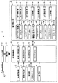
図1は、本発明に係る画像処理装置の一実施形態に係る複合機1の外観図である。図2は、複合機1の電気的構成を示すブロック図である。図1及び図2に示すように、複合機1は、スイッチ部2、電源部3、画像読取部5(画像処理部)と、画像形成部6(画像処理部)と、給紙部7(画像処理部)と、通信部8(画像処理部)と、操作表示部4と、本体制御部10と、を備えている。
FIG. 1 is an external view of a
スイッチ部2は、図1に示すように、例えば複合機1の側面に設けられている。スイッチ部2は、ユーザーの操作によって、オン状態(閉状態)又はオフ状態(開状態)に切り替えられるスイッチである。スイッチ部2は、電源ケーブルLの一端に接続されている。電源ケーブルLの他端は、外部の交流電源ACに接続されている。
As shown in FIG. 1, the
スイッチ部2がユーザーの操作によってオン状態に切り替えられると、交流電源ACから供給される交流電圧(外部電圧)が、電源ケーブルLを介して電源部3へ供給される。一方、スイッチ部2がユーザーの操作によってオフ状態に切り替えられると、交流電源ACから電源部3への交流電圧の供給が遮断される。
When the
電源部3は、複合機1の内部に設けられている。電源部3は、交流電源ACから供給された交流電圧を用いて電源電圧Vを生成し、生成した電源電圧Vを、画像読取部5、画像形成部6、給紙部7、通信部8、操作表示部4、及び本体制御部10へ供給する。
The
具体的には、電源部3は、不図示のACDCコンバーターを備えている。電源部3は、スイッチ部2を介して交流電源ACから供給された交流電圧を、当該ACDCコンバーターを用いて所定レベルの直流電圧に変換する。これにより、電源部3は、当該直流電圧を電源電圧Vとして生成する。
Specifically, the
画像読取部5は、図1に示すように、複合機1の上部に設けられている。画像読取部5は、CCD(Charge Coupled Device)ラインセンサーや露光ランプ等を有する不図示の光学系ユニットを備えている。
As shown in FIG. 1, the
画像読取部5は、本体制御部10による制御の下、電源部3からの電源電圧Vの供給が開始されたときに画像読取部5の初期処理(第二初期処理)を実行する。画像読取部5の初期処理には、例えば、光学系ユニットの画像の読取精度を高めるためのキャリブレーション処理等が含まれる。
The
画像読取部5は、上記初期処理の終了後、本体制御部10による制御の下、電源電圧Vを用いて画像読取処理(画像処理)を実行する。画像読取処理とは、光学系ユニットに原稿の画像を読み取らせることにより、原稿の画像を表す画像データを生成し、当該画像データを本体制御部10へ出力する処理である。
The
画像形成部6は、複合機1の内部に設けられている。画像形成部6は、感光体ドラム、帯電部、露光部、現像部、転写部、定着部、排出部等を備えた周知の構成を有する。
The
画像形成部6は、本体制御部10による制御の下、電源部3からの電源電圧Vの供給が開始されたときに画像形成部6の初期処理(第二初期処理)を実行する。画像形成部6の初期処理には、例えば、定着部の温度を所定温度まで加熱させるウォームアップ処理等が含まれる。
The
画像形成部6は、上記初期処理の終了後、本体制御部10による制御の下、電源電圧Vを用いて画像形成処理(画像処理)を実行する。画像形成処理とは、本体制御部10に入力された画像データが表す画像を用紙に形成する処理である。
The
給紙部7は、図1に示すように、複合機1の下部に設けられた複数の給紙カセット71を備えている。各給紙カセット71には、上記画像形成処理に用いる用紙が収容されている。また、各給紙カセット71には、用紙を繰り出すための不図示の給紙ローラーや、当該各給紙カセット71に収容されている用紙の枚数を検出する用紙センサー72が設けられている。
As shown in FIG. 1, the
給紙部7は、本体制御部10による制御の下、電源部3からの電源電圧Vの供給が開始されたときに給紙部7の初期処理(第二初期処理)を実行する。給紙部7の初期処理には、例えば、用紙センサー72に検出させた用紙の枚数が0でないか否かを判断する、つまり、給紙カセット71に用紙が収容されているか否かを判断する用紙チェック処理等が含まれる。
The
給紙部7は、上記初期処理の終了後、本体制御部10による制御の下、電源電圧Vを用いて用紙給紙処理(画像処理)を実行する。用紙給紙処理とは、上記画像形成処理において画像を形成するための用紙を不図示の給紙ローラーによって給紙する処理である。
After the completion of the initial processing, the
通信部8は、複合機1の内部に設けられている。通信部8は、LAN(Local Area Network)等の不図示のネットワークに接続され、当該ネットワークに接続された外部装置(例:パーソナルコンピュータ等)との間で各種データの送受信を行う通信インターフェイス回路である。
The
通信部8は、本体制御部10による制御の下、電源部3からの電源電圧Vの供給が開始されたときに通信部8の初期処理(第二初期処理)を実行する。通信部8の初期処理には、例えば、データを送受信する通信ポートが正常に動作するか否かをチェックするポート初期化処理等が含まれる。
The
通信部8は、上記初期処理の終了後、本体制御部10による制御の下、電源電圧Vを用いて画像受信処理(画像処理)及び画像送信処理(画像処理)を実行する。画像受信処理とは、上記画像形成処理に用いる画像データを外部装置から受信し、受信した画像データを本体制御部10へ出力する処理である。画像送信処理とは、上記画像読取処理において出力された画像データを指定された外部装置へ送信する処理である。
The
操作表示部4は、図1に示すように、複合機1の正面部に設けられている。操作表示部4は、電源電圧Vを用いて動作する。操作表示部4は、ユーザーによる種々の操作指示が入力可能に構成されている。
As shown in FIG. 1, the
具体的には、操作表示部4は、タッチパネル装置41と、インジケーター42と、入力キー43と、機能切替スイッチ44と、スタートキー45(入力部)と、ストップキー46と、リセットキー47と、スピーカー48と、操作制御部49と、を備えている。
Specifically, the
タッチパネル装置41は、液晶ディスプレイ等の表示部411を備えている。また、タッチパネル装置41は、静電容量方式のタッチパネル機能を有している。タッチパネル機能とは、ユーザーが指やペン等の指示体を表示部411に近づけたときに生じる静電容量の変化に基づいて、ユーザーが指示体を用いてタッチ操作した、表示部411に表示されているソフトキー等の画面部品を検出する機能である。尚、タッチパネル機能は、静電容量方式に限らず、例えば、超音波方式や光学方式であってもよい。
The
インジケーター42は、LED等の発光素子からなる。インジケーター42は、点滅或いは点灯/消灯することによって複合機1の状態を示す。入力キー43は、数字や記号を入力したり、入力済みの文字列を消去又は確定するために設けられている。
機能切替スイッチ44は、実行対象の機能を切り替えるスイッチである。複合機1において実行可能な機能には、例えば、コピー機能、送信機能等が含まれる。コピー機能とは、画像読取部5に画像読取処理を実行させた後、給紙部7に用紙給紙処理を実行させながら、当該画像読取処理で出力された画像データと当該用紙給紙処理で給紙された用紙とを用いて、画像形成部6に画像形成処理を実行させる機能である。送信機能とは、画像読取部5に画像読取処理を実行させた後、当該画像読取処理で出力された画像データを用いて、通信部8に画像送信処理を実行させる機能である。例えば、機能切替スイッチ44には、実行対象の機能をコピー機能に切り替えるスイッチ、及び、実行対象の機能を送信機能に切り替えるスイッチ等が含まれる。
The
機能切替スイッチ44が押下されることにより、実行対象の機能が切り替えられた場合、後述する操作制御部49による制御の下、当該切り替え後の実行対象の機能に対応する操作画面が表示部411に表示される。機能に対応する操作画面とは、当該機能の実行時に用いる実行条件が入力可能な操作画面を示す。実行条件については後述する。
When the
スタートキー45は、表示部411に表示されている操作画面に対応する機能を実行させる実行指示を入力するために設けられている。例えば、コピー機能に対応する操作画面が表示部411に表示されているとする。この場合、スタートキー45が押下されると、コピー機能を実行させる実行指示が入力される。
The
また、スタートキー45には、後述する点灯制御部95による制御の下、点灯又は消灯されるLED451(発光素子)が設けられている。
Further, the
ストップキー46は、各機能の実行を停止するために設けられている。リセットキー47は、各機能の実行時に用いる実行条件を所定の初期値に戻すために設けられている。
The
スピーカー48は、後述する警告部96により入力された音声データに対応する音声を出力する。尚、スピーカー48は、所謂ビープ音のみを出力可能であってもよい。この場合、スピーカー48は、後述する警告部96による指示の下、当該ビープ音を出力する。
The
操作制御部49は、操作表示部4の各部の動作を制御する。具体的には、操作制御部49は、所定の演算処理を実行する不図示のCPU(Central Processing Unit)と、所定の制御プログラムが記憶されたEEPROM等の不図示の不揮発性メモリーと、データを一時的に記憶するための不図示のRAM(Random Access Memory)と、これらの周辺回路等を備えている。
The
操作制御部49は、不揮発性メモリー等に記憶された制御プログラムをCPUに実行させることにより、例えば、表示制御部91、条件設定部92、指示制限部94、点灯制御部95、及び警告部96として動作する。また、操作制御部49は、RAMの記憶領域の一部を記憶部93として用いる。
The
表示制御部91は、本体制御部10による制御の下、電源部3からの電源電圧Vの供給が開始されたときに、操作表示部4の初期処理(第一初期処理)を実行する。操作表示部4の初期処理には、例えば、本体制御部10が当該初期処理を実行させるために操作制御部49へ出力した初期データをRAMに記憶するデータロード処理等が含まれる。初期データには、操作画面を表す画面データ、警告音を表す音声データ、初期機能を示す初期機能データ、各機能の実行時に用いる実行条件の初期値等が含まれている。
The
また、表示制御部91は、操作表示部4の初期処理の終了後、上記初期機能データが示す初期機能に対応する操作画面を表す画面データをRAMから取得する。そして、表示制御部91は、当該取得した画面データが表す操作画面を表示部411に表示する。
Further, the
条件設定部92は、画像読取部5、画像形成部6、給紙部7及び通信部8のうち何れかの動作部が初期処理を実行中に、操作画面を用いて実行条件が入力された場合、当該実行条件を記憶部93に記憶する。以下、画像読取部5、画像形成部6、給紙部7及び通信部8を総称して、画像処理部と記載する。
The
そして、条件設定部92は、全ての画像処理部が初期処理を終了した後、記憶部93に記憶されている実行条件を後述する条件受付部12へ出力する。
Then, after all the image processing units have completed the initial processing, the
一方、条件設定部92は、全ての画像処理部が初期処理を終了した後、操作画面を用いて実行条件が入力された場合は、当該実行条件を記憶部93には記憶せずに、後述する条件受付部12へ出力する。
On the other hand, the
図3は、操作画面W1の一例を示す図である。例えば、上記初期機能データが示す初期機能が、コピー機能であるとする。この場合、図3に示すように、表示制御部91は、操作表示部4の初期処理を終了後、コピー機能に対応する操作画面W1を表示部411に表示する。
FIG. 3 is a diagram illustrating an example of the operation screen W1. For example, it is assumed that the initial function indicated by the initial function data is a copy function. In this case, as illustrated in FIG. 3, the
操作画面W1には、コピー機能の実行時に行われる画像読取処理、用紙給紙処理及び画像形成処理で用いる7つの実行条件をそれぞれ入力するためのソフトキーが設けられている。 The operation screen W1 is provided with soft keys for inputting seven execution conditions used in the image reading process, the paper feeding process, and the image forming process performed when the copy function is executed.
具体的には、操作画面W1には、上記7つのソフトキーとして、実行条件「部数」を入力するための部数キーSK1、実行条件「用紙」を入力するための用紙キーSK2、実行条件「縮小/拡大」を入力するための縮小/拡大キーSK3、実行条件「両面/分割」を入力するための両面/分割キーSK4、実行条件「濃度」を入力するための濃度キーSK5、実行条件「ページ集約」を入力するためのページ集約キーSK6、実行条件「排出先」を入力するための排出先キーSK7が設けられている。 Specifically, on the operation screen W1, as the above seven soft keys, a copy key SK1 for inputting the execution condition “number of copies”, a paper key SK2 for inputting the execution condition “paper”, and an execution condition “reduction” Reduction / enlargement key SK3 for inputting "/ enlarge", duplex / divide key SK4 for inputting execution condition "double-sided / divided", density key SK5 for inputting execution condition "density", execution condition "page" A page aggregation key SK6 for inputting “consolidation” and a discharge destination key SK7 for inputting an execution condition “discharge destination” are provided.
操作画面W1の上部には、部数キーSK1を用いて入力された実行条件「部数」を表示するための表示欄K1が設けられている。また、6つのソフトキーSK2〜SK7のそれぞれの上部には、6つのソフトキーSK2〜SK7をそれぞれ用いて入力された実行条件「用紙」、「縮小/拡大」、「両面/分割」、「濃度」、「ページ集約」、「排出先」を表示するための表示欄K2〜K7が設けられている。 In the upper part of the operation screen W1, a display field K1 for displaying the execution condition “number of copies” input using the number of copies key SK1 is provided. In addition, the execution conditions “paper”, “reduction / enlargement”, “double-side / division”, “density” input using the six soft keys SK2 to SK7 are respectively displayed above the six soft keys SK2 to SK7. ”,“ Page aggregation ”, and display fields K2 to K7 for displaying“ discharge destination ”.
上記7つのソフトキーSK1〜SK7を代表して用紙キーSK2について説明する。用紙キーSK2は、用紙給紙処理によって給紙させる用紙、つまり、画像形成処理において画像を形成するための用紙を、実行条件「用紙」として入力するためのソフトキーである。 The paper key SK2 will be described as a representative of the seven soft keys SK1 to SK7. The paper key SK2 is a soft key for inputting, as an execution condition “paper”, a paper to be fed by the paper feeding process, that is, a paper for forming an image in the image forming process.
タッチパネル装置41によって用紙キーSK2のタッチ操作が検出されると、表示制御部91は、実行条件「用紙」として入力可能な予め定められた複数種類の用紙をそれぞれ示す複数のソフトキーを、用紙キーSK2に重ねて表示する。
When the touch operation of the paper key SK2 is detected by the
例えば、複数種類の用紙には、「A4縦」、「A4横」、「B4縦」、「B4横」、「A5縦」、「B5縦」等、各給紙カセット71(図1)に収容可能な複数種類の用紙が含まれる。用紙キーSK2のタッチ操作が検出されると、表示制御部91は、「A4縦」「A4横」「B4縦」「B4横」「A5縦」「B5縦」等をそれぞれ示す複数のソフトキーを、用紙キーSK2に重ねて表示する。
For example, for a plurality of types of paper, “A4 portrait”, “A4 landscape”, “B4 portrait”, “B4 landscape”, “A5 portrait”, “B5 portrait”, etc. Multiple types of paper that can be stored are included. When the touch operation of the paper key SK2 is detected, the
そして、当該複数のソフトキーのうちの何れかのタッチ操作が検出されると、条件設定部92は、当該タッチ操作されたソフトキーが示す用紙が、実行条件「用紙」として入力されたと判断する。また、表示制御部91は、当該タッチ操作されたソフトキーが示す用紙を表示欄K2に表示する。このようにして、表示制御部91は、用紙キーSK2を用いて入力された実行条件「用紙」を、表示欄K2に表示する。
When any touch operation of the plurality of soft keys is detected, the
例えば、図3は、用紙キーSK2がタッチ操作された後、「A4縦」を示すソフトキーがタッチ操作された例を示している。つまり、図3は、用紙キーSK2を用いて、実行条件「用紙」として「A4縦」が入力された例を示している。尚、実行条件の入力方法を、これに限定する趣旨ではない。 For example, FIG. 3 shows an example in which the soft key indicating “A4 portrait” is touched after the paper key SK2 is touched. That is, FIG. 3 shows an example in which “A4 portrait” is input as the execution condition “paper” using the paper key SK2. Note that the execution condition input method is not limited to this.
条件設定部92は、上記7つのソフトキーSK1〜SK7を用いて実行条件が入力された場合に、何れかの画像処理部が初期処理中のときは、当該実行条件を記憶部93に記憶する。一方、条件設定部92は、上記7つのソフトキーSK1〜SK7を用いて実行条件が入力された場合に、全ての画像処理部が初期処理を終了しているときは、当該実行条件を記憶部93には記憶せずに、後述する条件受付部12へ出力する。
The
指示制限部94は、スタートキー45を用いて実行指示が入力された場合に、何れかの画像処理部が初期処理を終了していないときは、当該実行指示を後述する指示受付部13へ出力しない。一方、指示制限部94は、全ての画像処理部が初期処理を終了しているときは、当該実行指示を後述する指示受付部13へ出力する。
When an execution instruction is input using the
点灯制御部95は、何れかの画像処理部が初期処理を終了していない場合にLED451を消灯させ、全ての画像処理部が初期処理を終了している場合にLED451を点灯させる。
The
警告部96は、何れかの画像処理部が初期処理を終了していない場合に、スタートキー45を用いて実行指示が入力されたとき、操作表示部4の初期処理時にRAMに記憶された音声データが示す警告音をスピーカー48に出力させる。尚、上述のように、スピーカー48がビープ音のみを出力可能に構成されている場合、警告部96は当該ビープ音を上記警告音としてスピーカー48に出力させる。
The
本体制御部10は、複合機1の内部に設けられている。本体制御部10は、複合機1の各部の動作を制御する。具体的には、本体制御部10は、所定の演算処理を実行する不図示のCPU(Central Processing Unit)と、所定の制御プログラムが記憶されたEEPROM等の不図示の不揮発性メモリーと、データを一時的に記憶するための不図示のRAM(Random Access Memory)と、これらの周辺回路等を備えている。
The main
本体制御部10は、不揮発性メモリー等に記憶された制御プログラムをCPUに実行させることにより、例えば、初期化制御部11、条件受付部12、指示受付部13、及び実行制御部14として動作する。
The main
初期化制御部11は、ユーザーがスイッチ部2をオン状態に切り替える操作を行うことによって、電源部3により電源電圧Vの供給が開始されたときに、表示制御部91に操作表示部4の初期処理(第一初期処理)を開始させる。また、初期化制御部11は、操作表示部4の初期処理を開始させた後、各画像処理部に初期処理(第二初期処理)を開始させる。
The
また、初期化制御部11は、全ての画像処理部が初期処理を終了したときに、全ての画像処理部が初期処理を終了したことを示す終了通知データを操作制御部49へ出力する。これにより、初期化制御部11は、全ての画像処理部が初期処理を終了したことを操作制御部49へ通知する。
The
条件受付部12は、全ての画像処理部が初期処理を終了した後、実行条件の入力を受け付ける。具体的には、条件受付部12は、全ての画像処理部が初期処理を終了した後、条件設定部92によって出力された実行条件が入力されると、当該入力された実行条件を受け付ける。
The
指示受付部13は、全ての画像処理部が初期処理を終了した後、実行指示の入力を受け付ける。具体的には、指示受付部13は、全ての画像処理部が初期処理を終了した後、指示制限部94によって出力された実行指示が入力されると、当該入力された実行指示を受け付ける。
The
実行制御部14は、指示受付部13により実行指示が受け付けられた場合、条件受付部12により受け付けられた実行条件を用いて、当該実行指示が示す機能を実行させる。
When the execution instruction is received by the
例えば、条件受付部12によりコピー機能の実行時に用いる実行条件が受け付けられ、指示受付部13によりコピー機能の実行指示が受け付けられたとする。この場合、実行制御部14は、当該コピー機能の実行時に用いる実行条件を用いてコピー機能を実行させる。つまり、実行制御部14は、当該実行条件を用いて、画像読取部5に画像読取処理を実行させた後、給紙部7に用紙給紙処理を実行させながら、当該画像読取処理で出力された画像データと当該用紙給紙処理で給紙された用紙とを用いて、画像形成部6に画像形成処理を実行させる。
For example, it is assumed that the
また、実行制御部14は、条件受付部12によって受け付けられた実行条件に不正な実行条件が含まれている場合、指示受付部13によって受け付けられた実行指示が示す機能を実行させず、不正な実行条件が含まれている旨のメッセージを、表示制御部91によって表示部411に表示させる。不正な実行条件とは、機能の実行時に用いることができない実行条件を示す。
In addition, when the execution condition received by the
例えば、全ての画像処理部が初期処理を終了した後、条件受付部12によって受け付けられた実行条件「用紙」が「A4縦」を示していたとする。また、給紙部7は、初期処理時に、「A4縦」の用紙を収容するための給紙カセット71に用紙が収容されていないと判断していたとする。
For example, assume that the execution condition “paper” received by the
この場合、実行条件「用紙」が示す「A4縦」の用紙が存在しないので、当該実行条件「用紙」を用いてコピー機能を実行することができない。つまり、当該実行条件「用紙」は、不正な実行条件である。この場合、実行制御部14は、コピー機能を実行させず、表示制御部91に、例えばメッセージ「「用紙」の入力が不正です。」を表示部411に表示させる。
In this case, since there is no “A4 portrait” paper indicated by the execution condition “paper”, the copy function cannot be executed using the execution condition “paper”. That is, the execution condition “paper” is an illegal execution condition. In this case, the
以下、本体制御部10及び操作表示部4の動作について説明する。図4は、本体制御部10の動作を示すフローチャートである。
Hereinafter, operations of the main
先ず、本体制御部10の動作について説明する。図4に示すように、ユーザーの操作によってスイッチ部2がオン状態に切り替えられると(S1)、交流電源ACから供給される交流電圧が、電源ケーブルLを介して電源部3へ供給される。これにより、電源部3は、交流電圧を用いて電源電圧Vを生成し、電源電圧Vの供給を開始する(S2)。
First, the operation of the main
このとき、初期化制御部11は、表示制御部91に操作表示部4の初期処理を開始させる(S3)。具体的には、初期化制御部11は、ステップS3において、複合機1において実行可能な各機能に対応する操作画面を表す画面データ、警告音を表す音声データ、初期機能を示す初期機能データ、各機能の実行時に用いる実行条件の初期値等を含む初期データをROM等から取得する。そして、初期化制御部11は、当該取得した初期データを操作制御部49へ出力する。このときの操作表示部4の動作については後述する。
At this time, the
次に、初期化制御部11は、各画像処理部(画像読取部5、画像形成部6、給紙部7、通信部8)にそれぞれ初期処理を開始させる(S4)。
Next, the
全ての画像処理部が初期処理を終了すると(S5;YES)、初期化制御部11は、全ての画像処理部が初期処理を終了したことを示す終了通知データを操作制御部49へ出力する。これにより、初期化制御部11は、全ての画像処理部が初期処理を終了したことを操作制御部49へ通知する(S6)。
When all the image processing units finish initial processing (S5; YES), the
ステップS6以降、条件設定部92によって出力された実行条件が条件受付部12に入力されると(S7;YES)、条件受付部12は、当該入力された実行条件を受け付ける(S8)。
After step S6, when the execution condition output by the
条件受付部12によって実行条件が受け付けられた後、指示制限部94によって出力された実行指示が指示受付部13に入力されない間は(S9;NO)、ステップS7以降の処理が繰り返される。そして、条件受付部12によって実行条件が受け付けられた後、指示制限部94によって出力された実行指示が指示受付部13に入力されると(S9;YES)、指示受付部13は、当該入力された実行指示を受け付ける(S10)。
After the execution condition is received by the
指示受付部13により実行指示が受け付けられると、実行制御部14は、ステップS8で受け付けられた実行条件に不正な実行条件が含まれているか否かを判定する(S11)。
When the execution instruction is received by the
実行制御部14は、ステップS11において、不正な実行条件が含まれていないと判定した場合(S11;NO)、ステップS8で受け付けられた実行条件を用いて、ステップS10で受け付けられた実行指示が示す機能を実行させる(S12)。
If the
一方、実行制御部14は、ステップS11において、不正な実行条件が含まれていると判定した場合(S11;YES)、ステップS10で受け付けられた実行指示が示す機能を実行させず、不正な実行条件が含まれている旨のメッセージを表示制御部91によって表示部411に表示させる(S13)。
On the other hand, if the
ステップS12及びステップS13以降は、ステップS7以降の処理が繰り返される。 After step S12 and step S13, the processing after step S7 is repeated.
以下、操作表示部4の動作について説明する。図5は、操作表示部4の動作を示すフローチャートである。図5に示すように、ステップS1(図4)及びステップS2(図4)により、操作表示部4への電源電圧Vの供給が開始された後、表示制御部91は、ステップS3における初期化制御部11による指示の下、操作表示部4の初期処理を実行する(S21)。
Hereinafter, the operation of the
尚、表示制御部91は、ステップS21において、初期化制御部11がステップS3(図4)において操作制御部49へ出力した初期データを取得し、当該取得した初期データをRAMに記憶する。上述のように、初期データには、各操作画面を表す画面データ、警告音を表す音声データ、初期機能を示す初期機能データ、各機能の実行時に用いる実行条件の初期値等が含まれている。
In step S21, the
表示制御部91は、操作表示部4の初期処理の終了後、初期機能データが示す初期機能に対応する操作画面(例えば、操作画面W1(図3))を表す画面データをRAMから取得する。そして、表示制御部91は、当該取得した画面データが表す操作画面を表示部411に表示する(S22)。
After the initial processing of the
尚、表示制御部91は、ステップS22において、初期機能の実行条件の初期値をRAMから取得し、当該取得した初期値を操作画面内に設けられた実行条件の表示欄(例えば、操作画面W1の場合、表示欄K1〜K7)に表示する。
In step S22, the
そして、何れかの画像処理部が初期処理を終了していず、ステップS6(図4)が行われていなかったとする。つまり、終了通知データが操作制御部49に入力されていず、全ての画像処理部が初期処理を終了したことが操作制御部49に通知されていなかったとする(S23;NO)。
Then, it is assumed that any of the image processing units has not finished the initial process, and step S6 (FIG. 4) has not been performed. That is, it is assumed that the end notification data has not been input to the
この場合、点灯制御部95は、LED451を消灯させる(S24)。そして、操作画面を用いて実行条件が入力された場合(S25;YES)、条件設定部92は、当該入力された実行条件を記憶部93に記憶する(S26)。
In this case, the
尚、ステップS22又は後述のステップS37において実行条件の初期値が操作画面に表示されたときに、全ての画像処理部が初期処理を終了したことが操作制御部49に通知されていなかったとする(S23;NO)。このときも、条件設定部92は、上記の初期値の表示によって実行条件が入力されたと判断し(S25;YES)、ステップS26を実行する。当該ステップS26において、条件設定部92は、ステップS22又は後述のステップS37において操作画面に表示された実行条件を、当該操作画面を用いて入力された実行条件として記憶部93に記憶する。
Note that when the initial value of the execution condition is displayed on the operation screen in step S22 or step S37 described later, it is assumed that the
そして、ユーザーがスタートキー45を押下したことにより、操作画面に対応する機能を実行させる実行指示が入力された場合(S27;YES)、指示制限部94は当該実行指示を指示受付部13へ出力しない。この場合、警告部96は、RAMに記憶されている音声データが示す警告音をスピーカー48に出力させる(S28)。
When an execution instruction for executing a function corresponding to the operation screen is input by the user pressing the start key 45 (S27; YES), the
一方、全ての画像処理部が初期処理を終了しており、ステップS6(図4)が行われていたとする。つまり、終了通知データが操作制御部49に入力されており、全ての画像処理部が初期処理を終了したことが操作制御部49に通知されていたとする(S23;YES)。
On the other hand, it is assumed that all the image processing units have completed the initial processing, and step S6 (FIG. 4) has been performed. That is, it is assumed that the end notification data is input to the
この場合、点灯制御部95は、LED451を点灯させる(S29)。そして、記憶部93に実行条件が記憶されている場合(S30;YES)、条件設定部92は、記憶部93から当該実行条件を取得し、当該取得した実行条件を条件受付部12へ出力する(S31)。尚、条件設定部92は、ステップS31において実行条件を出力した後は、記憶部93に記憶されている当該実行条件を削除する。
In this case, the
その後、操作画面を用いて実行条件が入力された場合(S32;YES)、条件設定部92は、当該入力された実行条件を記憶部93に記憶せずに、当該入力された実行条件を条件受付部12へ出力する(S33)。
Thereafter, when an execution condition is input using the operation screen (S32; YES), the
尚、ステップS22又は後述のステップS37において実行条件の初期値が操作画面に表示されたときに、全ての画像処理部が初期処理を終了したことが操作制御部49に通知されていたとする(S23;YES)。このときも、条件設定部92は、上記の初期値の表示によって実行条件が入力されたと判断し(S32;YES)、ステップS33を実行する。当該ステップS33において、条件設定部92は、ステップS22又は後述のステップS37において操作画面に表示された実行条件を、当該操作画面を用いて入力された実行条件として条件受付部12へ出力する。
When the initial value of the execution condition is displayed on the operation screen in step S22 or step S37, which will be described later, it is assumed that the
そして、ユーザーがスタートキー45を押下したことにより、操作画面に対応する機能を実行させる実行指示が入力された場合(S34;YES)、指示制限部94は、当該実行指示を指示受付部13へ出力する(S35)。
When the execution instruction for executing the function corresponding to the operation screen is input by the user pressing the start key 45 (S34; YES), the
以降、ユーザーによる機能切替スイッチ44の押下によって実行対象の機能が切り替えられるまでの間は(S36;NO)、ステップS23以降の処理が繰り返される。機能切替スイッチ44の押下によって実行対象の機能が切り替えられた場合は(S36;YES)、表示制御部91は、当該切り替え後の実行対象の機能に対応する操作画面を表す画面データをRAMから取得する。そして、表示制御部91は、表示部411に表示中の操作画面に代えて、当該取得した画面データが表す操作画面を表示部411に表示する(S37)。そして、ステップS23以降の処理が繰り返される。
Thereafter, the processing after step S23 is repeated until the function to be executed is switched by pressing the
このように、上記実施形態の構成によれば、何れかの画像処理部が初期処理を実行しているときに(S23;NO)、操作画面を用いて実行条件が入力された場合(S25;YES)、当該実行条件が記憶部93に記憶される(S26)。そして、全ての画像処理部が初期処理を終了した後に(S23;YES)、記憶部93に記憶されている実行条件が条件受付部12へ出力される(S33)。
As described above, according to the configuration of the above-described embodiment, when any of the image processing units is executing the initial process (S23; NO), when an execution condition is input using the operation screen (S25; YES), the execution condition is stored in the storage unit 93 (S26). Then, after all the image processing units have completed the initial process (S23; YES), the execution conditions stored in the
このため、ユーザーは、スイッチ部2を用いて交流電圧の供給を開始する操作を行ってから、全ての画像処理部が初期処理を終了するまでの期間内に、機能の実行時に用いる実行条件を入力することができる。また、当該期間の経過後、当該期間内に入力した実行条件を条件受付部12に受け付けさせることができる。これにより、交流電圧が供給されていない状態の複合機1に出向いたユーザーは、上記期間中に実行条件を入力しておき、上記期間の経過後迅速に、上記期間中に入力した実行条件を用いて機能を実行させることができる。
For this reason, the user sets the execution condition used when executing the function within the period from when the operation of starting the supply of the AC voltage using the
また、上記実施形態の構成によれば、スタートキー45を用いて実行指示が入力された場合に、全ての画像処理部が初期処理を終了していないときは(S23;NO、S27;YES)、当該実行指示が指示受付部13へ出力されず、全ての画像処理部が初期処理を終了しているときは(S23;YES、S34;YES)、当該実行指示が指示受付部13へ出力される(S35)。
Further, according to the configuration of the above embodiment, when an execution instruction is input using the
このため、全ての画像処理部が初期処理を終了しているときに限り、指示受付部13に実行指示を受け付けさせることができる。これにより、何れかの画像処理部が初期処理を終了していないうちに機能が実行されることによって、当該機能が正常に実行されない虞を低減することができる。
For this reason, the
また、上記実施形態の構成によれば、何れかの画像処理部が初期処理を終了していない場合(S23;NO)、LED451は消灯し(S24)、全ての画像処理部が初期処理を終了している場合(S23;YES)、LED451は点灯する(S29)。このため、ユーザーは、LED451が点灯しているか否かに応じて、複合機1が機能を実行させることのできる状態であるか否かを容易に判別することができる。
Further, according to the configuration of the above embodiment, if any of the image processing units has not finished the initial processing (S23; NO), the
また、上記実施形態の構成によれば、何れかの画像処理部が初期処理を終了していない場合に(S23;NO)、スタートキー45を用いて実行指示が入力されたとき(S27;YES)、警告音が出力される(S28)。このため、ユーザーは、当該警告音を聞くことによって、複合機1が機能を実行させることのできない状態であることに容易に気付くことができる。
Further, according to the configuration of the above embodiment, when any image processing unit has not finished the initial processing (S23; NO), when an execution instruction is input using the start key 45 (S27; YES) ), A warning sound is output (S28). For this reason, the user can easily recognize that the
また、上記実施形態の構成によれば、条件受付部12によって受け付けられた実行条件に不正な実行条件が含まれている場合(S11;YES)、指示受付部13により受け付けられた実行指示が示す機能は実行されず、不正な実行条件が含まれていることを示すメッセージが表示部411に表示される(S13)。このため、ユーザーは、当該メッセージを視認後、迅速に当該不正な実行条件を入力し直すことができる。
Further, according to the configuration of the above-described embodiment, when the execution condition received by the
尚、上記実施形態は、本発明に係る実施形態の例示に過ぎず、本発明を上記実施形態に限定する趣旨ではない。例えば、以下に示す、変形実施形態であってもよい。 In addition, the said embodiment is only the illustration of embodiment which concerns on this invention, and is not the meaning which limits this invention to the said embodiment. For example, the following modified embodiment may be used.
(1)実行制御部14が、ステップS11(図4)において、ステップS8(図4)で受け付けられた実行条件に不正な実行条件が含まれていると判定した場合に、ステップS13(図4)を行わないようにしてもよい。そして、この場合、実行制御部14が、例えば、当該不正な実行条件をROM等に記憶されている当該実行条件の初期値に変更するようにしてもよい。更に、実行制御部14が、当該変更後の実行条件を用いてステップS10(図4)で受け付けられた実行指示が示す機能を実行させるようにしてもよい。
(1) When the
(2)操作制御部49が警告部96として動作しないようにして、ステップS28(図5)を省略してもよい。
(2) Step S28 (FIG. 5) may be omitted by preventing the
(3)スタートキー45にLED451を設けないようにしてもよい。これに合わせて、操作制御部49が点灯制御部95として動作しないようにして、ステップS24(図5)及びステップS29(図5)を省略してもよい。
(3) The start key 45 may not be provided with the
(4)操作制御部49が指示制限部94として動作しないようにしてもよい。これに合わせて、操作制御部49は、スタートキー45を用いて実行指示が入力された場合(S27;YES、S34;YES)、全ての画像処理部が初期処理を終了しているか否かによらず、当該実行指示を指示受付部13へ出力するようにしてもよい。ただし、指示受付部13は、上述のように、全ての画像処理部が初期処理を終了してないときには、入力された実行指示を受け付けない。
(4) The
1 複合機(画像処理装置)
2 スイッチ部
3 電源部
4 操作表示部
5 画像読取部(画像処理部)
6 画像形成部(画像処理部)
7 給紙部(画像処理部)
8 通信部(画像処理部)
11 初期化制御部
12 条件受付部
13 指示受付部
14 実行制御部
45 スタートキー(入力部)
49 操作制御部
91 表示制御部
92 条件設定部
93 記憶部
94 指示制限部
95 点灯制御部
96 警告部
411 表示部
451 LED(発光素子)
V 電源電圧
W1 操作画面
1 MFP (image processing device)
2
6 Image forming unit (image processing unit)
7 Paper feed unit (image processing unit)
8 Communication unit (image processing unit)
DESCRIPTION OF
49
V Power supply voltage W1 Operation screen
Claims (5)
前記外部電圧を用いて電源電圧を生成し、生成した前記電源電圧を供給する電源部と、
前記電源電圧を用いて動作する操作表示部と、
前記電源電圧を用いて所定の画像処理を実行する画像処理部と、
ユーザーが前記スイッチ部を用いて前記操作を行うことによって前記電源部により前記電源電圧の供給が開始されたときに、前記画像処理に用いる実行条件が入力可能な操作画面を表す画面データを前記操作表示部に出力して、前記操作表示部に所定の第一初期処理を開始させ、前記第一初期処理の開始後、前記画像処理部に所定の第二初期処理を開始させる初期化制御部と、
前記第二初期処理の終了後、前記実行条件の入力を受け付ける条件受付部と、
を備え、
前記操作表示部は、
表示部と、
記憶部と、
前記第一初期処理において、前記初期化制御部から取得した前記画面データを前記記憶部に記憶し、前記第一初期処理の終了後、前記記憶部から前記画面データを取得し、当該取得した前記画面データが表す前記操作画面を前記表示部に表示する表示制御部と、
前記第二初期処理中に前記操作画面を用いて前記実行条件が入力された場合、当該実行条件を前記記憶部に記憶し、前記第二初期処理の終了後に、前記記憶部に前記実行条件が記憶されている場合には、前記記憶部に記憶されている前記実行条件を前記条件受付部へ出力した後、前記記憶部に記憶されている前記実行条件を削除し、当該削除後、前記操作画面を用いて前記実行条件が入力された場合、当該入力された前記実行条件を前記記憶部には記憶せずに、前記条件受付部へ出力する条件設定部と、
を備える画像処理装置。 A switch used by a user to start an external voltage supply;
Generating a power supply voltage using the external voltage, and supplying the generated power supply voltage; and
An operation display unit that operates using the power supply voltage;
An image processing unit that executes predetermined image processing using the power supply voltage;
When the user performs the operation using the switch unit and the supply of the power supply voltage is started by the power supply unit, screen data representing an operation screen to which an execution condition used for the image processing can be input is the operation An initialization control unit that outputs to the display unit, causes the operation display unit to start predetermined first initial processing, and causes the image processing unit to start predetermined second initial processing after the first initial processing starts; ,
After completion of the second initialization process, a condition acceptance unit that accepts an input of the pre-you line conditions,
With
The operation display unit
A display unit;
A storage unit;
In the first initial process, the screen data acquired from the initialization control unit is stored in the storage unit, and after the first initial process, the screen data is acquired from the storage unit, and the acquired a display control unit that displays the steering drawing plane indicated by the screen data on the display unit,
When the execution condition is input using the operation screen during the second initial process, the execution condition is stored in the storage unit. After the second initial process is completed, the execution condition is stored in the storage unit. If stored, the execution condition stored in the storage unit is output to the condition receiving unit, then the execution condition stored in the storage unit is deleted, and after the deletion, the operation When the execution condition is input using a screen, a condition setting unit that outputs the input execution condition to the condition reception unit without storing the input execution condition in the storage unit ;
An image processing apparatus comprising:
前記指示受付部により前記実行指示が受け付けられた場合、前記条件受付部により受け付けられた前記実行条件を用いて前記画像処理を実行させる実行制御部と、
を更に備え、
前記操作表示部は、
前記実行指示が入力可能な入力部と、
前記入力部を用いて前記実行指示が入力された場合に、前記第二初期処理が終了していないときは前記実行指示を前記指示受付部へ出力せず、前記第二初期処理が終了しているときは前記実行指示を前記指示受付部へ出力する指示制限部と、
を更に備える請求項1に記載の画像処理装置。 An instruction receiving unit that receives an input of an execution instruction for executing the image processing after the second initial processing is completed;
An execution control unit that executes the image processing using the execution condition received by the condition reception unit when the execution instruction is received by the instruction reception unit;
Further comprising
The operation display unit
An input unit capable of inputting the execution instruction;
When the execution instruction is input using the input unit, if the second initial process is not completed, the execution instruction is not output to the instruction receiving unit, and the second initial process is completed. An instruction limiting unit that outputs the execution instruction to the instruction receiving unit when
The image processing apparatus according to claim 1, further comprising:
前記操作表示部は、
前記第二初期処理が終了していない場合に前記発光素子を消灯させ、前記第二初期処理が終了している場合に前記発光素子を点灯させる点灯制御部を更に備える請求項2に記載の画像処理装置。 The input unit is provided with a light emitting element,
The operation display unit
The image according to claim 2, further comprising a lighting control unit that turns off the light emitting element when the second initial process is not completed and turns on the light emitting element when the second initial process is completed. Processing equipment.
前記第二初期処理が終了していない場合に、前記入力部を用いて前記実行指示が入力されたとき、所定の警告音を出力する警告部を更に備える請求項2又は3に記載の画像処理装置。 The operation display unit
4. The image processing according to claim 2, further comprising: a warning unit that outputs a predetermined warning sound when the execution instruction is input using the input unit when the second initial processing is not completed. 5. apparatus.
Priority Applications (2)
| Application Number | Priority Date | Filing Date | Title |
|---|---|---|---|
| JP2014241286A JP6060137B2 (en) | 2014-11-28 | 2014-11-28 | Image processing device |
| US14/948,619 US9813584B2 (en) | 2014-11-28 | 2015-11-23 | Image processing apparatus capable of performing image processing immediately after starting to be supplied with an external voltage |
Applications Claiming Priority (1)
| Application Number | Priority Date | Filing Date | Title |
|---|---|---|---|
| JP2014241286A JP6060137B2 (en) | 2014-11-28 | 2014-11-28 | Image processing device |
Publications (2)
| Publication Number | Publication Date |
|---|---|
| JP2016103754A JP2016103754A (en) | 2016-06-02 |
| JP6060137B2 true JP6060137B2 (en) | 2017-01-11 |
Family
ID=56079979
Family Applications (1)
| Application Number | Title | Priority Date | Filing Date |
|---|---|---|---|
| JP2014241286A Expired - Fee Related JP6060137B2 (en) | 2014-11-28 | 2014-11-28 | Image processing device |
Country Status (2)
| Country | Link |
|---|---|
| US (1) | US9813584B2 (en) |
| JP (1) | JP6060137B2 (en) |
Families Citing this family (1)
| Publication number | Priority date | Publication date | Assignee | Title |
|---|---|---|---|---|
| JP6583695B2 (en) * | 2017-03-17 | 2019-10-02 | 京セラドキュメントソリューションズ株式会社 | Image forming apparatus |
Family Cites Families (10)
| Publication number | Priority date | Publication date | Assignee | Title |
|---|---|---|---|---|
| JP3167983B2 (en) * | 1990-05-09 | 2001-05-21 | シャープ株式会社 | Reservable image forming method |
| JPH0588490A (en) | 1991-09-30 | 1993-04-09 | Ricoh Co Ltd | Copying machine |
| JPH08248830A (en) * | 1995-03-13 | 1996-09-27 | Ricoh Co Ltd | Image forming device |
| JPH11334179A (en) * | 1998-05-22 | 1999-12-07 | Canon Inc | Printer, printing method and storage medium |
| JP2002225394A (en) * | 2001-01-30 | 2002-08-14 | Ricoh Co Ltd | Imaging apparatus |
| JP2006224327A (en) * | 2005-02-15 | 2006-08-31 | Canon Inc | Laminator |
| JP4775332B2 (en) * | 2007-06-14 | 2011-09-21 | ブラザー工業株式会社 | Image selection apparatus and image selection method |
| JP2010274575A (en) | 2009-05-29 | 2010-12-09 | Sharp Corp | Image forming apparatus and printing system |
| JP6028468B2 (en) * | 2011-09-13 | 2016-11-16 | 株式会社リコー | Image processing system and image processing method |
| JP2013207774A (en) | 2012-03-29 | 2013-10-07 | Sharp Corp | Image forming apparatus, communication system, start-up method of image forming apparatus, program, and recording medium |
-
2014
- 2014-11-28 JP JP2014241286A patent/JP6060137B2/en not_active Expired - Fee Related
-
2015
- 2015-11-23 US US14/948,619 patent/US9813584B2/en not_active Expired - Fee Related
Also Published As
| Publication number | Publication date |
|---|---|
| US20160156808A1 (en) | 2016-06-02 |
| JP2016103754A (en) | 2016-06-02 |
| US9813584B2 (en) | 2017-11-07 |
Similar Documents
| Publication | Publication Date | Title |
|---|---|---|
| JP5923477B2 (en) | Display input device, image forming apparatus | |
| JP5693408B2 (en) | Operating device | |
| JP6005621B2 (en) | Image forming apparatus | |
| US9749488B2 (en) | Image reading apparatus that reads by intended read size and image processing apparatus | |
| JP6500863B2 (en) | Image forming device | |
| JP2007334025A (en) | Operation apparatus and image forming apparatus | |
| JP2016118959A (en) | Display input device and image forming apparatus including the same | |
| JP6060137B2 (en) | Image processing device | |
| JP5473492B2 (en) | Image forming apparatus, image forming apparatus control method, and program | |
| JP2017207794A (en) | Operation input device, image forming apparatus, and operation input method | |
| JP2008117193A (en) | Touch panel device and image processing unit having the same | |
| JP6579083B2 (en) | Image processing device | |
| WO2018047555A1 (en) | Image forming device and method of controlling image forming device | |
| EP4273689A1 (en) | Image forming apparatus and input device | |
| JP7444100B2 (en) | User interface device, image forming device, control method, and control program | |
| JP5567541B2 (en) | Image forming apparatus | |
| JP6120754B2 (en) | Display input device and image forming apparatus having the same | |
| JP6572852B2 (en) | Image forming apparatus and image forming method | |
| JP2017196868A (en) | Image processing device, method for controlling image processing device and program | |
| JP6436104B2 (en) | Display input device and image forming apparatus having the same | |
| JP2020204962A (en) | Information processing apparatus | |
| JP6035442B2 (en) | Display input device and image forming apparatus having the same | |
| JP2021197022A (en) | Information processing apparatus | |
| JP6150689B2 (en) | Image forming apparatus and setting reception method | |
| JP5843919B2 (en) | Electrical equipment and instruction reception method |
Legal Events
| Date | Code | Title | Description |
|---|---|---|---|
| A621 | Written request for application examination |
Free format text: JAPANESE INTERMEDIATE CODE: A621 Effective date: 20160520 |
|
| A871 | Explanation of circumstances concerning accelerated examination |
Free format text: JAPANESE INTERMEDIATE CODE: A871 Effective date: 20160520 |
|
| A975 | Report on accelerated examination |
Free format text: JAPANESE INTERMEDIATE CODE: A971005 Effective date: 20160804 |
|
| A977 | Report on retrieval |
Free format text: JAPANESE INTERMEDIATE CODE: A971007 Effective date: 20160808 |
|
| A131 | Notification of reasons for refusal |
Free format text: JAPANESE INTERMEDIATE CODE: A131 Effective date: 20160816 |
|
| A521 | Request for written amendment filed |
Free format text: JAPANESE INTERMEDIATE CODE: A523 Effective date: 20161017 |
|
| TRDD | Decision of grant or rejection written | ||
| A01 | Written decision to grant a patent or to grant a registration (utility model) |
Free format text: JAPANESE INTERMEDIATE CODE: A01 Effective date: 20161115 |
|
| A61 | First payment of annual fees (during grant procedure) |
Free format text: JAPANESE INTERMEDIATE CODE: A61 Effective date: 20161212 |
|
| R150 | Certificate of patent or registration of utility model |
Ref document number: 6060137 Country of ref document: JP Free format text: JAPANESE INTERMEDIATE CODE: R150 |
|
| LAPS | Cancellation because of no payment of annual fees |