JP6060080B2 - Caps and containers - Google Patents
Caps and containers Download PDFInfo
- Publication number
- JP6060080B2 JP6060080B2 JP2013533393A JP2013533393A JP6060080B2 JP 6060080 B2 JP6060080 B2 JP 6060080B2 JP 2013533393 A JP2013533393 A JP 2013533393A JP 2013533393 A JP2013533393 A JP 2013533393A JP 6060080 B2 JP6060080 B2 JP 6060080B2
- Authority
- JP
- Japan
- Prior art keywords
- skirt wall
- packing
- cleaning
- cap
- container mouth
- Prior art date
- Legal status (The legal status is an assumption and is not a legal conclusion. Google has not performed a legal analysis and makes no representation as to the accuracy of the status listed.)
- Active
Links
- 238000004140 cleaning Methods 0.000 claims description 103
- 238000012856 packing Methods 0.000 claims description 45
- 230000002093 peripheral effect Effects 0.000 claims description 31
- 239000007788 liquid Substances 0.000 claims description 30
- 238000003825 pressing Methods 0.000 claims description 4
- 238000007789 sealing Methods 0.000 claims description 4
- XLYOFNOQVPJJNP-UHFFFAOYSA-N water Substances O XLYOFNOQVPJJNP-UHFFFAOYSA-N 0.000 description 15
- 239000011295 pitch Substances 0.000 description 9
- 230000000694 effects Effects 0.000 description 5
- 239000007921 spray Substances 0.000 description 3
- 229920003002 synthetic resin Polymers 0.000 description 3
- 239000000057 synthetic resin Substances 0.000 description 3
- 238000012986 modification Methods 0.000 description 2
- 230000004048 modification Effects 0.000 description 2
- 238000005406 washing Methods 0.000 description 2
- 238000013459 approach Methods 0.000 description 1
- 230000007423 decrease Effects 0.000 description 1
- 230000006866 deterioration Effects 0.000 description 1
- 238000007599 discharging Methods 0.000 description 1
- 235000015203 fruit juice Nutrition 0.000 description 1
- 230000001771 impaired effect Effects 0.000 description 1
- 230000005764 inhibitory process Effects 0.000 description 1
- 230000001788 irregular Effects 0.000 description 1
- 239000002184 metal Substances 0.000 description 1
- 238000000034 method Methods 0.000 description 1
- 230000000149 penetrating effect Effects 0.000 description 1
- 239000006187 pill Substances 0.000 description 1
- 238000012805 post-processing Methods 0.000 description 1
- 230000037303 wrinkles Effects 0.000 description 1
Images


Classifications
-
- B—PERFORMING OPERATIONS; TRANSPORTING
- B65—CONVEYING; PACKING; STORING; HANDLING THIN OR FILAMENTARY MATERIAL
- B65D—CONTAINERS FOR STORAGE OR TRANSPORT OF ARTICLES OR MATERIALS, e.g. BAGS, BARRELS, BOTTLES, BOXES, CANS, CARTONS, CRATES, DRUMS, JARS, TANKS, HOPPERS, FORWARDING CONTAINERS; ACCESSORIES, CLOSURES, OR FITTINGS THEREFOR; PACKAGING ELEMENTS; PACKAGES
- B65D41/00—Caps, e.g. crown caps or crown seals, i.e. members having parts arranged for engagement with the external periphery of a neck or wall defining a pouring opening or discharge aperture; Protective cap-like covers for closure members, e.g. decorative covers of metal foil or paper
- B65D41/02—Caps or cap-like covers without lines of weakness, tearing strips, tags, or like opening or removal devices
- B65D41/04—Threaded or like caps or cap-like covers secured by rotation
- B65D41/0435—Threaded or like caps or cap-like covers secured by rotation with separate sealing elements
- B65D41/045—Discs
-
- B—PERFORMING OPERATIONS; TRANSPORTING
- B65—CONVEYING; PACKING; STORING; HANDLING THIN OR FILAMENTARY MATERIAL
- B65D—CONTAINERS FOR STORAGE OR TRANSPORT OF ARTICLES OR MATERIALS, e.g. BAGS, BARRELS, BOTTLES, BOXES, CANS, CARTONS, CRATES, DRUMS, JARS, TANKS, HOPPERS, FORWARDING CONTAINERS; ACCESSORIES, CLOSURES, OR FITTINGS THEREFOR; PACKAGING ELEMENTS; PACKAGES
- B65D41/00—Caps, e.g. crown caps or crown seals, i.e. members having parts arranged for engagement with the external periphery of a neck or wall defining a pouring opening or discharge aperture; Protective cap-like covers for closure members, e.g. decorative covers of metal foil or paper
- B65D41/32—Caps or cap-like covers with lines of weakness, tearing-strips, tags, or like opening or removal devices, e.g. to facilitate formation of pouring openings
- B65D41/34—Threaded or like caps or cap-like covers provided with tamper elements formed in, or attached to, the closure skirt
- B65D41/3423—Threaded or like caps or cap-like covers provided with tamper elements formed in, or attached to, the closure skirt with flexible tabs, or elements rotated from a non-engaging to an engaging position, formed on the tamper element or in the closure skirt
- B65D41/3428—Threaded or like caps or cap-like covers provided with tamper elements formed in, or attached to, the closure skirt with flexible tabs, or elements rotated from a non-engaging to an engaging position, formed on the tamper element or in the closure skirt the tamper element being integrally connected to the closure by means of bridges
-
- B—PERFORMING OPERATIONS; TRANSPORTING
- B65—CONVEYING; PACKING; STORING; HANDLING THIN OR FILAMENTARY MATERIAL
- B65D—CONTAINERS FOR STORAGE OR TRANSPORT OF ARTICLES OR MATERIALS, e.g. BAGS, BARRELS, BOTTLES, BOXES, CANS, CARTONS, CRATES, DRUMS, JARS, TANKS, HOPPERS, FORWARDING CONTAINERS; ACCESSORIES, CLOSURES, OR FITTINGS THEREFOR; PACKAGING ELEMENTS; PACKAGES
- B65D55/00—Accessories for container closures not otherwise provided for
Description
本発明は、例えば洗浄液を用いた洗浄をキャッピング後に行うのに適したキャップ及びこれを備えた容器に関する。 The present invention relates to a cap suitable for performing cleaning using a cleaning liquid after capping, for example, and a container provided with the cap.
果汁飲料等の液体を容器に充填する際、その液体が零れて容器の口部まわりに残留すると、その残留物が、黴の発生原因となったり、キャップの開栓トルクの不要な増大を招いたりし兼ねない。この問題の解決方法の一つは、キャッピング後の容器に対して、キャップのスカート壁とタンパーエビデンスバンドとを繋ぐ複数のブリッジの間からキャップと容器口部との間に洗浄液を流入させることである(特開2001−130518号公報参照)。 When filling a container with a liquid such as fruit juice, if the liquid spills and remains around the mouth of the container, the residue may cause wrinkles or cause an unnecessary increase in cap opening torque. It can be bad. One solution to this problem is to allow the cleaning liquid to flow between the cap and the container mouth through a plurality of bridges connecting the cap skirt wall and the tamper evidence band to the container after capping. Yes (see JP 2001-130518 A).
上記方法によれば、ブリッジ間からキャップ内に流入した洗浄液が残留物を除去する。しかし、斯かる洗浄の用に供するパストライザーの多くは洗浄液を容器の天面側から散水(シャワー)するだけのものであるため、実際には洗浄液がキャップの下部にあるブリッジ間からキャップ内へうまく流入しない恐れがある。 According to the above method, the cleaning liquid flowing into the cap from between the bridges removes the residue. However, since many of the past risers used for such cleaning only spray the cleaning liquid from the top side of the container (shower), the cleaning liquid actually enters the cap from between the bridges under the cap. There is a risk that it will not flow in well.
この発明は、上記の事柄に留意してなされたものであり、その目的は、容器の天面側から散水するだけのパストライザー等によっても良好に洗浄することのできるキャップ及び容器を提供することである。 The present invention has been made in consideration of the above matters, and an object of the present invention is to provide a cap and a container that can be cleaned well even by a path riser that only sprays water from the top surface side of the container. It is.
上記目的を達成するために、この発明のキャップは、天壁の外周部から垂下し容器口部に螺着するスカート壁を備え、スカート壁の上部に位置する洗浄液導入用の複数の洗浄孔と、前記スカート壁の下方に位置する洗浄液導出用の複数の排出口とを有する一方、前記天壁及び前記スカート壁を有するキャップ本体内に、キャップ本体とは別体であって前記容器口部を密封するパッキンを備えるとともに、前記パッキンは、前記容器口部の外周面に密接するサイドシール部を有し、さらに、前記スカート壁は、前記洗浄孔よりも上方に位置し、かつ前記スカート壁の内周面の上部を占めるパッキン押さえブロックを有し、前記パッキン押さえブロックの内周面の内径は、前記パッキン押さえブロックより下部のスカート壁内周面の内径よりも小さく構成されているとともに、
前記洗浄孔は、前記スカート壁が容器口部に螺着し前記パッキンが容器口部を密封する装着状態にあるときに前記パッキンの前記サイドシール部の下端よりも下方に位置するよう構成されている一方、前記パッキン押さえブロックは、前記パッキンの前記サイドシール部の下端よりも下方にまで延設されており、さらに、前記洗浄孔は、前記パッキン押さえブロックよりも下方に位置している2ピースキャップであって、
少なくとも一つの前記洗浄孔は前記各排出口の直上からスカート壁の周方向に離れた位置にあるとともに、
前記洗浄孔のバリが開栓の際に前記パッキンを持ち上げることが無いように前記洗浄孔は、前記スカート壁が容器口部に螺着し前記パッキンが容器口部を密封する装着状態にあるときに前記パッキン押さえブロックより下部のスカート壁内周面と前記パッキンの前記サイドシール部の外周面との間にクリアランスが存在する部位に位置することを特徴としている(請求項1)。
In order to achieve the above object, a cap of the present invention comprises a skirt wall that hangs down from the outer peripheral portion of the top wall and is screwed to a container mouth, and has a plurality of cleaning holes for introducing a cleaning liquid located above the skirt wall; A plurality of outlets for discharging the cleaning liquid positioned below the skirt wall, and the cap mouth portion having the top wall and the skirt wall, the container mouth portion being separated from the cap body. The packing includes a seal for sealing, the packing includes a side seal portion that is in close contact with the outer peripheral surface of the container mouth portion, and the skirt wall is positioned above the cleaning hole, and the skirt wall A packing holding block that occupies the upper part of the inner peripheral surface, and the inner diameter of the inner peripheral surface of the packing holding block is smaller than the inner diameter of the inner peripheral surface of the skirt wall below the packing holding block. With are Ku configuration,
The cleaning hole is configured to be positioned below a lower end of the side seal portion of the packing when the skirt wall is screwed to the container mouth portion and the packing is in a state of sealing the container mouth portion. On the other hand, the packing holding block extends to a position lower than the lower end of the side seal portion of the packing, and the cleaning hole is located below the packing holding block. A cap,
At least one of the cleaning holes is located at a position away from the top of each of the discharge ports in the circumferential direction of the skirt wall;
The cleaning hole is in a mounted state in which the skirt wall is screwed into the container mouth and the packing seals the container mouth so that the burr of the cleaning hole does not lift the packing when the stopper is opened. Further, the present invention is characterized in that a clearance exists between the inner peripheral surface of the skirt wall below the packing holding block and the outer peripheral surface of the side seal portion of the packing (Claim 1).
また、この発明では、上記キャップが、破断可能なブリッジを介して前記スカート壁の下部に連なるタンパーエビデンスバンドを備え、前記排出口は該タンパーエビデンスバンドの内周側に位置していてもよく(請求項2)、この場合、前記洗浄孔は略筒状の前記スカート壁の周方向に等ピッチまたは不等ピッチで複数存在し、前記排出口は略環状の前記タンパーエビデンスバンドの周方向に等ピッチまたは不等ピッチで複数存在していてもよい(請求項3)。 In the present invention, the cap may include a tamper evidence band connected to a lower portion of the skirt wall through a breakable bridge, and the discharge port may be located on an inner peripheral side of the tamper evidence band ( claim 2), in this case, the cleaning hole there are a plurality at equal pitches or unequal pitches in the circumferential direction of the substantially cylindrical the skirt wall, the outlet is equal to the circumferential direction of the substantially annular the tamper evidence band optionally a plurality present in pitch or irregular pitches (claim 3).
上記キャップにおいて、前記洗浄孔と前記排出口との個数が異なっていてもよく(請求項4)、前記排出口の個数が2〜8個であってもよい(請求項5)。 In the cap, the number of the cleaning holes and the discharge ports may be different (Claim 4 ), and the number of the discharge ports may be 2 to 8 (Claim 5 ).
上記キャップにおいて、前記洗浄孔は、スカート壁が容器口部に螺着した装着状態にあるときに容器口部の上端から下方に1〜2.2mmの範囲にあり、スカート壁の周方向に1〜6mmの範囲で延びるスリット状の孔であってもよい(請求項6)。 In the cap, the cleaning hole is in a range of 1 to 2.2 mm downward from the upper end of the container mouth when the skirt wall is screwed to the container mouth, and 1 in the circumferential direction of the skirt wall. It may be a slit-like hole extending in a range of ˜6 mm (claim 6 ).
上記目的を達成するために、本発明の容器は、請求項1〜6の何れか1項に記載のキャップを備えたことを特徴とする(請求項7)。 In order to achieve the above object, a container according to the present invention comprises the cap according to any one of claims 1 to 6 (claim 7 ).
各請求項に係る発明では、容器の天面側から散水するだけのパストライザー等によっても良好に洗浄することのできるキャップ及び容器が得られる。 In the invention according to each claim, a cap and a container that can be satisfactorily washed by a pasterizer or the like that only sprinkles water from the top side of the container are obtained.
すなわち、各請求項に係る発明のキャップでは、容器の天面側から洗浄液を散水するだけのパストライザー等であってもその洗浄液がスカート壁の上部にある洗浄孔からキャップ内に効率よく流入するので、良好な洗浄を行える。 That is, in the cap of the invention according to each claim, the cleaning liquid efficiently flows into the cap from the cleaning hole in the upper part of the skirt wall even if it is a paste riser or the like that only sprays the cleaning liquid from the top side of the container. Therefore, good cleaning can be performed.
また、少なくとも一つの洗浄孔は各排出口の直上からスカート壁の周方向に離れた位置にあるので、その洗浄孔からキャップ本体と容器口部との間に入った洗浄液は、仮にストレートに流下しても、その直下には排出口は存在しないので、キャップ外へ流出するまでの間に必ずタンパーエビデンスバンドの周方向にも流れることになり、それだけ洗浄液による洗浄効果は高まる。 In addition , since at least one cleaning hole is located in the circumferential direction of the skirt wall from directly above each discharge port, the cleaning liquid that has entered between the cap body and the container port from the cleaning hole flows down straight. Even so, there is no outlet immediately below, so the flow always flows in the circumferential direction of the tamper evidence band before it flows out of the cap, and the cleaning effect by the cleaning liquid is increased accordingly.
請求項6に係る発明のキャップでは、洗浄孔を容器口部の上端から下方に2.2mm以内の範囲に設けるので、容器口部の上部やスカート壁の上部にまで洗浄液がうまく行き渡らないという不都合が起こらず、充分な洗浄を確実に行える。尚、同キャップでは、パッキンのサイドシール部(図1の符号7c参照)によって塞がれない位置に洗浄孔を設けておくことにより、容器口部の外周面に密接するサイドシール部による洗浄の阻害を確実に回避することができる。
In the cap of the invention according to
請求項6に係る発明のキャップではまた、洗浄孔をスカート壁の周方向に1mm以上延ばすので、洗浄液が洗浄孔からキャップ内に良好に導入され、また、洗浄孔の幅は6mm以下であるので、洗浄孔からの微小な異物の侵入、見栄えや強度の低下等を問題とならない程度に抑えられる。
In the cap of the invention according to
1 天壁
2 スカート壁
3 ブリッジ
4 タンパーエビデンスバンド
7 パッキン
8 洗浄孔
9 排出口
10 パッキン押さえブロック
11 螺子切り始め部
M 容器口部
M1 環状突起
w 幅
DESCRIPTION OF SYMBOLS 1
以下、本発明の実施の形態を、図面を参照しながら説明する。 Hereinafter, embodiments of the present invention will be described with reference to the drawings.
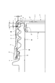
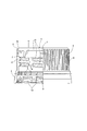
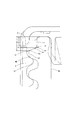
本発明の一実施の形態に係る容器が備えるキャップは、図1に示すように、容器口部Mに螺着するピルファープルーフキャップである。すなわち、天壁1の外周部から垂下するスカート壁2と、破断可能なブリッジ3を介してスカート壁2の下部に連なるタンパーエビデンスバンド(以下、バンドと略称する)4とを備え、バンド4の内周側にはフラップ5が延び、フラップ5は容器口部Mの環状突起M1に係合可能である。従って、開栓時に、天壁1及びスカート壁2を有するキャップ本体6は容器口部Mから離脱するが、バンド4は容器口部Mにとどまり、キャップ本体6(スカート壁2)とバンド4とをつなぐブリッジ3は破断する。
As shown in FIG. 1, the cap included in the container according to the embodiment of the present invention is a pill fur proof cap that is screwed into the container mouth M. That is, a
本キャップはまた、合成樹脂製のキャップであって、容器口部Mを密封するパッキン7をキャップ本体6内に備えた所謂2ピースキャップである。すなわち、キャップ本体6とバンド4は合成樹脂からなる一体成形品であり、パッキン7はこれとは別体の合成樹脂製の部材である。尚、パッキン7は、容器口部Mの上面に当接する円盤状の天板7aと、天板7aから垂下し容器口部Mの内周面に密接する中足7bと、天板7aの外周側から下方へと湾曲し容器口部Mの外周面に密接するサイドシール部7cとを有する(図1参照)。
The cap is also a so-called two-piece cap made of a synthetic resin and provided with a
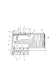
そして、本キャップは、容器の天面側から散水するだけのパストライザーによる洗浄に対応するように、スカート壁2の上部に位置する洗浄孔(洗浄液導入孔)8と、バンド4の内周側に位置する排出口(洗浄液導出孔)9とを有する(図1、図2、図4参照)。
The cap has a cleaning hole (cleaning liquid introduction hole) 8 located at the upper part of the
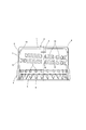
洗浄孔8は、スカート壁2の周方向に延びスカート壁2を貫通するスリット状の孔であり、スカート壁2の周方向に間隔をおいて(等ピッチで)四つ存在する(図2、図4参照)。
The
ここで、洗浄孔8は、スカート壁2の周方向に1〜6mmの範囲で延び、換言すれば、洗浄孔8の幅w(図2参照)は1〜6mmである。幅wが1mm未満であると洗浄液が洗浄孔8からキャップ内に入り難くなり、幅wが6mm超であると、洗浄孔8からの微小な異物の侵入、見栄えや強度の低下等が問題化する恐れがある。
Here, the
洗浄孔8はまた、キャップが容器口部Mに螺着した状態(装着状態)にあるときに、容器口部Mの上端から下方に1mm以上離れた範囲に位置するように存在し、換言すれば、洗浄孔8の容器口部Mの上端からの距離d(図1参照)は、1mm以上の範囲にある。
The
ここで、距離dが1mm未満であると、パッキン7が洗浄孔8を塞ぎ洗浄を阻害する可能性がある。また、図1、図2、図4に示すように、スカート壁2の内周面の上部はパッキン押さえブロック(以下、ブロックと略称する)10が占めており、距離dが1mm未満であると、洗浄孔8がこのブロック10を貫くようにして形成されてしまう可能性、ひいては、キャップのタンパーエビデンス機能を損失する可能性を高めることになる。つまり、例えばスカート壁2の一部を外側からカッターで切断して洗浄孔8を形成したときに、スカート壁2の内周面側に所謂バリが出来る可能性がある。そして、洗浄孔8がブロック10を貫く位置にあれば、バリはブロック10の内周面に形成されることになる。ブロック10の内周面は小径であり、しかもパッキン7のすぐ近くにあるので、ブロック10の内周面にバリが存在すると、開栓の際にそのバリがパッキン7に当たり、パッキン7がバリによって持ち上がる可能性は高く、この場合、タンパーエビデンス機能が損なわれる可能性も高くなる。
Here, if the distance d is less than 1 mm, the
尚、距離dが1mm以上であれば、洗浄孔8は、スカート壁2が容器口部Mに螺着しパッキン7が容器口部Mを密封する装着状態にあるときにパッキン7のサイドシール部7cの下端よりも下方に位置し(図1参照)、さらにはブロック10よりも下方に位置することになり、ブロック10の下方では、スカート壁2の内周面とパッキン7のサイドシール部7cの外周面との間に0.2mm以上のクリアランスA(図1、図2参照)が存在するので、突出量は高々0.1mm程度のバリが開栓の際にパッキン7を持ち上げることは無く、タンパーエビデンス機能は確実に保証されることになる。
If the distance d is 1 mm or more, the
また、図7に示すように、容器口部Mは、容器口部Mの上端から下方に距離D(図1も参照)として1.7mm離れた位置に螺子切り始め部11を有し、容器口部Mの上端から下方に距離D’として2.2mm離れた位置に洗浄限界部11’を有する。ここで、螺子切り始め部11は、容器口部Mの上端部の外周面上を通る鉛直線L1と、容器口部Mにおいて最上に位置する螺子山の上面側に設けられた傾斜角度が一定の傾斜面上を通る傾斜線L2との交点P1と同じ高さ位置に存在する。また、洗浄限界部11’は、容器口部Mにおいて最上に位置する螺子山の外周面上を鉛直方向に通る鉛直線L3と傾斜線L2との交点P2と同じ高さ位置に存在する。そして、距離dが距離D(1.7mm)以内であれば、容器口部Mの上部やスカート壁2の上部にまで洗浄液が行き渡り、充分な洗浄を行える。さらに、距離dが距離D(1.7mm)超であっても距離D’(2.2mm)以内であれば、洗浄液は最上の螺子山の上面(傾斜線L2が通る面)によって上側に向かって流れるように案内され、容器口部Mの上部やスカート壁2の上部の洗浄を行えると考えられる。距離dが距離D’(2.2mm)超であると、容器口部Mの上部やスカート壁2の上部にまで洗浄液がうまく行き渡らず、充分な洗浄を行えない可能性がある。すなわち、本例の距離dは、1〜2.2mm(好ましくは1〜1.7mm)の範囲にある。
Further, as shown in FIG. 7, the container mouth portion M has a screw cutting
排出口9は、バンド4の下部の折り返し部分を切り欠いた形状を呈する孔であり、バンド4の周方向に間隔をおいて(等ピッチで)五つ存在する(図2〜図4参照)。
The
上記のように、洗浄孔8は四つであるのに対して、排出口9は五つであり、両者8,9の個数は異なる。そして、少なくとも一つの洗浄孔8は各排出口9の直上からスカート壁2の周方向に離れた位置にあるようにすれば、その洗浄孔8からキャップ本体6と容器口部Mとの間に入った洗浄液は、仮にストレートに流下しても、その直下には排出口9は存在しないので、キャップ外へ流出するまでの間に必ずバンド4の周方向にも流れることになり、それだけ洗浄液による洗浄効果は高まる。
As described above, the number of the cleaning holes 8 is four, whereas the number of the
例えば、本キャップを備えた容器の内容物が耐熱性を有する場合、パストライザーがその内部を通過するこの容器に浴びせるシャワー水(洗浄液)の温度は、その入口から出口に向かって徐々に下がり、入口付近では80℃前後、出口付近では30℃前後である。従って、パストライザーの入口付近では、本キャップは熱水を浴びて温まり、洗浄孔8は図5に示すように開いてシャワー水が入り易くなるので、洗浄孔8の幅wは1〜2mm程度であっても十分な洗浄を行える。加えて、シャワー水の粘性は高温ほど低くなり、斯かる高温のシャワー水がキャップと容器口部Mの間の隅々にまで行き渡るので、これによっても洗浄効果は高まることになる。また、容器がパストライザーの出口に近づくにつれ、シャワー水の温度は低下し、これに伴って洗浄孔8が狭まるとともにシャワー水の粘性が上がるため、シャワー水は本キャップ内へ入り難くなり、故に、水切り性が良好となる上、先にキャップ内に流入するほど汚れをより多く含むことになる粘性の比較的高い水は、後から流入する粘性の比較的低い水によって汚れと共に絡めとられるようにして洗い流され、排出口9から排出されることになるので、非常に効果的な洗浄を行える。
For example, when the contents of the container provided with the cap have heat resistance, the temperature of the shower water (cleaning liquid) that is applied to the container through which the path riser passes is gradually lowered from the inlet toward the outlet. It is around 80 ° C. near the entrance and around 30 ° C. near the exit. Therefore, in the vicinity of the entrance of the path riser, the cap is warmed with hot water, and the
また、本キャップを備えた容器の内容物が常温充填される炭酸水等である場合、この容器が浴びるシャワー水の温度は、内容物が耐熱性である上記の場合よりも低くなるが、キャップの洗浄孔8の幅wを6mm程度にしておくことにより、充分な洗浄を行える。
In addition, when the contents of the container equipped with the cap is carbonated water filled at room temperature, the temperature of the shower water bathed by the container is lower than in the above case where the contents are heat resistant. If the width w of the
なお、本発明は、上記の実施の形態に何ら限定されず、本発明の要旨を逸脱しない範囲において種々に変形して実施し得ることは勿論である。例えば、以下のような変形例を挙げることができる。 In addition, this invention is not limited to said embodiment at all, Of course, it can change and implement variously in the range which does not deviate from the summary of this invention. For example, the following modifications can be given.
洗浄孔8、排出口9の個数は、それぞれ4個、5個に限らず、種々に変更可能である。例えば、洗浄孔8の個数は2〜16個、好ましくは2〜8個とし、排出口9の個数は2〜8個、好ましくは4〜6個とすることができる。但し、洗浄性の観点から、両者8,9がそれぞれスカート壁2、バンド4の周方向に等間隔で複数位置していることが好ましい。また、洗浄孔8の直下に排出口9を設けないことが洗浄液の流域拡大による洗浄性向上の点で望ましいが、洗浄孔8を後加工で形成する関係上、排出口9に対する洗浄孔8の位置を特定して形成するのが困難な場合もある。そこで、そのような場合には、両者8,9の個数を互いに異ならせつつ、両者8,9を共に周方向に等間隔で設けるのが洗浄性の点では最も有効である。しかし、例えば、洗浄孔8、排出口9の何れか一方(例えば洗浄孔8)のみを周方向に等間隔(等ピッチ)で設け、他方(例えば排出口9)を周方向に等間隔とならないように(不等ピッチで)設けるようにしてもよく、両方を不等ピッチで設けてもよい。勿論、両者8,9の個数を等しくしつつ、両者8,9の位置を周方向にずらすようにしてもよい。
The number of the cleaning holes 8 and the
容器口部Mは、容器口部Mの上端から下方に1.7mmより離れた位置に螺子切り始め部11を有していてもよい。
The container mouth part M may have the screw cutting start
図1に示すように、本キャップのスカート壁2は、容器口部Mの雄ねじ部M2に螺合する雌ねじ部12を有し、この雌ねじ部12は、図4に示すように、スカート壁2の周方向に複数に分断された小片状の突起13からなり、隣り合う突起13間には洗浄液の通り道となる縦溝14が存在する。そこで、図4に示すように、複数の縦溝14が上下に連なっているような場合には、各縦溝14の直下から周方向に避けた位置に少なくとも一つの排出口9(望ましくは各排出口9)を設けるようにすれば、洗浄液の流域を広げることができ、それだけ洗浄液による洗浄効果を高めることができる。また、複数の縦溝14が上下に並ばないように互いに周方向にずれるようにしても同様の効果が得られる。
As shown in FIG. 1, the
図6は参考例を示し、このキャップは、キャップ本体6が容器口部Mを密閉する中足(インナーリング)1aと外足(アウターリング)1bとを有する1ピースキャップである。すなわち、中足1a、外足1bはそれぞれパッキン7の中足7b、サイドシール部7cに相当する部位である。尚、1ピースキャップである場合、バリによるパッキン7の持ち上げの問題は生じないので、洗浄孔8の高さ位置を規定する距離dを上記範囲(1〜2.2mm)外に設定することができ、ブロック10も不要となる。
FIG. 6 shows a reference example, and this cap is a one-piece cap having a middle leg (inner ring) 1a and an outer leg (outer ring) 1b in which the
また、図2に示すスカート壁2の外面の全周にわたるローレット15の山数は120個であるが、この山数や山の高さ等も任意に変更可能である。例えば、参考例の1ピースキャップの場合には、一般的に開栓トルクが2ピースキャップよりも大となるので、力を掛けやすいように山を高くしつつローレット15の山数を120未満としてもよく、図6には山数を60とした例を示している。
In addition, although the number of
フラップ5は、拡径方向に弾性変形可能であり、容器口部Mに対するキャップの装着時には弾性変形して環状突起M1を乗り越え、乗り越えた後は弾性復帰してこの環状突起M1に係止するものであればよく、図2〜図4には連続蛇腹状のフラップ5を示している。、図6の参考例では、フラップ5が周方向に間隔をおいて並ぶ複数の係止片5aからなり、この場合、隣り合う係止片5aの間隔が排出口9となる。
The
なお、上記変形例どうしを適宜組み合わせてもよいことはいうまでもない。
Needless to say, the above modifications may be combined as appropriate.
Claims (7)
前記洗浄孔は、前記スカート壁が容器口部に螺着し前記パッキンが容器口部を密封する装着状態にあるときに前記パッキンの前記サイドシール部の下端よりも下方に位置するよう構成されている一方、前記パッキン押さえブロックは、前記パッキンの前記サイドシール部の下端よりも下方にまで延設されており、さらに、前記洗浄孔は、前記パッキン押さえブロックよりも下方に位置している2ピースキャップであって、
少なくとも一つの前記洗浄孔は前記各排出口の直上からスカート壁の周方向に離れた位置にあるとともに、
前記洗浄孔のバリが開栓の際に前記パッキンを持ち上げることが無いように前記洗浄孔は、前記スカート壁が容器口部に螺着し前記パッキンが容器口部を密封する装着状態にあるときに前記パッキン押さえブロックより下部のスカート壁内周面と前記パッキンの前記サイドシール部の外周面との間にクリアランスが存在する部位に位置することを特徴とするキャップ。 A skirt wall that hangs down from the outer peripheral portion of the top wall and is screwed into the container mouth, a plurality of cleaning holes for introducing a cleaning liquid positioned at the top of the skirt wall, and a plurality of cleaning liquid outlets positioned below the skirt wall The cap body having the top wall and the skirt wall is provided with a packing that is separate from the cap body and seals the container mouth portion, and the packing includes the container mouth. A side seal portion that is in close contact with the outer peripheral surface of the portion, and further, the skirt wall has a packing holding block that is located above the cleaning hole and occupies the upper portion of the inner peripheral surface of the skirt wall, The inner diameter of the inner peripheral surface of the packing pressing block is configured to be smaller than the inner diameter of the inner peripheral surface of the skirt wall below the packing pressing block ,
The cleaning hole is configured to be positioned below a lower end of the side seal portion of the packing when the skirt wall is screwed to the container mouth portion and the packing is in a state of sealing the container mouth portion. On the other hand, the packing holding block extends to a position lower than the lower end of the side seal portion of the packing, and the cleaning hole is located below the packing holding block. A cap,
At least one of the cleaning holes is located at a position away from the top of each of the discharge ports in the circumferential direction of the skirt wall;
The cleaning hole is in a mounted state in which the skirt wall is screwed into the container mouth and the packing seals the container mouth so that the burr of the cleaning hole does not lift the packing when the stopper is opened. Further, the cap is characterized in that it is located at a portion where a clearance exists between the inner peripheral surface of the skirt wall below the packing pressing block and the outer peripheral surface of the side seal portion of the packing .
A container comprising the cap according to any one of claims 1 to 6 .
Applications Claiming Priority (1)
| Application Number | Priority Date | Filing Date | Title |
|---|---|---|---|
| PCT/JP2011/070936 WO2013038515A1 (en) | 2011-09-14 | 2011-09-14 | Cap and container |
Publications (2)
| Publication Number | Publication Date |
|---|---|
| JPWO2013038515A1 JPWO2013038515A1 (en) | 2015-03-23 |
| JP6060080B2 true JP6060080B2 (en) | 2017-01-11 |
Family
ID=47882776
Family Applications (1)
| Application Number | Title | Priority Date | Filing Date |
|---|---|---|---|
| JP2013533393A Active JP6060080B2 (en) | 2011-09-14 | 2011-09-14 | Caps and containers |
Country Status (3)
| Country | Link |
|---|---|
| JP (1) | JP6060080B2 (en) |
| CN (1) | CN103857599B (en) |
| WO (1) | WO2013038515A1 (en) |
Families Citing this family (2)
| Publication number | Priority date | Publication date | Assignee | Title |
|---|---|---|---|---|
| CN105883180A (en) * | 2015-10-20 | 2016-08-24 | 江苏中饮机械有限公司 | Sanitary bottle cap |
| CN107487084B (en) * | 2016-06-10 | 2020-08-14 | 精工爱普生株式会社 | Ink replenishing container |
Family Cites Families (14)
| Publication number | Priority date | Publication date | Assignee | Title |
|---|---|---|---|---|
| CA1290281C (en) * | 1986-04-25 | 1991-10-08 | Joseph J. Bullock, Iii | Plastic bottle cap having foil neck seal |
| JPH0454119Y2 (en) * | 1987-11-20 | 1992-12-18 | ||
| JPH101158A (en) * | 1996-06-12 | 1998-01-06 | Shibasaki Seisakusho:Kk | Cap with washing holes for bottle mouth and manufacture thereof and washing method for bottle mouth |
| JP3136109B2 (en) * | 1996-11-22 | 2001-02-19 | 日本山村硝子株式会社 | Synthetic resin cap and manufacturing method thereof |
| US6981602B2 (en) * | 1997-08-01 | 2006-01-03 | Portola Packaging, Inc. | Tamper evident bottle cap |
| JP3967445B2 (en) * | 1998-01-28 | 2007-08-29 | 日本クラウンコルク株式会社 | Synthetic resin container lid with cut and method of forming cut |
| JP3213842B2 (en) * | 1998-09-04 | 2001-10-02 | 日本クラウンコルク株式会社 | Container cleaning method |
| US6253940B1 (en) * | 1999-04-28 | 2001-07-03 | Owens-Illinois Closure Inc. | Tamper-indicating closure and method of manufacture |
| KR100501569B1 (en) * | 1999-07-05 | 2005-07-18 | 가부시키가이샤 아르코아 크로자 시스템즈 | Cap with cleaning mechanism, a manufacturing method thereof, and a cleaning method for a container opening |
| JP4504794B2 (en) * | 2004-12-03 | 2010-07-14 | 日本山村硝子株式会社 | Cap, content filling container and cleaning method for content filling container |
| JP5171011B2 (en) * | 2006-11-02 | 2013-03-27 | 日本クラウンコルク株式会社 | Cap with inner plug |
| EP2241513B1 (en) * | 2008-01-31 | 2013-08-07 | Nihon Yamamura Glass Co., Ltd. | Use of a cap for a container containing a carbonated beverage |
| JP5459972B2 (en) * | 2008-03-27 | 2014-04-02 | 日本クロージャー株式会社 | Plastic cap |
| CN202295663U (en) * | 2011-09-14 | 2012-07-04 | 日本山村硝子株式会社 | Cover and container |
-
2011
- 2011-09-14 CN CN201180072831.4A patent/CN103857599B/en active Active
- 2011-09-14 JP JP2013533393A patent/JP6060080B2/en active Active
- 2011-09-14 WO PCT/JP2011/070936 patent/WO2013038515A1/en active Application Filing
Also Published As
| Publication number | Publication date |
|---|---|
| CN103857599B (en) | 2016-10-26 |
| CN103857599A (en) | 2014-06-11 |
| WO2013038515A1 (en) | 2013-03-21 |
| JPWO2013038515A1 (en) | 2015-03-23 |
Similar Documents
| Publication | Publication Date | Title |
|---|---|---|
| JP6060080B2 (en) | Caps and containers | |
| AU3018800A (en) | Tamper-indicating closure and method of manufacture | |
| JP4909550B2 (en) | Polyester resin bottle | |
| ITMO980237A1 (en) | "BOTTLE WITH SAFETY CAP, PARTICULARLY FOR PHARMACEUTICAL PRODUCTS" | |
| JPH0454119Y2 (en) | ||
| JP4799145B2 (en) | Plastic container lid | |
| JP4504794B2 (en) | Cap, content filling container and cleaning method for content filling container | |
| CN202295663U (en) | Cover and container | |
| JP5271650B2 (en) | Plastic cap for beverage containers | |
| RU2344059C2 (en) | Protected device for corking bottles | |
| JP5019465B2 (en) | Plastic cap | |
| JP6688686B2 (en) | Synthetic resin container lid | |
| JP6539011B1 (en) | Synthetic resin cap and container | |
| JP5171011B2 (en) | Cap with inner plug | |
| JP5973764B2 (en) | Container lid | |
| JP4104113B2 (en) | Cleaning the inner surface of the cap after plugging | |
| JP4980940B2 (en) | Plastic cap | |
| JP4884272B2 (en) | Resin container lid | |
| JP2003261158A (en) | Vessel body, and combination of vessel body with synthetic resin lid | |
| JP5086057B2 (en) | Plastic cap with improved cleanability | |
| JP5869286B2 (en) | lid | |
| JP5459972B2 (en) | Plastic cap | |
| CN109715513A (en) | Capping | |
| JP2009102074A (en) | Cleaning method between container body and container lid | |
| JP2012051650A (en) | Method of manufacturing spout stopper |
Legal Events
| Date | Code | Title | Description |
|---|---|---|---|
| A131 | Notification of reasons for refusal |
Free format text: JAPANESE INTERMEDIATE CODE: A131 Effective date: 20150507 |
|
| A521 | Request for written amendment filed |
Free format text: JAPANESE INTERMEDIATE CODE: A523 Effective date: 20150616 |
|
| A131 | Notification of reasons for refusal |
Free format text: JAPANESE INTERMEDIATE CODE: A131 Effective date: 20160107 |
|
| A521 | Request for written amendment filed |
Free format text: JAPANESE INTERMEDIATE CODE: A523 Effective date: 20160223 |
|
| A02 | Decision of refusal |
Free format text: JAPANESE INTERMEDIATE CODE: A02 Effective date: 20160804 |
|
| A521 | Request for written amendment filed |
Free format text: JAPANESE INTERMEDIATE CODE: A523 Effective date: 20161006 |
|
| A521 | Request for written amendment filed |
Free format text: JAPANESE INTERMEDIATE CODE: A523 Effective date: 20161020 |
|
| A911 | Transfer to examiner for re-examination before appeal (zenchi) |
Free format text: JAPANESE INTERMEDIATE CODE: A911 Effective date: 20161107 |
|
| TRDD | Decision of grant or rejection written | ||
| A01 | Written decision to grant a patent or to grant a registration (utility model) |
Free format text: JAPANESE INTERMEDIATE CODE: A01 Effective date: 20161201 |
|
| A61 | First payment of annual fees (during grant procedure) |
Free format text: JAPANESE INTERMEDIATE CODE: A61 Effective date: 20161212 |
|
| R150 | Certificate of patent or registration of utility model |
Ref document number: 6060080 Country of ref document: JP Free format text: JAPANESE INTERMEDIATE CODE: R150 |
|
| R250 | Receipt of annual fees |
Free format text: JAPANESE INTERMEDIATE CODE: R250 |
|
| R250 | Receipt of annual fees |
Free format text: JAPANESE INTERMEDIATE CODE: R250 |
|
| R250 | Receipt of annual fees |
Free format text: JAPANESE INTERMEDIATE CODE: R250 |
|
| R250 | Receipt of annual fees |
Free format text: JAPANESE INTERMEDIATE CODE: R250 |
|
| R250 | Receipt of annual fees |
Free format text: JAPANESE INTERMEDIATE CODE: R250 |