JP6059975B2 - Wire harness and method of manufacturing wire harness - Google Patents
Wire harness and method of manufacturing wire harness Download PDFInfo
- Publication number
- JP6059975B2 JP6059975B2 JP2012270405A JP2012270405A JP6059975B2 JP 6059975 B2 JP6059975 B2 JP 6059975B2 JP 2012270405 A JP2012270405 A JP 2012270405A JP 2012270405 A JP2012270405 A JP 2012270405A JP 6059975 B2 JP6059975 B2 JP 6059975B2
- Authority
- JP
- Japan
- Prior art keywords
- plastic corrugated
- corrugated sheet
- wire
- wire bundle
- sheet
- Prior art date
- Legal status (The legal status is an assumption and is not a legal conclusion. Google has not performed a legal analysis and makes no representation as to the accuracy of the status listed.)
- Active
Links
- 238000004519 manufacturing process Methods 0.000 title claims description 8
- 239000004033 plastic Substances 0.000 claims description 145
- 210000000078 claw Anatomy 0.000 claims description 11
- 238000005520 cutting process Methods 0.000 claims description 7
- 238000003466 welding Methods 0.000 claims description 7
- 239000000463 material Substances 0.000 description 9
- 239000000853 adhesive Substances 0.000 description 4
- 230000001070 adhesive effect Effects 0.000 description 4
- 239000004820 Pressure-sensitive adhesive Substances 0.000 description 3
- 239000010410 layer Substances 0.000 description 3
- JOYRKODLDBILNP-UHFFFAOYSA-N Ethyl urethane Chemical compound CCOC(N)=O JOYRKODLDBILNP-UHFFFAOYSA-N 0.000 description 2
- 239000004743 Polypropylene Substances 0.000 description 2
- 238000000034 method Methods 0.000 description 2
- 238000003825 pressing Methods 0.000 description 2
- 239000011347 resin Substances 0.000 description 2
- 229920005989 resin Polymers 0.000 description 2
- 239000012790 adhesive layer Substances 0.000 description 1
- 239000002390 adhesive tape Substances 0.000 description 1
- 239000006261 foam material Substances 0.000 description 1
- 238000009434 installation Methods 0.000 description 1
- 238000005192 partition Methods 0.000 description 1
- 239000002985 plastic film Substances 0.000 description 1
- -1 polypropylene Polymers 0.000 description 1
- 229920001155 polypropylene Polymers 0.000 description 1
- 238000000926 separation method Methods 0.000 description 1
- 230000009466 transformation Effects 0.000 description 1
Images


Landscapes
- Connection Of Plates (AREA)
- Details Of Indoor Wiring (AREA)
- Installation Of Indoor Wiring (AREA)
Description
本発明は、被取付体上の直線状の配索経路に組み付けられるワイヤハーネスに関する。 The present invention relates to a wire harness assembled to a linear wiring path on an attached body.
車両の車体に配索されるワイヤハーネスは、車体への組み付け作業性の向上や、電線の保護を目的として、ワイヤハーネスを構成する電線束を、スパイラルチューブやコルゲートチューブ、あるいは樹脂製スリーブ等の外装材に収容支持した構造とすることが多い。 For the purpose of improving assembly workability to the vehicle body and protecting the electric wires, the wire harness routed in the vehicle body is made up of a bundle of wires, such as a spiral tube, a corrugated tube, or a resin sleeve. In many cases, the structure is housed and supported by an exterior material.
しかし、これらのスパイラルチューブやコルゲートチューブ、あるいは樹脂製スリーブ等の外装材は、比較的に高額であり、ワイヤハーネスの高額化を招く要因となった。 However, exterior materials such as these spiral tubes, corrugated tubes, or resin sleeves are relatively expensive, which has led to an increase in the cost of wire harnesses.
そこで、下記特許文献1では、組み付け作業性が良好で、且つ安価なワイヤハーネスとして、図6に示すワイヤハーネスを開示している。 Therefore, in Patent Document 1 below, a wire harness shown in FIG. 6 is disclosed as an inexpensive wire harness that has good assembly workability.
このワイヤハーネス100は、電線束110を、一対の片面粘着シート120で挟んで支持する。
This
片面粘着シート120は、PP(ポリプロピレン)発泡材からなるシート基材121と、このシート基材121の表面に積層される表面材122と、シート基材121の裏面に積層される粘着剤層123と、を備えた3層構造のものである。
The single-sided
電線束110を挟む一対の片面粘着シート120は、互いの粘着剤層123を対向させて配置され、面接触する互いの粘着剤層123相互の接着により、電線束110を保持する。
A pair of single-sided pressure-sensitive
また、一方(図6では、下側)の片面粘着シート120には、クランプ130を支持するクランプ取付穴125が貫通形成されている。
In addition, a
クランプ130は、クランプ取付穴125よりも大径の板状に形成された基端部131と、この基端部131から延出する係止片部132と、を備えている。係止片部132は、クランプ取付穴125を挿通可能な中心軸部132aと、この中心軸部132aの先端から基端側に斜めに延出した係止爪132bと、を具備したものである。係止爪132bは、クランプ取付穴125を通過する際には、中心軸部132a側に撓み変形してクランプ取付穴125を通過し、クランプ取付穴125を通過すると、撓みが戻って、係止爪132bの先端がクランプ取付穴125よりも外側に広がる。
The
ところが、特許文献1のワイヤハーネス100の場合、片面粘着シート120の剛性が乏しいため、ワイヤハーネス自体では直線形状を維持することができず、例えば、車体の垂直壁部や天井部に設定された直線状の配索経路に組み付ける際、一端側を配索経路上に押さえ付けても、他端側が垂れ下がって配索経路から離れてしまい、組み付けが難しいという問題が生じる。
However, in the case of the
そこで、本発明の目的は、上記課題を解消することに係り、直線状の配索経路への組み付けを容易にすることができ、しかも、安価に製造することができるワイヤハーネス及びワイヤハーネスの製造方法を提供することにある。 An object of the present invention relates to solve the above problems, the assembling of the linear installation path can be easy and the production of the wire harness and the wire harness can be manufactured at a low cost It is to provide a method .
本発明の前述した目的は、下記の構成により達成される。
(1) 被取付体上の直線状の配索経路に敷設される電線束と、この電線束を前記配索経路に整合する直線状に支持する電線支持部材と、を備え、
前記電線支持部材は、
前記中空部の延在方向が前記配索経路の延在方向に一致するように裁断されて、その一方の面の上に前記電線束が載置される第1のプラスチック段ボールシートと、
該第1のプラスチック段ボールシート上の前記電線束の上を横断すると共に前記電線束の両側にはみ出した両端部が前記第1のプラスチック段ボールシートの表面に面接触可能な寸法に裁断された第2のプラスチック段ボールシートと、を備え、
前記第1のプラスチック段ボールシートとの間に前記電線束を挟んだ状態に前記第1のプラスチック段ボールシートの上に配置した前記第2のプラスチック段ボールシートの前記両端部を前記第1のプラスチック段ボールシートの表面に面接触するように固定することで、前記第1のプラスチック段ボールシート上に載置された前記電線束を前記第1のプラスチック段ボールシートに固定することを特徴とするワイヤハーネス。
The above-described object of the present invention is achieved by the following configuration.
(1) An electric wire bundle laid in a linear wiring path on the mounted body, and an electric wire support member that supports the electric wire bundle in a straight line matching the wiring path,
The wire support member is
A first plastic corrugated sheet in which the extending direction of the hollow portion is cut so as to coincide with the extending direction of the routing path, and the wire bundle is placed on one surface thereof;
A second cross section that crosses over the wire bundle on the first plastic corrugated sheet and that has both ends protruding to both sides of the wire bundle is cut to a size that allows surface contact with the surface of the first plastic corrugated sheet. A plastic corrugated sheet, and
The both ends of the second plastic corrugated sheet placed on the first plastic corrugated sheet with the wire bundle sandwiched between the first plastic corrugated sheet and the first plastic corrugated sheet. A wire harness characterized in that the wire bundle placed on the first plastic corrugated sheet is fixed to the first plastic corrugated sheet by being fixed so as to be in surface contact with the surface of the wire.
(2) 被取付体上の直線状の配索経路に敷設される電線束と、この電線束を前記配索経路に整合する直線状に支持する電線支持部材と、を備え、
前記電線支持部材は、
中空部の延在方向が前記配索経路の延在方向に一致するように裁断されて、その一方の面の上に前記電線束が載置される第1のプラスチック段ボールシートと、
該第1のプラスチック段ボールシート上の前記電線束の上を横断すると共に前記電線束の両側にはみ出した両端部が前記第1のプラスチック段ボールシートの表面に面接触可能な寸法に裁断された第2のプラスチック段ボールシートと、を備え、
前記第1のプラスチック段ボールシートとの間に前記電線束を挟んだ状態に前記第1のプラスチック段ボールシートの上に配置した前記第2のプラスチック段ボールシートの前記両端部を前記第1のプラスチック段ボールシートに溶着させることで、前記第1のプラスチック段ボールシート上に載置された前記電線束を前記第1のプラスチック段ボールシートに固定することを特徴とするワイヤハーネス。
(2) An electric wire bundle laid on a straight wiring path on the attached body, and an electric wire support member that supports the electric wire bundle in a straight line matching the wiring path,
The wire support member is
Is cut to the extending direction of the middle hollow portion coincides with the extending direction of the wiring path, a first plastic cardboard sheet in which the wire bundle is placed on the one surface,
A second cross section that crosses over the wire bundle on the first plastic corrugated sheet and that has both ends protruding to both sides of the wire bundle is cut to a size that allows surface contact with the surface of the first plastic corrugated sheet. A plastic corrugated sheet, and
The both ends of the second plastic corrugated sheet placed on the first plastic corrugated sheet with the wire bundle sandwiched between the first plastic corrugated sheet and the first plastic corrugated sheet. A wire harness characterized in that the wire bundle placed on the first plastic corrugated sheet is fixed to the first plastic corrugated sheet by being welded to the first plastic corrugated sheet.
(3) 上記(1)又は上記(2)に記載のワイヤハーネスにおいて、
前記電線支持部材を前記配索経路に固定する固定手段をさらに備え、
前記固定手段は、被取付体上の配索経路に載置される前記プラスチック段ボールシートの一面に埋設状態に固定される基端部と、該基端部から延出して前記配索経路上の取付穴に挿入されると該取付穴に係合する係止爪と、を備えたクランプであることを特徴とするワイヤハーネス。
(4) プラスチック段ボールシートを中空部の延在方向が配索経路の延在方向に一致するように裁断して電線支持部材とし、
前記配索経路に固定する固定手段としてのクランプを前記裁断前または前記裁断後に取付け、
前記電線支持部材の一方の面の上に電線束を載置し、
前記電線束を前記配索経路に整合する直線状に前記電線支持部材に支持したことを特徴とするワイヤハーネスの製造方法。
(5) 前記プラスチック段ボールシート上の前記電線束の上を横断し、且つ、前記電線束の両側にはみ出した両端部が前記プラスチック段ボールシートの表面に面接触可能な寸法にもう1つのプラスチック段ボールシートを裁断し、
前記もう1つのプラスチック段ボールシートの両端部は、それぞれ溶着させることで、前記電線支持部材に固定することを特徴とする上記(4)に記載のワイヤハーネスの製造方法。
( 3 ) In the wire harness described in (1) or (2) above ,
A fixing means for fixing the wire support member to the routing path;
The fixing means includes a base end portion fixed in an embedded state on one surface of the plastic corrugated sheet placed on the routing path on the attachment body, and a base end portion extending from the base end portion on the routing path. A wire harness comprising: a locking claw that engages with the mounting hole when inserted into the mounting hole.
(4) The plastic corrugated cardboard sheet is cut so that the extending direction of the hollow portion matches the extending direction of the routing path to obtain an electric wire support member,
A clamp as a fixing means for fixing to the routing path is attached before or after the cutting,
A wire bundle is placed on one surface of the wire support member,
A method of manufacturing a wire harness, characterized in that the wire bundle is supported by the wire support member in a straight line matching the wiring path.
(5) Another plastic corrugated sheet having a dimension that traverses over the wire bundle on the plastic corrugated sheet and has both ends protruding from both sides of the wire bundle in surface contact with the surface of the plastic corrugated sheet. Cutting
Both ends of the other plastic corrugated cardboard sheet are fixed to the electric wire support member by welding, respectively. The method for manufacturing a wire harness according to (4) above,
上記(1)又は上記(2)の構成によれば、電線束を直線状に支持する電線支持部材に使用するプラスチック段ボールシートは、中空部の延在方向に高い剛性を持つ。そのため、例えば、車体の垂直壁部や天井部に設定された直線状の配索経路に組み付ける際、ワイヤハーネスの略全長を直線状に保ったまま配索経路に位置決めすることができ、直線状の配索経路への組み付けを容易にすることができる。しかも、プラスチック段ボールシートは、例えばコルゲートチューブやウレタン製の外装材と比較して安価であるため、ワイヤハーネスを安価に製造することができる。 According to the configuration of the above (1) or (2) , the plastic corrugated cardboard sheet used for the electric wire support member that linearly supports the electric wire bundle has high rigidity in the extending direction of the hollow portion. Therefore, for example, when assembling to a straight wiring route set on the vertical wall or ceiling of the vehicle body, the wire harness can be positioned in the wiring route while maintaining the substantially entire length of the wire harness. Can be easily assembled to the routing route. And since a plastic corrugated cardboard sheet is cheap compared with a corrugated tube or the exterior material made from urethane, for example, a wire harness can be manufactured cheaply.
加えて、上記(1)又は上記(2)の構成によれば、第1のプラスチック段ボールシートとの間に電線束を挟む第2のプラスチック段ボールシートは、第1のプラスチック段ボールシートと面接触する両端部が第1のプラスチック段ボールシートに溶着されて、第2のプラスチック段ボールシート自体がしっかりと第1のプラスチック段ボールシートに固定されると共に、電線束をしっかりと第1のプラスチック段ボールシートに固定することができる。 In addition , according to the configuration of the above (1) or (2), the second plastic corrugated sheet sandwiching the electric wire bundle with the first plastic corrugated sheet is in surface contact with the first plastic corrugated sheet. Both ends are welded to the first plastic corrugated sheet, the second plastic corrugated sheet itself is firmly fixed to the first plastic corrugated sheet, and the wire bundle is firmly fixed to the first plastic corrugated sheet. be able to.
そして、第2のプラスチック段ボールシートを第1のプラスチック段ボールシートとは別体とすることで、これらの第1のプラスチック段ボールシート及び第2のプラスチック段ボールシートは、何れも、裁断形状が単純な長方形になり、大型のプラスチック段ボールシートから板取りする際の歩留まりを向上させることができる。 Then, by making the second plastic corrugated sheet separate from the first plastic corrugated sheet, each of the first plastic corrugated sheet and the second plastic corrugated sheet is a rectangle with a simple cutting shape. Thus, it is possible to improve the yield when cutting from a large plastic corrugated cardboard sheet.
上記(3)の構成によれば、電線束を支持しているプラスチック段ボールシートの一面を被取付体上の配索経路に押し当てて、前記一面に突出しているクランプの係止爪を、配索経路に装備されている取付穴に係合させると、ワイヤハーネスが被取付体上の配索経路に固定された状態になる。即ち、ワイヤハーネスの被取付体上の配索経路への組み付け作業は、プラスチック段ボールシートの一面を被取付体上の配索経路に押し当てる操作だけで済み、組み付け作業を容易にすることができる。 According to the configuration of ( 3 ) above, the one surface of the plastic corrugated cardboard sheet supporting the wire bundle is pressed against the wiring path on the mounted body, and the locking claws of the clamp protruding on the one surface are arranged. When engaged with the mounting hole provided in the cable path, the wire harness is fixed to the cable path on the mounted body. That is, the work of assembling the wire harness to the routing path on the mounted body is only an operation of pressing one surface of the plastic corrugated cardboard sheet against the routing path on the mounted body, and the mounting work can be facilitated. .
本発明によるワイヤハーネス及びワイヤハーネスの製造方法によれば、直線状の配索経路への組み付けを容易にすることができ、しかも、安価に製造することができる。 According to the wire harness and the method of manufacturing the wire harness according to the present invention, it is possible to easily assemble the wire harness into the linear routing route and to manufacture the wire harness at a low cost.
以上、本発明について簡潔に説明した。更に、以下に説明される発明を実施するための形態(以下、「実施形態」という。)を添付の図面を参照して通読することにより、本発明の詳細は更に明確化されるであろう。 The present invention has been briefly described above. Further, the details of the present invention will be further clarified by reading through a mode for carrying out the invention described below (hereinafter referred to as “embodiment”) with reference to the accompanying drawings. .
以下、本発明に係るワイヤハーネスの好適な実施形態について、図面を参照して詳細に説明する。 Hereinafter, a preferred embodiment of a wire harness according to the present invention will be described in detail with reference to the drawings.
[第1実施形態]
図1〜図3は本発明に係るワイヤハーネスの第1実施形態を示したもので、図1は本発明の第1実施形態のワイヤハーネスの平面図、図2は図1に示したワイヤハーネスの要部の拡大斜視図、図3は図1に示したワイヤハーネスの裏面図である。
[First Embodiment]
1 to 3 show a first embodiment of a wire harness according to the present invention, FIG. 1 is a plan view of the wire harness according to the first embodiment of the present invention, and FIG. 2 is a wire harness shown in FIG. FIG. 3 is a rear view of the wire harness shown in FIG. 1.
この第1実施形態のワイヤハーネス1は、不図示の被取付体上の直線状の配索経路に敷設される電線束10と、この電線束10を配索経路に整合する直線状に支持する電線支持部材20と、該電線支持部材20を前記配索経路に固定する固定手段としてのクランプ30と、を備える。
The wire harness 1 according to the first embodiment supports an
本実施形態のワイヤハーネス1が組み付けられる被取付体は、例えば、車両の車体パネル等である。また、電線束10は、複数の電線が平面状に結合されたフラットケーブルである。
The attached body to which the wire harness 1 of this embodiment is assembled is, for example, a vehicle body panel or the like of a vehicle. The
本実施形態における電線支持部材20には、第1のプラスチック段ボールシート21と、複数の第2のプラスチック段ボールシート22と、を使用している。
A first plastic
第1のプラスチック段ボールシート21及び第2のプラスチック段ボールシート22は、所定の離間距離で平行に配列されたプラスチックシート相互を、一定ピッチで配列されるプラスチック製の仕切り壁あるいは波板で結合した構造のもので、横断面は複数の中空部が一列に並ぶ構造を成している。このようなプラスチック段ボールシートは、各種の寸法のものが市販されており、市販のものから選択することができる。
The first plastic
第1のプラスチック段ボールシート21は、中空部の延在方向が前記配索経路の延在方向(図1の矢印X1方向)に一致するように裁断されて、その一方の面の上に電線束10が載置される。電線束10の長手方向と、第1のプラスチック段ボールシート21の中空部の延在方向とは、一致させる。また、図1に示すように、第1のプラスチック段ボールシート21の幅寸法W1は、電線束10の幅寸法W2よりも大きく設定されている。
The first plastic
第2のプラスチック段ボールシート22は、第1のプラスチック段ボールシート21とは別体である。この第2のプラスチック段ボールシート22は、図2に示すように、第1のプラスチック段ボールシート21上の電線束10の上を横断し、且つ、電線束10の両側にはみ出した両端部22aが第1のプラスチック段ボールシート21の表面に面接触可能な寸法に裁断されている。
The second
この第2のプラスチック段ボールシート22は、中空部の延在方向が、第1のプラスチック段ボールシート21に揃えられている。第2のプラスチック段ボールシート22は、第1のプラスチック段ボールシート21の長さ方向に適宜間隔をあけた複数箇所に、設けられる。本実施形態では、第2のプラスチック段ボールシート22の両端部は、それぞれ2箇所を溶着させることで、第1のプラスチック段ボールシート21に固定されている。
In the second plastic
本実施形態の場合、第1のプラスチック段ボールシート21との間に電線束10を挟んだ状態に第1のプラスチック段ボールシート21の上に配置した第2のプラスチック段ボールシート22の両端部22aを、第1のプラスチック段ボールシート21に溶着させることで、第1のプラスチック段ボールシート21上に載置された電線束10を第1のプラスチック段ボールシート21に固定する。図2及び図3における符号Y1は、それぞれ溶着箇所を示している。
In the case of the present embodiment, both
クランプ30は、図6に示したクランプ130と同様の構造のもので良く、図示はしていないが、被取付体上の配索経路に載置される第1のプラスチック段ボールシート21の一面(裏面)に埋設状態に固定される基端部と、該基端部から延出して前記配索経路上の取付穴に挿入されると該取付穴に係合する係止爪と、を備えたものである。
The
本実施形態のワイヤハーネス1の場合、電線束10を直線状に支持する電線支持部材20に使用するプラスチック段ボールシート21,22は、中空部の延在方向に高い剛性を持つ。そのため、例えば、車体の垂直壁部や天井部に設定された直線状の配索経路に組み付ける際、ワイヤハーネス1の略全長を直線状に保ったまま配索経路に位置決めすることができ、直線状の配索経路への組み付けを容易にすることができる。しかも、プラスチック段ボールシート21,22は、例えばコルゲートチューブやウレタン製の外装材と比較して安価であるため、ワイヤハーネス1を安価に製造することができる。
In the case of the wire harness 1 of the present embodiment, the plastic
また、本実施形態のワイヤハーネス1の場合、第1のプラスチック段ボールシート21との間に電線束10を挟む第2のプラスチック段ボールシート22は、第1のプラスチック段ボールシート21と面接触する両端部が第1のプラスチック段ボールシート21に溶着されて、第2のプラスチック段ボールシート22自体がしっかりと第1のプラスチック段ボールシート21に固定されると共に、電線束10をしっかりと第1のプラスチック段ボールシート21に固定することができる。
Further, in the case of the wire harness 1 of the present embodiment, the second plastic
そして、本実施形態のワイヤハーネス1では、第2のプラスチック段ボールシート22を第1のプラスチック段ボールシート21とは別体としている。そのため、これらの第1のプラスチック段ボールシート21及び第2のプラスチック段ボールシート22は、何れも、裁断形状が単純な長方形になり、大型のプラスチック段ボールシートから板取りする際の歩留まりを向上させることができる。
In the wire harness 1 of the present embodiment, the second
更に、本実施形態のワイヤハーネス1では、電線束10を支持しているプラスチック段ボールシート21の一面(裏面)を被取付体上の配索経路に押し当てて、第1のプラスチック段ボールシート21の一面に突出しているクランプ30の係止爪を、配索経路に装備されている取付穴に係合させると、ワイヤハーネス1が被取付体上の配索経路に固定された状態になる。即ち、ワイヤハーネス1の被取付体上の配索経路への組み付け作業は、プラスチック段ボールシート21の一面を被取付体上の配索経路に押し当てる操作だけで済み、組み付け作業を容易にすることができる。
Furthermore, in the wire harness 1 of the present embodiment, one surface (back surface) of the plastic
[第2実施形態]
図4及び図5は本発明に係るワイヤハーネス1の第2実施形態を示したもので、図4は本発明の第2実施形態のワイヤハーネスの斜視図、図5は図4に示したプラスチック段ボールシートの正面図である。
[Second Embodiment]
4 and 5 show a second embodiment of the wire harness 1 according to the present invention, FIG. 4 is a perspective view of the wire harness of the second embodiment of the present invention, and FIG. 5 is the plastic shown in FIG. It is a front view of a cardboard sheet.
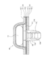
この第2実施形態のワイヤハーネス1Aは、不図示の被取付体上の直線状の配索経路に敷設される電線束10Aと、この電線束10Aを配索経路に整合する直線状に支持する電線支持部材としてのプラスチック段ボールシート25と、該プラスチック段ボールシート25を前記配索経路に固定する固定手段としてのクランプ30と、を備える。
The wire harness 1A according to the second embodiment supports a
電線束10Aは、フラットケーブルではなく、独立した複数本の電線11の束である。
The
この第2実施形態の場合、電線支持部材としてのプラスチック段ボールシート25は、中空部25aの延在方向が、配索経路の延在方向に一致するように裁断されている。また、プラスチック段ボールシート25は、図5に示すように、複数の中空部25aが一列に並んだ構造である。
In the case of the second embodiment, the plastic
この第2実施形態の場合、電線束10Aを構成する複数の電線11を、図4に示すように、プラスチック段ボールシート25の中空部25aに挿通させることで、電線束10Aを配索経路に整合する直線状に支持した状態とする。
In the case of this second embodiment, as shown in FIG. 4, the plurality of
第2実施形態におけるクランプ30は、第1実施形態と同一のもので、プラスチック段ボールシート25の一面(裏面)に埋設状態に固定される基端部と、該基端部から延出して前記配索経路上の取付穴に挿入されると該取付穴に係合する係止爪と、を備えたものである。
The
この第2実施形態のワイヤハーネス1Aの場合、電線支持部材は、1枚のプラスチック段ボールシート25だけで済み、第1実施形態の場合と比較すると、第2のプラスチック段ボールシート22が不要になる分、更に軽量化することができる。また、プラスチック段ボールシート相互の溶着作業も不要になる。また、電線束10Aを構成する電線11が、プラスチック段ボールシート25の中空部25aに収容されるため、配索経路に位置する外部機材が直接電線11に触れることが無くなり、電線11に対する保護性能を向上させることができる。
In the case of the wire harness 1A of the second embodiment, the electric wire supporting member is only one plastic
また、電線束10Aを構成する電線11がプラスチック段ボールシート25内に収容されるため、ワイヤハーネス1の横断面形状を、単純な平板状にすることができ、狭い配索スペースに対しても、配索を容易にすることができる。
Moreover, since the
なお、本発明は、上述した実施形態に限定されるものではなく、適宜、変形、改良、等が可能である。その他、上述した実施形態における各構成要素の材質、形状、寸法、数、配置箇所、等は本発明を達成できるものであれば任意であり、限定されない。 In addition, this invention is not limited to embodiment mentioned above, A deformation | transformation, improvement, etc. are possible suitably. In addition, the material, shape, dimensions, number, arrangement location, and the like of each component in the above-described embodiment are arbitrary and are not limited as long as the present invention can be achieved.
例えば、電線支持部材として使用するプラスチック段ボールシートは、複数の中空部が上下2段に並ぶ構造のもの、中空部の形状が三角形状のものなども使用可能である。 For example, the plastic corrugated cardboard sheet used as the electric wire support member may have a structure in which a plurality of hollow parts are arranged in two upper and lower stages, or a hollow part having a triangular shape.
また、電線支持部材を被取付体に固定する固定手段は、上記実施形態に示したクランプに限らない。固定手段は、例えば、両面粘着テープ等を使用することも可能である。 Moreover, the fixing means for fixing the electric wire support member to the attached body is not limited to the clamp shown in the above embodiment. As the fixing means, for example, a double-sided adhesive tape or the like can be used.
ここで、上述した本発明に係るワイヤハーネスの実施形態の特徴をそれぞれ以下[1]〜[4]に簡潔に纏めて列記する。 Here, the features of the embodiment of the wire harness according to the present invention described above are briefly summarized and listed in the following [1] to [4], respectively.
[1] 被取付体上の直線状の配索経路に敷設される電線束(10)と、この電線束(10)を前記配索経路に整合する直線状に支持する電線支持部材(20)と、を備え、
前記電線支持部材(20)に、中空部の延在方向が前記配索経路の延在方向に一致するように裁断されたプラスチック段ボールシート(21)を使用したこと、
を特徴とするワイヤハーネス(1)。
[1] A wire bundle (10) laid on a straight wiring path on the body to be attached, and a wire support member (20) for supporting the wire bundle (10) in a straight line matching the wiring path. And comprising
For the electric wire support member (20), using a plastic corrugated cardboard sheet (21) cut so that the extending direction of the hollow portion coincides with the extending direction of the routing path,
A wire harness (1) characterized by the above.
[2] 上記[1]に記載のワイヤハーネス(1)において、
前記電線支持部材(20)は、
前記中空部の延在方向が前記配索経路の延在方向に一致するように裁断されて、その一方の面の上に前記電線束(10)が載置される第1のプラスチック段ボールシート(21)と、
該第1のプラスチック段ボールシート(21)上の前記電線束(10)の上を横断すると共に前記電線束(10)の両側にはみ出した両端部(22a)が前記第1のプラスチック段ボールシート(21)の表面に面接触可能な寸法に裁断された第2のプラスチック段ボールシート(22)と、を備え、
前記第1のプラスチック段ボールシート(21)との間に前記電線束(10)を挟んだ状態に前記第1のプラスチック段ボールシート(21)の上に配置した前記第2のプラスチック段ボールシート(22)の前記両端部(22a)を前記第1のプラスチック段ボールシート(21)に溶着させることで、前記第1のプラスチック段ボールシート(21)上に載置された前記電線束(10)を前記第1のプラスチック段ボールシート(21)に固定することを特徴とするワイヤハーネス(1)。
[2] In the wire harness (1) according to the above [1],
The wire support member (20)
A first plastic corrugated sheet (sheet) in which the extending direction of the hollow portion is cut so as to coincide with the extending direction of the routing path, and the wire bundle (10) is placed on one surface thereof 21) and
Both ends (22a) which cross over the wire bundle (10) on the first plastic corrugated sheet (21) and protrude on both sides of the wire bundle (10) are the first plastic corrugated sheet (21). 2) a second plastic corrugated sheet (22) cut to a size capable of surface contact with the surface of
The second plastic cardboard sheet (22) disposed on the first plastic cardboard sheet (21) with the wire bundle (10) sandwiched between the first plastic cardboard sheet (21). By welding the both ends (22a) of the first plastic corrugated sheet (21) to the first plastic corrugated sheet (21), the wire bundle (10) placed on the first plastic corrugated sheet (21) is A wire harness (1) characterized by being fixed to a plastic corrugated cardboard sheet (21).
[3] 上記[1]に記載のワイヤハーネスにおいて、
前記電線支持部材(20)は、中空部(25a)の延在方向が前記配索経路の延在方向に一致するように裁断されたプラスチック段ボールシート(25)であって、
前記電線束(10)を構成する複数の電線(11)を、前記中空部(25a)に挿通させることで、前記電線束(10)を前記配索経路に整合する直線状に支持した状態とすることを特徴とするワイヤハーネス(1A)。
[3] In the wire harness described in [1] above,
The wire support member (20) is a plastic corrugated sheet (25) cut so that the extending direction of the hollow portion (25a) coincides with the extending direction of the routing path,
A state in which the plurality of electric wires (11) constituting the electric wire bundle (10) are inserted into the hollow portion (25a), thereby supporting the electric wire bundle (10) in a straight line shape that matches the routing route; A wire harness (1A) characterized by:
[4] 上記[1]〜[3]の何れかに記載のワイヤハーネスにおいて、
前記電線支持部材を前記配索経路に固定する固定手段(30)をさらに備え、
前記固定手段(30)は、被取付体上の配索経路に載置される前記プラスチック段ボールシート(21,25)の一面に埋設状態に固定される基端部と、該基端部から延出して前記配索経路上の取付穴に挿入されると該取付穴に係合する係止爪と、を備えたクランプであることを特徴とするワイヤハーネス(1)。
[4] In the wire harness according to any one of [1] to [3],
A fixing means (30) for fixing the wire support member to the routing path;
The fixing means (30) includes a base end portion fixed in an embedded state on one surface of the plastic corrugated sheet (21, 25) placed on the routing path on the mounted body, and extends from the base end portion. A wire harness (1), characterized in that the wire harness (1) is a clamp provided with a locking claw that engages with the mounting hole when it is taken out and inserted into the mounting hole on the routing path.
1,1A ワイヤハーネス
10,10A 電線束
11 電線
20 電線支持部材
21 第1のプラスチック段ボールシート(電線支持部材)
22 第2のプラスチック段ボールシート(電線支持部材)
22a 端部
25 プラスチック段ボールシート(電線支持部材)
25a 中空部
30 クランプ(固定手段)
1,
22 Second plastic corrugated sheet (wire support member)
Claims (5)
前記電線支持部材は、
中空部の延在方向が前記配索経路の延在方向に一致するように裁断されて、その一方の面の上に前記電線束が載置される第1のプラスチック段ボールシートと、
該第1のプラスチック段ボールシート上の前記電線束の上を横断すると共に前記電線束の両側にはみ出した両端部が前記第1のプラスチック段ボールシートの表面に面接触可能な寸法に裁断された第2のプラスチック段ボールシートと、を備え、
前記第1のプラスチック段ボールシートとの間に前記電線束を挟んだ状態に前記第1のプラスチック段ボールシートの上に配置した前記第2のプラスチック段ボールシートの前記両端部を前記第1のプラスチック段ボールシートの表面に面接触するように固定することで、前記第1のプラスチック段ボールシート上に載置された前記電線束を前記第1のプラスチック段ボールシートに固定することを特徴とするワイヤハーネス。 An electric wire bundle laid in a linear wiring path on the mounted body, and an electric wire support member for supporting the electric wire bundle in a straight line matching the wiring path,
The wire support member is
A first plastic corrugated sheet in which the extending direction of the hollow portion is cut so as to coincide with the extending direction of the wiring path, and the wire bundle is placed on one surface thereof;
A second cross section that crosses over the wire bundle on the first plastic corrugated sheet and that has both ends protruding to both sides of the wire bundle is cut to a size that allows surface contact with the surface of the first plastic corrugated sheet. A plastic corrugated sheet, and
The both ends of the second plastic corrugated sheet placed on the first plastic corrugated sheet with the wire bundle sandwiched between the first plastic corrugated sheet and the first plastic corrugated sheet. A wire harness characterized in that the wire bundle placed on the first plastic corrugated sheet is fixed to the first plastic corrugated sheet by being fixed so as to be in surface contact with the surface of the wire.
前記電線支持部材は、
中空部の延在方向が前記配索経路の延在方向に一致するように裁断されて、その一方の面の上に前記電線束が載置される第1のプラスチック段ボールシートと、
該第1のプラスチック段ボールシート上の前記電線束の上を横断すると共に前記電線束の両側にはみ出した両端部が前記第1のプラスチック段ボールシートの表面に面接触可能な寸法に裁断された第2のプラスチック段ボールシートと、を備え、
前記第1のプラスチック段ボールシートとの間に前記電線束を挟んだ状態に前記第1のプラスチック段ボールシートの上に配置した前記第2のプラスチック段ボールシートの前記両端部を前記第1のプラスチック段ボールシートに溶着させることで、前記第1のプラスチック段ボールシート上に載置された前記電線束を前記第1のプラスチック段ボールシートに固定することを特徴とするワイヤハーネス。 An electric wire bundle laid in a linear wiring path on the mounted body, and an electric wire support member for supporting the electric wire bundle in a straight line matching the wiring path,
The wire support member is
Is cut to the extending direction of the middle hollow portion coincides with the extending direction of the wiring path, a first plastic cardboard sheet in which the wire bundle is placed on the one surface,
A second cross section that crosses over the wire bundle on the first plastic corrugated sheet and that has both ends protruding to both sides of the wire bundle is cut to a size that allows surface contact with the surface of the first plastic corrugated sheet. A plastic corrugated sheet, and
The both ends of the second plastic corrugated sheet placed on the first plastic corrugated sheet with the wire bundle sandwiched between the first plastic corrugated sheet and the first plastic corrugated sheet. A wire harness characterized in that the wire bundle placed on the first plastic corrugated sheet is fixed to the first plastic corrugated sheet by being welded to the first plastic corrugated sheet.
前記電線支持部材を前記配索経路に固定する固定手段をさらに備え、
前記固定手段は、被取付体上の配索経路に載置される前記第1のプラスチック段ボールシートの一面に埋設状態に固定される基端部と、該基端部から延出して前記配索経路上の取付穴に挿入されると該取付穴に係合する係止爪と、を備えたクランプであることを特徴とするワイヤハーネス。 In the wire harness according to claim 1 or claim 2 ,
A fixing means for fixing the wire support member to the routing path;
Said fixing means includes a base end portion fixed to an embedded state on one side of the first plastic cardboard sheet placed on the routing path on the mounting member, said extending from the base end wiring A wire harness comprising: a clamp provided with a locking claw that engages with the mounting hole when inserted into the mounting hole on the path.
前記配索経路に固定する固定手段としてのクランプを前記裁断前または前記裁断後に取付け、A clamp as a fixing means for fixing to the routing path is attached before or after the cutting,
前記電線支持部材の一方の面の上に電線束を載置し、A wire bundle is placed on one surface of the wire support member,
前記電線束を前記配索経路に整合する直線状に前記電線支持部材に支持したことを特徴とするワイヤハーネスの製造方法。A method of manufacturing a wire harness, characterized in that the wire bundle is supported by the wire support member in a straight line matching the wiring path.
前記もう1つのプラスチック段ボールシートの両端部は、それぞれ溶着させることで、前記電線支持部材に固定することを特徴とする請求項4に記載のワイヤハーネスの製造方法。The method of manufacturing a wire harness according to claim 4, wherein both ends of the other plastic corrugated cardboard sheet are fixed to the electric wire support member by welding.
Priority Applications (1)
| Application Number | Priority Date | Filing Date | Title |
|---|---|---|---|
| JP2012270405A JP6059975B2 (en) | 2012-12-11 | 2012-12-11 | Wire harness and method of manufacturing wire harness |
Applications Claiming Priority (1)
| Application Number | Priority Date | Filing Date | Title |
|---|---|---|---|
| JP2012270405A JP6059975B2 (en) | 2012-12-11 | 2012-12-11 | Wire harness and method of manufacturing wire harness |
Publications (3)
| Publication Number | Publication Date |
|---|---|
| JP2014117099A JP2014117099A (en) | 2014-06-26 |
| JP2014117099A5 JP2014117099A5 (en) | 2015-11-12 |
| JP6059975B2 true JP6059975B2 (en) | 2017-01-11 |
Family
ID=51172573
Family Applications (1)
| Application Number | Title | Priority Date | Filing Date |
|---|---|---|---|
| JP2012270405A Active JP6059975B2 (en) | 2012-12-11 | 2012-12-11 | Wire harness and method of manufacturing wire harness |
Country Status (1)
| Country | Link |
|---|---|
| JP (1) | JP6059975B2 (en) |
Families Citing this family (12)
| Publication number | Priority date | Publication date | Assignee | Title |
|---|---|---|---|---|
| JP6156118B2 (en) * | 2013-08-02 | 2017-07-05 | 株式会社オートネットワーク技術研究所 | Wire harness with protector, manufacturing method of wire harness with protector, protector assembly jig |
| JP6156269B2 (en) * | 2014-06-30 | 2017-07-05 | 株式会社オートネットワーク技術研究所 | Housing case for electric vehicle parts and electric wire module |
| JP2016039689A (en) * | 2014-08-07 | 2016-03-22 | 株式会社オートネットワーク技術研究所 | Protector and wire module |
| JP2016134953A (en) * | 2015-01-16 | 2016-07-25 | 住友電装株式会社 | Protector for wiring harness |
| JP2016134982A (en) * | 2015-01-19 | 2016-07-25 | 住友電装株式会社 | Identification structure for wiring harness |
| JP2016152749A (en) * | 2015-02-19 | 2016-08-22 | 住友電装株式会社 | Wiring harness |
| JP6323399B2 (en) * | 2015-06-18 | 2018-05-16 | 株式会社オートネットワーク技術研究所 | Electric wire module and electric wire protection member |
| JP6562760B2 (en) * | 2015-08-07 | 2019-08-21 | 矢崎総業株式会社 | Wire harness |
| JP6562759B2 (en) * | 2015-08-07 | 2019-08-21 | 矢崎総業株式会社 | Wire harness |
| JP2017135874A (en) * | 2016-01-28 | 2017-08-03 | 株式会社オートネットワーク技術研究所 | Wire with protection part |
| JP6508074B2 (en) | 2016-01-28 | 2019-05-08 | 株式会社オートネットワーク技術研究所 | Arrangement structure of wire with protector and wire with protector |
| US20230138937A1 (en) * | 2020-02-27 | 2023-05-04 | Furukawa Electric Co., Ltd. | Wire harness exterior body, and wire harness with exterior body |
Family Cites Families (2)
| Publication number | Priority date | Publication date | Assignee | Title |
|---|---|---|---|---|
| JPH0330207Y2 (en) * | 1985-04-30 | 1991-06-26 | ||
| JPH10252947A (en) * | 1997-03-07 | 1998-09-22 | Yasushi Ishikawa | Panel-like cord holder |
-
2012
- 2012-12-11 JP JP2012270405A patent/JP6059975B2/en active Active
Also Published As
| Publication number | Publication date |
|---|---|
| JP2014117099A (en) | 2014-06-26 |
Similar Documents
| Publication | Publication Date | Title |
|---|---|---|
| JP6059975B2 (en) | Wire harness and method of manufacturing wire harness | |
| JP5894386B2 (en) | Wire harness with clamp | |
| JP6201975B2 (en) | Wire Harness | |
| EP3219554B1 (en) | Method for assembling wire harness, interference suppressing member, and wire harness assembly structure | |
| JP2014117099A5 (en) | ||
| JP6224945B2 (en) | Wire harness | |
| JP2013016367A (en) | Connector support tool, wiring tool, and wiring harness | |
| US10214160B2 (en) | Wire module and wire protection member | |
| JP2014052028A (en) | Arrangement tool | |
| JP2016134958A (en) | Support structure for wiring harness | |
| WO2013001665A1 (en) | Wiring tool and wire harness | |
| WO2020059694A1 (en) | Wiring member | |
| JP2007112181A (en) | Flat harness assembly for vehicle seat and flat harness wiring method | |
| JP5919661B2 (en) | Wiring tool, wire harness, and method of manufacturing wire harness | |
| WO2017073449A1 (en) | Wire harness and method for manufacturing same | |
| JP2016165166A (en) | Arrangement structure for wire with protective member, and wire with protective member | |
| JP2000067659A (en) | Flat harness | |
| WO2014175047A1 (en) | Wire-harness attachment method | |
| JP2016146707A (en) | Wire harness support, wire harness, and protection member | |
| JP2006025506A (en) | Method of attaching wire harness, and attachment structure | |
| JP2017050980A (en) | Exterior member, wire with exterior member, and manufacturing method of wire with exterior member | |
| JP5739856B2 (en) | Interior material module | |
| JP2011229351A (en) | In-vehicle wire harness | |
| JP4797011B2 (en) | Flat wire routing jig structure, flat wire routing method, and flat wire assembly | |
| JP2020073373A (en) | Assembling structure of wiring member |
Legal Events
| Date | Code | Title | Description |
|---|---|---|---|
| RD02 | Notification of acceptance of power of attorney |
Free format text: JAPANESE INTERMEDIATE CODE: A7422 Effective date: 20150122 |
|
| A521 | Request for written amendment filed |
Free format text: JAPANESE INTERMEDIATE CODE: A523 Effective date: 20150928 |
|
| A621 | Written request for application examination |
Free format text: JAPANESE INTERMEDIATE CODE: A621 Effective date: 20151119 |
|
| A977 | Report on retrieval |
Free format text: JAPANESE INTERMEDIATE CODE: A971007 Effective date: 20160810 |
|
| A131 | Notification of reasons for refusal |
Free format text: JAPANESE INTERMEDIATE CODE: A131 Effective date: 20160830 |
|
| A521 | Request for written amendment filed |
Free format text: JAPANESE INTERMEDIATE CODE: A523 Effective date: 20161025 |
|
| TRDD | Decision of grant or rejection written | ||
| A01 | Written decision to grant a patent or to grant a registration (utility model) |
Free format text: JAPANESE INTERMEDIATE CODE: A01 Effective date: 20161115 |
|
| A61 | First payment of annual fees (during grant procedure) |
Free format text: JAPANESE INTERMEDIATE CODE: A61 Effective date: 20161212 |
|
| R150 | Certificate of patent or registration of utility model |
Ref document number: 6059975 Country of ref document: JP Free format text: JAPANESE INTERMEDIATE CODE: R150 |
|
| R250 | Receipt of annual fees |
Free format text: JAPANESE INTERMEDIATE CODE: R250 |
|
| R250 | Receipt of annual fees |
Free format text: JAPANESE INTERMEDIATE CODE: R250 |
|
| R250 | Receipt of annual fees |
Free format text: JAPANESE INTERMEDIATE CODE: R250 |
|
| R250 | Receipt of annual fees |
Free format text: JAPANESE INTERMEDIATE CODE: R250 |
|
| S531 | Written request for registration of change of domicile |
Free format text: JAPANESE INTERMEDIATE CODE: R313531 |
|
| R350 | Written notification of registration of transfer |
Free format text: JAPANESE INTERMEDIATE CODE: R350 |
|
| R250 | Receipt of annual fees |
Free format text: JAPANESE INTERMEDIATE CODE: R250 |