JP6059346B2 - Vibration damping device for car body - Google Patents
Vibration damping device for car body Download PDFInfo
- Publication number
- JP6059346B2 JP6059346B2 JP2015526445A JP2015526445A JP6059346B2 JP 6059346 B2 JP6059346 B2 JP 6059346B2 JP 2015526445 A JP2015526445 A JP 2015526445A JP 2015526445 A JP2015526445 A JP 2015526445A JP 6059346 B2 JP6059346 B2 JP 6059346B2
- Authority
- JP
- Japan
- Prior art keywords
- hydraulic
- vehicle body
- attenuator
- damping device
- vibration damping
- Prior art date
- Legal status (The legal status is an assumption and is not a legal conclusion. Google has not performed a legal analysis and makes no representation as to the accuracy of the status listed.)
- Active
Links
- 238000013016 damping Methods 0.000 title claims description 167
- 239000003921 oil Substances 0.000 claims description 49
- 239000010720 hydraulic oil Substances 0.000 claims description 38
- 238000005192 partition Methods 0.000 claims description 6
- 230000008878 coupling Effects 0.000 claims description 3
- 238000010168 coupling process Methods 0.000 claims description 3
- 238000005859 coupling reaction Methods 0.000 claims description 3
- 239000000725 suspension Substances 0.000 description 25
- 230000002093 peripheral effect Effects 0.000 description 14
- 230000002238 attenuated effect Effects 0.000 description 7
- 230000006835 compression Effects 0.000 description 7
- 238000007906 compression Methods 0.000 description 7
- 230000000694 effects Effects 0.000 description 6
- 239000012530 fluid Substances 0.000 description 5
- 230000008859 change Effects 0.000 description 4
- 125000006850 spacer group Chemical group 0.000 description 4
- 238000006073 displacement reaction Methods 0.000 description 3
- 230000004043 responsiveness Effects 0.000 description 3
- 230000005540 biological transmission Effects 0.000 description 2
- 230000005489 elastic deformation Effects 0.000 description 2
- 239000002184 metal Substances 0.000 description 2
- 238000000034 method Methods 0.000 description 2
- 229910000831 Steel Inorganic materials 0.000 description 1
- 239000006096 absorbing agent Substances 0.000 description 1
- 239000000428 dust Substances 0.000 description 1
- 230000007246 mechanism Effects 0.000 description 1
- 230000000644 propagated effect Effects 0.000 description 1
- 238000007789 sealing Methods 0.000 description 1
- 230000035939 shock Effects 0.000 description 1
- 239000010959 steel Substances 0.000 description 1
- 230000007704 transition Effects 0.000 description 1
- XLYOFNOQVPJJNP-UHFFFAOYSA-N water Substances O XLYOFNOQVPJJNP-UHFFFAOYSA-N 0.000 description 1
Images


Classifications
-
- B—PERFORMING OPERATIONS; TRANSPORTING
- B62—LAND VEHICLES FOR TRAVELLING OTHERWISE THAN ON RAILS
- B62D—MOTOR VEHICLES; TRAILERS
- B62D24/00—Connections between vehicle body and vehicle frame
- B62D24/04—Vehicle body mounted on resilient suspension for movement relative to the vehicle frame
-
- F—MECHANICAL ENGINEERING; LIGHTING; HEATING; WEAPONS; BLASTING
- F16—ENGINEERING ELEMENTS AND UNITS; GENERAL MEASURES FOR PRODUCING AND MAINTAINING EFFECTIVE FUNCTIONING OF MACHINES OR INSTALLATIONS; THERMAL INSULATION IN GENERAL
- F16F—SPRINGS; SHOCK-ABSORBERS; MEANS FOR DAMPING VIBRATION
- F16F13/00—Units comprising springs of the non-fluid type as well as vibration-dampers, shock-absorbers, or fluid springs
- F16F13/005—Units comprising springs of the non-fluid type as well as vibration-dampers, shock-absorbers, or fluid springs comprising both a wound spring and a damper, e.g. a friction damper
- F16F13/007—Units comprising springs of the non-fluid type as well as vibration-dampers, shock-absorbers, or fluid springs comprising both a wound spring and a damper, e.g. a friction damper the damper being a fluid damper
-
- F—MECHANICAL ENGINEERING; LIGHTING; HEATING; WEAPONS; BLASTING
- F16—ENGINEERING ELEMENTS AND UNITS; GENERAL MEASURES FOR PRODUCING AND MAINTAINING EFFECTIVE FUNCTIONING OF MACHINES OR INSTALLATIONS; THERMAL INSULATION IN GENERAL
- F16F—SPRINGS; SHOCK-ABSORBERS; MEANS FOR DAMPING VIBRATION
- F16F9/00—Springs, vibration-dampers, shock-absorbers, or similarly-constructed movement-dampers using a fluid or the equivalent as damping medium
- F16F9/10—Springs, vibration-dampers, shock-absorbers, or similarly-constructed movement-dampers using a fluid or the equivalent as damping medium using liquid only; using a fluid of which the nature is immaterial
- F16F9/14—Devices with one or more members, e.g. pistons, vanes, moving to and fro in chambers and using throttling effect
- F16F9/16—Devices with one or more members, e.g. pistons, vanes, moving to and fro in chambers and using throttling effect involving only straight-line movement of the effective parts
- F16F9/22—Devices with one or more members, e.g. pistons, vanes, moving to and fro in chambers and using throttling effect involving only straight-line movement of the effective parts with one or more cylinders each having a single working space closed by a piston or plunger
- F16F9/26—Devices with one or more members, e.g. pistons, vanes, moving to and fro in chambers and using throttling effect involving only straight-line movement of the effective parts with one or more cylinders each having a single working space closed by a piston or plunger with two cylinders in line and with the two pistons or plungers connected together
-
- F—MECHANICAL ENGINEERING; LIGHTING; HEATING; WEAPONS; BLASTING
- F16—ENGINEERING ELEMENTS AND UNITS; GENERAL MEASURES FOR PRODUCING AND MAINTAINING EFFECTIVE FUNCTIONING OF MACHINES OR INSTALLATIONS; THERMAL INSULATION IN GENERAL
- F16F—SPRINGS; SHOCK-ABSORBERS; MEANS FOR DAMPING VIBRATION
- F16F9/00—Springs, vibration-dampers, shock-absorbers, or similarly-constructed movement-dampers using a fluid or the equivalent as damping medium
- F16F9/06—Springs, vibration-dampers, shock-absorbers, or similarly-constructed movement-dampers using a fluid or the equivalent as damping medium using both gas and liquid
-
- F—MECHANICAL ENGINEERING; LIGHTING; HEATING; WEAPONS; BLASTING
- F16—ENGINEERING ELEMENTS AND UNITS; GENERAL MEASURES FOR PRODUCING AND MAINTAINING EFFECTIVE FUNCTIONING OF MACHINES OR INSTALLATIONS; THERMAL INSULATION IN GENERAL
- F16F—SPRINGS; SHOCK-ABSORBERS; MEANS FOR DAMPING VIBRATION
- F16F9/00—Springs, vibration-dampers, shock-absorbers, or similarly-constructed movement-dampers using a fluid or the equivalent as damping medium
- F16F9/10—Springs, vibration-dampers, shock-absorbers, or similarly-constructed movement-dampers using a fluid or the equivalent as damping medium using liquid only; using a fluid of which the nature is immaterial
- F16F9/14—Devices with one or more members, e.g. pistons, vanes, moving to and fro in chambers and using throttling effect
- F16F9/16—Devices with one or more members, e.g. pistons, vanes, moving to and fro in chambers and using throttling effect involving only straight-line movement of the effective parts
-
- F—MECHANICAL ENGINEERING; LIGHTING; HEATING; WEAPONS; BLASTING
- F16—ENGINEERING ELEMENTS AND UNITS; GENERAL MEASURES FOR PRODUCING AND MAINTAINING EFFECTIVE FUNCTIONING OF MACHINES OR INSTALLATIONS; THERMAL INSULATION IN GENERAL
- F16F—SPRINGS; SHOCK-ABSORBERS; MEANS FOR DAMPING VIBRATION
- F16F9/00—Springs, vibration-dampers, shock-absorbers, or similarly-constructed movement-dampers using a fluid or the equivalent as damping medium
- F16F9/32—Details
- F16F9/56—Means for adjusting the length of, or for locking, the spring or damper, e.g. at the end of the stroke
Landscapes
- Engineering & Computer Science (AREA)
- General Engineering & Computer Science (AREA)
- Mechanical Engineering (AREA)
- Chemical & Material Sciences (AREA)
- Combustion & Propulsion (AREA)
- Transportation (AREA)
- Fluid-Damping Devices (AREA)
- Vehicle Body Suspensions (AREA)
- Vibration Prevention Devices (AREA)
- Body Structure For Vehicles (AREA)
Description
本発明は、車体の振動を減衰させて乗り心地を向上させる車体用振動減衰装置に関するものである。 The present invention relates to a vibration damping device for a vehicle body that attenuates vibrations of the vehicle body to improve riding comfort.
車両の車体は、走行時に外力が加えられることにより僅かながらも弾性変形し、この弾性変形が原因で数十マイクロメートルから1〜2ミリメートル程度の微細な振動を発生することが知られている。この弾性変形をもたらす外力は、路面の凹凸を乗り越えた車輪や、エンジンなどから車体に加えられる。
従来、この種の車体の振動を減衰させるために、車体に振動減衰装置を取付けることがある。従来の車体用振動減衰装置としては、例えば特許文献1に記載された油圧式のものがある。It is known that a vehicle body is elastically deformed slightly when an external force is applied during traveling, and fine vibrations of about several tens of micrometers to 1 to 2 millimeters are generated due to the elastic deformation. The external force that causes this elastic deformation is applied to the vehicle body from a wheel or engine that has overcome the unevenness of the road surface.
Conventionally, in order to attenuate the vibration of this type of vehicle body, a vibration damping device may be attached to the vehicle body. As a conventional vehicle body vibration damping device, for example, there is a hydraulic type device described in
特許文献1に開示された油圧式の車体用振動減衰装置は、減衰力発生用の油圧シリンダ部と、この油圧シリンダ部から突出するピストンロッドに結合された連結ロッド部とによって構成されている。油圧シリンダ部は、油圧シリンダと、この油圧シリンダの中に移動自在に嵌合されたピストンおよびフリーピストンと、このピストンに接続されたピストンロッドとを備えている。
The hydraulic vehicle body vibration damping device disclosed in
ピストンは、油圧シリンダ内の作動油室を2つの油室に分けている。このピストンには、2つの油室を互い連通する作動油通路と、この作動油通路を開閉する減衰力発生用の逆止弁とが設けられている。ピストンロッドは、一方の油室を貫通して油圧シリンダの外に突出している。
フリーピストンは、油圧シリンダ内を高圧ガスが充填されたガス室と作動油室とに仕切っている。The piston divides the hydraulic oil chamber in the hydraulic cylinder into two oil chambers. The piston is provided with a hydraulic oil passage that communicates the two oil chambers with each other and a check valve for generating a damping force that opens and closes the hydraulic oil passage. The piston rod penetrates one oil chamber and protrudes out of the hydraulic cylinder.
The free piston partitions the inside of the hydraulic cylinder into a gas chamber filled with high-pressure gas and a hydraulic oil chamber.
この油圧シリンダ部は、それ自体が車体の左右方向または前後方向の一端部に直接固定されている。一方、ピストンは、ピストンロッドと連結ロッドとを介して車体の左右方向または前後方向の他端部に固定されている。
この従来の車体用振動減衰装置においては、車体の振動でピストンと油圧シリンダとが相対移動し、作動油がピストンの逆止弁を通過することによって減衰力が生じる。The hydraulic cylinder portion itself is directly fixed to one end portion in the left-right direction or the front-rear direction of the vehicle body. On the other hand, the piston is fixed to the other end in the left-right direction or the front-rear direction of the vehicle body via a piston rod and a connecting rod.
In this conventional vehicle body vibration damping device, the piston and the hydraulic cylinder move relative to each other due to the vibration of the vehicle body, and the hydraulic oil passes through the check valve of the piston to generate a damping force.
乗用車やその他の自動車などの乗員が運転して走行する車両は、乗り心地のさらなる改善を求められるものである。しかし、特許文献1に開示された従来の車体用振動減衰装置では、車両の乗り心地を向上させるにも限界があった。この理由は、後述するように二つある。
Vehicles driven by passengers such as passenger cars and other automobiles are required to further improve the ride comfort. However, the conventional vehicle body vibration damping device disclosed in
第1の理由は、上述のように油圧シリンダが車体の左右方向または前後方向の一端部に直接固定されていることから、油圧シリンダに伝達される振動の伝達経路の長さと、ピストンに伝達される振動の伝達経路の長さとが異なるからである。すなわち、油圧シリンダ部で発生する減衰力は、油圧シリンダ側の車体には直接作用する。これに対して、ピストン側の車体には、ピストンロッドと連結ロッドとからなる長い非剛体物を介して減衰力が作用する。この非剛体物とは、ばね成分を有し、弾性変形するものをいう。すなわち、ピストン側の車体には、この非剛体物が途中に介在することにより減衰力が減らされて作用する。このため、車体の一端部と他端部とで振動減衰の効果が異なるから、車両の乗り心地を更に向上させることは難しい。 The first reason is that, as described above, the hydraulic cylinder is directly fixed to one end of the vehicle body in the left-right direction or the front-rear direction, so that the length of the transmission path of vibration transmitted to the hydraulic cylinder and the piston are transmitted to the piston. This is because the length of the vibration transmission path is different. That is, the damping force generated in the hydraulic cylinder part directly acts on the vehicle body on the hydraulic cylinder side. On the other hand, a damping force acts on the piston-side vehicle body via a long non-rigid body composed of a piston rod and a connecting rod. This non-rigid object has a spring component and is elastically deformed. That is, the non-rigid body is interposed in the middle of the piston-side vehicle body so that the damping force is reduced. For this reason, it is difficult to further improve the riding comfort of the vehicle because the vibration damping effect differs between the one end and the other end of the vehicle body.
第2の理由は、ピストンの移動速度が著しく遅く、逆止弁が開かない場合に、逆止弁の着座部やピストンの摺動部等の所謂リーク部を作動油が流れるからである。作動油は粘性抵抗を有するものである。すなわち、この場合は、リーク部を通過する作動油の粘性抵抗に起因して、ピストンの移動速度の割に大きな減衰力が生じる。この結果、ピストンと油圧シリンダの相対移動が阻害されてしまうから、振動が減衰されず車両の乗り心地が低下することになる。ピストンの移動速度が著しく遅い場合とは、例えば、ピストンの作動初期や、乗員が感じることができないほど小さく車体が緩やかに振動したときなどである。 The second reason is that when the moving speed of the piston is extremely slow and the check valve does not open, the hydraulic oil flows through a so-called leak part such as a seating part of the check valve or a sliding part of the piston. The hydraulic oil has viscous resistance. That is, in this case, a large damping force is generated for the moving speed of the piston due to the viscous resistance of the hydraulic oil passing through the leak portion. As a result, since the relative movement between the piston and the hydraulic cylinder is hindered, the vibration is not attenuated and the riding comfort of the vehicle is lowered. The case where the moving speed of the piston is remarkably slow is, for example, the initial operation of the piston or the case where the vehicle body gently vibrates so as not to be felt by the occupant.
本発明はこのような問題を解消するためになされたもので、車両の乗り心地を更に向上できる車体用振動減衰装置を提供することを目的とする。 The present invention has been made to solve such a problem, and an object thereof is to provide a vehicle body vibration damping device that can further improve the riding comfort of a vehicle.
この目的を達成するために、本発明に係る車体用振動減衰装置は、車体の予め定めた左右方向の一端部に位置する第1の取付位置に一端部が取付けられる第1の油圧式減衰器と、前記第1の油圧式減衰器の他端部に連結部材を介して連結され、この連結部材とは反対側の端部が車体の予め定めた左右方向の他端部に位置する第2の取付位置に取付けられる第2の油圧式減衰器とを備え、前記第1の油圧式減衰器と前記第2の油圧式減衰器は、作動油が充填された油室を有する油圧シリンダと、前記油圧シリンダの中に移動自在に嵌合し、前記油室を第1の油室と第2の油室とに仕切るピストンと、前記ピストンに接続され、前記油圧シリンダの一端部から突出するピストンロッドと、前記油圧シリンダの中に移動自在に嵌合し、油圧シリンダ内を高圧ガスが充填されたガス室と前記油室とに仕切って前記油室内の作動油を加圧するフリーピストンと、前記ピストンの両面の受圧面積の差に起因してピストンロッドに作用する軸方向の力を打ち消し、前記軸方向の力をバランスさせるばね部材と、前記第1の油室と前記第2の油室とを連通する作動油通路と、前記作動油通路に設けられた絞りとを含み、前記第1の油圧式減衰器と、前記第2の油圧式減衰器と、前記連結部材とは、長手方向に並ぶ状態で連結され、前記第1の油圧式減衰器の油圧シリンダとピストンロッドとのうちいずれか一方の部材が前記連結部材に連結されるとともに、他方の部材が前記第1の取付位置に取付けられ、前記第2の油圧式減衰器の油圧シリンダとピストンロッドとのうちいずれか一方の部材が前記連結部材に連結されるとともに、他方の部材が前記第2の取付位置に取付けられ、前記第1の取付位置は、前記車体の前後方向の一端部に位置付けられ、前記第2の取付位置は、前記車体の前後方向の他端部に位置付けられているものである。 In order to achieve this object, a vehicle body vibration damping device according to the present invention includes a first hydraulic attenuator having one end mounted at a first mounting position positioned at a predetermined left and right end of the vehicle body. And a second end of the first hydraulic attenuator that is connected to the other end of the first hydraulic attenuator via a connecting member, and an end opposite to the connecting member is located at a predetermined other end in the left-right direction of the vehicle body. A second hydraulic attenuator attached to the attachment position, the first hydraulic attenuator and the second hydraulic attenuator having a hydraulic cylinder filled with hydraulic oil, A piston that movably fits in the hydraulic cylinder and partitions the oil chamber into a first oil chamber and a second oil chamber, and a piston that is connected to the piston and protrudes from one end of the hydraulic cylinder A rod is movably fitted in the hydraulic cylinder, and the hydraulic cylinder A free piston that pressurizes the hydraulic oil in the oil chamber by dividing the gas chamber into a gas chamber filled with high-pressure gas and the oil chamber, and an axial direction that acts on the piston rod due to a difference in pressure receiving areas on both surfaces of the piston A spring member that balances the axial force, a hydraulic oil passage that communicates the first oil chamber and the second oil chamber, and a throttle provided in the hydraulic oil passage. The first hydraulic attenuator, the second hydraulic attenuator, and the connecting member are connected in a state of being aligned in the longitudinal direction, and a hydraulic cylinder and a piston of the first hydraulic attenuator One of the members is connected to the connecting member, and the other member is attached to the first attachment position, and the hydraulic cylinder and the piston rod of the second hydraulic attenuator Either one of the members is While being connected to the binding member, attached the other member to the second mounting position, said first mounting position is positioned at one end of the longitudinal direction of the vehicle body, said second attachment position, It is positioned at the other end portion in the front-rear direction of the vehicle body .
本発明に係る第1の油圧式減衰器と第2の油圧式減衰器は、それぞれピストンと油圧シリンダとが相対移動したときに減衰力が発生するものである。第1の油圧式減衰器で発生した減衰力は、油圧シリンダとピストンロッドとのうちいずれか一方の部材から車体の第1の取付位置に直接作用する。第2の油圧式減衰器で発生した減衰力は、油圧シリンダとピストンロッドとのうちいずれか一方の部材から車体の第2の取付位置に直接作用する。
このため、車体の振動が車体の第1の取付部と第2の取付部とにおいて均等に減衰される。The first hydraulic attenuator and the second hydraulic attenuator according to the present invention generate a damping force when the piston and the hydraulic cylinder move relative to each other, respectively. The damping force generated by the first hydraulic attenuator acts directly on the first mounting position of the vehicle body from either one of the hydraulic cylinder and the piston rod. The damping force generated by the second hydraulic attenuator acts directly on the second mounting position of the vehicle body from either one of the hydraulic cylinder and the piston rod.
For this reason, the vibration of the vehicle body is evenly damped in the first mounting portion and the second mounting portion of the vehicle body.
油圧式減衰器内に充填されている作動油は、粘性を有するものである。また、油圧シリンダとピストンを有する油圧式減衰器は、作動初期などの油圧シリンダに対するピストンの移動速度が低い場合に、逆止弁の着座部やピストンの摺動部等の所謂リーク部から若干作動油が漏洩することが知られている。この作動油の漏洩時には、作動油の粘性抵抗の大きさに基づく大きさでピストンの移動速度が低い割りに大きな減衰力が生じる。この減衰力の大きさは、油圧シリンダに対するピストンの移動距離が相対的に短くなることにより小さくなる。 The hydraulic oil filled in the hydraulic damper is viscous. In addition, a hydraulic attenuator having a hydraulic cylinder and a piston operates slightly from a so-called leak part such as a seating part of a check valve or a sliding part of the piston when the moving speed of the piston with respect to the hydraulic cylinder is low at the initial stage of operation. It is known that oil leaks. When the hydraulic oil leaks, a large damping force is generated for a low movement speed of the piston with a magnitude based on the magnitude of the viscous resistance of the hydraulic oil. The magnitude of the damping force is reduced as the moving distance of the piston relative to the hydraulic cylinder becomes relatively shorter.
本発明の車体用振動減衰装置において、油圧式減衰器毎の油圧シリンダに対するピストンの移動量は、連結部材が剛体である場合には車体用振動減衰装置の両端間の変位量の1/2になる。なお、従来の車体用振動減衰装置のように油圧式減衰器を1個のみ使用する従来の車体用振動減衰装置において、油圧シリンダに対するピストンの移動量は、車体用振動減衰装置の両端間の変位量と一致する。 In the vehicle body vibration damping device of the present invention, the movement amount of the piston with respect to the hydraulic cylinder for each hydraulic attenuator is ½ of the displacement amount between both ends of the vehicle body vibration damping device when the connecting member is a rigid body. Become. In the conventional vehicle vibration damping device that uses only one hydraulic attenuator as in the conventional vehicle vibration damping device, the amount of movement of the piston relative to the hydraulic cylinder is the displacement between both ends of the vehicle vibration damping device. Match the quantity.
このため、本発明によれば、油圧式減衰器を1個のみ使用する従来の車体用振動減衰装置と比べて、油圧シリンダに対するピストンの移動速度が低いときに漏洩する作動油の量が減少し、作動油の粘性抵抗に基づいて生じる減衰力が小さくなる。この結果、作動初期に車体の振動が緩やかに減衰される。 Therefore, according to the present invention, the amount of hydraulic fluid that leaks when the moving speed of the piston relative to the hydraulic cylinder is low is reduced as compared with the conventional vibration damping device for a vehicle body that uses only one hydraulic attenuator. The damping force generated based on the viscous resistance of the hydraulic oil is reduced. As a result, the vibration of the vehicle body is gently attenuated at the beginning of operation.
さらに、第1の油圧式減衰器および第2の油圧式減衰器は、作動油の粘性抵抗を利用してエネルギーを消費する、いわゆる粘性ダンパとしても機能するものである。このため、本発明に係る車体用振動減衰装置は、振動が伝播される方向に依存することなく、高周波域の振動であっても減衰させることができる。この車体用振動減衰装置は、複数の油圧式減衰器を備えているから、油圧式減衰器を一つのみ備える従来の車体用振動減衰装置と比べると、高周波域の振動を減衰させる性能が高いものとなり、しかも高周波域の振動をバランスよく減衰させるものとなる。
したがって、本発明によれば、車両の乗り心地を更に向上可能な車体用振動減衰装置を提供することができる。Furthermore, the first hydraulic attenuator and the second hydraulic attenuator function as so-called viscous dampers that consume energy by utilizing the viscous resistance of the hydraulic oil. For this reason, the vehicle body vibration damping device according to the present invention can attenuate even high-frequency vibrations without depending on the direction in which the vibrations are propagated. Since this vehicle vibration attenuator has a plurality of hydraulic attenuators, it has a higher performance for attenuating vibrations in the high frequency range than a conventional vehicle attenuator having only one hydraulic attenuator. In addition, the vibration in the high frequency range is attenuated in a well-balanced manner.
Therefore, according to the present invention, it is possible to provide a vehicle body vibration damping device that can further improve the riding comfort of the vehicle.
(第1の参考例)
先ず、本発明に係る車体用振動減衰装置の参考となる技術を図1〜図5によって詳細に説明する。
図1に示す車両1は、乗員(図示せず)が運転して走行するもので、例えば乗用車である。この車両1の車体2には、左右一対の前輪3と、左右一対の後輪4とが設けられている。
この種の車体2は、例えば高張力鋼板などによるモノコックボディなどで構成されており、走行時に外力が加えられることにより弾性変形し、例えば左右方向や前後方向などに振動するものである。この振動を発生させる外力としては、走行時に前輪3と後輪4が凹凸を乗り越えることにより車体2に加えられる力や、振動するエンジン(図示せず)から受ける力などがある。また、この種の車両1においては、車室(図示せず)のドアを閉めたときにも車体2が振動することがある。このような車体2の振動は、乗員に不快感を与えることがある。
(First reference example )
First, a technique that serves as a reference for a vehicle body vibration damping device according to the present invention will be described in detail with reference to FIGS .
A
This type of
また、この種の車両1の車室には、オーディオ(図示せず)が設けられることがある。このオーディオの音の周波数は、走行時の車体振動の周波数(40Hz程度)と比べて高い高周波成分(500Hz程度)も多く含まれている。車体は、このオーディオの音にも共振することがあり、このような場合には、オーディオ効果にも影響を及ぼすことがある。
In addition, an audio (not shown) may be provided in the passenger compartment of this type of
この参考例による車両1は、このような車体2の不必要な振動を減衰させるために、車体2の前部に第1の車体用振動減衰装置11が設けられているとともに、車体2の後部に第2の車体用振動減衰装置12が設けられている。第1の車体用振動減衰装置11と第2の車体用振動減衰装置12は、同一のものを用いることができる。
第1の車体用振動減衰装置11および第2の車体用振動減衰装置12の一端部は、車体2の予め定めた第1の取付位置P1に取付けられ、他端部は、予め定めた第2の取付位置P2に取付けられている。なお、第1の取付位置P1と第2の取付位置P2とに高低差があったとしても、同等の効果が得られる。
The
One end portions of the first vehicle body
これらの第1の取付位置P1と第2の取付位置P2としては、図1に示すように、前輪用懸架装置の一部である左右一対のサスペンションタワー13,14の上端部とすることができる。すなわち、この参考例による第1の車体用振動減衰装置11と第2の車体用振動減衰装置12の一端部(車体左側の端部)は、車体左側に位置するサスペンションタワー13に取付けられ、他端部は、車体右側に位置するサスペンションタワー14に取付けられている。なお、図1に示すサスペンションタワー13,14は、実際の位置とは異なり、前輪3や後輪4の後方に描かれている。
As these 1st attachment positions P1 and 2nd attachment positions P2, as shown in FIG. 1, it can be made into the upper end part of a pair of left and right suspension towers 13 and 14 which are a part of the suspension apparatus for front wheels. . That is, one end portion (the left end portion of the vehicle body) of the first vehicle body
第1の車体用振動減衰装置11と第2の車体用振動減衰装置12は、長手方向の両側に位置する第1の油圧式減衰器15および第2の油圧式減衰器16と、これらの第1の油圧式減衰器15と第2の油圧式減衰器16との間に位置する連結ロッド17とを備えている。これらの第1の油圧式減衰器15と、第2の油圧式減衰器16と、連結ロッド17とは、詳細は後述するが、長手方向に並ぶ状態で連結されている。この参考例による第1の車体用振動減衰装置11と第2の車体用振動減衰装置12とにおいては、これらの部材が同一軸線上に並べられている。この参考例においては、連結ロッド17が本発明でいう「連結部材」に相当する。
The first vehicle body
第1の油圧式減衰器15と第2の油圧式減衰器16とは、同一のものである。これらの第1の油圧式減衰器15および第2の油圧式減衰器16は、図2Aおよび図2Bに示すように、サスペンションタワー13,14に取付けられる一端部が後述する油圧シリンダ18によって構成されている。すなわち、第1の油圧式減衰器15の油圧シリンダ18が第1の取付位置P1(車体左側のサスペンションタワー13)に取付けられている。また、第2の油圧式減衰器16の油圧シリンダ18が第2の取付位置P2(車体右側のサスペンションタワー14)に取付けられている。
The first
第1の油圧式減衰器15の他端部と第2の油圧式減衰器16の他端部は、後述するピストンロッド19によって形成されている。第1の油圧式減衰器15のピストンロッド19は、連結ロッド17を介して第2の油圧式減衰器16のピストンロッド19に連結されている。すなわち、第1の油圧式減衰器15のピストンロッド19と第2の油圧式減衰器16のピストンロッド19とが連結ロッド17を介して互いに連結されている。
The other end of the first
第1の油圧式減衰器15と第2の油圧式減衰器16の油圧シリンダ18は、それぞれ作動油が充填された油室21を有するもので、図3に示すように、円筒からなるシリンダチューブ22と、このシリンダチューブ22に取付けられた第1の蓋部材23と第2の蓋部材24とを備えている。第1の蓋部材23は、シリンダチューブ22の一端(図3においては左端)を閉塞している。
The
第1の蓋部材23は、シリンダチューブ22内に嵌合された状態でシリンダチューブ22に溶接されている。この第1の蓋部材23には、断面U字状に形成された取付部材25が溶接されている。この取付部材25は、サスペンションタワー13,14の上端部に設けられた取付用ブラケット26(図2A参照)に図示していない固定用ボルトによって固定される。すなわち、この参考例による油圧シリンダ18は、取付部材25と取付用ブラケット26とを介してサスペンションタワー13,14に取付けられている。この取付用ブラケット26は、車体2の振動が油圧シリンダ18側に伝達される剛性をもって形成されている。本発明に係る車体用振動減衰装置は、このように第1の取付位置P1および第2の取付位置P2との間に振動伝達が可能な剛性構造体が介在するものも含む。
The
第2の蓋部材24は、シリンダチューブ22の他端を閉塞するとともに、後述するピストンロッド19を移動自在に支持している。この第2の蓋部材24の両端部には、ピストンロッド19が貫通する部分をシールするためのシール部材29が設けられている。このシール部材29は、油室21側に位置する第1のシール部材29aおよび第2のシール部材29bと、油室21の外に位置する第3のシール部材29cとから構成されている。この第2の蓋部材24は、シリンダチューブ22内に嵌合され、第1のスプリングシート30とともにシリンダチューブ22にサークリップ27,28によって固定されている。
The
シリンダチューブ22内には、ピストン31とフリーピストン32とがそれぞれ移動自在に嵌合されている。ピストン31は、シリンダチューブ22内に嵌合する断面円形に形成されており、油圧シリンダ18内の油室21を第1の油室33と第2の油室34とに仕切っている。このピストン31の外周部には、シリンダチューブ22の内周面との間をシールするシール部材35が設けられている。また、シール部材35の内周側にはOリング35aが配置されている。Oリング35aは、シール部材35を径方向外方に拡径されるように付勢すると共に、シール部材35の内周面とピストン31の外周部との間の隙間をシールしている。ピストン31の軸心部には、ピストンロッド19の基端部が貫通している。このピストン31は、ピストンロッド19の先端部に後述するピストンバルブ36の弁体37,38や第2のスプリングシート31a、ワッシャ31bとともに固定用ナット39によって固定されている。
In the
第1の油室33は、ピストン31と後述するフリーピストン32との間に形成されている。第2の油室34は、ピストン31と第2の蓋部材24との間に形成されている。
フリーピストン32は、シリンダチューブ22内における第1の蓋部材23が位置する一端側に配置され、油圧シリンダ18内を油室21とガス室40とに仕切っている。フリーピストン32の外周部にはOリング32aが嵌合されている。このOリング32aは、ガス室40と油室21との間をシールしている。ガス室40には、高圧のN2 ガスが充填されている。このため、油室21内の作動油は、フリーピストン32によって加圧されている。The
The
ピストン31と第2の蓋部材24との間には圧縮コイルばね41が圧縮された状態で挿入されている。圧縮コイルばね41における第2の蓋部材24側の一端部は、第1のスプリングシート30に当接し、他端部は、第2のスプリングシート31aに当接している。ピストンロッド19は、この圧縮コイルばね41の中心部を貫通している。ピストン31は、圧縮コイルばね41のばね力によって油圧式減衰器15,16の収縮される方向(図3においては左方)に付勢されている。
A
圧縮コイルばね41は、ピストン31の両面の受圧面積の差に起因してピストンロッド19に作用する軸方向の力を打ち消すためのものである。この軸方向の力は、ピストン31の第1の油室33側の受圧面積より第2の油室34側の受圧面積の方が小さいことにより生じ、ピストンロッド19を油圧式減衰器15,16が伸びる方向に押す。この参考例においては、圧縮コイルばね41によって、本発明でいう「ばね部材」が構成されている。
The
この参考例による第1の油圧式減衰器15と第2の油圧式減衰器16の自由長は、上述した軸方向の力が圧縮コイルばね41のばね力によって打ち消されてバランスした状態の長さである。第1の油圧式減衰器15と第2の油圧式減衰器16は、この自由長が車体2への取付寸法と一致するようにN2 ガスの圧力が調整される。
このように自由長が車体2への取付寸法と一致することにより、第1の車体用振動減衰装置11や第2の車体用振動減衰装置12を車体2に取付ける作業が容易になる。また、第1の車体用振動減衰装置11や第2の車体用振動減衰装置12が車体2に取付けられた状態で初期荷重が0となる。このため、第1の油圧式減衰器15と第2の油圧式減衰器16が応答性よく収縮し、減衰力を発生させることができる。
The free lengths of the first
Since the free length matches the mounting dimension to the
ピストン31に設けられたピストンバルブ36は、車両1の懸架装置用ショックアブソーバなどに使用されているものと同等の構造のものである。このピストンバルブ36は、図4に示すように、第1の絞り42と第2の絞り43とによって構成されている。第1の絞り42は、ピストン31を貫通する第1の作動油通路44に設けられている。第2の絞り43は、ピストン31を貫通する第2の作動油通路45に設けられている。
The
第1の作動油通路44における第2の油室34側の端部は、環状の凹陥部44aによって形成されている。
第1の絞り42は、この凹陥部44aを閉じる逆止弁を構成するもので、複数の円板状の弁体37を備えている。これらの弁体37は、凹陥部44aの外周縁に自らのばね力で押し付けられる状態でピストンロッド19に装着されている。すなわち、この弁体37の内周部は、ピストンロッド19に嵌合し、ナット39を締め上げた状態で、ピストンロッド19に設けられた第1のスペーサ46によってピストン31側に押圧される。The end of the first
The
第1のスペーサ46は、第2のスプリングシート31aとともにピストン31から離間する方向への移動が規制される状態でピストンロッド19に装着されている。このように弁体37の内周部がピストン31側に押圧されることにより、弁体37が変形し、所定の初期荷重で凹陥部44aの外周縁に押し付けられる。
この結果、第1の絞り42の弁体37は、第1の作動油通路44における第2の油室34側の開口部に所定の初期荷重で押付けられ、この開口部を閉塞する。このため、この弁体37は、第1の油室33の油圧が弁体27の初期荷重より高まったときに開く。The
As a result, the
第2の作動油通路45における第1の油室33側の端部は、環状の凹陥部45aによって形成されている。第2の絞り43は、この凹陥部45aを閉じる逆止弁を構成するもので、複数の円板状の弁体38を備えている。これらの弁体38は、凹陥部45aの外周縁に自らのばね力で押し付けられる状態でピストンロッド19に装着されている。すなわち、この弁体38の内周部は、ピストンロッド19に嵌合し、ナット39を締め上げた状態で、ピストンロッド19に設けられた第2のスペーサ47によってピストン31側に押圧される。
An end of the second
第2のスペーサ47は、ワッシャ31bとともにピストン31から離間する方向への移動が規制される状態でピストンロッド19に装着されている。このように弁体38の内周部がピストン31側に押圧されることにより、弁体38が変形し、所定の初期荷重で凹陥部45aの外周縁に押し付けられる。
この結果、第2の絞り43の弁体38は、第2の作動油通路45における第1の油室33側の開口部に所定の初期荷重で押付けられ、この開口部を閉塞する。このため、この弁体38は、第2の油室34の油圧が弁体38の初期荷重より高まったときに開く。The
As a result, the
第1の絞り42の弁体37と第2の絞り43の弁体38の厚みおよび枚数は、第1の油圧式減衰器15と第2の油圧式減衰器16とにおいて発生させる減衰力の大きさに基づいて決められている。これらの弁体37,38のばね力が大きくなると、発生する減衰力が増大する。この参考例による第1の車体用振動減衰装置11と第2の車体用振動減衰装置12の減衰力の大きさは、油圧式減衰器を1個のみ用いる場合の減衰力の大きさと同等である。
The thickness and the number of
ピストンロッド19の先端部は、図3に示すように、第2の蓋部材24を貫通してシリンダチューブ22の外に突出し、連結ロッド17の端部にねじによって結合されている。連結ロッド17は、金属製の丸棒によって形成されている。この連結ロッド17の両端部には、第1の油圧式減衰器15と第2の油室式減衰器16とを取付けるための雌ねじ17aが形成されている。
As shown in FIG. 3, the tip of the
ピストンロッド19と連結ロッド17との結合部分は、ピストンロッド19に形成された雄ねじ19aを連結ロッド17の雌ねじ17aに螺着させ、ロックナット48によって締付ける構造が採られている。このねじによる連結ロッド17の取付構造を採ることによって、N2 ガス圧のばらつきに起因して変化する第1の車体用振動減衰装置11と第2の車体用振動減衰装置12の自由長を微調整することができる。連結ロッド17の長手方向の中央部には、図2Aおよび図2Bに示すように、丸棒からなる連結ロッド17に工具(図示せず)を掛けるための平坦面49が形成されている。この平坦面49は、連結ロッド17の外周部の2箇所に互いに平行に形成されている。上述したロックナット48を締め付ける作業は、この平坦面49に工具を係合させて連結ロッド17の回転を規制した状態で行われる。The connecting portion between the
ピストンロッド19と連結ロッド17との結合部分は、図3に示すように、連結ロッド17とシリンダチューブ22とを接続するゴムブーツ50によって覆われている。このゴムブーツ50は、ピストンロッド19に泥水や塵埃が付着することを防ぐためのもので、円錐筒状に形成されている。このゴムブーツ50の一端部は、シリンダチューブ22の外周面に固着され、他端部は、連結ロッド17の外周面に固着されている。
As shown in FIG. 3, the coupling portion between the
ここで、第1の車体用振動減衰装置11と第2の車体用振動減衰装置12を車体2に取付けるときの手順の一例を説明する。この取付けを行うにあたっては、先ず、第1の車体用振動減衰装置11と第2の車体用振動減衰装置12を仮組みの状態にする。この仮組みの状態とは、例えば、第1の油圧式減衰器15のピストンロッド19に連結ロッド17の一端部が結合され、かつこの連結ロッド17の他端部に第2の油圧式減衰器のピストンロッド19が仮にねじ込まれている状態である。第1の油圧式減衰器15のピストンロッド19と連結ロッド17とは、この仮組みの状態でロックナット48を締め込むことにより結合される。ロックナット40を締め込むにあたっては、連結ロッド17の平坦面49に工具を係合させて連結ロッド17の回転を規制した状態で行う。
Here, an example of a procedure for attaching the first vehicle body
次に、上述した第1の油圧式減衰器15に設けられている取付部材25を、サスペンションタワー13の取付用ブラケット26に図示していない固定用ボルトによって仮に取付ける。そして、連結ロッド17の他端部と第2の油圧式減衰器16のピストンロッド19とのねじ込み量を調整し、第2の油圧式減衰器16の取付部材25を他方のサスペンションタワー14の取付用ブラケット26に固定用ボルトによって仮に取付ける。
Next, the mounting
すなわち、第1の車体用振動減衰装置11と第2の車体用振動減衰装置12の全長が左右一対のサスペンションタワー13,14の間隔に合わせて調整される。そして、第1の車体用振動減衰装置11と第2の車体用振動減衰装置12が車体2に保持されている状態で、第2の油圧式減衰器16のロックナット48を締め付ける。このロックナット48を締め込む作業は、連結ロッド17の平坦面49に工具を係合させて連結ロッド17の回転を規制しながら行う。このロックナット48が締め込まれることによって、第2の油圧式減衰器16のピストンロッド19が連結ロッド17に結合される。
しかる後、第1の油圧式減衰器15と第2の油圧式減衰器16の取付部材25をそれぞれ取付用ブラケット26に固定用ボルトにより本固定することよって、第1の車体用振動減衰装置11と第2の車体用振動減衰装置12の車体2への取付け作業が終了する。That is, the total length of the first vehicle body
Thereafter, the first
このように構成された第1の車体用振動減衰装置11と第2の車体用振動減衰装置12は、それぞれ両端部に第1の油圧式減衰器15と第2の油圧式減衰器16とを備えている。これらの第1の油圧式減衰器15と第2の油圧式減衰器15は、それぞれ油圧シリンダ18とピストン31とが相対移動したときに減衰力が発生するものである。第1の油圧式減衰器15で発生した減衰力は、油圧シリンダ18から車体2の第1の取付位置P1に直接作用する。第2の油圧式減衰器16で発生した減衰力は、油圧シリンダ18から車体2の第2の取付位置P2に直接作用する。
このため、車体2の振動が第1の取付位置P1と第2の取付位置P2とにおいて均等に減衰される。The first vehicle body
For this reason, the vibration of the
車体2の振動により左右一対のサスペンションタワー13,14間の間隔が変化する場合は、第1の油圧式減衰器15と第2の油圧式減衰器16とにおいてピストン31がシリンダチューブ22に対して軸線方向(車体2の左右方向)に移動する。第1の油圧式減衰器15と第2の油圧式減衰器16は、作動油が高圧のN2 ガスによって加圧されており、油室21内に臨む弾性変形可能な全てのシール部材29、ピストン31のOリング35、フリーピストン32のOリング32aがそれ以上弾性変形することができないような状態に保たれている。このため、第1の車体用振動減衰装置11と第2の車体用振動減衰装置12においては、作動油が第1の油室33と第2の油室34との間を応答性よく流れるから、ピストン31の移動量が数十ミクロン単位である場合であっても応答性よく減衰力を発生する。When the distance between the pair of left and right suspension towers 13, 14 changes due to the vibration of the
車体2の振動が第1の車体用振動減衰装置11と第2の車体用振動減衰装置12に伝達されてピストン31がシリンダチューブ22に対して移動を開始すると、先ず、作動油が漏洩可能な隙間に流入する。この漏洩可能な隙間とは、第1の油室33と第2の油室34との間で作動油が流れることが可能な隙間をいう。この漏洩可能な隙間を以下においてはリーク部という。この参考例による第1の油圧式減衰器15と第2の油圧式減衰器16のリーク部は、図4中に二点鎖線Aで囲まれた範囲にあるリーク部と、図4中に二点鎖線Bで囲まれた範囲にあるリーク部である。以下においては、二点鎖線Aで示すリーク部を第1のリーク部Aといい、二点鎖線Bで示すリーク部を第2のリーク部Bという。
When the vibration of the
第1のリーク部Aは、ピストン31とシリンダチューブ22との間のクリアランスとなる隙間である。第2のリーク部Bは、第1の絞り42と第2の絞り43の弁体37,38と、ピストン31の凹陥部44a,45aの外周縁との間の隙間である。作動油は、粘性を有している。このため、ピストン31が移動を開始した直後であって、弁体37,38が開く以前は、これらの第1のリーク部Aと第2のリーク部Bを作動油が漏洩することにより、作動油の粘性抵抗の大きさに対応する大きさで減衰力が発生する。
The first leak portion A is a gap serving as a clearance between the
ピストン31の移動開始直後の減衰力の大きさは、図5に示すように、ピストン31の移動速度と略比例して変化する。以下においては、作動油の粘性抵抗に基づく減衰力を単に低速時減衰力という。図5においては、この参考例による車体用振動減衰装置の減衰力の変化を実線で示し、油圧式減衰器を1個のみ使用した場合の減衰力の変化を破線で示す。また、図5においては、2個の油圧式減衰器を並列の状態で使用した場合の減衰力の変化を二点鎖線で示す。2個の油圧式減衰器を並列の状態で使用するとは、2個の油圧式減衰器をそれぞれ左右のサスペンションタワー13,14間に設けることを意味する。
The magnitude of the damping force immediately after the start of the movement of the
この参考例による第1の油圧式減衰器15と第2の油圧式減衰器16のピストン31の移動量は、第1の車体用振動減衰装置11と第2の車体用振動減衰装置12の両端間の変位量の半分となる。このため、図5に実線で示すように、この参考例による第1の車体用油圧式振動減衰装置11と第2の車体用油圧式振動減衰装置12の低速時減衰力の大きさは、油圧式減衰器を一つのみ使用する従来の装置(図5において破線で示す)と比べると、ピストン31の移動速度が同一であれば1/2となる。このため、この参考例によれば、油圧式減衰器を1個のみ使用する場合と比べて、第1の油圧式減衰器15と第2の油圧式減衰器16のピストン31の移動速度が著しく低いときに第1のリーク部Aと第2のリーク部Bで漏洩する作動油の量が減少し、作動油の粘性抵抗に基づいて生じる減衰力が小さくなる。
この結果、作動初期などで第1の油圧式減衰器15と第2の油圧式減衰器16のピストン31の移動速度が低いときに車体2の振動が緩やかに減衰される。
The movement amounts of the
As a result, the vibration of the
この参考例による第1の車体用振動減衰装置11と第2の車体用振動減衰装置12とにおいて、ピストン31の移動開始後に移動速度が上昇すると、図5に示すように、低速時減衰力が生じるリーク域L1を経た後、第1の絞り42と第2の絞り43の弁体37,38が開き始める変遷域L2を経てからピストンバルブ36で所定の減衰力が生じるバルブ域L3に移行する。
図5から判るように、第1の車体用振動減衰装置11と第2の車体用振動減衰装置12とにおけるバルブ域L3に移行するときのピストン31の移動速度は、油圧式減衰器を1個のみ使用する場合(図5において破線で示す)のピストン31の移動速度と比べて高くなっている。このことは、作動初期の減衰力の上昇が緩和されて乗り心地が改善されたことを意味する。
バルブ域L3に移行した後は、ピストン31の移動速度の上昇する割合に比べて減衰力の大きさが増大する割合が著しく小さくなる。
In the first vehicle body
As can be seen from FIG. 5, the moving speed of the
After shifting to the valve region L3, the rate at which the magnitude of the damping force increases is significantly smaller than the rate at which the moving speed of the
この参考例による第1の油圧式減衰器15と第2の油圧式減衰器16は、第1の油室33と第2の油室34に貯留された作動油の粘性抵抗を利用してエネルギーを消費する、いわゆる粘性ダンパとしても機能するものである。このため、この参考例による第1の車体用振動減衰装置11と第2の車体用振動減衰装置12は、振動の伝播する方向に依存することなく、高周波域の振動であっても減衰させることができる。この第1の車体用振動減衰装置11と第2の車体用振動減衰装置12は、それぞれ第1の油圧式減衰器15と第2の油圧式減衰器16とを備えているから、油圧式減衰器を一つのみ使用する従来の車体用振動減衰装置と比べると、作動油の量が増加する分、高周波域の振動を減衰させる性能が高いものとなる。
したがって、この参考例によれば、車両の乗り心地を更に向上可能な車体用振動減衰装置を提供することができる。
The first
Therefore, according to this reference example , it is possible to provide a vehicle body vibration damping device that can further improve the riding comfort of the vehicle.
この参考例による第1の車体用振動減衰装置11と第2の車体用振動減衰装置12においては、第1の油圧式減衰器15のピストンロッド19と第2の油圧式減衰器16のピストンロッド19とが連結ロッド17を介して互いに連結されている。また、第1の油圧式減衰器15の油圧シリンダ18が第1の取付位置P1に取付けられている。第2の油圧式減衰器16の油圧シリンダ18が第2の取付位置P2に取付けられている。
このため、この参考例による第1の車体用振動減衰装置11と第2の車体用振動減衰装置12は、両端部が相対的に剛性が高い油圧シリンダ18によって形成されているから、車体2に強固に取付けることができる。
In the first vehicle body
For this reason, the first vehicle body
この参考例による第1の油圧式減衰器15と第2の油圧式減衰器16とは、減衰性能が同一のものである。
このため、第1の油圧式減衰器15と第2の油圧式減衰器16の上述した低速時減衰力は、油圧式減衰器を一つのみ使用する従来の車体用振動減衰装置と比べて1/2になる。また、第1の油圧式減衰器15と第2の油圧式減衰器16が粘性ダンパとして機能して高周波域の振動を減衰させる能力は、油圧式減衰器を一つのみ使用する従来の車体用振動減衰装置と比べると2倍となる。しかも、第1の油圧式減衰器15と第2の油圧式減衰器16は、この高周波域の振動をバランスよく減衰させる。
したがって、この参考例によれば、車両の乗り心地がより一層向上する車体用振動減衰装置を提供することができる。
The first
Therefore, the above-described low-speed damping force of the first
Therefore, according to this reference example , it is possible to provide a vehicle body vibration damping device that further improves the riding comfort of the vehicle.
この参考例による第1の取付位置P1は、車体2の左右方向の一端部に位置する車体左側のサスペンションタワー13である。また、第2の取付位置P2は、車体2の左右方向の他端部に位置する車体右側のサスペンションタワー14である。
このため、この参考例によれば、懸架装置の一部となることから剛性が高くなる左右一対サスペンションタワー13,14に車体用振動減衰装置が取付けられるから、車体2の左右方向の振動が確実に減衰されて乗り心地が向上する。また、この参考例においては、第1の油圧式減衰器15と第2の油圧式減衰器16とが車体2の左右方向に対称となる位置に配置されているから、上述した高周波域の振動の減衰量が車体左側と車体右側とで等しくなる。
The first mounting position P <b> 1 according to this reference example is the
For this reason, according to this reference example , the vibration damping device for the vehicle body is attached to the pair of left and right suspension towers 13 and 14 which are part of the suspension device and have high rigidity. Attenuated to improve ride comfort. In this reference example , the first
この参考例による第1の車体用振動減衰装置11と第2の車体用振動減衰装置12は、それぞれ左右一対のサスペンションタワー13,14間に架け渡されている。しかし、本発明は、このような限定にとらわれることはない。本発明に係る車体用振動減衰装置を取付ける位置としては、車体フレームや、車体下部に位置する懸架装置の取付座や、車体2がモノコックボディである場合はフロアパネルなどが挙げられる。
The first vehicle body
(第2の参考例)
本発明に係る車体用振動減衰装置の第2の参考例を図6A、図6Bおよび図7によって説明する。これらの図において、前記図1〜図5によって説明したものと同一もしくは同等の部材については、同一符号を付し詳細な説明を適宜省略する。
図6Aおよび図6Bに示す車体用振動減衰装置51は、第1の油圧式減衰器15のピストンロッド19と第2の油圧式減衰器16のピストンロッド19とが両端部に位置する状態に組立てられている。
(Second reference example )
A second reference example of the vehicle body vibration damping device according to the present invention will be described with reference to FIGS. 6A, 6B, and 7. FIG . In these drawings, the same or equivalent members as those described with reference to FIGS. 1 to 5 are denoted by the same reference numerals, and detailed description thereof is omitted as appropriate.
6A and 6B is assembled so that the
第1の油圧式減衰器15のピストンロッド19は、取付部材25と取付用ブラケット26とを介して第1の取付位置P1に取付けられている。また、第2の油圧式減衰器16のピストンロッド19は、取付部材25と取付用ブラケット26とを介して第2の取付位置P2に取付けられている。
ピストンロッド19と取付部材25との接続は、図7に示すように、筒体52を介して行われている。この筒体52は、取付部材25に溶接されている。この筒体52の中空部には、雌ねじ52aが形成されている。この雌ねじ52aには、ピストンロッド19に形成されている雄ねじ19aがねじ込まれ、ロックナット53によって固定されている。The
The connection between the
一方、第1の油圧式減衰器15の油圧シリンダ18と、第2の油圧式減衰器16の油圧シリンダ18は、図6Aおよび図6Bに示すように、連結ロッド17を介して互いに連結されている。
油圧シリンダ18と連結ロッド17との接続は、図7に示すように、ねじ軸54を介して行われている。このねじ軸54は、雄ねじからなり、油圧シリンダ18の第1の蓋部材23に一体に形成されている。このねじ軸54は、連結ロッド17の雌ねじ17aにねじ込まれ、ロックナット55によって固定されている。
すなわち、この参考例による第1の油圧式減衰器15と第2の油圧式減衰器16は、両端部にそれぞれねじからなる長さ調整機構56,57が設けられている。このため、この参考例によれば、長さ調節を容易に行うことが可能な車体用振動減衰装置を提供することができる。
On the other hand, the
The
That is, the first
(第3の参考例)
本発明に係る車体用振動減衰装置の第3の参考例を図8Aおよび図8Bによって説明する。図8Aおよび図8Bにおいて、前記図1〜図5によって説明したものと同一もしくは同等の部材については、同一符号を付し詳細な説明を適宜省略する。
図8Aおよび図8Bに示す車体用振動減衰装置61は、車体2に設けられている干渉物62を避けて車体2に取付けることができるものである。車体2の干渉物62を避けるにあたっては、この参考例においては連結ロッド17を途中で曲げて行っている。
(Third reference example )
A third reference example of the vehicle body vibration damping device according to the present invention will be described with reference to FIGS. 8A and 8B . 8A and 8B, members identical or equivalent to those described with reference to FIGS. 1 to 5 are given the same reference numerals, and detailed description thereof is omitted as appropriate.
The vehicle body
すなわち、この参考例による連結ロッド17は、第1の油圧式減衰器15と同一軸線上に位置する第1の直線部63と、第2の油圧式減衰器16と同一軸線上に位置する第2の直線部64と、これらの直線部63,64を接続する屈曲部65とによって構成されている。屈曲部65は、第1の直線部63の軸線C1と第2の直線部64の軸線C2とが、これらの軸線C1,C2とは直交する方向に距離Dだけ離れる形状に形成されている。屈曲部65の形状や位置は、干渉物62の形状、位置などに応じて適宜変更することができる。
この参考例の構成を採ることにより、車体2の干渉物62を避けて車体2に取付けることが可能な車体用振動減衰装置を提供することができる。
In other words, the connecting
By adopting the configuration of this reference example, it is possible to provide a vehicle body vibration damping device that can be attached to the
(第4の参考例)
本発明に係る車体用振動減衰装置の第4の参考例を図9によって説明する。図9に示す車体用振動減衰装置は、車体の前後方向に延びる状態で車体に取付けられている。図9において、前記図1〜図8Aおよび図8Bによって説明したものと同一もしくは同等の部材については、同一符号を付し詳細な説明を適宜省略する。
( Fourth reference example)
A fourth reference example of the vehicle body vibration damping device according to the present invention will be described with reference to FIG. The vehicle body vibration damping device shown in FIG. 9 is attached to the vehicle body so as to extend in the front-rear direction of the vehicle body. 9, the same or equivalent members as described with reference to FIGS. 1 to 8A and 8B are denoted by the same reference numerals, and detailed description thereof is omitted as appropriate.
図9に示す第1の車体用振動減衰装置11と第2の車体用振動減衰装置12は、車体2の前後方向に延びる状態で車体2の底部に取付けられている。この車体2の底部とは、例えば、車体2がフレームを備えている場合は、このフレームの下部であり、車体2がモノコックボディである場合は、下端のフロアパネルなどが挙げられる。また、第1の車体用振動減衰装置11と第2の車体用振動減衰装置12は、前輪側懸架装置の取付座や、後輪側懸架装置の取付座あるいは前後のバンパー取付部近傍を利用して車体2に取付けることも可能である。この第1の車体用振動減衰装置11と第2の車体用振動減衰装置12が取付けられる部位は、車体2の振動を確実に第1の車体用振動減衰装置11と第2の車体用振動減衰装置12とに伝えると共に、第1の車体用振動減衰装置11と第2の車体用振動減衰装置12とにおいて発生した減衰力を確実に車体に伝えるだけの十分な剛性を有する部位であれば、特に限定されることはない。
The first vehicle body
この参考例による第1の車体用振動減衰装置11は、車体2の底部における左右方向の一端側(左端側)に位置付けられ、第2の車体用振動減衰装置12は、車体2の底部における左右方向の他端側に位置付けられている。これらの第1の車体用振動減衰装置11と、第2の車体用振動減衰装置12は、同一のものである。図9に示す第1の取付位置P1は、車体2の前後方向の一端部に位置付けられ、第2の取付位置P2は、車体2の前後方向の他端部に位置付けられている。なお、この形態を採るにあたり、第1の取付位置P1と第2の取付位置P2とに高低差があったとしても、同等の効果が得られる。
The first vehicle body
図9に示す参考例によれば、車体2の前後方向の振動が減衰されて乗り心地が向上する。また、この実施の形態においては、第1の油圧式減衰器15と第2の油圧式減衰器16の減衰性能が同一であるから、高周波域の振動の減衰量が車体前部と車体後部とで等しくなる。
この参考例による車体用振動減衰装置においても、図6A、図6Bおよび図7に示すように、ピストンロッド19が車体2に取付けられる形態や、図8Aおよび図8Bに示すように、第1の油圧式減衰器15と第2の油圧式減衰器16が同一軸線上に位置していない形態を採ることができる。
According to the reference example shown in FIG. 9, the vibration in the front-rear direction of the
Also in the vibration damping device for a vehicle body according to this reference example , as shown in FIGS. 6A, 6B, and 7, the
(発明の実施の形態)
本発明に係る車体用振動減衰装置は、図10に示すように構成することができる。図10に示す車体用振動減衰装置は、斜めに延びる状態で車体2に取付けられている。図10において、前記図1〜図9よって説明したものと同一もしくは同等の部材については、同一符号を付し詳細な説明を適宜省略する。
(Embodiment of the Invention)
The vehicle body vibration damping device according to the present invention can be configured as shown in FIG. The vehicle body vibration damping device shown in FIG. 10 is attached to the
図10に示す第1の車体用振動減衰装置11と第2の車体用振動減衰装置12は、車体2の底部に斜めに傾斜した状態で取付けられている。この実施の形態による第1の車体用振動減衰装置11は、車体前側における車体左側の端部から、車体後側における車体右側の端部に向けて傾斜する状態で車体2に取付けられている。また、第2の車体用振動減衰装置12は、車体前側における車体右側の端部から、車体後側における車体左側の端部に向けて傾斜する状態で車体2に取付けられている。なお、この形態を採るにあたり、第1の取付位置P1と第2の取付位置P2とに高低差があったとしても、同等の効果が得られる。
図10に示す構成を採る場合であっても上述した各参考例の形態を採るときと同等の効果が得られる。
A first vehicle body
Even when the configuration shown in FIG. 10 is adopted, the same effect as that obtained when the above-described embodiments of each reference example are adopted can be obtained.
(第2の実施の形態)
本発明に係る車体用振動減衰装置は、図11〜図13に示すように構成することができる。図11〜図13において、前記図1〜図10によって説明したものと同一もしくは同等の部材については、同一符号を付し詳細な説明を適宜省略する。この実施の形態による車体用振動減衰装置は、請求項5および請求項6記載の発明を構成するものである。
(Second Embodiment)
The vehicle body vibration damping device according to the present invention can be configured as shown in FIGS. 11 to 13, members that are the same as or equivalent to those described with reference to FIGS. The vehicle body vibration damping device according to this embodiment constitutes the inventions of
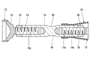
図11に示す車体用振動減衰装置71は、長手方向の両端部に位置する第1の油圧式減衰器15および第2の油圧式減衰器16と、これらの第1の油圧式減衰器15と第2の油圧式減衰器16との間に位置する第3の油圧式減衰器72とを備えている。第3の油圧式減衰器72は、第1の油圧式減衰器15および第2の油圧式減衰器16と同一のものである。すなわち、第1の油圧式減衰器15と、第2の油圧式減衰器16と、第3の油圧式減衰器72とは、減衰性能が同一のものである。
The vehicle body
この実施の形態による第1の油圧式減衰器15と第2の油圧式減衰器16は、油圧シリンダ18が車体用振動減衰装置71の両端側に位置する状態で使用されている。すなわち、取付部材25は、油圧シリンダ18に設けられている。
第1の油圧式減衰器15のピストンロッド19は、連結ロッド73を介して第3の油圧式減衰器72のピストンロッド19に接続されている。第2の油圧式減衰器16のピストンロッド19は、連結ロッド74を介して第3の油圧式減衰器72の油圧シリンダ18に接続されている。この実施の形態においては、第3の油圧式減衰器72と、連結ロッド73,74とによって、本発明でいう「連結部材」が構成されている。The first
The
連結ロッド73と連結ロッド74は、それぞれ金属製の丸棒によって形成されている。また、これらの連結ロッド73,74の長手方向の中央部には、丸棒からなる連結ロッド73,74に工具(図示せず)を掛けるための平坦面49が形成されている。
連結ロッド73の一端部には、図12に示すように、第1の油圧式減衰器15のピストンロッド19とを取付けるための雌ねじ73aが形成されている。連結ロッド73の他端部には、第3の油圧式減衰器72のピストンロッド19を取付けるための雌ねじ73bが形成されている。The connecting
As shown in FIG. 12, an
第1の油圧式減衰器15と第3の油圧式減衰器72のピストンロッド19と連結ロッド73との結合部分は、ピストンロッド19に形成された雄ねじ19aを連結ロッド73の雌ねじ73a,73bに螺着させ、ロックナット48によって締付ける構造が採られている。
連結ロッド74の一端部には、図13に示すように、第2の油圧式減衰器16のピストンロッド19を取付けるための雌ねじ74aが形成されている。連結ロッド74の他端部には、第3の油圧式減衰器72のねじ軸54を取付けるための雌ねじ74bが形成されている。The connecting portion between the
As shown in FIG. 13, an
第2の油圧式減衰器16のピストンロッド19と連結ロッド74との結合部分は、ピストンロッド19に形成された雄ねじ19aを連結ロッド74の雌ねじ74aに螺着させ、ロックナット48によって締付ける構造が採られている。ねじ軸54は、連結ロッド74の雌ねじ74bにねじ込まれ、ロックナット55によって固定されている。
The connecting portion between the
この実施の形態による車体用振動減衰装置71は、上述した実施の形態で示したように車体2に取付けられる。すなわち、この車体用振動減衰装置71は、図1に示したように、車体2の左右方向に延びる状態で車体2に取付けることができる。また、この車体用振動減衰装置71は、図9に示したように、車体2の前後方向に延びる状態や、図10に示したように、車体2に対して斜めに延びる状態で車体1に取付けることができる。
The vehicle body
この実施の形態によれば、第1〜第3の油圧式減衰器15,16,72によって車体2の振動が減衰される。したがって、この実施の形態によれば、第1の油圧式減衰器15と第2の油圧式減衰器16のみを有する第1の車体用振動減衰装置11や第2の車体用振動減衰装置12と比べて、振動を減衰させる能力が高い車体用振動減衰装置を提供することができる。
According to this embodiment, the vibration of the
この実施の形態による第3の油圧式減衰器72は、第1の油圧式減衰器15および第2の油圧式減衰器16と減衰性能が同一のものである。このため、車体2の振動が3箇所で略均等に減衰される。なお、第3の油圧式減衰器72の減衰性能が相対的に低いと、振動がこの第3の油圧式減衰器72だけで減衰されるため、減衰量を十分得ることができない。一方、第3の油圧式減衰器72の減衰性能が相対的に高いと、振動が主に第1、第2の油圧式減衰器15,16で減衰されるようになるから、減衰量がそれほど大きくなることはない。しかし、この実施の形態によれば、3個の油圧式減衰器15,16,72を効率よく使用して大きな減衰量を得ることができる。
The third
1…車両、2…車体、11…第1の車体用振動減衰装置、12…第2の車体用振動減衰装置、13,14…サスペンションタワー、15…第1の油圧式減衰器、16…第2の油圧式減衰器、17…連結ロッド、19…ピストンロッド、22…シリンダチューブ、31…ピストン、32…フリーピストン、33…第1の油室、34…第2の油室、37,38…弁体、40…ガス室、42…第1の絞り、43…第2の絞り、44…第1の作動油通路、45…第2の作動油通路、51,61,71…車体用振動減衰装置、72…第3の油圧式減衰器、P1…第1の取付位置、P2…第2の取付位置。
DESCRIPTION OF
Claims (6)
前記第1の油圧式減衰器の他端部に連結部材を介して連結され、この連結部材とは反対側の端部が車体の予め定めた左右方向の他端部に位置する第2の取付位置に取付けられる第2の油圧式減衰器とを備え、
前記第1の油圧式減衰器と前記第2の油圧式減衰器は、
作動油が充填された油室を有する油圧シリンダと、
前記油圧シリンダの中に移動自在に嵌合し、前記油室を第1の油室と第2の油室とに仕切るピストンと、
前記ピストンに接続され、前記油圧シリンダの一端部から突出するピストンロッドと、
前記油圧シリンダの中に移動自在に嵌合し、油圧シリンダ内を高圧ガスが充填されたガス室と前記油室とに仕切って前記油室内の作動油を加圧するフリーピストンと、
前記ピストンの両面の受圧面積の差に起因してピストンロッドに作用する軸方向の力を打ち消し、前記軸方向の力をバランスさせるばね部材と、
前記第1の油室と前記第2の油室とを連通する作動油通路と、
前記作動油通路に設けられた絞りとを含み、
前記第1の油圧式減衰器と、前記第2の油圧式減衰器と、前記連結部材とは、長手方向に並ぶ状態で連結され、
前記第1の油圧式減衰器の油圧シリンダとピストンロッドとのうちいずれか一方の部材が前記連結部材に連結されるとともに、他方の部材が前記第1の取付位置に取付けられ、
前記第2の油圧式減衰器の油圧シリンダとピストンロッドとのうちいずれか一方の部材が前記連結部材に連結されるとともに、他方の部材が前記第2の取付位置に取付けられ、
前記第1の取付位置は、前記車体の前後方向の一端部に位置付けられ、
前記第2の取付位置は、前記車体の前後方向の他端部に位置付けられている車体用振動減衰装置。 A first hydraulic attenuator having one end attached to a first attachment position located at one end in the left-right direction of the vehicle body,
A second attachment that is connected to the other end of the first hydraulic attenuator via a connecting member, and an end opposite to the connecting member is located at a predetermined other end in the left-right direction of the vehicle body A second hydraulic attenuator mounted in position,
The first hydraulic attenuator and the second hydraulic attenuator are:
A hydraulic cylinder having an oil chamber filled with hydraulic oil;
A piston that movably fits in the hydraulic cylinder and partitions the oil chamber into a first oil chamber and a second oil chamber;
A piston rod connected to the piston and projecting from one end of the hydraulic cylinder;
A free piston that is movably fitted in the hydraulic cylinder, partitions the inside of the hydraulic cylinder into a gas chamber filled with high-pressure gas and the oil chamber, and pressurizes the hydraulic oil in the oil chamber;
A spring member that counteracts the axial force acting on the piston rod due to the difference in pressure receiving area on both sides of the piston, and balances the axial force;
A hydraulic oil passage communicating the first oil chamber and the second oil chamber;
A throttle provided in the hydraulic oil passage,
The first hydraulic attenuator, the second hydraulic attenuator, and the connecting member are connected in a state of being aligned in the longitudinal direction,
One of the members of the hydraulic cylinder and the piston rod of the first hydraulic attenuator is connected to the connecting member, and the other member is attached to the first attachment position,
One of the members of the hydraulic cylinder and the piston rod of the second hydraulic attenuator is connected to the connecting member, and the other member is attached to the second attachment position ,
The first mounting position is positioned at one end of the vehicle body in the front-rear direction,
The vehicle body vibration damping device, wherein the second attachment position is positioned at the other end portion of the vehicle body in the front-rear direction .
前記第1の油圧式減衰器のピストンロッドと第2の油圧式減衰器のピストンロッドとが前記連結部材を介して互いに連結され、
前記第1の油圧式減衰器の油圧シリンダが前記第1の取付位置に取付けられ、
前記第2の油圧式減衰器の油圧シリンダが前記第2の取付位置に取付けられていることを特徴とする車体用振動減衰装置。 The vibration damping device for a vehicle body according to claim 1,
The piston rod of the first hydraulic damper and the piston rod of the second hydraulic damper are connected to each other via the connecting member,
A hydraulic cylinder of the first hydraulic attenuator is mounted at the first mounting position;
A vehicle body vibration damping device, wherein a hydraulic cylinder of the second hydraulic attenuator is mounted at the second mounting position.
前記第1の油圧式減衰器の油圧シリンダと第2の油圧式減衰器の油圧シリンダとが前記連結部材を介して互いに連結され、
前記第1の油圧式減衰器のピストンロッドが前記第1の取付位置に取付けられ、
前記第2の油圧式減衰器のピストンロッドが前記第2の取付位置に取付けられていることを特徴とする車体用振動減衰装置。 The vibration damping device for a vehicle body according to claim 1,
A hydraulic cylinder of the first hydraulic attenuator and a hydraulic cylinder of the second hydraulic attenuator are coupled to each other via the coupling member;
A piston rod of the first hydraulic attenuator is attached to the first attachment position;
A vehicle body vibration damping device, wherein a piston rod of the second hydraulic damper is mounted at the second mounting position.
前記第1の油圧式減衰器と前記第2の油圧式減衰器とは、減衰性能が同一のものであることを特徴とする車体用振動減衰装置。 The vehicle body vibration damping device according to any one of claims 1 to 3,
The vibration damping device for a vehicle body, wherein the first hydraulic attenuator and the second hydraulic attenuator have the same damping performance.
前記連結部材は、前記第1の油圧式減衰器および前記第2の油圧式減衰器と同じ構造の第3の油圧式減衰器を含むことを特徴とする車体用振動減衰装置。 In the vehicle body vibration damping device according to any one of claims 1 to 4 ,
The coupling member includes a third hydraulic attenuator having the same structure as the first hydraulic attenuator and the second hydraulic attenuator.
前記第1の油圧式減衰器と、前記第2の油圧式減衰器と、前記第3の油圧式減衰器とは、減衰性能が同一のものであることを特徴とする車体用振動減衰装置。 The vehicle body vibration damping device according to claim 5 ,
A vibration damping device for a vehicle body, wherein the first hydraulic attenuator, the second hydraulic attenuator, and the third hydraulic attenuator have the same damping performance.
Applications Claiming Priority (3)
| Application Number | Priority Date | Filing Date | Title |
|---|---|---|---|
| JP2013145173 | 2013-07-11 | ||
| JP2013145173 | 2013-07-11 | ||
| PCT/JP2014/068559 WO2015005472A1 (en) | 2013-07-11 | 2014-07-11 | Vibration damping device for vehicle body |
Publications (2)
| Publication Number | Publication Date |
|---|---|
| JP6059346B2 true JP6059346B2 (en) | 2017-01-11 |
| JPWO2015005472A1 JPWO2015005472A1 (en) | 2017-03-02 |
Family
ID=52280149
Family Applications (1)
| Application Number | Title | Priority Date | Filing Date |
|---|---|---|---|
| JP2015526445A Active JP6059346B2 (en) | 2013-07-11 | 2014-07-11 | Vibration damping device for car body |
Country Status (4)
| Country | Link |
|---|---|
| US (1) | US9845113B2 (en) |
| EP (1) | EP3020619A4 (en) |
| JP (1) | JP6059346B2 (en) |
| WO (1) | WO2015005472A1 (en) |
Families Citing this family (6)
| Publication number | Priority date | Publication date | Assignee | Title |
|---|---|---|---|---|
| JP6668859B2 (en) * | 2016-03-18 | 2020-03-18 | アイシン精機株式会社 | Body reinforcement device |
| CN105889404B (en) * | 2016-06-03 | 2017-12-29 | 安徽工程大学 | A kind of detachable energy-absorbing bumper damper |
| JP7000069B2 (en) * | 2017-08-10 | 2022-02-04 | 清水建設株式会社 | Vibration damping device |
| CN108071734B (en) * | 2017-08-24 | 2020-04-07 | 深圳市罗伯医疗科技有限公司 | Damper and walking-aid robot |
| RU195947U1 (en) * | 2017-12-20 | 2020-02-11 | Сергей Николаевич Калинин | TWO-PISTON VEHICLE SHOCK ABSORBER |
| CN111981070B (en) * | 2020-09-01 | 2022-06-24 | 重庆恒伟林汽车零部件有限公司 | Bidirectional automobile damping system |
Citations (2)
| Publication number | Priority date | Publication date | Assignee | Title |
|---|---|---|---|---|
| JP2002533624A (en) * | 1998-12-18 | 2002-10-08 | リチャード・ブガイ | Shock absorber |
| WO2006090586A1 (en) * | 2005-02-24 | 2006-08-31 | Yamaha Hatsudoki Kabushiki Kaisha | Device for reinforcing vehicle body of vehicle |
Family Cites Families (5)
| Publication number | Priority date | Publication date | Assignee | Title |
|---|---|---|---|---|
| JPS6326440A (en) * | 1986-07-21 | 1988-02-04 | Nippon Kokan Kk <Nkk> | Vibration proofing stay for vessel |
| DE4212079C2 (en) * | 1992-04-10 | 2003-04-10 | Stabilus Gmbh | Fluid pressure spring and construction with such a fluid pressure spring |
| IT1271059B (en) * | 1993-11-19 | 1997-05-26 | Stabilus Gmbh | STOP DEVICE TO FIX TWO MOVABLE OBJECTS ONE RELATIVE TO THE OTHER |
| JP4627389B2 (en) | 2000-11-15 | 2011-02-09 | ヤマハ発動機株式会社 | Vehicle reinforcing member and vehicle body structure |
| JP2007203896A (en) * | 2006-02-02 | 2007-08-16 | Yamaha Motor Co Ltd | Reinforcing device for vehicular body |
-
2014
- 2014-07-11 JP JP2015526445A patent/JP6059346B2/en active Active
- 2014-07-11 EP EP14823099.8A patent/EP3020619A4/en not_active Withdrawn
- 2014-07-11 WO PCT/JP2014/068559 patent/WO2015005472A1/en active Application Filing
- 2014-07-11 US US14/903,902 patent/US9845113B2/en active Active
Patent Citations (2)
| Publication number | Priority date | Publication date | Assignee | Title |
|---|---|---|---|---|
| JP2002533624A (en) * | 1998-12-18 | 2002-10-08 | リチャード・ブガイ | Shock absorber |
| WO2006090586A1 (en) * | 2005-02-24 | 2006-08-31 | Yamaha Hatsudoki Kabushiki Kaisha | Device for reinforcing vehicle body of vehicle |
Also Published As
| Publication number | Publication date |
|---|---|
| US20160152276A1 (en) | 2016-06-02 |
| US9845113B2 (en) | 2017-12-19 |
| EP3020619A1 (en) | 2016-05-18 |
| EP3020619A4 (en) | 2016-06-29 |
| JPWO2015005472A1 (en) | 2017-03-02 |
| WO2015005472A1 (en) | 2015-01-15 |
Similar Documents
| Publication | Publication Date | Title |
|---|---|---|
| JP6059346B2 (en) | Vibration damping device for car body | |
| JP5563136B2 (en) | Nested high speed check valve | |
| US9494210B2 (en) | Vehicle mount and method | |
| JP5248852B2 (en) | Vibration damping device for car body | |
| CN105452708A (en) | Shock absorber with frequency dependent passive valve | |
| KR20130020195A (en) | Structure of roll-rod for subframe | |
| JP4970895B2 (en) | Mounting structure of vibration damping device for car body | |
| US20180038442A1 (en) | Vibration damper with a traction stop | |
| JP2010096347A (en) | Hydraulic damper | |
| JP6046106B2 (en) | Shock absorber with two pistons with reduced damping at the beginning of the stroke | |
| JP2008248898A (en) | Cylindrical vibration damper | |
| JP6774794B2 (en) | Strut mounts, strut mount manufacturing methods and automobiles | |
| JP2008002594A (en) | Hydraulic shock absorber, and reinforcing device and vibration damping device using the same | |
| US10295010B2 (en) | Fluid-filled engine mounting apparatus | |
| JP5539629B2 (en) | Piston cylinder assembly | |
| KR102238046B1 (en) | Danymic damper assembly | |
| JP2013170660A (en) | Fluid sealed vibration control device | |
| KR20140062628A (en) | Bush structure | |
| JP2004322945A (en) | Damper for saddle | |
| KR102586913B1 (en) | Shock absorber having structure for absorbing noise and vibration | |
| CN204213245U (en) | A kind of adjustable elastic Vibration absorber of car device | |
| JPH0526570U (en) | Liquid-filled mount | |
| JP2001074086A (en) | Vibration control device | |
| KR20120080870A (en) | Noise decreasing type piston rod of shock absorber for vehicle | |
| KR20030088192A (en) | Strut mounting for a vehicle |
Legal Events
| Date | Code | Title | Description |
|---|---|---|---|
| A02 | Decision of refusal |
Free format text: JAPANESE INTERMEDIATE CODE: A02 Effective date: 20161018 |
|
| A521 | Request for written amendment filed |
Free format text: JAPANESE INTERMEDIATE CODE: A523 Effective date: 20161107 |
|
| A911 | Transfer to examiner for re-examination before appeal (zenchi) |
Free format text: JAPANESE INTERMEDIATE CODE: A911 Effective date: 20161115 |
|
| TRDD | Decision of grant or rejection written | ||
| A01 | Written decision to grant a patent or to grant a registration (utility model) |
Free format text: JAPANESE INTERMEDIATE CODE: A01 Effective date: 20161206 |
|
| A61 | First payment of annual fees (during grant procedure) |
Free format text: JAPANESE INTERMEDIATE CODE: A61 Effective date: 20161208 |
|
| R150 | Certificate of patent or registration of utility model |
Ref document number: 6059346 Country of ref document: JP Free format text: JAPANESE INTERMEDIATE CODE: R150 |
|
| R250 | Receipt of annual fees |
Free format text: JAPANESE INTERMEDIATE CODE: R250 |
|
| R250 | Receipt of annual fees |
Free format text: JAPANESE INTERMEDIATE CODE: R250 |
|
| R250 | Receipt of annual fees |
Free format text: JAPANESE INTERMEDIATE CODE: R250 |
|
| R250 | Receipt of annual fees |
Free format text: JAPANESE INTERMEDIATE CODE: R250 |
|
| R250 | Receipt of annual fees |
Free format text: JAPANESE INTERMEDIATE CODE: R250 |