JP6058635B2 - Cannula for donor organ with or without aortic cuff or patch - Google Patents
Cannula for donor organ with or without aortic cuff or patch Download PDFInfo
- Publication number
- JP6058635B2 JP6058635B2 JP2014508387A JP2014508387A JP6058635B2 JP 6058635 B2 JP6058635 B2 JP 6058635B2 JP 2014508387 A JP2014508387 A JP 2014508387A JP 2014508387 A JP2014508387 A JP 2014508387A JP 6058635 B2 JP6058635 B2 JP 6058635B2
- Authority
- JP
- Japan
- Prior art keywords
- cannula
- circumferential portion
- clamping surface
- vasculature
- seal
- Prior art date
- Legal status (The legal status is an assumption and is not a legal conclusion. Google has not performed a legal analysis and makes no representation as to the accuracy of the status listed.)
- Active
Links
- 210000000056 organ Anatomy 0.000 title description 27
- 210000005166 vasculature Anatomy 0.000 claims description 80
- 239000012530 fluid Substances 0.000 claims description 30
- 230000002792 vascular Effects 0.000 claims description 16
- 230000003287 optical effect Effects 0.000 claims description 10
- 238000004891 communication Methods 0.000 claims description 8
- 239000013536 elastomeric material Substances 0.000 claims description 8
- 230000000295 complement effect Effects 0.000 claims description 4
- 210000001519 tissue Anatomy 0.000 description 17
- 238000000034 method Methods 0.000 description 15
- 230000010412 perfusion Effects 0.000 description 12
- 230000006378 damage Effects 0.000 description 11
- 210000000709 aorta Anatomy 0.000 description 7
- 210000001367 artery Anatomy 0.000 description 5
- 230000003014 reinforcing effect Effects 0.000 description 5
- 241001631457 Cannula Species 0.000 description 4
- 210000003734 kidney Anatomy 0.000 description 4
- 238000004519 manufacturing process Methods 0.000 description 4
- 239000000853 adhesive Substances 0.000 description 3
- 230000001070 adhesive effect Effects 0.000 description 3
- 239000000463 material Substances 0.000 description 3
- 210000002445 nipple Anatomy 0.000 description 3
- 102000001554 Hemoglobins Human genes 0.000 description 2
- 108010054147 Hemoglobins Proteins 0.000 description 2
- QVGXLLKOCUKJST-UHFFFAOYSA-N atomic oxygen Chemical compound [O] QVGXLLKOCUKJST-UHFFFAOYSA-N 0.000 description 2
- 230000000694 effects Effects 0.000 description 2
- 229910052760 oxygen Inorganic materials 0.000 description 2
- 239000001301 oxygen Substances 0.000 description 2
- 238000011179 visual inspection Methods 0.000 description 2
- 208000010496 Heart Arrest Diseases 0.000 description 1
- 208000031481 Pathologic Constriction Diseases 0.000 description 1
- 208000007536 Thrombosis Diseases 0.000 description 1
- 210000003484 anatomy Anatomy 0.000 description 1
- 230000002965 anti-thrombogenic effect Effects 0.000 description 1
- 239000003963 antioxidant agent Substances 0.000 description 1
- 239000010836 blood and blood product Substances 0.000 description 1
- 230000036760 body temperature Effects 0.000 description 1
- 239000003795 chemical substances by application Substances 0.000 description 1
- 238000013461 design Methods 0.000 description 1
- 229920001971 elastomer Polymers 0.000 description 1
- 239000000806 elastomer Substances 0.000 description 1
- 239000000839 emulsion Substances 0.000 description 1
- 210000003743 erythrocyte Anatomy 0.000 description 1
- NBVXSUQYWXRMNV-UHFFFAOYSA-N fluoromethane Chemical compound FC NBVXSUQYWXRMNV-UHFFFAOYSA-N 0.000 description 1
- 208000028867 ischemia Diseases 0.000 description 1
- 230000000302 ischemic effect Effects 0.000 description 1
- 239000007788 liquid Substances 0.000 description 1
- 238000005259 measurement Methods 0.000 description 1
- 238000012986 modification Methods 0.000 description 1
- 230000004048 modification Effects 0.000 description 1
- 238000006213 oxygenation reaction Methods 0.000 description 1
- 238000005502 peroxidation Methods 0.000 description 1
- 238000004321 preservation Methods 0.000 description 1
- 230000037452 priming Effects 0.000 description 1
- 238000005086 pumping Methods 0.000 description 1
- 150000003254 radicals Chemical class 0.000 description 1
- 238000011084 recovery Methods 0.000 description 1
- 210000002254 renal artery Anatomy 0.000 description 1
- 238000007789 sealing Methods 0.000 description 1
- 230000036262 stenosis Effects 0.000 description 1
- 208000037804 stenosis Diseases 0.000 description 1
- 238000002054 transplantation Methods 0.000 description 1
- 210000004026 tunica intima Anatomy 0.000 description 1
- 230000003966 vascular damage Effects 0.000 description 1
- 230000035899 viability Effects 0.000 description 1
- 238000004804 winding Methods 0.000 description 1
Images


Classifications
-
- A—HUMAN NECESSITIES
- A61—MEDICAL OR VETERINARY SCIENCE; HYGIENE
- A61B—DIAGNOSIS; SURGERY; IDENTIFICATION
- A61B17/00—Surgical instruments, devices or methods, e.g. tourniquets
- A61B17/12—Surgical instruments, devices or methods, e.g. tourniquets for ligaturing or otherwise compressing tubular parts of the body, e.g. blood vessels, umbilical cord
- A61B17/122—Clamps or clips, e.g. for the umbilical cord
-
- A—HUMAN NECESSITIES
- A01—AGRICULTURE; FORESTRY; ANIMAL HUSBANDRY; HUNTING; TRAPPING; FISHING
- A01N—PRESERVATION OF BODIES OF HUMANS OR ANIMALS OR PLANTS OR PARTS THEREOF; BIOCIDES, e.g. AS DISINFECTANTS, AS PESTICIDES OR AS HERBICIDES; PEST REPELLANTS OR ATTRACTANTS; PLANT GROWTH REGULATORS
- A01N1/00—Preservation of bodies of humans or animals, or parts thereof
- A01N1/02—Preservation of living parts
- A01N1/0236—Mechanical aspects
- A01N1/0242—Apparatuses, i.e. devices used in the process of preservation of living parts, such as pumps, refrigeration devices or any other devices featuring moving parts and/or temperature controlling components
- A01N1/0247—Apparatuses, i.e. devices used in the process of preservation of living parts, such as pumps, refrigeration devices or any other devices featuring moving parts and/or temperature controlling components for perfusion, i.e. for circulating fluid through organs, blood vessels or other living parts
-
- A—HUMAN NECESSITIES
- A61—MEDICAL OR VETERINARY SCIENCE; HYGIENE
- A61M—DEVICES FOR INTRODUCING MEDIA INTO, OR ONTO, THE BODY; DEVICES FOR TRANSDUCING BODY MEDIA OR FOR TAKING MEDIA FROM THE BODY; DEVICES FOR PRODUCING OR ENDING SLEEP OR STUPOR
- A61M1/00—Suction or pumping devices for medical purposes; Devices for carrying-off, for treatment of, or for carrying-over, body-liquids; Drainage systems
- A61M1/36—Other treatment of blood in a by-pass of the natural circulatory system, e.g. temperature adaptation, irradiation ; Extra-corporeal blood circuits
- A61M1/3621—Extra-corporeal blood circuits
- A61M1/3653—Interfaces between patient blood circulation and extra-corporal blood circuit
- A61M1/3659—Cannulae pertaining to extracorporeal circulation
-
- A—HUMAN NECESSITIES
- A61—MEDICAL OR VETERINARY SCIENCE; HYGIENE
- A61B—DIAGNOSIS; SURGERY; IDENTIFICATION
- A61B17/00—Surgical instruments, devices or methods, e.g. tourniquets
- A61B2017/00831—Material properties
- A61B2017/00902—Material properties transparent or translucent
- A61B2017/00907—Material properties transparent or translucent for light
-
- A—HUMAN NECESSITIES
- A61—MEDICAL OR VETERINARY SCIENCE; HYGIENE
- A61B—DIAGNOSIS; SURGERY; IDENTIFICATION
- A61B17/00—Surgical instruments, devices or methods, e.g. tourniquets
- A61B2017/00969—Surgical instruments, devices or methods, e.g. tourniquets used for transplantation
-
- A—HUMAN NECESSITIES
- A61—MEDICAL OR VETERINARY SCIENCE; HYGIENE
- A61L—METHODS OR APPARATUS FOR STERILISING MATERIALS OR OBJECTS IN GENERAL; DISINFECTION, STERILISATION OR DEODORISATION OF AIR; CHEMICAL ASPECTS OF BANDAGES, DRESSINGS, ABSORBENT PADS OR SURGICAL ARTICLES; MATERIALS FOR BANDAGES, DRESSINGS, ABSORBENT PADS OR SURGICAL ARTICLES
- A61L2300/00—Biologically active materials used in bandages, wound dressings, absorbent pads or medical devices
- A61L2300/40—Biologically active materials used in bandages, wound dressings, absorbent pads or medical devices characterised by a specific therapeutic activity or mode of action
- A61L2300/42—Anti-thrombotic agents, anticoagulants, anti-platelet agents
Landscapes
- Health & Medical Sciences (AREA)
- Life Sciences & Earth Sciences (AREA)
- Engineering & Computer Science (AREA)
- General Health & Medical Sciences (AREA)
- Heart & Thoracic Surgery (AREA)
- Vascular Medicine (AREA)
- Surgery (AREA)
- Veterinary Medicine (AREA)
- Biomedical Technology (AREA)
- Animal Behavior & Ethology (AREA)
- Public Health (AREA)
- Medical Informatics (AREA)
- Molecular Biology (AREA)
- Nuclear Medicine, Radiotherapy & Molecular Imaging (AREA)
- Reproductive Health (AREA)
- Dentistry (AREA)
- Thermal Sciences (AREA)
- Mechanical Engineering (AREA)
- Physics & Mathematics (AREA)
- Wood Science & Technology (AREA)
- Zoology (AREA)
- Environmental Sciences (AREA)
- Cardiology (AREA)
- Anesthesiology (AREA)
- Hematology (AREA)
- Prostheses (AREA)
- Infusion, Injection, And Reservoir Apparatuses (AREA)
- External Artificial Organs (AREA)
- Surgical Instruments (AREA)
Description
関連の技術分野は、カニューレ及びクランプ法、より詳細には、1つ又は複数の臓器を灌流して臓器(単数又は複数)の生存能力を監視、処置、維持、及び/又は回復する、且つ/又は臓器(単数又は複数)を運搬及び/又は保存するためのカニューレ及びクランプ法を含む。 Related technical fields include cannula and clamp techniques, and more particularly, perfusing one or more organs to monitor, treat, maintain, and / or restore the viability of the organ (s) and / or Or cannula and clamp methods for transporting and / or storing organ (s).
本願は、2011年4月29日付けで出願された出願第13/097,789号の一部継続出願である。明細書、図面、及び要約書を含む先願の全体を参照により本明細書に援用する。 This application is a continuation-in-part of application No. 13 / 097,789, filed on April 29, 2011. The entire prior application, including the description, drawings, and abstract, is incorporated herein by reference.
灌流する臓器の解剖学的構造を機械又は他の機器の結合するさまざまな装置が開発されてきた。かかる装置を、通常は灌流クランプ又は単にカニューレと称する。一般に使用されるカニューレという用語には他の意味があるが、カニューレという用語は、本明細書を通して、流体流を確保できる接続部を提供するクランプ又は他の装置を指すために包括的に使用される。 Various devices have been developed that combine the anatomy of perfused organs with machines or other equipment. Such a device is usually referred to as a perfusion clamp or simply a cannula. Although the commonly used term cannula has other meanings, the term cannula is used throughout this specification to refer to a clamp or other device that provides a connection that can ensure fluid flow. The
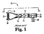
参照により本明細書に援用するWestcott他による特許文献1に記載されているようなタイプのカニューレを、図1〜図3に示す。クランプ装置(カニューレ)10を使用して、灌流カニューレを腎大動脈(renal aorta)34に結合する。クランプ10は、ピン16を中心に枢動する2つの長手方向部材12及び14を含む。部材12の近位端は一体型ハンドル18を含み、部材14の近位端は一体型ハンドル20を含む。部材12の遠位端は、細長く中空で環状の一体型クランプヘッド24を含み、部材14の遠位端は、細長く中空で環状の一体型クランプヘッド26を含む。クランプヘッド26にはニップル28が取り付けられる。ハンドル18及び20を相互に向かって動かして、部材12及び14がピン16を中心に枢動させることにより、部材12及び14のクランプヘッド24及び26を相互から引き離す。ハンドル18及び20を離間するよう付勢するために、ハンドル間にばね22を位置決めする。これはさらに、クランプヘッド24及び26を押し合わせる傾向がある。したがって、部材12及び14の遠位端のクランプヘッド24及び26は、外的圧縮力がハンドル18及び20に加わらない限りは係合して挟持関係になる。内腔32がニップル28を貫通する。
A cannula of the type as described in U.S. Patent No. 5,677,047 by Westcott et al., Which is incorporated herein by reference, is shown in Figs. A perfusion cannula is coupled to the
使用時には、腎臓36等のドナー臓器の腎大動脈34へのクランプ10の取り付けは、クランプ10を開き、腎大動脈34の遠位端38を環状クランプヘッド24に通し、腎大動脈34の遠位端38を環状クランプヘッド24で保持し、クランプヘッド26を環状クランプヘッド24に対して腎大動脈34の遠位端38と係合させるためにクランプ10のハンドルに対する圧力を解放することにより行われる。内腔32を通して腎大動脈34への液体の灌流を提供するために、続いてカテーテル40をニップル28に取り付ける。
In use, attachment of
参照により本明細書に援用するSchein他による特許文献2は、別のタイプのカニューレを開示している。 U.S. Patent No. 5,637,097 to Schein et al., Which is incorporated herein by reference, discloses another type of cannula.
上述したカニューレは、カレルパッチ(Carrel patch)又はカフとしても知られる大動脈パッチの使用を必要とする。大動脈パッチは、臓器が臓器ドナーから摘出される際に臓器に付着した状態の動脈の一部である。大動脈パッチを使用して、提供臓器の血管系のカニュレーションを容易にする。大動脈パッチに必要な大動脈が損傷を受ける結果となるので、大動脈パッチは、通常は死亡したドナーからしか入手可能でない。したがって、上述したカニューレは、大動脈パッチが利用可能でない生体ドナー又は臓器から提供された腎臓等の臓器と共に使用するのに適していないという問題を抱えている。かかる臓器では、カニュレーションに利用可能な組織の量ははるかに少ない。臓器を被提供者に移植する際に臓器を再接続するのに十分な組織が残るように、カニューレの取り付け時に利用可能な限られた量の組織に損傷を与えないよう、また臓器の損失を招き得る損傷を防止するよう注意しなければならない。 The cannulas described above require the use of aortic patches, also known as Carrel patches or cuffs. An aortic patch is a portion of an artery that is attached to the organ when the organ is removed from the organ donor. Aortic patches are used to facilitate cannulation of the donor vasculature. Aortic patches are usually only available from deceased donors because the aorta required for the aortic patch results in damage. Thus, the cannulas described above have the problem that they are not suitable for use with organs such as kidneys provided from living donors or organs where aortic patches are not available. In such organs, the amount of tissue available for cannulation is much less. To ensure that enough tissue remains to reconnect the organ when it is transplanted into the recipient, avoid the damage to the limited amount of tissue available when the cannula is attached, and reduce organ loss. Care must be taken to prevent possible damage.
本明細書に記載の広範な発明原理の例示的な実施態様は、大動脈パッチなしで使用できるカニューレを提供する。例示的な実施態様は、第1円周部と、第2円周部と、第1クランプ面を有するシールとを備えたカニューレを提供する。第1円周部及び第2円周部は、相互に協働して血管系の円周を支持し第2クランプ面を形成するよう構成される。第1クランプ面及び第2クランプ面は、協働して血管系の端を固定するよう構成される。これらの例示的な実施態様は、大動脈パッチを必要とせず、最小量の組織と係合するだけなので、上述の問題及び欠点に対する解決手段を提供する。 Exemplary embodiments of the broad inventive principles described herein provide a cannula that can be used without an aortic patch. An exemplary embodiment provides a cannula with a first circumference, a second circumference, and a seal having a first clamping surface. The first circumferential portion and the second circumferential portion are configured to cooperate with each other to support the circumference of the vascular system and form a second clamping surface. The first clamping surface and the second clamping surface are configured to cooperate to secure the end of the vasculature. These exemplary embodiments provide a solution to the problems and drawbacks described above because they do not require an aortic patch and only engage a minimal amount of tissue.
本明細書に記載の広範な発明原理の例示的な実施態様は、臓器の血管系をカニュレーションする方法を提供する。本方法は、血管系の円周をカニューレの第1円周部及びカニューレの第2円周部で囲み、血管系に液体を流す能力を維持しつつ血管系を支持するステップを含む。本方法は、血管系に液体を流す能力を維持するような様式で血管系の端をカニューレのシール部と接触させて、灌流中の実質的に漏れの無い状態を確保するステップを含む。これらの例示的な実施態様は、大動脈パッチを必要とせず、最小量の組織と係合するだけなので、上述の問題及び欠点に対する解決手段を提供する。 Exemplary embodiments of the broad inventive principles described herein provide a method for cannulating the vasculature of an organ. The method includes the steps of surrounding the circumference of the vasculature with the first circumference of the cannula and the second circumference of the cannula and supporting the vasculature while maintaining the ability to flow fluid through the vasculature. The method includes the step of contacting the end of the vasculature with the cannula seal in a manner that maintains the ability to flow fluid through the vasculature to ensure a substantially leak-free condition during perfusion. These exemplary embodiments provide a solution to the problems and drawbacks described above because they do not require an aortic patch and only engage a minimal amount of tissue.
本明細書に記載の広範な発明原理の例示的な実施態様は、血管系の端がカニューレにより固定された位置にカニューレがある場合に、ユーザが血管系の内部及びシールの少なくとも一部を見ることができるよう構成した光学的透明部を有するカニューレを提供する。光学的透明部は、カニューレにおける動脈の位置に関して動脈の光学的拡大を提供する。これらの例示的な実施態様は、カニュレーション中に損傷及び適切な接続に関する血管系の検査を可能にするので、上述の問題及び欠点に対する解決手段を提供する。拡大は、臨床医による混入気泡又は血塊の観察及び損傷に関する動脈内膜の観察も可能にすることができる。また、カニューレが適切に接続されていることを確認するために組織をカニューレ内で容易に見ることができるので、これらの例示的な実施態様は、血管系からの組織をあまり使用する必要がない。したがって、組織が適切にカニュレーションされていることを確認するために、過剰な組織を使用する必要がない。 An exemplary embodiment of the broad inventive principles described herein provides that the user sees the interior of the vasculature and at least a portion of the seal when the cannula is in a position where the end of the vasculature is secured by the cannula. A cannula having an optically transparent portion configured to be able to be provided. The optical transparency provides optical magnification of the artery with respect to the position of the artery in the cannula. These exemplary embodiments provide a solution to the above-mentioned problems and drawbacks because they allow examination of the vasculature for damage and proper connections during cannulation. The enlargement can also allow the clinician to observe entrained bubbles or blood clots and to observe the arterial intima for damage. Also, these exemplary embodiments require less use of tissue from the vasculature because tissue can be easily viewed within the cannula to ensure that the cannula is properly connected. . Thus, there is no need to use excess tissue to ensure that the tissue is properly cannulated.
添付の図面を参照して、例示的な実施態様を説明することができる。 Exemplary embodiments can be described with reference to the accompanying drawings.
機械灌流による臓器の保存は、コンピュータ制御の有無を問わず低体温で、晶質灌流液(crystalloid perfusates)を使用して酸素付加を行わずに達成されてきた。例えば、参照により本明細書に援用するKlatz他による米国特許第5,149,321号、第5,395,314号、第5,584,804号、第5,709,654号、及び第5,752,929号、並びに米国特許出願第08/484,601号を参照されたい。 Preservation of organs by mechanical perfusion has been achieved at low body temperature with or without computer control and without oxygenation using crystalloid perfusates. See, for example, US Pat. Nos. 5,149,321, 5,395,314, 5,584,804, 5,709,654, and 5, by Klatz et al., Which are incorporated herein by reference. , 752,929, and US patent application Ser. No. 08 / 484,601.
臓器は、温虚血時間を実質的にゼロに制限するようにして入手するのが理想的である。残念ながら、現実には、特に心拍停止ドナーからの多くの臓器は、長い温虚血期間(すなわち、45分以上)後に入手される。低温でのこれらの臓器の機械灌流は、著しい改善を示している(Transpl Int 1996 Daemen)。この目的を達成し、且つ臓器全般を機械灌流するために、多数の制御回路及びポンピング構成が利用されてきた。例えば、参照により本明細書に援用される、Sadriによる米国特許第5,338,662号及び第5,494,822号、Bauer他による米国特許第4,745,759号、Fahy他による米国特許第5,217,860号及び第5,472,876号、Martindale他による米国特許第5,051,352号、Clark他による米国特許第3,995,444号、Gruenbergによる米国特許第4,629,686号、Thome他による米国特許第3,738,914号及び第3,892,628号、Bacchi他による米国特許第5,285,657号及び第5,476,763号、McGhee他による米国特許第5,157,930号、並びにSugimachi他による米国特許第5,141,847号を参照されたい。 Ideally, the organ is obtained in a manner that limits the warm ischemia time to substantially zero. Unfortunately, in reality, many organs, particularly from cardiac arrest donors, are obtained after a long warm ischemic period (ie, over 45 minutes). Mechanical perfusion of these organs at low temperatures shows a marked improvement (Transpl Int 1996 Daemen). A number of control circuits and pumping configurations have been utilized to achieve this goal and to mechanically perfuse the entire organ. For example, U.S. Pat. Nos. 5,338,662 and 5,494,822 to Sadri, U.S. Pat. No. 4,745,759 to Bauer et al., U.S. Pat. To Fahy et al., Incorporated herein by reference. US Pat. Nos. 5,217,860 and 5,472,876, US Pat. No. 5,051,352 by Martindale et al., US Pat. No. 3,995,444 by Clark et al., US Pat. No. 4,629 by Gruenberg US Pat. Nos. 3,686,914 and 3,892,628 by Thome et al., US Pat. Nos. 5,285,657 and 5,476,763 by Bacchi et al., US by McGhee et al. See US Pat. No. 5,157,930 and US Pat. No. 5,141,847 by Sugimachi et al.
本明細書に記載のカニューレ及びクラピング法は、参照により本明細書に援用されるOwenによる米国特許第6,014,864号、第6,183,019号、第6,241,945号、及び第6,485,450号に記載されている。これらの装置及び方法は、臓器の回復及び移植に関するものだが、本明細書に記載のカニューレ及びクランプ法は、流体流を伴ったクランピングが望まれる様々な他の医療手法及びさまざまな他の医療機器でも使用できる。したがって、本明細書に記載のカニューレ及びクランプ法は、例示的な実施態様と共に後述する用途に限定されない。 The cannula and clapping methods described herein are described in US Pat. Nos. 6,014,864, 6,183,019, 6,241,945, and Owen, which are hereby incorporated by reference, and No. 6,485,450. Although these devices and methods relate to organ recovery and transplantation, the cannula and clamp methods described herein are useful for various other medical procedures and various other medical procedures in which clamping with fluid flow is desired. Can also be used with equipment. Thus, the cannula and clamping methods described herein are not limited to the applications described below with exemplary embodiments.
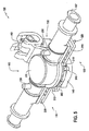
図4は、例示的な第1実施形態による灌流クランプ装置又はカニューレ100を示す。カニューレ100は、例えば灌流機又は灌流システム(図示せず)の配管への接続により、臓器の1つ又は複数の動脈を灌流機又は灌流システムに接続することが可能である。全ての医療用流体接触面は、使用する医療用流体と適合する材料、好ましくは抗血栓性材料で形成又は被覆することが好ましい。
FIG. 4 shows a perfusion clamping device or
灌流用の医療用流体は、任意の適当な医療用流体であり得る。例えば、これは単純な晶質溶液であってもよく、又は適当な酸素キャリアを添加してもよい。酸素キャリアは、例えば、洗浄し安定化した赤血球、架橋ヘモグロビン、ペグ化(pegolated)ヘモグロビン、又はフルオロカーボン系エマルジョンであり得る。医療用流体は、生理環境における過酸化又はフリーラジカルによる損傷を低減することが知られている抗酸化物質、及び組織保護に役立つことが知られている特定の作用物質も含有し得る。さらに、医療用流体は、血液及び血液製剤も含み得る。 The perfusion medical fluid can be any suitable medical fluid. For example, this may be a simple crystalline solution or a suitable oxygen carrier may be added. The oxygen carrier can be, for example, washed and stabilized red blood cells, cross-linked hemoglobin, pegolated hemoglobin, or a fluorocarbon emulsion. Medical fluids may also contain antioxidants known to reduce peroxidation or free radical damage in the physiological environment, and certain agents known to help protect tissues. In addition, medical fluids can include blood and blood products.
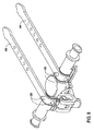
カニューレ100は、図4には開放状態で示し、図5には閉鎖状態で示す。解放状態では、第1円周部110及び第2円周部120が第1ヒンジ150において相互から離れるように回動する。第1円周部及び第2円周部を回動させて相互に接触させると、第2クランプ面134(後述)が形成される。このような閉鎖状態の第1円周部110と第2円周部120との間に血管系を配置すると、血管系の円周が支持される。締結構造140が、第1円周部110及び第2円周部120をこの閉鎖状態で固定する。締結構造140は多数の方法で達成できる。図中では、締結構造140を解除可能なスナップ嵌めとして示すが、ストラップ又はタイ等の他の締結構造にも同様の効果がある。解除可能なスナップ嵌めを使用する場合、血管系をトリミング又は再位置決めできるようにカニューレを破断せずに再開放できる。好ましくは、解除可能なスナップ嵌めは、完全に係合すると「カチッ」等の可聴音を発生させることで、スナップ嵌めが完全に係合したことをユーザが目視検査を行う必要なく知ることができる。
The
第1円周部110及び第2円周部120は、第1ヒンジ150で回転可能に接続されているものとして図示するが、他の接続法が本明細書に記載の広範な発明原理により考えられる。例えば、第1円周部110及び第2円周部120の少なくとも一方を閉鎖前に分離してから、第1円周部110及び第2円周部120の他方にスナップ嵌めしてもよい。代替的に、第1円周部110及び第2円周部120がピン又はレール上で並進してもよい。これら2つの部品間の相対運動の多くの実施態様が、本明細書に記載の広範な発明原理の範囲内にある。
Although the first
第1円周部110及び第2円周部120の両方が、テーパ部190を含む。図6に示すように、テーパ部190は、第1円周部110と第2円周部120との間に形成された円筒形空間200よりも直径が小さい。テーパ部190は、血管系の固定に役立つが、血管系を通る流体流を過度に狭めるべきではない。血管系内の十分な流体流を可能にするために、テーパ部190は、血管系の外径を、第1クランプ面132及び/又は第2クランプ面134における又はその付近における最も狭い点で、例えば約25パーセント未満、好ましくは20パーセント未満、例えば約12パーセント又は約19パーセント狭めることができる。テーパ部190は、円筒部200による血管系の妨害が最小又はゼロとなるよう円筒部200まで急激に拡張することが好ましい。かかる構成は、これを必要としない血管系に過度の狭窄が生じるのを最小限に抑えるか又は完全に回避する。
Both the first
血管系が第1円周部110と第2円周部120との間で支持された後、シール130を血管系の端に接触させる。これは、第2ヒンジ152を介してチャンバ部160を閉鎖位置(図5に示す)へ回動させることにより達成でき、これによりシール130を血管系の端と接触させる。この閉鎖位置では、第1クランプ面132及び第2クランプ面134が血管系の端を固定する。第1クランプ面132及び第2クランプ面134の相補的な円錐面は、血管系の内部への液体の自由な流れを可能するような様式で血管系の端を固定する。当然ながら、血管系の端を固定する他の運動実施態様が、本明細書に記載の広範な発明原理の範囲内にある。
After the vascular system is supported between the first
血管系の内部に出入りする自由流は、流路136により達成することができる。流路136は、同じく円形であり得るシール130を通る円形の孔であり得る。シール130及び流路136の形状は、円形に限定されず、他の設計事項に影響され得る。図7に示すように、シール130は、流路136に円錐部250を含み得る。円錐部250は、セレーション及び/又はローレット180を含むことができ、これらは、第1円周部110及び/又は第2円周部120の相補的なセレーション及び/又はローレット180と共にラビリンス効果を提供し、血管系の端を固定するシールの能力を向上させる。例示的な一実施形態では、円錐部250は約1.5ミリメートル〜3.0ミリメートル延びる。
Free flow into and out of the vasculature can be achieved by the
シール130は、エラストマー材料製であり得る。これは、血管系、特に血管系の外部よりも損傷を受けやすい血管系の内部に対する損傷を防止するのに役立つ。シール130のショアA硬度(デュロメータとしても知られている)は、約32〜80の範囲内、又は約60〜約70等のそれよりも小さな任意の範囲内になるよう選択され得る。例として、デュロメータは、約35、40、45、50、55、60、65、70、75、又は80であり得る。本明細書で用いられる場合、用語「約」は、固有の製造公差及び測定誤差を説明するためのものである。硬度は、カニュレーション対象の血管系の必要に応じてそれらの範囲内又は範囲外でさらに調整することができる。さまざまな硬度のシール130及び/又は流路136のサイズが異なるシール130をカニューレ100と共に含んで、種々の血管系と共に使用できるキットを形成することができる。
The
シール130は、チャンバ部160のチャンバ162の第1開口(表示せず)と噛み合う。流路136は、血管系からチャンバ162への液体連通を可能にする。チャンバ部160は、チャンバと流体連通する第2開口166及び第3開口168も含む。第2開口166及び第3開口168は、「横方向の」流体流、すなわち、カニューレを取り付ける組織に出入りする流体流の方向に対して実質的に垂直な流体の流れを提供する。例えば、カニューレの1つ又は複数のフィッティングは、流路136に出入りする流体流の軸に対して実質的に垂直な流体流軸を有する向きである。この「横方向」流体流配置は、例えば米国特許第7,678,563号及び米国特許出願公開第2004/0221719号に記載されているように、カニューレを実質的に単一平面内にある臓器運搬装置の配管に接続させることができ、上記文献の両方を参照により本明細書に援用する。さらに、複数のカニューレを実質的に同じ平面内で接続するだけでなく相互接続することができる。
The
第2開口166及び第3開口168の一方又は両方を、プライミング及び/又は気泡除去に利用されるフィッティング107に接続することができる。第2フィッティング107は、こうした目的でポート又は弁を備える。第2開口166及び第3開口168を使用して、例えば配管を接続することにより複数のカニューレをネットワーク化することもでき、この接続は、例えば分割注入ライン(split infuse line)を各カニューレの第1フィッティングまで通すことにより並列に、又は例えばカニューレの第1フィッティングを別のカニューレの第2フィッティングに接続することにより直列に行われる。標準的なルアーの幾何形態又は他の適当な構造をフィッティングに用いてもよい。
One or both of the
チャンバ部160は、光学的透明部170を含み得る。光学的透明部170は、カニューレの内部の目視検査を可能にする。これは、ユーザがカニューレ内の血管系のクランピングを検査すること、及び血管系の損傷又はカニューレ内の若しくはカニューレを流れる気泡等の他の物を検査することを可能にするという点で、特に有利である。光学的透明部は、比較的小さくおそらく直径3ミリメートル〜7ミリメートルであり得る血管系をより詳細に見ることができるように、光学的拡大を提供することができる。
The
チャンバ部160は、チャンバ部の壁に配置されシール130の外周に係合するよう構成したシール係合部262を含み得る。図7に示す例示的な係合部は、概してリング形だが、シール130との確実な係合を容易にする任意の形状とすることができる。シール係合部262は、シール130の機能を著しく改善することができる。チャンバ部160は、シール130を支持してシール130の過度の撓み又は圧潰を防止する支持体165も含み得る。図7は、略矩形の断面を有する2つのかかる支持体165を含み、さらに2つの支持体165は見えない断面を示すが、任意の形状を有する任意の数の支持体が本明細書に記載の広範な発明原理に包含される。支持体165は、シール係合部262よりもチャンバ部160の中心に近いように図示されており、支持体165は、シール130の中心にも相当するチャンバ部160の中心の周りで等間隔且つ径方向に離間している。かかる支持体は、比較的軟質のエラストマー材料製であるシール130がチャンバ160内で「裏返し」になり得ることでシール130がそのシール機能を適切に果たすのを妨げ得る可能性を低減するか又は完全に回避する。
The
図4に示すように、第1円周部110及び第2円周部120の両方が表面220を含み、これは、第2クランプ面134の直径の外側にあり、第1円周部110及び第2円周部120内で支持される血管系の円周に対して略垂直である。この表面は、セレーション及び/又はローレット180を含む。かかるセレーション及び/又はローレット180は、血管系のさらなる組織を固定するために含まれ得る。図6に示すように、表面220の反対側に、長手方向補強リブ320を設けて、表面220の剛性を高めることができる。カニューレ110は、大動脈パッチなしで血管系を固定する際に完全に機能するが、表面220及びセレーション及び/又はローレット180は、チャンバ部160の対応構造(表示せず)と協働して大動脈パッチを任意に固定する。したがって、本明細書に記載の広範な発明原理の例示的な実施形態は、大動脈パッチの有無を問わず使用できるカニューレを提供する。例えば、腎臓をカニュレーションする場合、腎動脈の大部分が存在する場合又はしない場合がある。したがって、カニューレ100は、いずれの状況でも効果的に使用できる。
As shown in FIG. 4, both the first
セレーション及び/又はローレット180は、第2クランプ面134にも含まれ得る。特に、そうしなければ第1クランプ面132からの血管系の内部との接触が血管系に対する許容不可能な損傷を引き起こすであろう場合、セレーション及び/又はローレット180を第1クランプ面132から省くことができる。シール130の(したがって、第2クランプ面132の)比較的軟質のエラストマー材料は、セレーション及び/又はローレット180がシール130に存在する場合でも血管系の内面の損傷を防止するのに役立ち得る。動脈内膜に入るシールの長さは最小化され、したがって動脈内の損傷が最小化される。
Serrations and / or
ノッチ210も、第1円周部110及び第2円周部120の一方又は両方に含まれ得る。4つのかかるノッチを図4に示す。各ノッチ210を使用して、縫合糸又は血管系の側枝を固定することができる。縫合糸は、側枝に取り付けることができる。
The
1つ又は複数のクリート300も、第1円周部110及び第2円周部120の一方又は両方に含まれ得る。円周部にわたって等間隔に(例えば、90度毎に)分配した4つのかかるクリートを図4に示すが、任意の数のクリートを任意の間隔で設けることができる。各クリート300を使用して、例えば、縫合糸又は血管系の側枝を固定することができる。縫合糸は、側枝に取り付けることができる。かかるクリートは、縫合糸又は側枝をクリートに巻き付けるか又は縛り付けることができるよう構成され得る。好適なクリートは、概して柱状の突起である。好ましくは、柱状形状は、柱の長さに沿って又は柱の端に拡大部310を含むことができ、拡大部310は、縫合糸又は側枝がクリートから滑って外れないようにする障害を提供するような形状及び位置付けにされる。好ましくは、クリート300は、縫合糸又は側枝が拡大部310とクリート300を含む第1円周部110及び第2円周部120のいずれかとの間でクリート300に取り付けられるよう構成される。クリート300は、概ね矩形又は正方形の断面で図示されているが、断面は、使用し易さ及び/又は製造し易さを促す必要に応じて任意の形状とすることができる。
One or
図5は、4つの柱230を含む。これらの柱を使用して、チャンバ部160を第1円周部110及び第2円周部120に締結してカニューレ100を閉鎖状態に保つようカニューレに巻き付く1つ又は複数のストラップ400を繋止することができる。単一の柱230を使用して各ストラップ400を繋止できるが、2つ以上の柱230が含まれる場合、接着剤等の付加的な締結構造を使用せずにストラップ400をチャンバ部160に締結できるので、製造及び使用のし易さを改善することができ、且つ/又は製造費を減らすことができる。図5は、2つの柱230の2つの群を示す。図8の例示的な実施形態では、各柱群の各柱230をカニューレの表面にわたって相互から約90度に配置する。すなわち、各群の柱230は相互に対して略垂直だが、他の相対位置も考えられる。好ましくは、各群の柱230の相対位置は、柱230の各群に取り付けたストラップ400が接着剤の必要をなくすよう選択される。ストラップ400が含まれる場合、補強リブ320は、ストラップ400の位置付けを容易にすると共にストラップの横方向移動を阻止又は防止するために凹部330を含み得る。スナップ嵌め又はラチェット機構等の代替的な構造を使用して、チャンバ部160を第1円周部110及び第2円周部120に締結することもできる。
FIG. 5 includes four
例示的な実施態様では、第1ヒンジ150及び第2ヒンジ152の両方が運動に対するある程度の剛性又は抵抗性を含み得ることで、外力が加わらない限り両方のヒンジが任意の部分的な又は完全な開放状態又は閉鎖状態に留まるようにする。かかる剛性又は抵抗性は、ヒンジの噛み合い部に締まり嵌め又は線対線嵌め(line-to-line fit)を設けることにより、ヒンジで達成できる。これにより、ヒンジが望ましくない位置に動くことなくユーザがヒンジを任意の所望の位置に配置することができることで、ユーザが自由に片手だけでカニューレを保持できると共にユーザのもう一方の手を他の作業のために空けておくことができるので、使用し易さが促される。
In an exemplary embodiment, both the
例示的な一実施形態では、カニューレが、第1円周部と、第2円周部と、第1クランプ面を有するシールとを備え、第1円周部及び第2円周部は、相互に協働して血管系の外周全体を支持し且つ第2クランプ面を形成するよう構成され、第1クランプ面及び第2クランプ面は、協働して第1クランプ面と第2クランプ面との間で血管系の端を固定するよう構成される。第1クランプ面及び第2クランプ面は、相補的な円錐面を含む。第1円周部及び第2円周部はそれぞれ、第1円周部及び第2円周部を合わせて血管系の円周の周りで協働して締結するための少なくとも1つの締結構造を含む。第1円周部及び第2円周部の少なくとも一方は、第1円周部及び第2円周部の他方に対して可動である。第1ヒンジが、第1円周部及び第2円周部を接続する。流路がシールに配置され、流路は、血管系の内部との流体連通を可能にするよう構成される。チャンバ部は、チャンバと流体連通する第1開口及び第2開口を有し、シールは、第1開口と噛み合うよう構成される。チャンバ部は、チャンバと流体連通する第3開口を備える。チャンバ部は、第1円周部及び第2円周部の少なくとも一方に対して可動である。チャンバ部は、第1円周部及び第2円周部の少なくとも一方にヒンジにより接続される。血管系の端が固定された位置にカニューレがある場合、シールは、チャンバ部と、第1円周部と、第2円周部との間に配置される。In an exemplary embodiment, the cannula includes a first circumferential portion, a second circumferential portion, and a seal having a first clamping surface, wherein the first circumferential portion and the second circumferential portion are mutually In cooperation with each other to support the entire outer circumference of the vasculature and to form a second clamping surface, the first clamping surface and the second clamping surface cooperating with the first clamping surface and the second clamping surface. Configured to secure the end of the vasculature between. The first clamping surface and the second clamping surface include complementary conical surfaces. Each of the first circumferential portion and the second circumferential portion includes at least one fastening structure for jointly fastening the first circumferential portion and the second circumferential portion around the circumference of the vascular system. Including. At least one of the first circumferential portion and the second circumferential portion is movable with respect to the other of the first circumferential portion and the second circumferential portion. A first hinge connects the first circumferential portion and the second circumferential portion. A flow path is disposed on the seal and the flow path is configured to allow fluid communication with the interior of the vasculature. The chamber portion has a first opening and a second opening in fluid communication with the chamber, and the seal is configured to mate with the first opening. The chamber portion includes a third opening in fluid communication with the chamber. The chamber portion is movable with respect to at least one of the first circumferential portion and the second circumferential portion. The chamber portion is connected to at least one of the first circumferential portion and the second circumferential portion by a hinge. When the cannula is in a position where the end of the vasculature is fixed, the seal is disposed between the chamber portion, the first circumferential portion, and the second circumferential portion.
カニューレは、血管系の端が固定された位置にカニューレがある場合に、ユーザが血管系の内部及びシールの少なくとも一方を見ることができるよう構成した光学的透明部を備える。光学的透明部は光学的拡大を提供する。シールはエラストマー材料を含む。エラストマー材料は、約32〜約70のショアA硬度を有し得る。エラストマー材料は、約60〜約65のショアA硬度を有し得る。第2クランプ面は、セレーション及びローレットの少なくとも一方を備える。第1円周部及び第2円周部はそれぞれ、第1円周部と第2円周部との間に形成された実質的に円筒形の空間よりも小さな直径を有するテーパ部を備える。小さな直径は、実質的に円筒形の空間の直径よりも12パーセント以下だけ小さい。第1円周部及び第2円周部の少なくとも一方は、縫合糸又は血管系の側枝を固定するよう構成したノッチを備える。第1円周部及び第2円周部の少なくとも一方は、第2クランプ面の直径の外側に位置付けた表面を備え、この表面は、円周に対して略垂直であり、少なくとも1つのセレーション又はローレットを備える。締結構造は、カニューレが閉鎖状態にある場合に、チャンバ部を第1円周部及び第2円周部の少なくとも一方に固定するよう構成される。締結構造はエラストマーストラップであり得る。締結構造はスナップ嵌めであり得る。締結構造はラチェット機構であり得る。カニューレは、種々のサイズの血管系用に構成した複数の交換可能なシールを備えたキットの形態であり得る。The cannula includes an optical transparency configured to allow a user to view at least one of the interior of the vasculature and / or the seal when the cannula is in a position where the end of the vasculature is fixed. The optical transparency provides optical magnification. The seal includes an elastomeric material. The elastomeric material may have a Shore A hardness of about 32 to about 70. The elastomeric material may have a Shore A hardness of about 60 to about 65. The second clamping surface includes at least one of serrations and knurls. Each of the first circumferential portion and the second circumferential portion includes a tapered portion having a smaller diameter than the substantially cylindrical space formed between the first circumferential portion and the second circumferential portion. The small diameter is no more than 12 percent less than the diameter of the substantially cylindrical space. At least one of the first circumferential portion and the second circumferential portion includes a notch configured to secure a suture or a side branch of the vascular system. At least one of the first circumferential portion and the second circumferential portion comprises a surface positioned outside the diameter of the second clamping surface, the surface being substantially perpendicular to the circumference and having at least one serration or Provide knurling. The fastening structure is configured to secure the chamber portion to at least one of the first circumferential portion and the second circumferential portion when the cannula is in a closed state. The fastening structure can be an elastomer strap. The fastening structure can be a snap fit. The fastening structure can be a ratchet mechanism. The cannula can be in the form of a kit with a plurality of replaceable seals configured for various sized vasculature.
血管系の円周をカニューレの第1円周部及びカニューレの第2円周部で囲み、血管系に液体を流す能力を維持しつつ血管系を支持するステップと、血管系に液体を流す能力を維持するような様式で血管系の端をカニューレのシール部と接触させるステップとを含む、臓器の血管系をカニュレーションする方法を開示する。臓器は腎臓とすることができ、血管系は大動脈パッチを含まない。血管系の円周は、12パーセントよりも圧縮されない。本方法は、シール部と第1円周部及び第2円周部の少なくとも一方との間で血管系の端をクランプするステップをさらに含み得る。本方法は、セレーション及びローレットの少なくとも一方を血管系の端から2ミリメートル未満で血管系と係合させるステップをさらに含み得る。The ability to surround the circumference of the vasculature with the first circumference of the cannula and the second circumference of the cannula and to support the vasculature while maintaining the ability to flow liquid to the vasculature; Contacting the end of the vasculature with the seal of the cannula in such a manner as to maintain the cannula. The organ can be the kidney and the vasculature does not contain aortic patches. The circumference of the vasculature is less than 12 percent compressed. The method may further include clamping the end of the vasculature between the seal portion and at least one of the first circumferential portion and the second circumferential portion. The method may further include engaging at least one of the serration and knurl with the vasculature less than 2 millimeters from the end of the vasculature.
別の例示的な実施形態では、大動脈パッチなしの腎臓の血管系用のカニューレを開示する。カニューレは、血管系の円周をカニューレの第1円周部及びカニューレの第2円周部と接触させ、血管系に液体を流す能力を維持しつつ血管系の外周全体を支持する手段と、血管系に液体を流すと共に血管系をカニューレのシール部と第1円周部及び第2円周部の組み合わせとの間で固定する能力を維持するような様式で、血管系の端をシール部と接触させる手段とを備える。In another exemplary embodiment, a cannula for the renal vasculature without an aortic patch is disclosed. The cannula has a means for contacting the circumference of the vasculature with the first circumference of the cannula and the second circumference of the cannula and supporting the entire circumference of the vasculature while maintaining the ability to flow fluid through the vasculature; The end of the vasculature is sealed in a manner that allows fluid to flow through the vasculature and maintain the ability to secure the vasculature between the seal portion of the cannula and the combination of the first and second circumferences. And a means for bringing into contact therewith.
別の例示的な実施形態では、カニューレが、血管系の端が固定された位置にカニューレがある場合に、ユーザが血管系の内部及びシールの少なくとも一方を見ることができるよう構成した光学的透明部を含み、光学的透明部は、血管系の内部及びシールの少なくとも一方の光学的拡大を提供する。In another exemplary embodiment, the cannula is optically transparent configured to allow a user to view at least one of the interior of the vasculature and the seal when the cannula is in a position where the end of the vasculature is fixed The optically transparent portion provides an optical enlargement of the interior of the vasculature and / or the seal.
別の例示的な実施形態では、カニューレが、第1クランプ面と、第1クランプ面に対向する第2クランプ面と、血管系の長さを包囲するよう構成した円周部であり、血管系の一部が円周部及び第1クランプ面を通過できると共に、第1クランプ面及び第2クランプ面が協働して血管系の端を第1クランプ面と第2クランプ面との間に固定するよう構成されるように配置した円周部と、血管系の側枝及び血管系及び臓器の少なくとも一方に配置した縫合糸の少なくとも一方を締結するよう構成したファスナとを備える。ファスナは、第1クランプ面の周囲に配置した少なくとも1つのノッチを含む。ファスナは、第1クランプ面の周囲から延びる少なくとも1つの突起を含み、突起は、側枝及び縫合糸の少なくとも一方を突起に巻き付けることを可能にするよう構成される。突起は拡大部を備え、拡大部は、縫合糸又は側枝が第1クランプ面の周囲と拡大部との間で突起に締結されると縫合糸又は側枝が突起から滑って外れるのを防止するよう構成される。ファスナは、第1クランプ面の周囲から延びて側枝及び縫合糸の少なくとも一方を巻き付けられるよう構成した突起と、第1クランプ面の周囲に配置した少なくとも1つのノッチとを任意に含み得る。少なくとも1つのノッチは、少なくとも1つの突起に隣接して配置される。In another exemplary embodiment, the cannula is a first clamping surface, a second clamping surface opposite the first clamping surface, and a circumference configured to surround the length of the vasculature; Can pass through the circumference and the first clamping surface, and the first clamping surface and the second clamping surface cooperate to fix the end of the vascular system between the first clamping surface and the second clamping surface. And a fastener configured to fasten at least one of the sutures disposed on at least one of the vascular system and at least one of the vascular system and the organ. The fastener includes at least one notch disposed around the first clamping surface. The fastener includes at least one protrusion extending from the periphery of the first clamping surface, the protrusion being configured to allow at least one of the side branch and the suture to be wrapped around the protrusion. The protrusion includes an enlarged portion that prevents the suture or side branch from sliding off the protrusion when the suture or side branch is fastened to the protrusion between the periphery of the first clamping surface and the enlarged portion. Composed. The fastener may optionally include a protrusion extending from the periphery of the first clamping surface and configured to wrap around at least one of the side branch and the suture, and at least one notch disposed around the first clamping surface. The at least one notch is disposed adjacent to the at least one protrusion.
別の例示的な実施形態では、臓器又は血管系をカニュレーションする方法が、臓器又は組織の血管系をカニューレの円周部に挿入し、血管系をカニューレの第1クランプ面に通すステップと、縫合糸及び血管系の側枝の少なくとも一方を締結構造に締結するステップと、血管系を第1クランプ面と第2クランプ面との間にクランプするステップとを含む。側枝及び縫合糸の少なくとも一方を締結するステップは、側枝及び縫合糸の少なくとも一方を第1クランプ面の周囲のノッチに挿入するステップを含む。側枝及び縫合糸の少なくとも一方を締結するステップは、側枝及び縫合糸の少なくとも一方を第1クランプ面の周囲から延びる突起に巻き付けるステップを含む。側枝及び縫合糸の少なくとも一方を締結するステップは、側枝及び縫合糸の少なくとも一方を第1クランプ面の周囲のノッチに挿入するステップと、側枝及び縫合糸の少なくとも一方を第1クランプ面の周囲から延びる突起に巻き付けるステップとを含む。In another exemplary embodiment, a method of cannulating an organ or vasculature includes inserting the organ or tissue vasculature into the circumference of the cannula and passing the vasculature through a first clamping surface of the cannula. Fastening at least one of the suture and the side branch of the vasculature to the fastening structure and clamping the vasculature between the first clamping surface and the second clamping surface. Fastening at least one of the side branch and the suture includes inserting at least one of the side branch and the suture into a notch around the first clamping surface. The step of fastening at least one of the side branch and the suture includes the step of winding at least one of the side branch and the suture around a protrusion extending from the periphery of the first clamping surface. The step of fastening at least one of the side branch and the suture includes inserting at least one of the side branch and the suture into a notch around the first clamping surface, and at least one of the side branch and the suture from the circumference of the first clamping surface. Wrapping around the extending protrusion.
別の例示的な実施形態では、カニューレが、第1クランプ面と、第1クランプ面に対向する第2クランプ面と、カニューレに巻き付いて第1クランプ面及び第2クランプ面を閉鎖位置に保持するよう構成した少なくとも1つのストラップと、少なくとも1つのストラップをカニューレに取り付けるための少なくとも2つの柱とを含む。少なくとも2つの柱は、カニューレの表面にわたって相互に約90度離間させて配置される。少なくとも2つの柱は、接着剤なしで少なくとも2つのストラップをカニューレに取り付ける。In another exemplary embodiment, the cannula wraps around the first clamping surface, the second clamping surface opposite the first clamping surface, and holds the first and second clamping surfaces in the closed position. At least one strap configured as described above and at least two posts for attaching the at least one strap to the cannula. The at least two columns are disposed about 90 degrees apart from each other across the surface of the cannula. At least two posts attach at least two straps to the cannula without adhesive.
別の例示的な実施形態では、カニューレが、第1クランプ面と、第1クランプ面に対向する第2クランプ面であり、第1クランプ面及び第2クランプ面は、協働して血管系開口(a vasculature opening)を第1クランプ面と第2クランプ面との間に固定するよう構成される、第2クランプ面と、組織を第1クランプ面及び第2クランプ面の外側に保持するよう構成した第1クランプ面外の組織支持面と、組織支持面を補強する補強リブとを含む。組織支持面はセレーション又はローレットを備える。カニューレは、カニューレを閉鎖位置に保持するストラップをさらに含み、補強リブは、ストラップの横方向運動を制限するよう構成した凹部を備える。In another exemplary embodiment, the cannula is a first clamping surface and a second clamping surface opposite the first clamping surface, wherein the first clamping surface and the second clamping surface cooperate to provide a vasculature opening. A second clamping surface configured to secure (a vasculature opening) between the first clamping surface and the second clamping surface, and configured to hold tissue outside the first clamping surface and the second clamping surface. A tissue support surface outside the first clamp surface and a reinforcing rib for reinforcing the tissue support surface. The tissue support surface comprises serrations or knurls. The cannula further includes a strap that holds the cannula in the closed position, and the reinforcing rib comprises a recess configured to limit lateral movement of the strap.
別の例示的な実施形態では、カニューレが、可撓性材料を含む第1クランプ面と、第1クランプ面に対向する第2クランプ面と、チャンバ、開口、開口の周りのシール係合部を備えたチャンバ部であり、シール係合部は、第1クランプ面の周囲と係合してこれを支持するチャンバ部と、第2クランプ面の方向から第1クランプ面に加わる力に対抗するように第1クランプ面を支持するチャンバ内の少なくとも1つの支持体であり、シール係合部よりも第1クランプ面の中心の近くに配置した少なくとも1つの支持体とを含む。カニューレは、複数の支持体を含むことができ、支持体は、第1クランプ面の中心の周りで等間隔且つ径方向に離間している。少なくとも1つの支持体は、チャンバの壁に取り付けられてそこから延びる。In another exemplary embodiment, the cannula includes a first clamping surface that includes a flexible material, a second clamping surface opposite the first clamping surface, and a chamber, opening, and seal engagement around the opening. A seal engaging portion that engages with and supports the periphery of the first clamping surface and a force applied to the first clamping surface from the direction of the second clamping surface. And at least one support in the chamber that supports the first clamping surface, and includes at least one support disposed closer to the center of the first clamping surface than the seal engaging portion. The cannula can include a plurality of supports, the supports being equally spaced and radially spaced about the center of the first clamping surface. At least one support is attached to and extends from the chamber wall.
さまざまな特徴を上記の例と共に記載したが、これらの特徴及び/又は例のさまざまな代替形態、変更形態、変形形態、及び/又は改良形態が可能であり得る。したがって、上述した例は説明のためのものである。基礎となる発明原理の広範な趣旨及び範囲から逸脱せずに、さまざまな変更を加えることができる。Although various features have been described in conjunction with the above examples, various alternatives, modifications, variations, and / or improvements to these features and / or examples may be possible. Therefore, the above example is for illustration purposes. Various changes can be made without departing from the broad spirit and scope of the underlying inventive principles.
Claims (13)
第2円周部と、
ストラップと、
第1クランプ面を有するシールと
を備えたカニューレであって、前記第1円周部及び前記第2円周部は、相互に協働して
血管系の外周全体を支持し、且つ
第2クランプ面を形成するよう構成され、
前記第1クランプ面及び前記第2クランプ面は、協働して前記第1クランプ面と前記第2クランプ面との間で前記血管系の端を固定するよう構成され、
前記ストラップが、前記カニューレに巻き付き、前記第1クランプ面及び前記第2クランプ面を閉鎖位置に保持するように構成される、カニューレ。 A first circumference,
A second circumference,
With straps,
A cannula having a seal having a first clamping surface, wherein the first circumferential portion and the second circumferential portion cooperate with each other to support the entire outer circumference of the vascular system, and the second clamp Configured to form a surface,
The first clamping surface and the second clamping surface are configured to cooperate to fix an end of the vasculature between the first clamping surface and the second clamping surface ;
A cannula wherein the strap is configured to wrap around the cannula and hold the first clamping surface and the second clamping surface in a closed position .
前記第1円周部及び前記第2円周部を第1ヒンジにより接続したカニューレ。 The cannula according to any one of claims 1 to 3, wherein at least one of the first circumferential portion and the second circumferential portion is connected to the other of the first circumferential portion and the second circumferential portion. It is movable against
A cannula in which the first circumferential portion and the second circumferential portion are connected by a first hinge.
前記血管系の前記端が固定された位置に前記カニューレがある場合に、前記シールは、チャンバ部と、前記第1円周部と、前記第2円周部との間に配置され、前記シールはエラストマー材料を含むカニューレ。 The cannula according to any one of claims 1 to 4, further comprising a channel disposed in the seal, the channel configured to allow fluid communication with the interior of the vasculature,
If the end of the vascular system is the cannula position fixed, the seal is disposed between the switch Yanba portion, said first circumferential portion, and the second circumferential portion, the The seal is a cannula containing an elastomeric material.
前記チャンバ部は、前記チャンバと流体連通する第3開口を備え、
前記チャンバ部は、前記第1円周部及び前記第2円周部の少なくとも一方に対して可動であり、
前記チャンバ部を、前記第1円周部及び前記第2円周部の少なくとも一方にヒンジにより接続したカニューレ。 The cannula according to any one of claims 1 to 5, further comprising a chamber portion having a first opening and a second opening in fluid communication with the chamber, wherein the seal is configured to mate with the first opening,
The chamber portion includes a third opening in fluid communication with the chamber;
The chamber portion is movable with respect to at least one of the first circumferential portion and the second circumferential portion;
A cannula in which the chamber portion is connected to at least one of the first circumferential portion and the second circumferential portion by a hinge.
前記小さな直径は、前記実質的に円筒形の空間の直径よりも12パーセント以下だけ小さく、
前記第1円周部及び前記第2円周部の少なくとも一方は、前記第2クランプ面の直径の外側に位置付けた表面を有し、該表面は、前記第1円周部及び前記第2円周部内で支持される前記血管系の方向に対して略垂直であり、少なくとも1つのセレーション又はローレットを備えるカニューレ。 The cannula according to any one of claims 1 to 9, wherein each of the first circumferential portion and the second circumferential portion is formed between the first circumferential portion and the second circumferential portion. A tapered portion having a diameter smaller than the diameter of the substantially cylindrical space formed,
The small diameter is no more than 12 percent less than the diameter of the substantially cylindrical space;
At least one of the first circumferential portion and the second circumferential portion has a surface positioned outside the diameter of the second clamp surface, and the surface includes the first circumferential portion and the second circle. A cannula substantially perpendicular to the direction of the vasculature supported within the perimeter and comprising at least one serration or knurl.
前記締結構造はエラストマーストリップであるか、
前記締結構造はスナップ嵌めであるか、
前記締結構造はラチェット機構である、カニューレ。 7. The cannula according to claim 6, further comprising a fastening structure configured to fix the chamber portion to at least one of the first circumferential portion and the second circumferential portion when the cannula is in a closed state. ,
The fastening structure elastomeric strip der Luke,
The fastening structure is a snap-fit der Luke,
Wherein the fastening structure is a ratchet mechanism, the cannula.
Applications Claiming Priority (5)
| Application Number | Priority Date | Filing Date | Title |
|---|---|---|---|
| US13/097,789 | 2011-04-29 | ||
| US13/097,789 US9022978B2 (en) | 2011-04-29 | 2011-04-29 | Universal sealring cannula |
| US13/283,166 US9642625B2 (en) | 2011-04-29 | 2011-10-27 | Cannula for a donor organ with or without an aortic cuff or patch |
| US13/283,166 | 2011-10-27 | ||
| PCT/US2012/033234 WO2012148685A1 (en) | 2011-04-29 | 2012-04-12 | Living donor cannula |
Publications (2)
| Publication Number | Publication Date |
|---|---|
| JP2014518680A JP2014518680A (en) | 2014-08-07 |
| JP6058635B2 true JP6058635B2 (en) | 2017-01-11 |
Family
ID=45976552
Family Applications (1)
| Application Number | Title | Priority Date | Filing Date |
|---|---|---|---|
| JP2014508387A Active JP6058635B2 (en) | 2011-04-29 | 2012-04-12 | Cannula for donor organ with or without aortic cuff or patch |
Country Status (8)
| Country | Link |
|---|---|
| US (1) | US9642625B2 (en) |
| EP (5) | EP3473191B1 (en) |
| JP (1) | JP6058635B2 (en) |
| CN (1) | CN103648411B (en) |
| DK (1) | DK2704644T3 (en) |
| ES (1) | ES2860902T3 (en) |
| PL (1) | PL2704644T3 (en) |
| WO (1) | WO2012148685A1 (en) |
Families Citing this family (13)
| Publication number | Priority date | Publication date | Assignee | Title |
|---|---|---|---|---|
| US8409846B2 (en) | 1997-09-23 | 2013-04-02 | The United States Of America As Represented By The Department Of Veteran Affairs | Compositions, methods and devices for maintaining an organ |
| US8304181B2 (en) | 2004-10-07 | 2012-11-06 | Transmedics, Inc. | Method for ex-vivo organ care and for using lactate as an indication of donor organ status |
| US8465970B2 (en) | 2004-10-07 | 2013-06-18 | Transmedics, Inc. | Systems and methods for ex-vivo organ care |
| US9078428B2 (en) | 2005-06-28 | 2015-07-14 | Transmedics, Inc. | Systems, methods, compositions and solutions for perfusing an organ |
| US9457179B2 (en) | 2007-03-20 | 2016-10-04 | Transmedics, Inc. | Systems for monitoring and applying electrical currents in an organ perfusion system |
| US10750738B2 (en) | 2008-01-31 | 2020-08-25 | Transmedics, Inc. | Systems and methods for ex vivo lung care |
| AU2012242578B2 (en) | 2011-04-14 | 2016-07-21 | Transmedics, Inc. | Organ care solution for ex-vivo machine perfusion of donor lungs |
| US9259562B2 (en) | 2012-07-10 | 2016-02-16 | Lifeline Scientific, Inc. | Cannula |
| US8814889B2 (en) | 2012-07-10 | 2014-08-26 | Lifeline Scientific, Inc. | Cannula with floating clamp member |
| AU2015271799B2 (en) | 2014-06-02 | 2019-07-11 | Transmedics, Inc. | Ex vivo organ care system |
| EP3229588A4 (en) | 2014-12-12 | 2019-03-13 | Freed, Darren | Apparatus and method for organ perfusion |
| CA2997267A1 (en) * | 2015-09-09 | 2017-03-16 | Transmedics, Inc. | Aortic cannula for ex vivo organ care system |
| US11602146B2 (en) | 2017-03-30 | 2023-03-14 | National University Corporation Kitami Institute Of Technology | Connector and fluid supply system |
Family Cites Families (89)
| Publication number | Priority date | Publication date | Assignee | Title |
|---|---|---|---|---|
| US3406531A (en) | 1964-08-25 | 1968-10-22 | Emil S. Swenson | Apparatus for maintaining organs in a completely viable state |
| US3545221A (en) | 1967-05-22 | 1970-12-08 | Swenko Research & Dev Inc | Apparatus for maintaining organs in vitro in a completely viable state |
| FR1577356A (en) | 1968-04-04 | 1969-08-08 | ||
| US3538915A (en) | 1968-09-12 | 1970-11-10 | Deseret Pharma | Infustion device and method |
| SE323475B (en) | 1968-11-26 | 1970-05-04 | Aga Ab | |
| US3892628A (en) | 1969-10-06 | 1975-07-01 | Baxter Laboratories Inc | Preservation of organs |
| BE755423A (en) | 1969-10-06 | 1971-02-01 | Baxter Laboratories Inc | PROCESS AND APPARATUS FOR ORGAN PRESERVATION |
| US3660241A (en) | 1970-01-12 | 1972-05-02 | Baxter Laboratories Inc | Container for organ perfusion or the like |
| US3810367A (en) | 1970-07-16 | 1974-05-14 | W Peterson | Container for cooling, storage, and shipping of human organ for transplant |
| US3935065A (en) | 1971-09-02 | 1976-01-27 | Roland Karl Doerig | Procedure for conservation of living organs and apparatus for the execution of this procedure |
| DE2241698C2 (en) | 1971-09-02 | 1982-08-26 | Roland Dr.med. Zürich Doerig | Process for organ preservation and device for carrying out this process |
| US3777507A (en) | 1971-11-24 | 1973-12-11 | Waters Instr Inc | Renal preservation system |
| US3881990A (en) | 1971-11-24 | 1975-05-06 | Waters Instr Inc | Method of transporting and storing organs while retaining the organs in a viable condition |
| US3843455A (en) | 1972-09-13 | 1974-10-22 | M Bier | Apparatus and technique for preservation of isolated organs through perfusion |
| US3877843A (en) | 1973-05-21 | 1975-04-15 | Baxter Laboratories Inc | Pulsatile pumping system |
| GB1505349A (en) | 1974-06-24 | 1978-03-30 | Abbott Lab | Device for securing a length of cannula or catheter tubing to facilitate the introduction of fluids into the tubing |
| US3995444A (en) | 1974-11-08 | 1976-12-07 | American Hospital Supply Corporation | Organ perfusion system |
| SU760972A1 (en) | 1976-03-18 | 1980-09-07 | Ir G Med Inst | Apparatus for hypothermy |
| US4112944A (en) | 1976-12-13 | 1978-09-12 | Williams Gayland M | Tube clamp and piercing device |
| US4186565A (en) | 1978-05-19 | 1980-02-05 | Henry Ford Hospital | Perfusion system for organ preservation |
| US4242883A (en) | 1979-04-02 | 1981-01-06 | Henry Ford Hospital | Liver preservation |
| US4629686A (en) | 1982-02-19 | 1986-12-16 | Endotronics, Inc. | Apparatus for delivering a controlled dosage of a chemical substance |
| CA1200507A (en) | 1982-06-04 | 1986-02-11 | Nobuo Sakao | Method of preserving organ and apparatus for preserving the same |
| US4473637A (en) | 1982-11-10 | 1984-09-25 | Guibert, Colman & Associates | System for processing an organ preparatory to transplant |
| US4474016A (en) | 1983-03-04 | 1984-10-02 | Baxter Travenol Laboratories, Inc. | Sterile cooling system |
| US4837390A (en) | 1983-05-11 | 1989-06-06 | Keyes Offshore, Inc. | Hyperbaric organ preservation apparatus and method for preserving living organs |
| US4462215A (en) | 1983-05-31 | 1984-07-31 | Hoxan Corporation | Method of preserving organ and apparatus for preserving the same |
| US4471629A (en) | 1983-05-31 | 1984-09-18 | Mount Carmel Research And Education Corporation | Method of freezing and transplant of kidneys and apparatus |
| US4502295A (en) | 1984-02-21 | 1985-03-05 | Mount Carmel Research And Education Corporation | Organ hypothermic storage unit |
| US4723974A (en) | 1985-07-26 | 1988-02-09 | Ammerman Stephen W | Transporting container for an amputated extremity |
| GB8619437D0 (en) | 1986-08-08 | 1986-09-17 | Bradley L | Storage & refrigeration |
| US4745759A (en) | 1986-12-23 | 1988-05-24 | Bauer Dan O | Kidney preservation machine |
| US4800879A (en) | 1987-07-09 | 1989-01-31 | Vladimir Golyakhovsky | Disposable vascular occluder |
| US5051352A (en) | 1987-10-07 | 1991-09-24 | The Regents Of The University Of California | Apparatus and method of preserving the viability of animal organs |
| FR2628077B1 (en) | 1988-03-07 | 1990-08-03 | Guilhem Jacques | CONTAINER FOR TRANSPORTING GRAFT |
| DE3808942A1 (en) | 1988-03-17 | 1989-09-28 | Bio Med Gmbh Ges Fuer Biotechn | Incubator, in particular for the polymerase chain reaction |
| AU633280B2 (en) | 1988-10-26 | 1993-01-28 | Michael Kaye | A device for transportation of human organs used for transplantation |
| US5004457A (en) | 1988-12-02 | 1991-04-02 | The United States Of Americas As Represented By The Secretary Of The Department Of Health And Human Services | Tissue transplantation system |
| US4951482A (en) | 1988-12-21 | 1990-08-28 | Gilbert Gary L | Hypothermic organ transport apparatus |
| JPH02258701A (en) | 1989-03-31 | 1990-10-19 | Olympus Optical Co Ltd | Organ preserving apparatus |
| US5326706A (en) | 1989-07-17 | 1994-07-05 | Research Foundation Of State University Of New York | Homeostatic organ preservation system |
| HUT59557A (en) | 1989-07-27 | 1992-06-29 | Leonora I Jost | Conserving and storing container for biological materials and process for ex vivo conserving living mammalian materials |
| JPH0653160B2 (en) | 1989-08-18 | 1994-07-20 | 呉羽化学工業株式会社 | Beat generation method and device |
| AU6284490A (en) | 1989-09-14 | 1991-04-18 | Paul R. Krasner | Apparatus and method for preserving and transporting body organs and tissues |
| WO1991014364A1 (en) | 1990-03-28 | 1991-10-03 | Waters Instruments, Inc. | Microperfusion apparatus |
| FR2667297B1 (en) | 1990-09-28 | 1994-05-27 | Electrolux Sarl | AIR-CONDITIONED MEDICAL CONTAINER. |
| US5584804A (en) | 1990-10-10 | 1996-12-17 | Life Resuscitation Technologies, Inc. | Brain resuscitation and organ preservation device and method for performing the same |
| US5395314A (en) | 1990-10-10 | 1995-03-07 | Life Resuscitation Technologies, Inc. | Brain resuscitation and organ preservation device and method for performing the same |
| US5149321A (en) | 1990-10-10 | 1992-09-22 | Klatz Ronald M | Brain resuscitation device and method for performing the same |
| US5308320A (en) | 1990-12-28 | 1994-05-03 | University Of Pittsburgh Of The Commonwealth System Of Higher Education | Portable and modular cardiopulmonary bypass apparatus and associated aortic balloon catheter and associated method |
| US5157930A (en) | 1991-04-22 | 1992-10-27 | Mcghee Samuel C | Organ preservation apparatus |
| US5856081A (en) | 1991-07-08 | 1999-01-05 | The American National Red Cross | Computer controlled cryoprotectant perfusion apparatus |
| US5217860A (en) | 1991-07-08 | 1993-06-08 | The American National Red Cross | Method for preserving organs for transplantation by vitrification |
| US5723282A (en) | 1991-07-08 | 1998-03-03 | The American National Red Cross | Method of preparing organs for vitrification |
| US5766151A (en) | 1991-07-16 | 1998-06-16 | Heartport, Inc. | Endovascular system for arresting the heart |
| US5338662A (en) | 1992-09-21 | 1994-08-16 | Bio-Preserve Medical Corporation | Organ perfusion device |
| US5362622A (en) | 1993-03-11 | 1994-11-08 | Board Of Regents, The University Of Texas System | Combined perfusion and oxygenation apparatus |
| US5356771A (en) | 1993-03-11 | 1994-10-18 | Board Of Regents, The University Of Texas System | Combined perfusion and oxygenation organ preservation apparatus |
| US5428843A (en) * | 1993-06-29 | 1995-07-04 | Clowers; J. Michael | Adjustable cap, method and system for sizing caps |
| DE4324637A1 (en) | 1993-07-22 | 1995-03-09 | Schreiber Hans | Method and set for organ transplant |
| US5496289A (en) | 1994-02-23 | 1996-03-05 | Mitek Surgical Products, Inc. | Surgical cannula system |
| US5681284A (en) | 1994-10-31 | 1997-10-28 | Glenn Herskowitz | Infusion pump with tube spike holder |
| US5586438A (en) | 1995-03-27 | 1996-12-24 | Organ, Inc. | Portable device for preserving organs by static storage or perfusion |
| WO1996029865A1 (en) | 1995-03-27 | 1996-10-03 | Organ, Inc. | Organ evaluation and resuscitation device and method |
| US5681740A (en) | 1995-06-05 | 1997-10-28 | Cytotherapeutics, Inc. | Apparatus and method for storage and transporation of bioartificial organs |
| US5728115A (en) | 1995-12-29 | 1998-03-17 | Indiana University Foundation | Perfusion clamp |
| US5965433A (en) | 1996-05-29 | 1999-10-12 | Trans D.A.T.A. Service, Inc. | Portable perfusion/oxygenation module having mechanically linked dual pumps and mechanically actuated flow control for pulsatile cycling of oxygenated perfusate |
| GB9719182D0 (en) | 1997-09-09 | 1997-11-12 | Boc Group Plc | Guide wire introducer |
| EP1017274B1 (en) | 1997-09-23 | 2003-11-12 | Waleed H. Hassanein | Compositions, methods and devices for maintaining an organ |
| US6100082A (en) | 1997-09-23 | 2000-08-08 | Hassanein; Waleed H. | Perfusion apparatus and method including chemical compositions for maintaining an organ |
| US6014864A (en) | 1998-03-16 | 2000-01-18 | Life Science Holdings, Inc. | Cryogenic fluid heat exchanger method and apparatus |
| US6485450B1 (en) | 1998-03-16 | 2002-11-26 | Life Science Holdings, Inc. | Brain resuscitation apparatus and method |
| US6183019B1 (en) | 1998-03-16 | 2001-02-06 | Life Science Holdings, Inc. | Cryogenic fluid conduit coupling device |
| US6241945B1 (en) | 1998-03-16 | 2001-06-05 | Life Science Holdings, Inc. | Modular combined pump, filtration, oxygenation and/or debubbler apparatus |
| US6726651B1 (en) | 1999-08-04 | 2004-04-27 | Cardeon Corporation | Method and apparatus for differentially perfusing a patient during cardiopulmonary bypass |
| US6673594B1 (en) | 1998-09-29 | 2004-01-06 | Organ Recovery Systems | Apparatus and method for maintaining and/or restoring viability of organs |
| CA2342944A1 (en) | 1998-09-29 | 2000-04-06 | Organ Recovery Systems, Inc. | Apparatus and method for maintaining and/or restoring viability of organs |
| US6977140B1 (en) | 1998-09-29 | 2005-12-20 | Organ Recovery Systems, Inc. | Method for maintaining and/or restoring viability of organs |
| US6355010B1 (en) | 1999-03-31 | 2002-03-12 | Coaxia, Inc. | Intravascular spinal perfusion and cooling for use during aortic surgery |
| JP4588633B2 (en) * | 2002-08-23 | 2010-12-01 | オーガン リカヴァリー システムズ インコーポレイテッド | Organ transplant connector |
| US7691622B2 (en) | 2003-04-04 | 2010-04-06 | Lifeline Scientific, Inc. | Method and apparatus for transferring heat to or from an organ or tissue container |
| CA2521427C (en) | 2003-04-04 | 2012-11-20 | Organ Recovery Systems, Inc. | Device for separating gas from a liquid path |
| EP1804884A2 (en) * | 2004-09-24 | 2007-07-11 | Tecnomedica S.r. l. | Cannula device |
| EP2260777A1 (en) | 2004-10-11 | 2010-12-15 | Atropos Limited | An instrument access device |
| US20060217746A1 (en) * | 2005-03-24 | 2006-09-28 | Krolman Arthur M | Renal perfusion clamp |
| WO2006105444A2 (en) | 2005-03-31 | 2006-10-05 | Medtrain Technologies, Llc | Bioreactor for development of blood vessels |
| RU2009107844A (en) | 2006-08-10 | 2010-09-20 | Уномедикал А/С (Dk) | LOCKING DEVICE FOR HOLDING A MEDICAL INSTRUMENT |
| US7806870B2 (en) | 2006-10-06 | 2010-10-05 | Surgiquest, Incorporated | Elastically deformable surgical access device having telescoping guide tube |
| US20100210912A1 (en) * | 2009-02-17 | 2010-08-19 | Tyco Healthcare Group Lp | Access port with suture management system including flapper with inserts |
-
2011
- 2011-10-27 US US13/283,166 patent/US9642625B2/en active Active
-
2012
- 2012-04-12 EP EP18212405.7A patent/EP3473191B1/en active Active
- 2012-04-12 DK DK12715291.6T patent/DK2704644T3/en active
- 2012-04-12 EP EP18212414.9A patent/EP3473193A1/en active Pending
- 2012-04-12 JP JP2014508387A patent/JP6058635B2/en active Active
- 2012-04-12 EP EP18212416.4A patent/EP3476317B1/en active Active
- 2012-04-12 EP EP18212411.5A patent/EP3473192A1/en not_active Withdrawn
- 2012-04-12 EP EP12715291.6A patent/EP2704644B1/en active Active
- 2012-04-12 WO PCT/US2012/033234 patent/WO2012148685A1/en active Application Filing
- 2012-04-12 ES ES12715291T patent/ES2860902T3/en active Active
- 2012-04-12 PL PL12715291T patent/PL2704644T3/en unknown
- 2012-04-12 CN CN201280030999.3A patent/CN103648411B/en active Active
Also Published As
| Publication number | Publication date |
|---|---|
| ES2860902T3 (en) | 2021-10-05 |
| EP3476317B1 (en) | 2024-03-06 |
| EP3473192A1 (en) | 2019-04-24 |
| DK2704644T3 (en) | 2021-03-15 |
| WO2012148685A1 (en) | 2012-11-01 |
| JP2014518680A (en) | 2014-08-07 |
| US9642625B2 (en) | 2017-05-09 |
| EP3473191B1 (en) | 2024-03-06 |
| CN103648411B (en) | 2017-10-13 |
| PL2704644T3 (en) | 2021-08-02 |
| EP3473193A1 (en) | 2019-04-24 |
| EP2704644B1 (en) | 2020-12-16 |
| EP3476317A1 (en) | 2019-05-01 |
| US20120277681A1 (en) | 2012-11-01 |
| EP3473191A1 (en) | 2019-04-24 |
| EP2704644A1 (en) | 2014-03-12 |
| CN103648411A (en) | 2014-03-19 |
Similar Documents
| Publication | Publication Date | Title |
|---|---|---|
| JP6058635B2 (en) | Cannula for donor organ with or without aortic cuff or patch | |
| US8361091B2 (en) | Cannulas, cannula mount assemblies, and clamping methods using such cannulas and cannula mount assemblies | |
| US6024755A (en) | Suture-free clamp and sealing port and methods of use | |
| JPH11276490A (en) | Closing plug for operation by catheter and catheter assembly | |
| JP2000185048A (en) | Closure plug for transcatheter operation and catheter assembly | |
| JP2013509256A (en) | Sealed sterile catheter dressing | |
| US9022978B2 (en) | Universal sealring cannula | |
| EP2701614B1 (en) | Perfusion clamp | |
| US5728115A (en) | Perfusion clamp | |
| KR20010022604A (en) | Auxiliary device for pulsatile coronary artery bypass | |
| US20060217746A1 (en) | Renal perfusion clamp | |
| KR101598704B1 (en) | Composite valved graft comprising double sewing cuffs | |
| JP6285431B2 (en) | Cannula |
Legal Events
| Date | Code | Title | Description |
|---|---|---|---|
| A621 | Written request for application examination |
Free format text: JAPANESE INTERMEDIATE CODE: A621 Effective date: 20150313 |
|
| A977 | Report on retrieval |
Free format text: JAPANESE INTERMEDIATE CODE: A971007 Effective date: 20160129 |
|
| A131 | Notification of reasons for refusal |
Free format text: JAPANESE INTERMEDIATE CODE: A131 Effective date: 20160202 |
|
| A601 | Written request for extension of time |
Free format text: JAPANESE INTERMEDIATE CODE: A601 Effective date: 20160426 |
|
| A521 | Request for written amendment filed |
Free format text: JAPANESE INTERMEDIATE CODE: A523 Effective date: 20160628 |
|
| TRDD | Decision of grant or rejection written | ||
| A01 | Written decision to grant a patent or to grant a registration (utility model) |
Free format text: JAPANESE INTERMEDIATE CODE: A01 Effective date: 20161115 |
|
| A61 | First payment of annual fees (during grant procedure) |
Free format text: JAPANESE INTERMEDIATE CODE: A61 Effective date: 20161207 |
|
| R150 | Certificate of patent or registration of utility model |
Ref document number: 6058635 Country of ref document: JP Free format text: JAPANESE INTERMEDIATE CODE: R150 |
|
| R250 | Receipt of annual fees |
Free format text: JAPANESE INTERMEDIATE CODE: R250 |
|
| R250 | Receipt of annual fees |
Free format text: JAPANESE INTERMEDIATE CODE: R250 |
|
| R250 | Receipt of annual fees |
Free format text: JAPANESE INTERMEDIATE CODE: R250 |
|
| R250 | Receipt of annual fees |
Free format text: JAPANESE INTERMEDIATE CODE: R250 |
|
| R250 | Receipt of annual fees |
Free format text: JAPANESE INTERMEDIATE CODE: R250 |