JP6055475B2 - Reciprocating bypass compressor device - Google Patents
Reciprocating bypass compressor device Download PDFInfo
- Publication number
- JP6055475B2 JP6055475B2 JP2014529720A JP2014529720A JP6055475B2 JP 6055475 B2 JP6055475 B2 JP 6055475B2 JP 2014529720 A JP2014529720 A JP 2014529720A JP 2014529720 A JP2014529720 A JP 2014529720A JP 6055475 B2 JP6055475 B2 JP 6055475B2
- Authority
- JP
- Japan
- Prior art keywords
- compressor head
- compressor
- head
- gas stream
- gas
- Prior art date
- Legal status (The legal status is an assumption and is not a legal conclusion. Google has not performed a legal analysis and makes no representation as to the accuracy of the status listed.)
- Active
Links
- 238000000034 method Methods 0.000 claims description 37
- 238000004891 communication Methods 0.000 claims description 29
- 239000012530 fluid Substances 0.000 claims description 29
- 230000033001 locomotion Effects 0.000 claims description 15
- 238000004519 manufacturing process Methods 0.000 claims description 4
- 239000007789 gas Substances 0.000 description 110
- 230000008569 process Effects 0.000 description 25
- 238000010586 diagram Methods 0.000 description 3
- 230000008901 benefit Effects 0.000 description 2
- 238000012986 modification Methods 0.000 description 2
- 230000004048 modification Effects 0.000 description 2
- 230000010349 pulsation Effects 0.000 description 2
- 230000029058 respiratory gaseous exchange Effects 0.000 description 2
- 238000007789 sealing Methods 0.000 description 2
- 101100114416 Neurospora crassa (strain ATCC 24698 / 74-OR23-1A / CBS 708.71 / DSM 1257 / FGSC 987) con-10 gene Proteins 0.000 description 1
- 230000009471 action Effects 0.000 description 1
- 238000004378 air conditioning Methods 0.000 description 1
- QVGXLLKOCUKJST-UHFFFAOYSA-N atomic oxygen Chemical compound [O] QVGXLLKOCUKJST-UHFFFAOYSA-N 0.000 description 1
- 230000002457 bidirectional effect Effects 0.000 description 1
- 230000008859 change Effects 0.000 description 1
- 230000000052 comparative effect Effects 0.000 description 1
- 238000010438 heat treatment Methods 0.000 description 1
- 239000000203 mixture Substances 0.000 description 1
- 239000001301 oxygen Substances 0.000 description 1
- 229910052760 oxygen Inorganic materials 0.000 description 1
- 238000005057 refrigeration Methods 0.000 description 1
- 230000008439 repair process Effects 0.000 description 1
- 230000002269 spontaneous effect Effects 0.000 description 1
- 208000024891 symptom Diseases 0.000 description 1
- 230000001360 synchronised effect Effects 0.000 description 1
Images


Classifications
-
- F—MECHANICAL ENGINEERING; LIGHTING; HEATING; WEAPONS; BLASTING
- F04—POSITIVE - DISPLACEMENT MACHINES FOR LIQUIDS; PUMPS FOR LIQUIDS OR ELASTIC FLUIDS
- F04B—POSITIVE-DISPLACEMENT MACHINES FOR LIQUIDS; PUMPS
- F04B45/00—Pumps or pumping installations having flexible working members and specially adapted for elastic fluids
- F04B45/04—Pumps or pumping installations having flexible working members and specially adapted for elastic fluids having plate-like flexible members, e.g. diaphragms
- F04B45/043—Pumps or pumping installations having flexible working members and specially adapted for elastic fluids having plate-like flexible members, e.g. diaphragms two or more plate-like pumping flexible members in parallel
-
- F—MECHANICAL ENGINEERING; LIGHTING; HEATING; WEAPONS; BLASTING
- F04—POSITIVE - DISPLACEMENT MACHINES FOR LIQUIDS; PUMPS FOR LIQUIDS OR ELASTIC FLUIDS
- F04B—POSITIVE-DISPLACEMENT MACHINES FOR LIQUIDS; PUMPS
- F04B45/00—Pumps or pumping installations having flexible working members and specially adapted for elastic fluids
- F04B45/04—Pumps or pumping installations having flexible working members and specially adapted for elastic fluids having plate-like flexible members, e.g. diaphragms
- F04B45/047—Pumps having electric drive
-
- F—MECHANICAL ENGINEERING; LIGHTING; HEATING; WEAPONS; BLASTING
- F04—POSITIVE - DISPLACEMENT MACHINES FOR LIQUIDS; PUMPS FOR LIQUIDS OR ELASTIC FLUIDS
- F04B—POSITIVE-DISPLACEMENT MACHINES FOR LIQUIDS; PUMPS
- F04B2207/00—External parameters
- F04B2207/04—Settings
- F04B2207/041—Settings of flow
-
- Y—GENERAL TAGGING OF NEW TECHNOLOGICAL DEVELOPMENTS; GENERAL TAGGING OF CROSS-SECTIONAL TECHNOLOGIES SPANNING OVER SEVERAL SECTIONS OF THE IPC; TECHNICAL SUBJECTS COVERED BY FORMER USPC CROSS-REFERENCE ART COLLECTIONS [XRACs] AND DIGESTS
- Y10—TECHNICAL SUBJECTS COVERED BY FORMER USPC
- Y10T—TECHNICAL SUBJECTS COVERED BY FORMER US CLASSIFICATION
- Y10T29/00—Metal working
- Y10T29/49—Method of mechanical manufacture
- Y10T29/49229—Prime mover or fluid pump making
- Y10T29/49236—Fluid pump or compressor making
Description
本文書は、圧縮ガスを供給するためのコンプレッサ装置に関するものであり、とりわけ、より少ない電力を用いて定常流を達成するための、人工呼吸器システムとともに用いる往復バイパスコンプレッサ装置に関するものである。 This document relates to a compressor device for supplying compressed gas, and more particularly to a reciprocating bypass compressor device for use with a ventilator system to achieve steady flow using less power.
医学の分野で、機械的呼吸は、人工呼吸器と呼ばれる機械を用いて患者の自発呼吸を機械的に補助する、または置換する方法である。人工呼吸器は先行技術のコンプレッサ装置を含むことができ、これはガスを吸引して患者の症状に合う制御された方法で圧縮ガスを患者に供給する。図1に示すように、先行技術のコンプレッサ装置10は一対のコンプレッサヘッド12および14を含み、これらは同期して、先行技術のコンプレッサ装置10からガスの連続的な流入および流出があるように交互にガスを吸引し、送り出すことができる。図示する実施態様では、コンプレッサヘッド12および14の各々が、それぞれの吸気チャンバ16Aおよび16Bをさらに含み、これらはガス、例えば、空気、酸素またはガスの混合物の吸入のためのそれぞれの吸気ポート18Aおよび18Bと選択的に連絡する。これらのガスは、その後一方向吸気弁(図示せず)を通じてそれぞれのキャビティ17Aおよび17B内に流れ込む。キャビティは、それぞれの吸気チャンバ16Aおよび16Bからのガス流を圧縮し、その圧縮ガスを各コンプレッサヘッド12および14のキャビティ17Aおよび17Bから、一方向放出弁(図示せず)を通じて放出チャンバ20Aおよび20B内に送り出し、その後圧縮ガスをそれぞれの出口ポート22Aおよび22Bを通じてコンプレッサヘッド12および14から出すように構成される。ガスは、キャビティに対して往復運動で駆動する弾性ダイヤフラムまたはピストン(図示せず)によって吸引され、圧縮され、放出弁を通じてキャビティから送り出される。ダイヤフラムまたはピストンは、キャビティからのガス流を吸引して送り出し、送出コネクタ24を通じて所定の流量で患者に供給する。先行技術の大流量コンプレッサ装置はその意図される目的を満たすことは証明したが、そのようなコンプレッサ装置は、より高い流量で大容量のガスの定常流を提供することはできるが、低流量で少容量のガスの定常流を提供する両方をすることはできない。通常、先行技術のコンプレッサ装置10は、各コンプレッサヘッド12および14を駆動するためにコンプレッサ装置10に通常用いられる標準モータの使用ではコンプレッサ装置10が十分に低い毎分の回転を達成できないため、毎分3リットル未満の流量でのガスの定常流動を達成することができないか、またはコンプレッサ装置10は失速する。加えて、標準的なコンプレッサは、最大流量と最小流量との比が、通常、100対1未満に制限される。そのようなものとして、当技術分野においてより高い流量およびより低い流量におけるガスの定常流を可能にするコンプレッサ装置に対する要求がある。
In the medical field, mechanical breathing is a method of mechanically assisting or replacing a patient's spontaneous breathing using a machine called a ventilator. The ventilator may include a prior art compressor device that draws gas and delivers the compressed gas to the patient in a controlled manner that matches the patient's symptoms. As shown in FIG. 1, the prior
一つの実施態様では、コンプレッサ装置は、第一のガス流を生成するための第一のコンプレッサヘッドと、第一のコンプレッサヘッドと流体連絡し、第二のガス流を生成するための第二のコンプレッサヘッドと、第一のコンプレッサヘッドおよび第二のコンプレッサヘッドと流体連絡し、第一のコンプレッサヘッドおよび第二のコンプレッサヘッドによるガス流の連続的な交互の送出を可能にするための送出コネクタと、を含むことができる。コンプレッサ装置は、第一のコンプレッサヘッドおよび第二のコンプレッサヘッドと流体連絡し、第一のコンプレッサヘッドおよび第二のコンプレッサヘッドのガス流を交互に流すための往復バイパスコンポーネントも含むことができる。往復バイパスコンポーネントにより、交互の順序で第一のガス流の一部が第一のコンプレッサヘッドから第二のコンプレッサヘッドに方向転換し、第二のガス流の一部が第二のコンプレッサヘッドから第一のコンプレッサヘッドに方向転換する。 In one embodiment, the compressor apparatus includes a first compressor head for generating a first gas stream, a second compressor for fluid communication with the first compressor head and generating a second gas stream. A compressor head and a delivery connector for fluidly communicating with the first compressor head and the second compressor head and enabling continuous alternating delivery of gas flow by the first compressor head and the second compressor head; , Can be included. The compressor apparatus can also include a reciprocating bypass component in fluid communication with the first compressor head and the second compressor head and for alternately flowing the gas flow of the first compressor head and the second compressor head. The reciprocating bypass component redirects a portion of the first gas stream from the first compressor head to the second compressor head in alternating order, and a portion of the second gas stream from the second compressor head. Turn to one compressor head.
別の実施態様では、コンプレッサ装置を使用するための方法は、
第一のガス流を生成するための第一のコンプレッサヘッドと、
第二のコンプレッサヘッドと流体連絡し、第二のガス流を生成するための第二のコンプレッサヘッドと、
第一のコンプレッサヘッドおよび第二のコンプレッサヘッドと流体連絡し、第一のコンプレッサヘッドおよび第二のコンプレッサヘッドによるガス流の連続的な交互の送出を可能にするための送出コネクタと、
第一のコンプレッサヘッドおよび第二のコンプレッサヘッドと流体連絡し、第一のコンプレッサヘッドおよび第二のコンプレッサヘッドのガス流を交互に流すための往復バイパスコンポーネントであって、そこを通じて交互の順序で第一のガス流の一部が第一のコンプレッサヘッドから第二のコンプレッサヘッドに方向転換し、第二のガス流の一部が第二のコンプレッサヘッドから第一のコンプレッサヘッドに方向転換する往復バイパスコンポーネントと、を含む、コンプレッサ装置を提供することと、
第一のガス流の一部を、往復バイパスコンポーネントを通じて第一のコンプレッサヘッドから第二のコンプレッサヘッドに方向転換することと、
第二のガス流の一部を、往復バイパスコンポーネントを通じて第二のコンプレッサヘッドから第一のコンプレッサヘッドに方向転換することと、を含むことができる。
In another embodiment, a method for using a compressor device comprises:
A first compressor head for generating a first gas stream;
A second compressor head in fluid communication with the second compressor head and generating a second gas stream;
A delivery connector for fluidly communicating with the first compressor head and the second compressor head and enabling continuous alternating delivery of the gas stream by the first compressor head and the second compressor head;
A reciprocating bypass component in fluid communication with a first compressor head and a second compressor head for alternately flowing a gas flow of the first compressor head and the second compressor head, through which the first A reciprocating bypass in which a portion of one gas flow is diverted from the first compressor head to the second compressor head and a portion of the second gas flow is diverted from the second compressor head to the first compressor head Providing a compressor device comprising: a component;
Redirecting a portion of the first gas stream from a first compressor head to a second compressor head through a reciprocating bypass component;
Redirecting a portion of the second gas stream from the second compressor head to the first compressor head through a reciprocating bypass component.
なおも別の実施態様では、コンプレッサ装置を製造する方法は、
交互の順序で、第一のコンプレッサヘッドからの第一のガス流の送出と、第二のコンプレッサヘッドからの第二のガス流の送出とを可能するように、第一のコンプレッサヘッドを送出コネクタとともに第二のコンプレッサヘッドにはめ込むことと、
交互の順序で、送出された第一のガスの一部を第一のコンプレッサヘッドから第二のコンプレッサヘッドに流し、送出された第二のガスの一部を第二のコンプレッサヘッドから第一のコンプレッサヘッドに流すように、第一のコンプレッサヘッドと第二のコンプレッサヘッドとの間の流体連絡を構築するために、第一のコンプレッサヘッドと第二のコンプレッサヘッドとの間に往復バイパスコンポーネントをはめ込むことと、
交互の順序で第一のコンプレッサヘッドおよび第二のコンプレッサヘッドを駆動するためのモータを第一のコンプレッサヘッドおよび第二のコンプレッサヘッドに動作可能にはめ込むことと、を含むことができる。
In yet another embodiment, a method of manufacturing a compressor device includes:
A delivery connector for the first compressor head to allow delivery of the first gas stream from the first compressor head and delivery of the second gas stream from the second compressor head in an alternating sequence. With the second compressor head,
In an alternating sequence, a portion of the delivered first gas flows from the first compressor head to the second compressor head, and a portion of the delivered second gas passes from the second compressor head to the first. Fit a reciprocating bypass component between the first compressor head and the second compressor head to establish fluid communication between the first compressor head and the second compressor head to flow to the compressor head And
Operatively fitting motors for driving the first compressor head and the second compressor head in alternating order into the first compressor head and the second compressor head.
追加の目的、利点および新規の特徴は、以下の記述において説明されるか、図面および以下の詳細な説明の考察により当業者に明らかとなる。 Additional objects, advantages and novel features will be set forth in the description that follows or will be apparent to those skilled in the art from consideration of the drawings and detailed description that follow.
対応する参照数字は図面間において対応する要素を指し示す。図に用いられる項目は、請求項の範囲を制限するように解釈されるべきではない。 Corresponding reference numerals indicate corresponding elements between the drawings. Items used in the figures should not be construed to limit the scope of the claims.
本明細書に記述するように、さまざまな実施態様の往復バイパスコンポーネントを有するコンプレッサ装置は、一つのコンプレッサヘッドによって生成された各ガス流の一部が、往復コンポーネントを通じて他方のコンプレッサヘッドに、逆もまた同様に方向転換し、極端に低い流量でガスの効果的な定常送出を達成するように構成される。その結果として、最大流量と最小流量との比が標準的なコンプレッサ装置よりも極めて大きくなる。 As described herein, a compressor apparatus having a reciprocating bypass component of various embodiments allows a portion of each gas stream generated by one compressor head to pass through the reciprocating component to the other compressor head and vice versa. It is similarly configured to turn and achieve effective steady delivery of gas at extremely low flow rates. As a result, the ratio of the maximum flow rate to the minimum flow rate is much higher than that of a standard compressor device.
図面を参照し、さまざまな実施態様のコンプレッサ装置を図2〜図8に100として図示し、全体を示す。一つの実施態様では、コンプレッサ装置100は第一のコンプレッサヘッド102と第二のコンプレッサヘッド104とを含み、これらは交互の順序で、ガスが第一のコンプレッサヘッド102または第二のコンプレッサヘッド104のいずれかに吸引される吸気行程と、ガスが第一のコンプレッサヘッド102または第二のコンプレッサヘッド104のいずれかから放出される放出行程とを動作する。工程の第一の半サイクルおよび第二の半サイクルは、コンプレッサ装置100の工程の一つの完全サイクルに相当する。例として、工程の第一の半サイクルにおいて、第一のコンプレッサヘッド102が吸気行程にある一方で、第二のコンプレッサヘッド104は放出行程にある。工程の第二の半サイクルにおいて、第一のコンプレッサヘッド102が放出行程にある一方で、第二のコンプレッサヘッド104は吸気行程にある。
Referring to the drawings, various embodiments of the compressor apparatus are shown generally as 100 in FIGS. In one embodiment, the
図2Aおよび図2Bは、この交互の順序の工程を図示する。図2Aは工程の第一の半サイクルを図示し、図2Bは工程の第二の半サイクルを図示する。図2Aに示すように、工程の第一の半サイクル期間に、第一のコンプレッサヘッド102は放出行程にあり、第一のガス流A1を放出し、一方、第二のコンプレッサヘッド104は吸気行程にあり、同時に第二のガス流Bを吸気する。反対に、図2Bに示すように、工程の第二の半サイクル期間に、第一のコンプレッサヘッド102は吸気行程にあり、ガス流Aを吸気し、一方、第二のコンプレッサヘッド104は放出行程にあり、同時にガス流Bを放出する。送出コネクタ106が、第一のコンプレッサヘッド102および第二のコンプレッサヘッド104と流体連絡し、それぞれ、第一のコンプレッサヘッド102または第二のコンプレッサヘッド104によって生成されたA1またはB1で指定されるガス流AまたはBの一部を連続的に交互に放出する。加えて、コンプレッサ装置100は往復バイパスコンポーネント108を含み、これは第一のコンプレッサヘッド102および第二のコンプレッサヘッド104と流体連絡し、それぞれの放出行程期間に、第一のコンプレッサヘッド102と第二のコンプレッサヘッド104との間で直接に交互のガス流を送ることを可能にする。これにより、コンプレッサ装置100の交互の放出行程期間に、A2で指定された第一のガスA流の一部が、第一のコンプレッサヘッド102から直接に第二のコンプレッサヘッド104に方向転換し、一方、その後B2で指定された第二のガス流Bの一部が、第二のコンプレッサヘッド104から第一のコンプレッサヘッド102に方向転換する。一つの実施態様では、コンプレッサ装置100の工程の第一の半サイクルにおいて、第一のコンプレッサヘッド102からの方向転換したガス流A2が、往復バイパスコンポーネント108を通じて一方向に第二のコンプレッサヘッド104内に流れ込み、工程の第一の半サイクルを完了し、その後、工程の第二の半サイクル期間に、方向転換したガス流A2およびB2が連続的な交互の順序で送られるように、第二のコンプレッサヘッド104からの方向転換したガス流B2が、往復バイパスコンポーネント108を通じて反対方向に第一のコンプレッサヘッド102に流れ込む必要がある。第一のコンプレッサヘッド102および第二のコンプレッサヘッド104が連続的な交互の順序でコンプレッサ装置100からガス流A1またはB1を放出するため、第一のコンプレッサヘッド102と第二のコンプレッサヘッド104との間の方向転換したガス流A2およびB2は、工程において同じように交互の順序で流れる。例として、工程の第一の半サイクル期間に、方向転換したガス流A2が、ガス流A1が送出コネクタ106から出る場合に第一のコンプレッサヘッド102から第二のコンプレッサヘッド104内に導かれ、一方、同時にガス流Bが第二のコンプレッサヘッド104に入る。反対に、工程の第二の半サイクル期間に、方向転換したガス流B2が、ガス流B1が送出コネクタ106から出る場合に直ちに第二のコンプレッサヘッド104から第一のコンプレッサヘッド102内に流れ、一方、同時にガス流Aが第一のコンプレッサヘッド102に入る。例として、コンプレッサ装置100を毎分0.2リットル程度に低い最小の定常流を達成するものとして示したが、これはガス流の一部を一つのコンプレッサヘッド102または104から他方のコンプレッサヘッド102または104に方向転換するためのバイパスコンポーネント108がない従来のコンプレッサ装置10によって通常は達成される流量よりも遥かに低い。以下により詳細に論じるように、比較テストを行い、最大流量と最小流量との比が従来のコンプレッサ装置では100対1未満であることが示されたが、往復バイパスコンポーネント108を持つコンプレッサ装置100に同様のテストを行った結果、480対1の流量比を達成できたことが示された。その上、一部の実施態様では、コンプレッサ装置100は往復バイパスコンポーネント108を動作状態と非動作状態との間で切り替えることができ、これにより往復バイパスコンポーネント108が動作可能であるときに極端に低い流量を達成し、一方、往復バイパスコンポーネント108が非動作であるときにコンプレッサ装置100によって極端に高い流量を達成できる。コンプレッサ装置100のそのような実施態様では、800対1を超える流量比が達成された。
2A and 2B illustrate this alternating sequence of steps. FIG. 2A illustrates the first half cycle of the process and FIG. 2B illustrates the second half cycle of the process. As shown in FIG. 2A, the first half cycle of the process, the
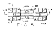
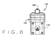
図3〜図6を参照するように、コンプレッサ装置100の一つの実施態様は、それぞれの吸気行程期間にガス流AまたはBの吸入を可能にする吸気コネクタ106Aと、それぞれの放出行程期間に人工呼吸器(図示せず)を通じて患者にガス流A1またはB1を供給するための送出コネクタ106Bとに流体連絡する第一のコンプレッサヘッド102および第二のコンプレッサヘッド104を含むことができる。図7Aおよび図7Bは、コンプレッサ装置100を通るさまざまな流れ経路を図示し、第一のコンプレッサヘッド102および第二のコンプレッサヘッド104が、工程の完全サイクルの完了期間に交互に吸気行程と放出行程とにおいて動作する。図7Aに示すコンプレッサ装置100によって始められる工程の第一の半サイクルにおいて、第一のコンプレッサヘッド102が、それぞれの吸気行程期間にガス流Aを吸引して第一のコンプレッサヘッド102内に送り、一方で同時に、第二のコンプレッサヘッド104が送出コネクタ107を通じてガス流B1を放出し、ガス流B2で指定されるガス流B1の一部を、それぞれの放出行程期間に往復バイパスコンポーネント108を通じて第一のコンプレッサヘッド102に方向転換する。反対に、工程の第二の半サイクル期間に、図7Bに示すコンプレッサ装置100によって、第一のコンプレッサヘッド102が、それぞれの放出行程期間に送出コネクタ106を通じてガス流Aを放出し、一方で同時に、ガス流A2で指定されるガス流の一部A1を、方向転換したガス流B2が取るのとは反対方向に往復バイパスコンポーネント108を通じて第二のコンプレッサヘッド104に方向転換し、同時に第二のコンプレッサヘッド104がそれぞれの吸気行程期間にガス流Bを吸引する。そのようなものとして、第一のコンプレッサヘッド102および第二のコンプレッサヘッド104が交互にそれぞれのガス流AまたはBを吸引し、その後往復バイパスコンポーネント108または送出コネクタ107を通じて交互の方法でそれぞれのガス流A1、A2またはB1、B2を送り出し、それぞれ、吸気行程および放出行程を完了すると、コンプレッサ装置100は工程の完全サイクルを完了する。
As shown in FIGS. 3-6, one embodiment of the
図8を参照し、コンプレッサ装置100の構造要素およびそれらの動作をより詳細に論じる。一つの実施態様では、第一のコンプレッサヘッド102の構造および動作は、第一のコンプレッサヘッド102が第二のコンプレッサヘッド104に対して交互の順序で動作してコンプレッサ装置100における工程の完全サイクルを完了することを除いては、第二のコンプレッサヘッド104に実質的に類似する。第一のコンプレッサヘッド102および第二のコンプレッサヘッド104を動作させるためのモータ116が提供される。とりわけ、モータ116は、第一のコンプレッサヘッド102を動作させるための第一の回転可能なシャフト144と、第二のコンプレッサヘッド104を動作させるための第二の回転可能なシャフト146とを含む。
With reference to FIG. 8, the structural elements of the
示すように、第一のコンプレッサヘッド102は、偏心質量130Aおよび釣り合いおもり132Aがその内部にはめ込まれた連接棒128Aの配置を有するチャンバ134Aを画定するポンプケーシング124Aを含む。連接棒128Aの底部には偏心質量130Aおよび釣り合いおもり132Aがはめ込まれ、一方、連接棒128Aの上部には、位置決めねじ162Aによって弾性ダイヤフラム126Aがはめ込まれる。その上、連接棒128Aの底部には、連接棒128Aを偏心運動において動かすための、モータ116の回転可能なシャフト144がはめ込まれる。動作中、モータ116による連接棒128Aの偏心運動によって、ダイヤフラム126Aが往復運動で動く。アダプタプレート136Aが、モータ116の一端とポンプケーシング124Aとをはめ込むことができる。
As shown, the
一つの実施態様では、ポンプケーシング124の上部にはコンプレッサヘッドハウジング118Aの底部がはめ込まれ、一方、コンプレッサヘッドハウジング118Aの上部ヘッドにはカバーヘッド138Aがはめ込まれる。コンプレッサヘッドハウジング118Aは、吸気チャンバ110Aと連絡し、ガス流Aをその内部に入れることを可能にする吸気口140Aを含む。吸気チャンバ110Aは、吸気チャンバ110Aからキャビティ112A内へのガスの流入を可能にする複数の一方向吸気弁120Aを通じてキャビティ112Aと流体連絡するが、逆行するガス流が吸気チャンバ110A内に戻ることは阻止する。加えて、キャビティ112Aは、キャビティ112Aから放出チャンバ114A内へのガスの流入を可能にするが複数の一方向放出弁122Aを通じて放出チャンバ122Aと流体連絡するが、逆行するガス流がキャビティ112A内に戻ることは阻止する。キャビティ112Aは、半サイクル期間に、キャビティ112Aから離れるダイヤフラム126Aの運動がガス流を吸気チャンバ110Aからキャビティ112A内に送るように往復ダイヤフラム126Aに合わせて作動し、一方、残りの半サイクル期間に、キャビティ112Aに向かうダイヤフラム126Aの運動によって圧縮ガスがコンプレッサヘッドハウジング118Aの出口142Aを通じて出口コネクタ107から出るように、ガスを圧縮してキャビティ112Aから放出チャンバ114A内に流すように構成される。
In one embodiment, the top of pump casing 124 is fitted with the bottom of
第一のコンプレッサヘッド102と同様に, 第二のコンプレッサヘッド104は、偏心質量130Bおよび釣り合いおもり132Bがその内部にはめ込まれた連接棒128Bの配置を有するチャンバ134Bを画定するポンプケーシング124Bを含む。連接棒128Bの底部には偏心質量130Bおよび釣り合いおもり132Bがはめ込まれ、一方、連接棒128Bの上部には、位置決めねじ162Bによって弾性ダイヤフラム126Bがはめ込まれる。その上、連接棒128Bの底部には、連接棒128Bを偏心運動において動かすための、モータ116の回転可能なシャフト144がはめ込まれる。動作中、モータ116による連接棒128Bの偏心運動によって、ダイヤフラム126Bが往復運動で動く。アダプタプレート136Bが、モータ116の一端とポンプケーシング124Bとをはめ込むことができる。
Similar to the
一つの実施態様では、ポンプケーシング124の上部にはコンプレッサヘッドハウジング118Bの底部がはめ込まれ、一方、コンプレッサヘッドハウジング118Bの上部ヘッドにはカバーヘッド138Aがはめ込まれる。コンプレッサヘッドハウジング118Bは、吸気チャンバ110Bと連絡し、ガス流Bをその内部に入れることを可能にする吸気口140Bを含む。吸気チャンバ110Bは、吸気チャンバ110Bからキャビティ112B内へのガスの流入を可能にする複数の一方向吸気弁120Bを通じてキャビティ112Bと流体連絡するが、逆行するガス流が吸気チャンバ110B内に戻ることは阻止する。加えて、キャビティ112Bは、キャビティ112Bから放出チャンバ114B内へのガスの流入を可能にする複数の一方向放出弁122Bを通じて放出チャンバ122Bと流体連絡するが、逆行するガス流がキャビティ112B内に戻ることは阻止する。キャビティ112Bは、第一の半サイクル期間に、キャビティ112Bから離れるダイヤフラム126Bの運動がガス流を吸気チャンバ110Bからキャビティ112B内に送るように往復ダイヤフラム126Bに合わせて作動し、一方、第二の半サイクル期間に、キャビティ112Bに向かうダイヤフラム126Bの運動によって圧縮ガスがコンプレッサヘッドハウジング118Bの出口142Bを通じて出口コネクタ106Bから出るように、ガスを圧縮してキャビティ112Bから放出チャンバ114B内に流すように構成される。
In one embodiment, the top of pump casing 124 is fitted with the bottom of compressor head housing 118B, while the top head of compressor head housing 118B is fitted with
さらに示すように、往復バイパスコンポーネント108は、方向転換したガス流A2および方向転換したガス流B2がコンプレッサヘッド102とコンプレッサヘッド104との間を交互に流れるときに、第一のコンプレッサヘッド102と第二のコンプレッサヘッド104との間に双方向のガス流を流すことができる伸長中空シャフトでもよい。往復バイパスコンポーネント108は、往復バイパスコンポーネント108と第一のコンプレッサヘッド102のカバーヘッド138Aとを連結するためのバイパスフィッティング148Aをはめ込む一端と、往復バイパスコンポーネント108と第二のコンプレッサヘッド104とを連結するための別のバイパスフィッティング148Bをはめ込む反対端とを画定する。シーリング要素158A、例えば、Oリングが、カバーヘッド138Aとバイパスフィッティング148Aとの間の流体密封シールを提供し、一方、シーリング要素158Bが、カバーヘッド138Bとバイパスフィッティング148Bとの間の流体密封シールを提供する。一つの実施態様では、バイパスフィッティング148Bは、バネ154を有するバイパスシート152を通じてソレノイド150に動作可能にはめ込まれる。バネ154は、カバーヘッド138Bによって形成されたオリフィス149を通じる流体連絡を可能にするまたは阻止するためのバイアスを印加する。オリフィス149は、方向転換したガス流A2またはB2に対してオリフィス149を開閉するソレノイド150の作用によってバイパスシート152にはめ込まれるように構成される。そのようなものとして、往復バイパスコンポーネント108の存在によって、コンプレッサ装置100は、バイパスコンポーネント108がない従来のコンプレッサ装置10によって達成可能な流量と比較して、極端に低くかつより安定した流量を達成することが可能になる。
As further shown, the
動作中、ソレノイド150は、第一のコンプレッサヘッド102の放出行程期間にバイパスシート152を開放し、工程の第一の半サイクル期間に、方向転換したガス流A2を第一のコンプレッサヘッド102から第二のコンプレッサヘッド104に流す。同様に、ソレノイド150は、第二のコンプレッサヘッド104の放出行程期間にバイパスシート152を開放し、工程の第二の半サイクル期間に、方向転換したガス流B2を第二のコンプレッサヘッド104から第一のコンプレッサヘッド102に流し、コンプレッサ装置100による工程の完全サイクルを完了することを可能にする。一部のコンポーネントでは、往復バイパスコンポーネント108のオリフィスサイズを調整することによって、第一のコンプレッサヘッド102および第二のコンプレッサヘッド104の各々から特定量のガス流を方向転換し、コンプレッサ装置100による特定の流量を達成することができる。他の実施態様では、往復バイパスコンポーネント108は、可変オリフィス(図示せず)を含むことができる。これが有する可変サイズの開口が、往復バイパスコンポーネント108を通じて他方のコンプレッサヘッド102または104に流れることが可能な方向転換するガス流A2またはB2の程度を変えて、流量調節能力をもたらす。このように、方向転換するガス流A2およびB2の量を調節してコンプレッサ装置100による異なる程度の低流量を達成することができる。
During operation, the
一部の実施態様では、往復バイパスコンポーネント108は、ソレノイド150の代わりにオリフィス149を開放するのに用いることができるスクリュードライバまたは回転型アクチュエータでもよい。
In some implementations, the
往復バイパスコンポーネント108をコンプレッサ装置100に組み込むことの利点は、コンプレッサ装置100の工程の一つの完全サイクルが完了するときに、ガス流の一部をその放出サイクル期間に一つのコンプレッサヘッドから、その吸気サイクル期間に他方のコンプレッサヘッドに方向転換、そして逆もまた同様に方向転換することによって、コンプレッサ装置100によって達成可能な潜在的な定常流を低くすることにある。例として、往復バイパスコンポーネント108を持つコンプレッサ装置100は、(コンプレッサ装置100の能力の毎分80リットル以上に基づいて)放出されるガス流の約97%が他方のコンプレッサヘッドに方向転換、そして逆もまた同様に方向転換するときに、極端に低い流量、例えば、毎分0.1リットルを達成できる。この結果、最大流量と最小流量との比が800対1になる。さまざまな能力を持つ他方のコンプレッサに同じバイパス機能を適用することによって、より高いまたはより低いバイパス流量を達成することができる。
The advantage of incorporating the
一部の実施態様では、補修部品市場での変更として、往復バイパスコンポーネント108を、固定動力源を持つモータを有するコンプレッサ装置100に組み込むことができる。これは、往復バイパスコンポーネント108を通じて方向転換することができるガス流の量を変えることによってコンプレッサ装置における流量調節を達成する手段として用いることができる。
In some implementations, as a change in the repair parts market, the
図9を参照し、コンプレッサ装置100を用いる一つの方法を図示するフローチャートを示す。ブロック200において、送出コネクタ106を通じて第二のコンプレッサヘッド104と流体連絡する第一のコンプレッサヘッド102を有するコンプレッサ装置100を提供し、その後往復バイパスコンポーネント108を第一のコンプレッサヘッド102および第二のコンプレッサヘッド104に流体連絡するようにはめ込む。ブロック202において、ガス流を第一のコンプレッサヘッド102と第二のコンプレッサヘッド104に供給するためにコンプレッサ装置100を人工呼吸器システムにはめ込む。ブロック204において、第一のコンプレッサヘッド102が、第一のコンプレッサヘッド102の第一の放出行程期間に第一のガス流を生成し、第二のコンプレッサヘッド104が、第二のコンプレッサヘッド104の上の期間と交互の第二の放出行程期間に第二のガス流を生成するように、コンプレッサ装置100を作動させる。ブロック206において、第一のガス流の一部を、第一のコンプレッサヘッド102の第一の放出行程期間に第一のコンプレッサヘッド102から往復バイパスコンポーネント108を通じて第二のコンプレッサヘッド104内に流し、その後、交互の第二のガス流の一部を、第二のコンプレッサヘッド104の上の交互の第二の放出行程期間に第二のコンプレッサヘッド104から往復バイパスコンポーネント108を通じて第一のコンプレッサヘッド102内に流す。
Referring to FIG. 9, a flowchart illustrating one method of using the
図10を参照し、コンプレッサ装置100を製造する一つの方法を例示するフローチャートを示す。ブロック300において、第一のコンプレッサヘッド102を、送出コネクタ106を通じて第二のコンプレッサヘッド104にはめ込み、交互の順序で第一のコンプレッサヘッド102および第二のコンプレッサヘッド104からガス流を放出する。ブロック302において、第一のコンプレッサヘッド102と第二のコンプレッサヘッド104との間に往復バイパスコンポーネント108をはめ込んで第一のコンプレッサヘッド102と第二のコンプレッサヘッド104との間の流体連絡を構築し、第一のコンプレッサヘッド102または第二のコンプレッサヘッド104のいずれかから放出されたガス流の一部を、他方のそれぞれのコンプレッサヘッド102または104に方向転換することを可能にする。これによりコンプレッサ装置100は、さもなければ往復バイパスコンポーネント108がないコンプレッサ装置10に必要となるであろうよりも少ない電力を用いて極めて低いかつ安定した流量を達成できる。ブロック304において、第一のコン10LPMプレッサヘッド102および第二のコンプレッサヘッド104を交互の順序で駆動するためのモータ116を第一のコンプレッサヘッド102および第二のコンプレッサヘッド104に動作可能にはめ込む。
Referring to FIG. 10, a flowchart illustrating one method of manufacturing the
往復バイパスコンポーネント108を持つコンプレッサ装置100は、本明細書に記述する医療分野以外の用途を有し得る。例として、コンプレッサ装置100は、暖房および空調の用途のほかに、マルチスピードコンプレッサが一般に用いられる冷凍産業にも用いることができる。
The
テスト結果
往復バイパスコンポーネント108がない先行技術の標準的なコンプレッサ装置10と比較した、往復バイパスコンポーネント108を持つコンプレッサ装置100の優れた性能を実証するために2つの異なるテストを行った。第一のテストは、コンプレッサ装置100と、それと比較する標準的なコンプレッサ装置10とによって示された最小流量と最大流量とを比較した。第二のテストは、標準的なコンプレッサ装置10と往復バイパスコンポーネント108を持つコンプレッサ装置100との間の流量の差異を比較した。第一のテストに関しては、以下の表1〜表5に、往復バイパスコンポーネント108を持つコンプレッサ装置100(表5)と、往復バイパスコンポーネント108がない4つの先行技術の標準的なコンプレッサ装置10(表1〜表4)とによって達成された最大流量と最小流量とを比較したテスト結果を与える。示すように、表1は、製品名GAST 15Dに基づいて製造された往復バイパスコンポーネント108がない標準的なコンプレッサ装置10の結果を表し、2ボルトの電圧設定において毎分0.2リットルの最小流量を示し、12ボルトの電圧設定において毎分17.1リットルの最大流量を示す。

表2は、製品名T−Squaredに基づいて製造された往復バイパスコンポーネント108がない別の標準的なコンプレッサ装置10の結果を表し、1ボルトの電圧設定において毎分5.1リットルの最小流量を示し、12ボルトの電圧設定において毎分82.3リットルの最大流量を示す。表3は、製品名KNFに基づいて製造された往復バイパスコンポーネント108がない別の標準的なコンプレッサ装置10の結果を表し、1ボルトの電圧設定において毎分31.1リットルの最小流量を示し、8ボルトの電圧設定において毎分73.8リットルの最大流量を示す。表4は、製品名Powerexに基づいて製造された往復バイパスコンポーネント108がないなおも別の標準的なコンプレッサ装置10の結果を表し、1.7ボルトの電圧設定において毎分1.3リットルの最小流量を示す。最後に、表5は、当発明者によって製造された往復バイパスコンポーネント108を持つコンプレッサ装置100の結果を表し、往復バイパスコンポーネント108が動作可能であるときの1ボルトの電圧設定において毎分0.1リットルの最小流量を示し、12ボルトの電圧設定において毎分48.1リットルの最大流量を示す。一方、コンプレッサ装置100は、往復バイパスコンポーネント108が非動作であるときは、1ボルトの電圧設定において毎分3.1リットルの最小流量を示し、毎分83.5リットルの最大流量を示す。先に述べたように、往復バイパスコンポーネント108を持つコンプレッサ装置100は、任意の極端に低い流量を達成するように時には往復バイパスコンポーネント108を動作可能にし、一方、極端に高い流量を達成するように時には往復バイパスコンポーネント108を非動作状態にするように動作することができる。表6は、往復バイパスコンポーネント108を有するコンプレッサ装置100と比較した、往復バイパスコンポーネント108がない前述のコンプレッサ装置10の各々における最小流量、最大流量および送出流量比(最大流量/最小流量)を示す。
表6に示すように、往復バイパスコンポーネント108を持つコンプレッサ装置100の流量比は、往復バイパスコンポーネント108がない標準的なコンプレッサ装置10の最も近い流量比のほぼ10倍である。例として、表1の往復バイパスコンポーネント108がないGAST 15Dコンプレッサ装置10の流量比は、85.5対1であり、表2の往復バイパスコンポーネント108がないT−Squaredコンプレッサ装置10の流量比は、16.1対1であり、表3の往復バイパスコンポーネント108がないKNFコンプレッサ装置10の流量比は、2.4対1であり、そして表4の往復バイパスコンポーネント108がないPowerexコンプレッサ装置10の流量比は、61.0対1である。対照的に、往復バイパスコンポーネント108が動作可能であるときのコンプレッサ装置100の流量比は481対1であるが、毎分0.1リットルの低流量を達成するための動作モードと、図5に例証するような毎分83.5リットルの大流量を達成するための非動作モードとに、コンプレッサ装置100が往復バイパスコンポーネント108を切り替える場合には、836対1のより高い流量比でさえ達成することができる。テスト結果は、往復バイパスコンポーネント108を持つコンプレッサ装置100が遥かに大きな最大流量と最小流量との比を有することを明確に示す。その結果、同様の動作条件下で、バイパスコンポーネント108がない先行技術の標準的なコンプレッサ装置10によって達成可能な流量よりも極めて大きな範囲の流量を示す。KNFおよびPowerexコンプレッサ装置10の電圧設定は、それぞれ、テスト期間に他のコンプレッサ装置10およびコンプレッサ装置100に用いられる1〜12ボルトの通常の電圧設定範囲ではなく、1〜8ボルトおよび1.7〜4.6ボルトである。しかしながら、KNFおよびPowerexコンプレッサ装置10におけるこれらのより小さい電圧設定範囲が、同程度の最小流量および最大流量の両方を得るための、同等の完全動作が可能な範囲においてこれらの特定のコンプレッサ装置10を動作させるよりも小さい動作電圧設定に起因することに留意すべきである。
As shown in Table 6, the flow rate ratio of the
表7は、毎分10リットルの同じ流量において、往復バイパスコンポーネント108を有するコンプレッサ装置100と、標準的なコンプレッサ装置10とを比較した、脈動と呼ばれる流量の差異を比較するための第二のテストの結果を示す。特定の流量を維持する場合にコンプレッサ装置による流量脈動または流量の差異を最小化することが重要である。なぜならば、特定の流量を維持する場合にコンプレッサ装置が流量に高い差異を示す場合に、人工呼吸器に接続された患者が大きな流量の差異を感じ得るからである。図11に図示するグラフ、および表7の2つのタイプのコンプレッサ装置10および100間のテスト結果は、往復バイパスコンポーネント108を持つコンプレッサ装置100が、同じ毎分10リットルの流量を維持するときの往復バイパスコンポーネント108がない標準的なコンプレッサ装置10よりも、毎分10リットルの流量を維持するときに極めて低い流量の差異を実証することを明確に示す。示すように、往復バイパスコンポーネント108がない標準的なコンプレッサ装置10によって示される、毎分10リットルの流量を維持するときの流量の差異は、毎分約4.7リットルであり、一方、往復バイパスコンポーネント108を持つコンプレッサ装置100によって示される、同じ毎分10リットルの流量を維持するときの流量の差異は、毎分約2.0リットルである。そのようなものとして、往復バイパスコンポーネント108がない標準的なコンプレッサ装置10は、往復バイパスコンポーネント108を持つコンプレッサ装置100における流量の差異よりも約2.5倍大きい流量の差異を示す。図11のグラフに例証するテストデータを示す表7を以下に示す。
特定の実施態様を図示し、記述したが、当業者に明らかなように、本発明の精神および範囲から逸することなく、それらにさまざまな変更を為せることが前の記述から理解されるべきである。そのような変化および変更は、これに添付される請求項に定義されるように本発明の範囲内および教示内にある。 While particular embodiments have been illustrated and described, it should be understood from the foregoing description that it will be apparent to those skilled in the art that various modifications can be made thereto without departing from the spirit and scope of the invention. It is. Such changes and modifications are within the scope and teachings of the invention as defined in the claims appended hereto.
Claims (20)
前記第一のコンプレッサヘッド(102)と流体連絡し、第二のガス流を生成するための第二のコンプレッサヘッド(104)と、
前記第一のコンプレッサヘッド(102)および前記第二のコンプレッサヘッド(104)と流体連絡し、前記第一のコンプレッサヘッド(102)および前記第二のコンプレッサヘッド(104)による、それぞれ、前記第一のガス流および前記第二のガス流の連続的な交互の送出を可能にするための送出コネクタ(106)と、
前記第一のコンプレッサヘッド(102)および前記第二のコンプレッサヘッド(104)と流体連絡し、前記第一のコンプレッサヘッド(102)と前記第二のコンプレッサヘッド(104)との交互のガス流の送出を可能にする往復バイパスコンポーネント(108)であって、これにより交互の順序で、前記第一のガス流の一部が前記第一のコンプレッサヘッド(102)から前記第二のコンプレッサヘッド(104)に方向転換し、第二のガス流の一部が前記第二のコンプレッサヘッド(104)から前記第一のコンプレッサヘッド(102)に方向転換する、往復バイパスコンポーネント(108)と
を備える、コンプレッサ装置(100)。 A first compressor head (102) for generating a first gas stream;
A second compressor head (104) in fluid communication with the first compressor head (102) for generating a second gas stream;
The first compressor head (102) and the second compressor head (104) are in fluid communication with the first compressor head (102) and the second compressor head (104), respectively. A delivery connector (106) for enabling continuous alternating delivery of the second gas stream and the second gas stream;
Fluid communication with the first compressor head (102) and the second compressor head (104), and the alternating flow of gas between the first compressor head (102) and the second compressor head (104). A reciprocating bypass component (108) that enables delivery, whereby, in an alternating sequence, a portion of the first gas stream is transferred from the first compressor head (102) to the second compressor head (104). And a reciprocating bypass component (108) in which a portion of the second gas stream is diverted from the second compressor head (104) to the first compressor head (102). Device (100).
吸気チャンバ(110A、110B)と流体連絡し、その中への前記ガス流の吸入を可能にするための吸気ポート(140A、140B)と、
前記吸気チャンバ(110A、110B)およびキャビティ(112A、112B)と連絡し、それぞれの第一の吸気行程および第二の吸気行程期間に、前記ガス流を前記吸気チャンバ(110A、110B)から、前記キャビティ(112A、112B)内に流すための少なくとも一つの吸気弁(120A、120B)と、
前記キャビティ(112A、112B)および放出チャンバ(114A、114B)と連絡し、それぞれの第一の放出行程および第二の放出行程期間に、前記ガス流を前記キャビティ(112A、112B)から、前記放出チャンバ(114A、114B)内に流すための少なくとも一つの放出弁(122A、122B)と、
前記それぞれの第一の吸気行程または第二の吸気行程期間に、前記キャビティ(112A、112B)に対して往復運動で駆動し、弾性ダイヤフラム(126A、126B)の一つの運動によって前記ガス流を前記キャビティ(112A、112B)内に吸引し、前記それぞれの第一の放出行程または第二の放出行程期間に、前記弾性ダイヤフラム(126A、126B)の反対運動によってガスを前記キャビティ(112A、112B)から外に出すように構成された弾性ダイヤフラム(126A、126B)と、
前記放出チャンバ(114A、114B)と流体連絡し、前記それぞれの第一の放出行程および第二の放出行程期間に、前記ガス流を前記放出チャンバ(114A、114B)から出すための出口ポート(142A、142B)と
を備える、請求項4記載のコンプレッサ装置(100)。 Each of the first compressor head (102) and the second compressor head (104)
An intake port (140A, 140B) for fluid communication with the intake chamber (110A, 110B) and allowing the inhalation of the gas flow into it;
In communication with the intake chamber (110A, 110B) and cavity (112A, 112B), the gas flow from the intake chamber (110A, 110B) during the first and second intake strokes, respectively, At least one intake valve (120A, 120B) for flowing into the cavities (112A, 112B);
In communication with the cavities (112A, 112B) and discharge chambers (114A, 114B), the gas flow from the cavities (112A, 112B) during the first discharge stroke and second discharge stroke, respectively. At least one discharge valve (122A, 122B) for flow into the chamber (114A, 114B);
During the respective first intake stroke or second intake stroke period, the cavity (112A, 112B) is driven in a reciprocating motion, and the gas flow is changed by one movement of an elastic diaphragm (126A, 126B). Gas is sucked into the cavities (112A, 112B) and gas is released from the cavities (112A, 112B) by the opposite movement of the elastic diaphragms (126A, 126B) during the respective first discharge stroke or second discharge stroke. An elastic diaphragm (126A, 126B) configured to go out;
An outlet port (142A) for fluid communication with the discharge chamber (114A, 114B) and for exiting the gas stream from the discharge chamber (114A, 114B) during the respective first and second discharge strokes. 142B). Compressor apparatus (100) according to claim 4, comprising:
第一のガス流を生成するための第一のコンプレッサヘッド(102)と、
前記第一のコンプレッサヘッド(102)と流体連絡し、第二のガス流を生成するための第二のコンプレッサヘッド(104)と、
前記第一のコンプレッサヘッド(102)および前記第二のコンプレッサヘッド(104)と流体連絡し、前記第一のコンプレッサヘッド(102)および前記第二のコンプレッサヘッド(104)によるガス流の連続的な交互の送出を可能にするための送出コネクタ(106)と、
前記第一のコンプレッサヘッド(102)および前記第二のコンプレッサヘッド(104)と流体連絡する往復バイパスコンポーネント(108)で、そこを通じて前記第一のコンプレッサヘッド(102)と前記第二のコンプレッサヘッド(104)との交互のガス流の送出を可能にする往復バイパスコンポーネント(108)であって、これにより交互の順序で、前記第一のガス流の一部が前記第一のコンプレッサヘッド(102)から前記第二のコンプレッサヘッド(104)に方向転換し、前記第二のガス流の一部が前記第二のコンプレッサヘッド(104)から前記第一のコンプレッサヘッド(102)に方向転換する、往復バイパスコンポーネント(108)と
を備えたコンプレッサ装置(100)を提供することと、
前記第一のガス流の一部を前記第一のコンプレッサヘッド(102)から前記往復バイパスコンポーネント(108)を通じて前記第二のコンプレッサヘッド(104)に方向転換することと、
前記第二のガス流の一部を前記第二のコンプレッサヘッド(104)から前記往復バイパスコンポーネント(108)を通じて前記第一のコンプレッサヘッド(102)に方向転換し、交互の順序で、前記第一のガス流の一部を前記第一のコンプレッサヘッド(102)から前記第二のコンプレッサヘッド(104)に方向転換することと
を含む、方法。 A method for using a compressor device (100) comprising:
A first compressor head (102) for generating a first gas stream;
A second compressor head (104) in fluid communication with the first compressor head (102) for generating a second gas stream;
Fluid communication with the first compressor head (102) and the second compressor head (104), and the continuous flow of gas by the first compressor head (102) and the second compressor head (104) A delivery connector (106) for enabling alternate delivery;
A reciprocating bypass component (108) in fluid communication with the first compressor head (102) and the second compressor head (104), through which the first compressor head (102) and the second compressor head ( 104) a reciprocating bypass component (108) that allows delivery of alternating gas streams with the first compressor stream (102), wherein a portion of the first gas stream is in alternating order. Reciprocating from the second compressor head (104) to the second compressor head (104) and a portion of the second gas flow from the second compressor head (104) to the first compressor head (102). Providing a compressor device (100) with a bypass component (108);
Redirecting a portion of the first gas stream from the first compressor head (102) through the reciprocating bypass component (108) to the second compressor head (104);
A portion of the second gas stream is diverted from the second compressor head (104) through the reciprocating bypass component (108) to the first compressor head (102) and in an alternating order, the first Redirecting a portion of the gas flow from the first compressor head (102) to the second compressor head (104).
前記第一のコンプレッサヘッド(102)と前記第二のコンプレッサヘッド(104)との間に往復バイパスコンポーネント(108)をはめ込んで、前記第一のコンプレッサヘッド(102)と前記第二のコンプレッサヘッド(104)との間の流体連絡を構築し、交互の順序で、前記送出された第一のガス流の一部を前記第一のコンプレッサヘッド(102)から前記第二のコンプレッサヘッド(104)に流し、前記送出された第二のガス流の一部を前記第二のコンプレッサヘッド(104)から前記第一のコンプレッサヘッド(102)に流すことと、
前記第一のコンプレッサヘッド(102)および前記第二のコンプレッサヘッド(104)を交互の順序で駆動させるためのモータ(116)を前記第一のコンプレッサヘッド(102)および前記第二のコンプレッサヘッド(104)に動作可能にはめ込むことと
を含む、コンプレッサ装置(100)を製造する方法。 The first compressor head (102) is fitted with the delivery connector (106) into the second compressor head (104) to deliver the first gas stream from the first compressor head (102) in an alternating sequence. Enabling delivery of a second gas stream from the second compressor head (104);
A reciprocating bypass component (108) is fitted between the first compressor head (102) and the second compressor head (104) so that the first compressor head (102) and the second compressor head ( 104) and, in an alternating sequence, a portion of the delivered first gas stream is transferred from the first compressor head (102) to the second compressor head (104). Flowing a portion of the delivered second gas stream from the second compressor head (104) to the first compressor head (102);
A motor (116) for driving the first compressor head (102) and the second compressor head (104) in an alternating sequence is connected to the first compressor head (102) and the second compressor head ( 104) operably engaging the method of manufacturing the compressor apparatus (100).
Applications Claiming Priority (3)
| Application Number | Priority Date | Filing Date | Title |
|---|---|---|---|
| US13/229,133 | 2011-09-09 | ||
| US13/229,133 US9022746B2 (en) | 2011-09-09 | 2011-09-09 | Shuttling by-pass compressor apparatus |
| PCT/US2012/049715 WO2013036339A1 (en) | 2011-09-09 | 2012-08-06 | Shuttling by-pass compressor apparatus |
Publications (3)
| Publication Number | Publication Date |
|---|---|
| JP2014526308A JP2014526308A (en) | 2014-10-06 |
| JP2014526308A5 JP2014526308A5 (en) | 2015-09-24 |
| JP6055475B2 true JP6055475B2 (en) | 2016-12-27 |
Family
ID=47829991
Family Applications (1)
| Application Number | Title | Priority Date | Filing Date |
|---|---|---|---|
| JP2014529720A Active JP6055475B2 (en) | 2011-09-09 | 2012-08-06 | Reciprocating bypass compressor device |
Country Status (11)
| Country | Link |
|---|---|
| US (1) | US9022746B2 (en) |
| EP (1) | EP2753391B1 (en) |
| JP (1) | JP6055475B2 (en) |
| AU (1) | AU2012304846B2 (en) |
| BR (1) | BR112014005481B1 (en) |
| CA (1) | CA2846166C (en) |
| ES (1) | ES2617493T3 (en) |
| HK (1) | HK1199850A1 (en) |
| MX (1) | MX341725B (en) |
| RU (1) | RU2593360C2 (en) |
| WO (1) | WO2013036339A1 (en) |
Families Citing this family (4)
| Publication number | Priority date | Publication date | Assignee | Title |
|---|---|---|---|---|
| TWI683960B (en) * | 2017-09-15 | 2020-02-01 | 研能科技股份有限公司 | Gas transmitting device |
| US10920758B2 (en) * | 2018-06-29 | 2021-02-16 | Bendix Commercial Vehicle Systems Llc | Hypocycloid compressor |
| JP2023552280A (en) * | 2020-11-09 | 2023-12-15 | ピーディーシー マシンズ インク. | Active oil injection system for diaphragm compressors |
| WO2023215485A1 (en) * | 2022-05-04 | 2023-11-09 | Haptx, Inc. | Haptic glove system and manufacture of haptic glove systems |
Family Cites Families (22)
| Publication number | Priority date | Publication date | Assignee | Title |
|---|---|---|---|---|
| US2285215A (en) * | 1939-06-08 | 1942-06-02 | Binks Mfg Co | Fluid compressor |
| GB914343A (en) | 1959-02-06 | 1963-01-02 | Pye Ltd | Electronic time cycled respirator |
| US3101768A (en) * | 1960-09-15 | 1963-08-27 | Curtis Automotive Devices Inc | Resonant intermittent combustion devices |
| DE1453646A1 (en) * | 1964-05-22 | 1969-11-13 | Rau Swf Autozubehoer | Diaphragm pump with built-in electric motor |
| DE2158458A1 (en) * | 1971-11-25 | 1973-05-30 | Langen & Co | AUTOMATIC VENTING DEVICE |
| US4778356A (en) * | 1985-06-11 | 1988-10-18 | Hicks Cecil T | Diaphragm pump |
| US4842498A (en) * | 1987-01-20 | 1989-06-27 | Thomas Industries, Inc. | Diaphragm compressor |
| US4813979A (en) * | 1988-02-02 | 1989-03-21 | The United States Of America As Represented By The Secretary Of The Air Force | Secondary oxygen purifier for molecular sieve oxygen concentrator |
| DE3919667A1 (en) * | 1989-06-16 | 1990-12-20 | Schneider Druckluft Gmbh | Control system for double compressor unit - has arrangement to vary main load on alternate basis |
| DE9317083U1 (en) * | 1993-11-09 | 1994-01-13 | Knf Neuberger Gmbh | Pump with a drive motor and a housing |
| FR2733688B1 (en) * | 1995-05-05 | 1997-09-05 | Saime Sarl | BREATHING ASSISTANCE APPARATUS OF WHICH THE GAS FLOW SOURCE IS A MEMBRANE COMPRESSOR WITH ELECTROMAGNETIC ACTUATION |
| US6062256A (en) * | 1997-02-11 | 2000-05-16 | Engineering Measurements Company | Micro mass flow control apparatus and method |
| US6126410A (en) * | 1998-02-12 | 2000-10-03 | Gast Manufacturing Corporation | Head cover assembly for reciprocating compressor |
| US5968236A (en) * | 1998-02-20 | 1999-10-19 | Bassine; Stuart | Valve free oxygen concentrator |
| RU2146536C1 (en) * | 1999-04-16 | 2000-03-20 | Специальное конструкторское бюро экспериментального оборудования при Государственном научном центре Российской Федерации "Институт медико-биологических проблем" | Method for preparation and supply of therapeutic gas mix and device for its embodiment |
| US7320321B2 (en) | 2002-08-26 | 2008-01-22 | Automedx Inc. | Self-contained micromechanical ventilator |
| US7134849B1 (en) * | 2003-04-22 | 2006-11-14 | Trebor International, Inc. | Molded disposable pneumatic pump |
| WO2005092416A1 (en) * | 2004-02-26 | 2005-10-06 | Sekos, Inc. | Self-contained micromechanical ventilator |
| US7517199B2 (en) * | 2004-11-17 | 2009-04-14 | Proportion Air Incorporated | Control system for an air operated diaphragm pump |
| US7686870B1 (en) | 2005-12-29 | 2010-03-30 | Inogen, Inc. | Expandable product rate portable gas fractionalization system |
| WO2008021503A2 (en) * | 2006-08-18 | 2008-02-21 | L*Vad Technology, Inc. | Air supply mechanism for ventricular assist system |
| US20090065007A1 (en) | 2007-09-06 | 2009-03-12 | Wilkinson William R | Oxygen concentrator apparatus and method |
-
2011
- 2011-09-09 US US13/229,133 patent/US9022746B2/en active Active
-
2012
- 2012-08-06 AU AU2012304846A patent/AU2012304846B2/en active Active
- 2012-08-06 MX MX2014002678A patent/MX341725B/en active IP Right Grant
- 2012-08-06 EP EP12830772.5A patent/EP2753391B1/en active Active
- 2012-08-06 BR BR112014005481-9A patent/BR112014005481B1/en active IP Right Grant
- 2012-08-06 RU RU2014113758/14A patent/RU2593360C2/en active
- 2012-08-06 JP JP2014529720A patent/JP6055475B2/en active Active
- 2012-08-06 WO PCT/US2012/049715 patent/WO2013036339A1/en active Application Filing
- 2012-08-06 ES ES12830772.5T patent/ES2617493T3/en active Active
- 2012-08-06 CA CA2846166A patent/CA2846166C/en active Active
-
2015
- 2015-01-14 HK HK15100370.3A patent/HK1199850A1/en unknown
Also Published As
| Publication number | Publication date |
|---|---|
| EP2753391B1 (en) | 2016-12-28 |
| BR112014005481A2 (en) | 2017-03-21 |
| BR112014005481B1 (en) | 2020-12-08 |
| WO2013036339A1 (en) | 2013-03-14 |
| AU2012304846B2 (en) | 2016-10-27 |
| RU2014113758A (en) | 2015-10-20 |
| MX341725B (en) | 2016-08-31 |
| JP2014526308A (en) | 2014-10-06 |
| ES2617493T3 (en) | 2017-06-19 |
| US20130064687A1 (en) | 2013-03-14 |
| RU2593360C2 (en) | 2016-08-10 |
| US9022746B2 (en) | 2015-05-05 |
| AU2012304846A1 (en) | 2014-03-06 |
| HK1199850A1 (en) | 2015-07-24 |
| CA2846166C (en) | 2019-06-04 |
| MX2014002678A (en) | 2014-04-25 |
| EP2753391A1 (en) | 2014-07-16 |
| EP2753391A4 (en) | 2015-07-29 |
| CA2846166A1 (en) | 2013-03-14 |
Similar Documents
| Publication | Publication Date | Title |
|---|---|---|
| JP6055475B2 (en) | Reciprocating bypass compressor device | |
| CN104174077B (en) | Pump cassette | |
| CN102808757B (en) | Pump unit, respiratory auxiliary system | |
| JPS63105769A (en) | Method and apparatus for allowing two kinds of liquid for artificial kidney to feed out as continuous flow in same amount by pump | |
| CN100532837C (en) | Compressors for hand held oral care devices | |
| US3658443A (en) | Pressure alternating device for automatic lungs ventilator actuation | |
| CN110496280A (en) | Suction apparatus component and vibrational system | |
| US20050084395A1 (en) | Vacuum driven pump for a lavage instrument | |
| US10688228B2 (en) | Suction device | |
| JP2001082326A (en) | Oil feeding device of linear compressor | |
| KR20200001982A (en) | Liquid supply apparatus and liquid supply method | |
| JP4734519B2 (en) | Reciprocating pump structure with removable pump head | |
| JP2014526308A5 (en) | ||
| CN109996572A (en) | The method of the outer blood pump of external blood pump, heart-lung machine, operating body, and the method for operation heart-lung machine | |
| CN111886042A (en) | Miniature two-way valve and system | |
| JP2014525543A (en) | Multiple valve head compressor unit | |
| JP3595912B2 (en) | Inhaler | |
| JP2014525543A5 (en) | ||
| JP2001073953A (en) | Pump | |
| KR200300043Y1 (en) | Oxygen Concentrator | |
| JPH03111675A (en) | Plunger pump | |
| JP6396274B2 (en) | Liquid supply apparatus and liquid supply method | |
| JPH0286968A (en) | Plunger pump | |
| JP2001115968A (en) | Injector | |
| JPH05265575A (en) | Discharge quantity control method for circulating pump of drug solution and drug solution circulation filter |
Legal Events
| Date | Code | Title | Description |
|---|---|---|---|
| A521 | Request for written amendment filed |
Free format text: JAPANESE INTERMEDIATE CODE: A523 Effective date: 20150803 |
|
| A621 | Written request for application examination |
Free format text: JAPANESE INTERMEDIATE CODE: A621 Effective date: 20150803 |
|
| RD04 | Notification of resignation of power of attorney |
Free format text: JAPANESE INTERMEDIATE CODE: A7424 Effective date: 20160215 |
|
| A977 | Report on retrieval |
Free format text: JAPANESE INTERMEDIATE CODE: A971007 Effective date: 20160415 |
|
| A131 | Notification of reasons for refusal |
Free format text: JAPANESE INTERMEDIATE CODE: A131 Effective date: 20160419 |
|
| A521 | Request for written amendment filed |
Free format text: JAPANESE INTERMEDIATE CODE: A523 Effective date: 20160715 |
|
| TRDD | Decision of grant or rejection written | ||
| A01 | Written decision to grant a patent or to grant a registration (utility model) |
Free format text: JAPANESE INTERMEDIATE CODE: A01 Effective date: 20161122 |
|
| A61 | First payment of annual fees (during grant procedure) |
Free format text: JAPANESE INTERMEDIATE CODE: A61 Effective date: 20161202 |
|
| R150 | Certificate of patent or registration of utility model |
Ref document number: 6055475 Country of ref document: JP Free format text: JAPANESE INTERMEDIATE CODE: R150 |
|
| R250 | Receipt of annual fees |
Free format text: JAPANESE INTERMEDIATE CODE: R250 |
|
| R250 | Receipt of annual fees |
Free format text: JAPANESE INTERMEDIATE CODE: R250 |
|
| R250 | Receipt of annual fees |
Free format text: JAPANESE INTERMEDIATE CODE: R250 |
|
| R250 | Receipt of annual fees |
Free format text: JAPANESE INTERMEDIATE CODE: R250 |
|
| R250 | Receipt of annual fees |
Free format text: JAPANESE INTERMEDIATE CODE: R250 |