JP6054990B2 - Batch charger with removable head for submerged batch loading - Google Patents
Batch charger with removable head for submerged batch loading Download PDFInfo
- Publication number
- JP6054990B2 JP6054990B2 JP2014560431A JP2014560431A JP6054990B2 JP 6054990 B2 JP6054990 B2 JP 6054990B2 JP 2014560431 A JP2014560431 A JP 2014560431A JP 2014560431 A JP2014560431 A JP 2014560431A JP 6054990 B2 JP6054990 B2 JP 6054990B2
- Authority
- JP
- Japan
- Prior art keywords
- batch
- batch charger
- charger
- slide gate
- furnace
- Prior art date
- Legal status (The legal status is an assumption and is not a legal conclusion. Google has not performed a legal analysis and makes no representation as to the accuracy of the status listed.)
- Active
Links
- 239000000463 material Substances 0.000 claims description 50
- 239000011521 glass Substances 0.000 claims description 39
- 238000002844 melting Methods 0.000 claims description 28
- 230000008018 melting Effects 0.000 claims description 28
- 238000000034 method Methods 0.000 claims description 22
- 239000002826 coolant Substances 0.000 claims description 12
- 238000001816 cooling Methods 0.000 claims description 12
- 239000006060 molten glass Substances 0.000 claims description 11
- 239000000203 mixture Substances 0.000 claims description 5
- 239000012768 molten material Substances 0.000 claims description 3
- 230000000295 complement effect Effects 0.000 claims 1
- 238000003780 insertion Methods 0.000 claims 1
- 230000037431 insertion Effects 0.000 claims 1
- 239000001301 oxygen Substances 0.000 description 10
- 229910052760 oxygen Inorganic materials 0.000 description 10
- QVGXLLKOCUKJST-UHFFFAOYSA-N atomic oxygen Chemical compound [O] QVGXLLKOCUKJST-UHFFFAOYSA-N 0.000 description 9
- 239000000446 fuel Substances 0.000 description 6
- 238000002485 combustion reaction Methods 0.000 description 5
- 239000007789 gas Substances 0.000 description 5
- 239000011368 organic material Substances 0.000 description 5
- VNWKTOKETHGBQD-UHFFFAOYSA-N methane Chemical compound C VNWKTOKETHGBQD-UHFFFAOYSA-N 0.000 description 4
- XLYOFNOQVPJJNP-UHFFFAOYSA-N water Substances O XLYOFNOQVPJJNP-UHFFFAOYSA-N 0.000 description 4
- 239000011230 binding agent Substances 0.000 description 3
- 238000010410 dusting Methods 0.000 description 3
- 239000002557 mineral fiber Substances 0.000 description 3
- 238000000197 pyrolysis Methods 0.000 description 3
- 230000008646 thermal stress Effects 0.000 description 3
- 238000009736 wetting Methods 0.000 description 3
- IJGRMHOSHXDMSA-UHFFFAOYSA-N Atomic nitrogen Chemical compound N#N IJGRMHOSHXDMSA-UHFFFAOYSA-N 0.000 description 2
- 239000000470 constituent Substances 0.000 description 2
- 239000000110 cooling liquid Substances 0.000 description 2
- 239000011261 inert gas Substances 0.000 description 2
- 239000007788 liquid Substances 0.000 description 2
- 239000002184 metal Substances 0.000 description 2
- 239000011490 mineral wool Substances 0.000 description 2
- 239000003345 natural gas Substances 0.000 description 2
- 238000007789 sealing Methods 0.000 description 2
- 239000002028 Biomass Substances 0.000 description 1
- 239000000853 adhesive Substances 0.000 description 1
- 230000001070 adhesive effect Effects 0.000 description 1
- 230000015556 catabolic process Effects 0.000 description 1
- 238000006243 chemical reaction Methods 0.000 description 1
- 238000011437 continuous method Methods 0.000 description 1
- 230000008878 coupling Effects 0.000 description 1
- 238000010168 coupling process Methods 0.000 description 1
- 238000005859 coupling reaction Methods 0.000 description 1
- 238000006731 degradation reaction Methods 0.000 description 1
- 238000000151 deposition Methods 0.000 description 1
- 239000010791 domestic waste Substances 0.000 description 1
- 230000008020 evaporation Effects 0.000 description 1
- 238000001704 evaporation Methods 0.000 description 1
- 238000001125 extrusion Methods 0.000 description 1
- 239000000835 fiber Substances 0.000 description 1
- 239000002657 fibrous material Substances 0.000 description 1
- 239000012634 fragment Substances 0.000 description 1
- 239000011491 glass wool Substances 0.000 description 1
- 238000010438 heat treatment Methods 0.000 description 1
- 238000002347 injection Methods 0.000 description 1
- 239000007924 injection Substances 0.000 description 1
- 238000009413 insulation Methods 0.000 description 1
- 230000007257 malfunction Effects 0.000 description 1
- 238000010309 melting process Methods 0.000 description 1
- 229910052757 nitrogen Inorganic materials 0.000 description 1
- 239000010815 organic waste Substances 0.000 description 1
- 239000007800 oxidant agent Substances 0.000 description 1
- 230000001590 oxidative effect Effects 0.000 description 1
- 150000002926 oxygen Chemical class 0.000 description 1
- 239000000123 paper Substances 0.000 description 1
- 239000002245 particle Substances 0.000 description 1
- 229920005596 polymer binder Polymers 0.000 description 1
- 239000002491 polymer binding agent Substances 0.000 description 1
- 230000002028 premature Effects 0.000 description 1
- 230000001681 protective effect Effects 0.000 description 1
- 238000010926 purge Methods 0.000 description 1
- 239000010819 recyclable waste Substances 0.000 description 1
- 238000004064 recycling Methods 0.000 description 1
- 239000011343 solid material Substances 0.000 description 1
- 239000004449 solid propellant Substances 0.000 description 1
- 239000000126 substance Substances 0.000 description 1
- 238000011144 upstream manufacturing Methods 0.000 description 1
Images


Classifications
-
- C—CHEMISTRY; METALLURGY
- C03—GLASS; MINERAL OR SLAG WOOL
- C03B—MANUFACTURE, SHAPING, OR SUPPLEMENTARY PROCESSES
- C03B3/00—Charging the melting furnaces
- C03B3/005—Charging the melting furnaces using screw feeders
-
- C—CHEMISTRY; METALLURGY
- C03—GLASS; MINERAL OR SLAG WOOL
- C03B—MANUFACTURE, SHAPING, OR SUPPLEMENTARY PROCESSES
- C03B3/00—Charging the melting furnaces
-
- C—CHEMISTRY; METALLURGY
- C03—GLASS; MINERAL OR SLAG WOOL
- C03B—MANUFACTURE, SHAPING, OR SUPPLEMENTARY PROCESSES
- C03B5/00—Melting in furnaces; Furnaces so far as specially adapted for glass manufacture
- C03B5/005—Melting in furnaces; Furnaces so far as specially adapted for glass manufacture of glass-forming waste materials
-
- C—CHEMISTRY; METALLURGY
- C03—GLASS; MINERAL OR SLAG WOOL
- C03B—MANUFACTURE, SHAPING, OR SUPPLEMENTARY PROCESSES
- C03B5/00—Melting in furnaces; Furnaces so far as specially adapted for glass manufacture
- C03B5/16—Special features of the melting process; Auxiliary means specially adapted for glass-melting furnaces
- C03B5/235—Heating the glass
- C03B5/2353—Heating the glass by combustion with pure oxygen or oxygen-enriched air, e.g. using oxy-fuel burners or oxygen lances
-
- C—CHEMISTRY; METALLURGY
- C03—GLASS; MINERAL OR SLAG WOOL
- C03B—MANUFACTURE, SHAPING, OR SUPPLEMENTARY PROCESSES
- C03B5/00—Melting in furnaces; Furnaces so far as specially adapted for glass manufacture
- C03B5/16—Special features of the melting process; Auxiliary means specially adapted for glass-melting furnaces
- C03B5/235—Heating the glass
- C03B5/2356—Submerged heating, e.g. by using heat pipes, hot gas or submerged combustion burners
-
- F—MECHANICAL ENGINEERING; LIGHTING; HEATING; WEAPONS; BLASTING
- F27—FURNACES; KILNS; OVENS; RETORTS
- F27D—DETAILS OR ACCESSORIES OF FURNACES, KILNS, OVENS, OR RETORTS, IN SO FAR AS THEY ARE OF KINDS OCCURRING IN MORE THAN ONE KIND OF FURNACE
- F27D3/00—Charging; Discharging; Manipulation of charge
- F27D3/08—Screw feeders; Screw dischargers
-
- Y—GENERAL TAGGING OF NEW TECHNOLOGICAL DEVELOPMENTS; GENERAL TAGGING OF CROSS-SECTIONAL TECHNOLOGIES SPANNING OVER SEVERAL SECTIONS OF THE IPC; TECHNICAL SUBJECTS COVERED BY FORMER USPC CROSS-REFERENCE ART COLLECTIONS [XRACs] AND DIGESTS
- Y02—TECHNOLOGIES OR APPLICATIONS FOR MITIGATION OR ADAPTATION AGAINST CLIMATE CHANGE
- Y02P—CLIMATE CHANGE MITIGATION TECHNOLOGIES IN THE PRODUCTION OR PROCESSING OF GOODS
- Y02P40/00—Technologies relating to the processing of minerals
- Y02P40/50—Glass production, e.g. reusing waste heat during processing or shaping
Description
本発明は、取外し可能なスライドゲートダンパーによって形成された頭部を含むバッチ材料チャージャー(charger)、このようなバッチチャージャー(batch charger)を含むガラス溶融設備、およびこのような設備を使用するガラス溶融方法に関する。 The present invention relates to a batch material charger including a head formed by a removable slide gate damper, a glass melting facility including such a batch charger, and glass melting using such a facility. Regarding the method.
ガラス炉において、バッチ材料の投入(charging)は従来、ガラス浴上にこれらの材料を堆積させることによって達成されている。ガラスのレベル(液面)より上に位置する従来のバーナーを伴う炉においては、バッチ材料が高温の炉ガスにより運び去られるのを防ぐためにバッチ材料を湿潤化させる必要がある(例えば特許文献1および特許文献2を参照のこと)。しかしながら、この予備湿潤化には、使用される水の蒸発に起因して、電力消費量に関して無視できないコストがかかる。 In glass furnaces, charging of batch materials is conventionally accomplished by depositing these materials on a glass bath. In a furnace with a conventional burner located above the glass level (liquid level), it is necessary to wet the batch material in order to prevent the batch material from being carried away by the hot furnace gas (e.g. Patent Document 1). And see US Pat. However, this prewetting involves a cost that is not negligible in terms of power consumption due to evaporation of the water used.
その上、有機構成成分(有機結合剤)を含む鉱物繊維を再生利用することも公知である。しかしながら、この再生利用のためには、バッチチャージャー内の最終部分において一般的には燃焼により予め有機構成成分を除去することが必要である(例えば特許文献3参照)。しかしながら、炉の直前におけるこの予備燃焼は、再生利用すべき繊維材料を炉内への補給前に湿潤化することを妨げる。 Moreover, it is also known to recycle mineral fibers containing organic constituents (organic binders). However, for this recycling, it is necessary to remove the organic components in advance in the final part of the batch charger, generally by combustion (see, for example, Patent Document 3). However, this pre-combustion just before the furnace prevents wetting of the fiber material to be recycled before replenishment into the furnace.
本発明の目的は、有機材料を大きな分率で含むミネラルウールなどの再生利用バッチ材料についてさえいかなる予備湿潤化も無く、バッチ材料のダスティングに関連する問題を克服できるようにする、ガラス溶融方法およびガラス溶融設備を提供することにある。本発明の方法においては、再生利用すべきバッチ材料を、有機構成成分の除去を意図した予備燃焼ステップに付す必要がない。本発明の方法によると、たとえ有機結合剤を大きな割合で含むグラスウールまたはロックウールであってもそのままの状態で、すなわち予備燃焼または予備湿潤化無く、炉内に補給することができる。 It is an object of the present invention to provide a glass melting method that makes it possible to overcome problems associated with dusting of batch materials without any pre-wetting, even for recycled batch materials such as mineral wool containing a large fraction of organic materials. And providing a glass melting facility. In the method of the invention, the batch material to be recycled need not be subjected to a pre-combustion step intended to remove organic constituents. According to the method of the present invention, even glass wool or rock wool containing a large proportion of an organic binder can be replenished as it is, that is, without pre-combustion or pre-wetting.
この目的は、本発明において、
以下「深部投入(charging at depth)」または「サブマージド投入(submerged charging)」と呼ぶ、溶融材料浴のレベルより低い位置での投入が関与する特定の投入方法と、
溶融ガラスのまさに中心部において、再生利用すべきバッチ材料と共に導入された有機構成成分の燃焼を可能にするサブマージドバーナーと、
を組合せて使用することによって達成される。
The purpose of the present invention is as follows:
A specific charging method involving charging at a position below the level of the molten material bath, hereinafter referred to as "charging at depth" or "submerged charging";
A submerged burner that enables the combustion of organic components introduced with the batch material to be recycled in the very center of the molten glass;
Is achieved by using a combination of
バッチ材料の深部投入は、この方法にとって受容可能な量までダスティングを極めて実質的に制限する。再生利用バッチ材料の有機構成成分はもはや、溶融前に除去すべき問題ある成分とはみなされず、方法のエネルギー収支を改善させる燃料として有効利用される。具体的には、再生利用バッチ材料と共に導入される有機材料(紙、接着剤、ポリマー結合剤)が高温ガラス浴と接触した時点で熱分解反応が発生し、熱分解ガスは、酸素と接触した時点で燃焼する。この酸素は、ガラス浴中の酸化物に由来するかもしれず、この酸素の消費はこのときガラス浴の減少を導く。あるいは、それは溶融ガラス浴より上の雰囲気中に存在し得る。当然のことながら、有機材料の分率が大きい場合、例えば酸素バブラーまたは化学酸化剤を介して結果として酸素を供給することができる。 Deep feed of the batch material very substantially limits the dusting to an amount acceptable for this method. The organic component of the recycled batch material is no longer considered a problematic component to be removed prior to melting and is effectively used as a fuel to improve the energy balance of the process. Specifically, when the organic material (paper, adhesive, polymer binder) introduced with the recycled batch material comes into contact with the high temperature glass bath, a pyrolysis reaction occurs, and the pyrolysis gas comes into contact with oxygen. Burn at the moment. This oxygen may come from oxides in the glass bath, and this consumption of oxygen then leads to a decrease in the glass bath. Alternatively, it can be present in an atmosphere above the molten glass bath. Of course, if the fraction of organic material is large, oxygen can be supplied as a result, for example via an oxygen bubbler or chemical oxidant.
本発明のガラス溶融方法のエネルギー収支は同様に、繊維質または粒子状バッチ材料の予備湿潤化が不在であることによっても改善される。 The energy balance of the glass melting method of the present invention is also improved by the absence of prewetting of the fibrous or particulate batch material.
したがって、バッチ材料と共に導入される有機構成成分を燃料として使用することによって、理論的には、従来サブマージドバーナーに出力供給している気体燃料(天然ガス)を、例えば有機廃棄物またはバイオマスなどの液体または固体燃料で完全に置換することが可能である。 Therefore, by using the organic components introduced together with the batch material as the fuel, theoretically, the gaseous fuel (natural gas) that is conventionally supplied to the submerged burner can be converted into, for example, organic waste or biomass. Complete replacement with liquid or solid fuel is possible.
しかしながら、本発明のサブマージド投入は、制約を生み出し、安全性に関する問題を導く。溶融ガラスのレベルより下の位置で炉のタンクの壁内にアパーチャが存在することにより、密封システムが故障した場合に漏れの危険性が発生する。その上、バッチチャージャーが故障した場合、このバッチチャージャー上の全ての作業に炉の停止および排出が必要となる。最終的に、バッチチャージャーは、ガラス浴のレベルより上の位置で投入する従来の投入機が受ける熱応力よりも著しく大きい熱応力に付される。 However, the submerged inputs of the present invention create constraints and introduce safety issues. The presence of an aperture in the furnace tank wall at a level below the level of molten glass creates a risk of leakage if the sealing system fails. In addition, if the batch charger fails, all operations on the batch charger require a furnace shutdown and discharge. Finally, the batch charger is subjected to a thermal stress that is significantly greater than the thermal stress experienced by conventional dosing machines that are placed above the level of the glass bath.
本発明においては、バッチ材料のサブマージド投入の結果としてもたらされるこれらの技術的問題は、本発明の方法に特に適した新規のバッチチャージャーによって解決された。このバッチチャージャーは、スライドゲートダンパーによって形成される取外し可能な頭部を含み、その少なくとも可動部分(スライドゲート)内には冷却液を流すための内部ダクトシステムが通っている。スライドゲートダンパーは、炉を停止させるかまたはタンクを予め空にすることなく、投入用アパーチャを単純にかつ急速に閉じることができるようにする。閉鎖後のダンパーのスライドゲートの能動的冷却の結果として、固体材料の保護外皮が形成され、バッチチャージャーの頭部の熱劣化が防止される。 In the present invention, these technical problems resulting from the submerged input of batch material have been solved by a novel batch charger that is particularly suitable for the method of the present invention. The batch charger includes a removable head formed by a slide gate damper, through which at least a movable part (slide gate) has an internal duct system for flowing coolant. The sliding gate damper allows the charging aperture to be simply and rapidly closed without shutting down the furnace or pre-emptying the tank. As a result of the active cooling of the damper's sliding gate after closure, a protective outer skin of solid material is formed and thermal degradation of the batch charger head is prevented.
バッチチャージャーの頭部は取外し可能であることから、タンクが満杯状態の設備のバッチチャージャーを迅速に取外しかつ/または交換することができる。最後に、タンク壁とバッチチャージャーの突出部の間にバッチチャージャーの冷却された頭部を挿入することで、バッチチャージャーと溶融ガラス浴は離隔され、バッチチャージャーは過度の熱応力から保護される。 Since the batch charger head can be removed, the batch charger of a facility with a full tank can be quickly removed and / or replaced. Finally, by inserting the cooled head of the batch charger between the tank wall and the batch charger protrusion, the batch charger and molten glass bath are separated and the batch charger is protected from excessive thermal stress.
したがって、本発明は、溶融ガラスのレベルより下に位置するレベルでガラス溶融炉内にバッチ材料を投入するためのバッチチャージャーにおいて、
バレルおよびバッチ材料を搬送するための前記バレル内に収納されている機械式システムとを伴う本体と、
スライドゲートダンパー(3)を伴い、バレルの端部に取外し可能な形で締結されている頭部と、
スライドゲートダンパーに締結されかつ炉のタンクの壁内に設けられた投入オリフィス内に少なくとも部分的に挿入されるように意図されている管状連結部品と、を含み、
スライドゲートダンパーおよび連結部品が冷却液供給源に連結可能である内部ダクトシステムを含んでいる、バッチチャージャーに関する。
Accordingly, the present invention provides a batch charger for introducing batch material into a glass melting furnace at a level located below the level of molten glass.
A body with a barrel and a mechanical system housed in the barrel for conveying batch material;
A head that is detachably fastened to the end of the barrel with a sliding gate damper (3);
A tubular coupling part fastened to the sliding gate damper and intended to be inserted at least partially into a dosing orifice provided in the wall of the furnace tank;
The present invention relates to a batch charger that includes an internal duct system in which a sliding gate damper and connecting components can be connected to a coolant supply.
本発明のバッチチャージャーの本体、すなわちバッチ材料を搬送するための機械式システムを含むバレルは、特定の技術的特徴を有していない。バッチ材料を搬送するための機械式システムは、例えばピストンまたは1つ以上のウォームスクリューであってよく、このときバッチチャージャーの本体は、例えば従来の1軸または2軸押出機である。 The body of the batch charger of the present invention, i.e. the barrel containing the mechanical system for conveying the batch material, does not have any specific technical features. The mechanical system for conveying batch material can be, for example, a piston or one or more worm screws, where the body of the batch charger is, for example, a conventional single or twin screw extruder.
バッチチャージャーの頭部を冷却するためのシステムによって、本体は、炉の熱から保護するために能動的に冷却される必要がない。したがって、本発明の好ましい実施形態においては、バレルも、バッチ材料を搬送するための機械式システムも、冷却液供給源に連結され得るダクトシステムなどの能動冷却システムを含んでいない。 With the system for cooling the batch charger head, the body does not need to be actively cooled to protect it from the heat of the furnace. Thus, in the preferred embodiment of the present invention, neither the barrel nor the mechanical system for conveying batch material includes an active cooling system such as a duct system that can be coupled to a coolant supply.
バッチチャージャーに供給を行なう装置も同様に公知である(ホッパー、二次押出機など)。さらにバッチチャージャーは好ましくは、バッチ材料を導入するための装置の上流側または下流側にある少なくとも1つの入口オリフィスを有し、このオリフィスは、作動中不活性ガス(例えば窒素)流を供給するのに役立つ。この不活性ガス流は、酸素をパージし、バッチチャージャーの本体内の有機構成成分の早期燃焼を阻止するように意図されている。 Devices for feeding batch chargers are also known (hoppers, secondary extruders, etc.). Furthermore, the batch charger preferably has at least one inlet orifice upstream or downstream of the apparatus for introducing the batch material, which orifice provides a flow of inert gas (eg nitrogen) during operation. To help. This inert gas stream is intended to purge oxygen and prevent premature burning of organic components within the body of the batch charger.
以上で説明した通り、バッチチャージャーの頭部は、好ましくは、バッチチャージャーの突出部に直接締結されたスライドゲートダンパー、およびスライドゲートダンパーに締結された管状連結部品を含む。管状連結部品は好ましくはウォームスクリューとおおよそ同軸である。すなわちウォームスクリューの回転軸は、管の断面の対称軸の上に重ね合わされる。連結部品の外側表面は好ましくは、実質的に円筒形であり、タンク壁内の投入オリフィスの中に挿入される。当然のことながら、連結部品の外径は、この理由から、投入オリフィスの直径と極めてわずかしか異ならず、こうしてこの連結の密封をより容易なものにしている。この密封は、能動的に冷却された連結部品上に形成する固化されたガラスの層によって達成される。 As explained above, the head of the batch charger preferably includes a slide gate damper fastened directly to the protrusion of the batch charger and a tubular connecting part fastened to the slide gate damper. The tubular connecting part is preferably approximately coaxial with the worm screw. That is, the rotational axis of the worm screw is superimposed on the axis of symmetry of the cross section of the tube. The outer surface of the connecting piece is preferably substantially cylindrical and is inserted into a dosing orifice in the tank wall. Of course, the outer diameter of the connecting part is very slightly different from that of the input orifice for this reason, thus making it easier to seal the connection. This sealing is accomplished by a solidified glass layer that forms on the actively cooled connection piece.
管状連結部品の内側表面は、好ましくは厳密に円筒形ではなく、炉の方向にわずかに広がっている。連結部品は好ましくは、実質的に円錐形の内側表面を有し(円錐台)、この円錐は、スライドゲートダンパーと接触する端部から、前記ダンパーから一定距離だけ離れた端部まで拡幅している。この拡幅つまり広がりは、主として、部分的に溶融したバッチ材料が妨害物を形成し連結部品の開口部を閉塞し、バッチ材料の均一で円滑な補給が阻害されるのを予防するように意図されたものである。 The inner surface of the tubular connection piece is preferably not strictly cylindrical and extends slightly in the direction of the furnace. The connecting part preferably has a substantially conical inner surface (conical frustum) that extends from the end in contact with the slide gate damper to an end that is a distance away from the damper. Yes. This widening, or broadening, is primarily intended to prevent partially molten batch material from forming obstructions and plugging the openings in the connecting parts, impeding uniform and smooth replenishment of the batch material. It is a thing.
連結部品の内側表面の円錐台の拡幅角つまり開放角は、好ましくは7°〜13°、詳細には8°〜12°、理想的には9°〜10°である。 The widening or opening angle of the truncated cone on the inner surface of the connecting part is preferably 7 ° to 13 °, in particular 8 ° to 12 °, ideally 9 ° to 10 °.
ダンパーは、バレルの端部と連結部品の間に位置設定され、前記ダンパーは本発明のバッチチャージャーの不可欠の部品を形成している。このダンパーは、固定部分と可動部分(スライドゲート)を含む。 The damper is positioned between the end of the barrel and the connecting part, said damper forming an integral part of the batch charger of the present invention. The damper includes a fixed portion and a movable portion (slide gate).
ダンパーの固定部分は、バッチチャージャーのバレルに取外し可能な形で締結されている。ダンパーのアパーチャは、好ましくは管状連結部品の内径に近い直径を有する円形のものであり、これら2つの部分はこうして平滑な「投入用チャネル」を形成し、その中をバッチ材料は閉塞の危険性無く通過できる。 The fixed part of the damper is detachably fastened to the barrel of the batch charger. The aperture of the damper is preferably circular with a diameter close to the inner diameter of the tubular connection part, and these two parts thus form a smooth “filling channel” in which the batch material has the risk of clogging You can pass without.
その上、管状連結部品の内径は好ましくは、バッチチャージャーのバレルの内径とは多くとも20%、詳細には多くとも10%そして理想的には5%未満だけ異なっている。 Moreover, the inner diameter of the tubular connection part preferably differs from the inner diameter of the batch charger barrel by at most 20%, in particular at most 10% and ideally less than 5%.
ダンパーの少なくとも可動部分は、冷却液供給源に連結可能な内部ダクトシステムを含む。本発明のガラス溶融方法中、冷却液が、スライドゲートおよび管状連結部品の内部ダクトシステムを通して、好ましくは連続的に流される。当然のことながら、内部ダクトシステムを用いてスライドゲートダンパーの固定部分を冷却することも同様に可能である。しかしながらこのような冷却は、2つの他の部分(可動部分、連結部品)の冷却システムが有効である場合には、不可欠ではない。可動部分の能動冷却は原則的にダンパーが閉鎖されている場合にのみ不可欠であるものの、ダンパーが開放状態にある場合でもそれを冷却して、非常に迅速な閉鎖を可能にする一方で、有害であることが分かっている冷却システムのオン切り替え忘れを不可能にすることが好ましい。 At least the movable part of the damper includes an internal duct system that is connectable to a coolant supply. During the glass melting process of the present invention, the cooling liquid is preferably flowed continuously through the internal duct system of the slide gate and tubular connecting part. Of course, it is equally possible to cool the fixed part of the sliding gate damper using an internal duct system. However, such cooling is not essential when a cooling system of two other parts (movable part, connecting part) is effective. While active cooling of moving parts is indispensable only when the damper is closed in principle, it cools even when the damper is open, allowing it to close very quickly while being harmful. It is preferable to make it impossible to forget to switch on a cooling system that is known to be
必要な場合にダンパーを迅速に閉鎖できることを保証するためには、作動中、バッチチャージャーのウォームスクリューの先端がバレルを超えて延在せず、スライドゲートダンパーの閉鎖平面を横断しないことが重要である。 In order to ensure that the damper can be quickly closed when needed, it is important that the worm screw tip of the batch charger does not extend beyond the barrel and does not cross the closing plane of the slide gate damper during operation. is there.
しかしながら、ウォームスクリューがバレル内を前後方向に滑動できるように機械式システムを設計して、投入中またはスライドゲートダンパーの閉鎖および再開放の後に投入用チャネルを閉塞する可能性のあるあらゆるバッチ材料を強制的に押し出すことができるようにすることが有利であり得ると考えられる。 However, the mechanical system is designed so that the worm screw can slide back and forth in the barrel to remove any batch material that may block the input channel during input or after closing and reopening of the slide gate damper. It may be advantageous to be able to force the extrusion.
本発明は同様に、ガラスを溶融するための設備において、上述の通りのバッチチャージャーと、溶融材料の排出溝の位置によって画定されるガラスの理論的レベルより下で、炉のタンクの壁内に位置設定された投入オリフィス(10)を伴うガラス溶融炉と、を含む設備にも関する。バッチチャージャーの管状連結部品は、少なくとも部分的に炉の投入オリフィス内に挿入されている。 The present invention also applies to an apparatus for melting glass in a furnace tank wall below the theoretical level of glass defined by the batch charger as described above and the location of the molten material discharge channel. It also relates to equipment comprising a glass melting furnace with a positioned injection orifice (10). The tubular charger tubular connection is at least partially inserted into the furnace input orifice.
設備のガラス溶融炉は、クラウンバーナー、機械式抵抗器、電極またはサブマージドバーナーなどの公知の加熱手段を用いて加熱されてよい。 The glass melting furnace of the facility may be heated using known heating means such as crown burners, mechanical resistors, electrodes or submerged burners.
好ましい実施形態において、ガラス溶融設備は、空気/気体燃料(例えば天然ガス)混合物または酸素/気体燃料混合物が供給されるサブマージドバーナーを含む。酸素/燃料モル比は、超化学量論的であってよく、余剰の酸素量を調整して、投入ゾーン内で形成された熱分解ガスを燃焼させるのに必要とされる酸素を供給することが可能である。 In a preferred embodiment, the glass melting facility includes a submerged burner that is fed with an air / gas fuel (eg, natural gas) mixture or an oxygen / gas fuel mixture. The oxygen / fuel molar ratio may be superstoichiometric and adjust the excess oxygen to provide the oxygen required to burn the pyrolysis gas formed in the input zone. Is possible.
最後に、本発明は、上述の通りの設備を用いてガラスを溶融するための方法に関する。 Finally, the present invention relates to a method for melting glass using equipment as described above.
このようなガラス溶融方法は、
本発明に係るバッチチャージャーを用いて、溶融ガラスのレベルより下で炉のタンクの壁内に位置設定された投入オリフィスを通してガラス溶融炉内にバッチ材料を補給するステップであって、バッチチャージャーの頭部が、管状連結部品により投入オリフィスに連結され、こうしてバッチ材料が溶融ガラスのレベルより下に位置するレベルで開放スライドゲートダンパーおよび管状連結部品を介して炉内に入るようになっている、ステップと、
スライドゲートダンパー、特にその可動部分および連結部品の内部ダクトシステムを通って冷却液を流動させることによりバッチチャージャーの頭部を冷却するステップと、
を含む。
Such a glass melting method is:
Replenishing batch material into the glass melting furnace using a batch charger according to the present invention through an input orifice located in the wall of the furnace tank below the level of the molten glass, the head of the batch charger The part is connected to the input orifice by means of a tubular connecting part, so that the batch material enters the furnace via the open slide gate damper and the tubular connecting part at a level located below the level of molten glass, When,
Cooling the head of the batch charger by flowing a coolant through a sliding gate damper, in particular an internal duct system of its moving parts and connecting parts;
including.
ガラス溶融方法は連続方法である。したがって、バッチ材料の補給および冷却は、好ましくはバッチ材料と冷却液の連続的供給によって、同時にかつ好ましくは連続的に実施される。 The glass melting method is a continuous method. Thus, replenishment and cooling of the batch material is preferably performed simultaneously and preferably continuously by continuous supply of batch material and coolant.
必要な場合、例えばバッチチャージャーが閉塞するかまたは機能不全になった場合、取外し可能なスライドゲートダンパーの存在により、炉を停止させ空にする必要なくバッチチャージャーを切断することが可能となる。このとき、本発明の方法は、スライドゲートダンパーを閉鎖しバッチチャージャーの本体をバッチチャージャーの頭部から分離するステップをさらに含み、頭部は炉に対してしっかり締結された状態にとどまる。 If necessary, for example if the batch charger becomes clogged or malfunctions, the presence of a removable slide gate damper allows the batch charger to be cut without having to shut down and empty the furnace. At this time, the method of the present invention further includes the step of closing the slide gate damper and separating the body of the batch charger from the head of the batch charger, the head remaining securely fastened to the furnace.
ダンパーが開放している場合にスライドゲートダンパーの可動部分が能動冷却されていない場合、当然のことながら、閉鎖ステップの前に、冷却液を流動させた状態で能動冷却の開放を先行させるか、またはそれを同時に行なわなければならず、閉鎖後、冷却されたスライドゲートは迅速に、固化ガラス層で被覆され、この層は溶融ガラス浴とスライドゲートの間の有効な断熱を形成する。 If the movable part of the slide gate damper is not actively cooled when the damper is open, it should be understood that prior to the closing step, the active cooling may be preceded with the coolant flowing, or Or it must be done at the same time, after closing, the cooled slide gate is quickly coated with a solidified glass layer, which forms an effective thermal insulation between the molten glass bath and the slide gate.
本発明の溶融設備内に補給されたバッチ材料は有利には、少なくとも部分的に再生利用バッチ材料、例えば家庭廃棄物から得られる鉱物繊維またはガラス片である。再生利用可能な廃棄物の大部分は、予め除去する必要のない有機材料を一定の分率で含む。再生利用材料は、好ましくは、任意には有機結合剤で結合された鉱物繊維である。 The batch material replenished in the melting facility according to the invention is advantageously at least partly recycled batch material, for example mineral fibers or glass fragments obtained from household waste. The majority of recyclable waste contains a certain fraction of organic material that does not need to be removed beforehand. The recycled material is preferably a mineral fiber optionally bonded with an organic binder.
バッチチャージャーの特殊な構造および投入方法によって、バッチ材料中の再生利用材料の割合は100%にものぼり得る。これらの材料は、バッチ材料全体の少なくとも10%、好ましくは20%〜80%を占める。 Depending on the specific structure and input method of the batch charger, the percentage of recycled material in the batch material can be as high as 100%. These materials account for at least 10%, preferably 20% to 80% of the total batch material.
バッチ材料の組成には、有利には少なくとも2wt%、好ましくは5wt%〜50wt%、そして詳細には10wt%〜40wt%の有機構成成分が含まれ、この百分率は、バッチチャージャーに供給される無機および有機材料の総重量との関係におけるものである。 The composition of the batch material advantageously includes at least 2 wt%, preferably 5 wt% to 50 wt%, and more particularly 10 wt% to 40 wt% of organic components, this percentage being the inorganic content supplied to the batch charger. And in relation to the total weight of the organic material.
本発明に係る方法は、最大で50wt%もの水を含む湿潤バッチ材料を用いて実施可能であるものの、方法の利点の1つは、実際には、粒子および繊維のダスティングを削減または防止する目的でバッチ材料を湿潤化させる必要がないという点にある。したがって、本発明に係る方法の好ましい実施形態において、バッチ材料の組成は、5%未満の水そして好ましくは3%未満の水を含む。 Although the method according to the present invention can be carried out with wet batch materials containing up to 50 wt% water, one of the advantages of the method is in fact reducing or preventing dusting of particles and fibers. There is no need to wet the batch material for the purpose. Thus, in a preferred embodiment of the method according to the invention, the composition of the batch material comprises less than 5% water and preferably less than 3% water.
本発明についてここで、添付図面を参照しながらより詳細に例示し説明する。 The invention will now be illustrated and described in more detail with reference to the accompanying drawings.
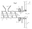
より詳細には、図2は、バレル1とバレル内に収納されたウォームスクリュー2を含むバッチチャージャーの本体を示す。バレル上のホッパー12が、バッチ材料(ガラス化可能材料および有機構成成分)のバレル内への補給を可能にしている。バッチチャージャーの頭部は、スライドゲートダンパー3および管状連結部品4を含む。スライドゲートダンパーは固定部分7とスライドゲートと呼ばれる可動部分6とを含む。炉(そのタンク壁9のみが図示されている)の方向にわずかに広がった内側表面を有する管状連結部品4は、ダンパー3の固定部分7に締結されている。管状連結部品4は、投入オリフィス10内に挿入される。ダンパー3のスライドゲート6および連結部品4の各々には内部ダクトシステム5が通っており、その中に冷却液を流すことができるようになっている。図1において、スライドゲート6は開放位置にある。すなわち、その円形アパーチャはバレル1の円形断面および連結部品4の円形断面の上に重ね合わされ、こうして、バッチ材料を投入するためのチャネルを画定し、このチャネルは投入オリフィス10上に開放する。ガラス浴11の理論的レベルは破線で示されている。
More particularly, FIG. 2 shows the body of a batch charger that includes a
図2はあらゆる点で図1と同一であるが、ただし可動部分6(スライドゲート)は閉鎖され、こうして、バレル1の内側を連結部品4の開口部から、ひいては炉の内側から切り離している。
FIG. 2 is identical in all respects to FIG. 1 except that the movable part 6 (slide gate) is closed, thus separating the inside of the
図3は、ダンパーの固定部分およびバッチチャージャーの残りの部分から分離された可動部分6を示す。この可動部分6またはスライドゲートは、一方の半分に円形アパーチャ13を含む中空の金属プレートである。出口の第1のダクト5aを出口の第2のダクト5bが中空金属プレート内のキャビティと連通し、冷却液を流すための内部ダクトシステムを形成する。
FIG. 3 shows the movable part 6 separated from the fixed part of the damper and the rest of the batch charger. This movable part 6 or slide gate is a hollow metal plate that includes a
Claims (15)
バレル(1)と、バッチ材料を搬送するための前記バレル内に収納されている機械式搬送システム(2)と、を伴う本体と、
スライドゲートダンパー(3)と、該スライドゲートダンパー(3)に締結されかつ炉のタンクの壁内に設けられた投入オリフィス内に少なくとも部分的に挿入されるように意図されている連結部品(4)と、を伴うバレルの端部に取外し可能な形で締結されている頭部であって、スライドゲートダンパー(3)と連結部品(4)とが冷却液供給源に連結可能である内部ダクトシステム(5)を含んでいる頭部と、
を備えることを特徴とするバッチチャージャー。 In a batch charger for feeding batch material into a glass melting furnace at a level located below the level of molten glass,
A body with a barrel (1) and a mechanical transport system (2) housed in the barrel for transporting batch material;
A slide gate damper (3), the slide gate damper at least partially inserted intended to consolidated parts are to be in a turned orifice provided in the wall of the fastened and furnace tank (3) ( 4), a head fastened in a detachable manner to the end of the barrel with the slide gate damper (3) and the connecting part (4) being connectable to the coolant supply source A head containing a duct system (5);
A batch charger characterized by comprising.
溶融材料の排出溝の位置によって画定されるガラスの理論的レベルより下で、炉のタンクの壁内に位置設定された投入オリフィス(10)を伴うガラス溶融炉と、
請求項1〜8の何れか一項に記載のバッチチャージャーと、を含み、
バッチチャージャーの連結部品(4)が少なくとも部分的に炉の投入オリフィス(10)内に挿入されていることを特徴とするガラス溶融設備。 In equipment for melting glass,
A glass melting furnace with an input orifice (10) positioned in the wall of the furnace tank below the theoretical level of glass defined by the location of the molten material discharge channel;
A batch charger according to any one of claims 1 to 8,
Glass melting facility, characterized in that the connecting part (4) of the batch charger is inserted at least partially into the furnace input orifice (10).
スライドゲートダンパー(3)および連結部品(4)の内部ダクトシステム(5)を通して冷却液を流動させることによりバッチチャージャーの頭部を冷却するステップと、
を含むことを特徴とする請求項11に記載の溶融方法。 Batch material into a glass melting furnace using a batch charger according to any one of claims 1 to 8 through an input orifice (10) positioned in the wall of the furnace tank below the level of molten glass. the comprising the steps of complement feed, the batch charger head is connected to the insertion orifice (10) by concatenation component (4), thus slide gate at the level of the batch material is located below the level of the molten glass via a damper (3) and consolidated parts (4) is made to enter into the furnace, comprising the steps,
A step of cooling the head of the batch charger by flowing coolant through the internal duct system (5) of the slide gate damper (3) and connecting piece (4),
The melting method according to claim 11, comprising:
Applications Claiming Priority (3)
| Application Number | Priority Date | Filing Date | Title |
|---|---|---|---|
| FR1251966 | 2012-03-05 | ||
| FR1251966A FR2987617B1 (en) | 2012-03-05 | 2012-03-05 | RUFFER WITH REMOVABLE HEAD FOR IMMERSE ENFORCEMENT |
| PCT/FR2013/050459 WO2013132184A1 (en) | 2012-03-05 | 2013-03-04 | Batch-charging machine with removable head for submerged batch-charging |
Publications (3)
| Publication Number | Publication Date |
|---|---|
| JP2015511927A JP2015511927A (en) | 2015-04-23 |
| JP2015511927A5 JP2015511927A5 (en) | 2016-03-24 |
| JP6054990B2 true JP6054990B2 (en) | 2016-12-27 |
Family
ID=47913479
Family Applications (1)
| Application Number | Title | Priority Date | Filing Date |
|---|---|---|---|
| JP2014560431A Active JP6054990B2 (en) | 2012-03-05 | 2013-03-04 | Batch charger with removable head for submerged batch loading |
Country Status (18)
| Country | Link |
|---|---|
| US (1) | US9394192B2 (en) |
| EP (1) | EP2822902B1 (en) |
| JP (1) | JP6054990B2 (en) |
| KR (1) | KR102057074B1 (en) |
| CA (1) | CA2865529C (en) |
| DK (1) | DK2822902T3 (en) |
| ES (1) | ES2586595T3 (en) |
| FR (1) | FR2987617B1 (en) |
| HR (1) | HRP20161046T1 (en) |
| HU (1) | HUE028851T2 (en) |
| MX (1) | MX349874B (en) |
| PL (1) | PL2822902T3 (en) |
| RS (1) | RS55120B1 (en) |
| RU (1) | RU2615550C2 (en) |
| SA (1) | SA113340354B1 (en) |
| SI (1) | SI2822902T1 (en) |
| UA (1) | UA110885C2 (en) |
| WO (1) | WO2013132184A1 (en) |
Families Citing this family (20)
| Publication number | Priority date | Publication date | Assignee | Title |
|---|---|---|---|---|
| GB201313656D0 (en) | 2013-07-31 | 2013-09-11 | Knauf Insulation Doo Skofja Loka | Melting of vitrifiable material |
| EA032238B1 (en) * | 2014-10-10 | 2019-04-30 | Оутотек (Финлэнд) Ой | Weir module for a pyrometallurgical furnace |
| GB201501307D0 (en) * | 2015-01-27 | 2015-03-11 | Knauf Insulation And Knauf Insulation Doo Skofja Loka And Knauf Insulation Gmbh And Knauf Insulation | Process for the preparation of a silica melt |
| GB201501312D0 (en) * | 2015-01-27 | 2015-03-11 | Knauf Insulation And Knauf Insulation Llc And Knauf Insulation Gmbh And Knauf Insulation Doo Skofja | Melter feeding system |
| US20180244554A1 (en) * | 2015-08-31 | 2018-08-30 | Ocv Intellectual Capital, Llc | Batch inlet spool |
| FR3042187B1 (en) | 2015-10-08 | 2023-08-25 | Saint Gobain Isover | MINERAL FIBERS |
| FR3074165B1 (en) * | 2017-11-30 | 2020-12-11 | Saint Gobain Isover | MOBILE CONVEYOR IN TRANSLATION |
| FR3074166B1 (en) * | 2017-11-30 | 2020-12-11 | Saint Gobain Isover | INJECTING FLUID INTO A BURNER |
| FR3086740B1 (en) * | 2018-09-28 | 2021-01-01 | Saint Gobain Isover | SUBMERSIBLE BURNER OVEN |
| US11358895B2 (en) | 2018-11-15 | 2022-06-14 | Owens-Brockway Glass Container Inc. | Batch charger for a melting chamber |
| US11084749B2 (en) | 2018-11-20 | 2021-08-10 | Owens-Brockway Glass Container Inc. | Batch inlet and cleaning device for glass melter |
| US20220411306A1 (en) * | 2020-09-30 | 2022-12-29 | Owens-Brockway Glass Container Inc. | Feeder Alcove and Batch Feeding Apparats for a Melter |
| US11912608B2 (en) | 2019-10-01 | 2024-02-27 | Owens-Brockway Glass Container Inc. | Glass manufacturing |
| ES2902529T3 (en) | 2019-12-11 | 2022-03-28 | International Partners In Glass Res Ipgr E V | Method and device for preparing a batch material to feed a glass melting furnace |
| FR3106132B1 (en) * | 2020-01-15 | 2023-05-19 | Saint Gobain Isover | Fusion of vitrifiable material |
| WO2022072670A1 (en) * | 2020-09-30 | 2022-04-07 | Owens-Brockway Glass Container Inc. | Submerged feedstock charging of melting vessels |
| FR3120233A1 (en) * | 2021-02-26 | 2022-09-02 | Saint-Gobain Isover | Furnace regulation |
| US20220332622A1 (en) * | 2021-04-16 | 2022-10-20 | Owens-Brockway Glass Container Inc. | Feeder Tank For A Glass Melter |
| CN113292224A (en) * | 2021-04-19 | 2021-08-24 | 信义节能玻璃(芜湖)有限公司 | Glass processing melting system |
| WO2022268321A1 (en) | 2021-06-24 | 2022-12-29 | International Partners In Glass Research (Ipgr) E.V. | Device and method for feeding glass batch material into a glass melting surface |
Family Cites Families (17)
| Publication number | Priority date | Publication date | Assignee | Title |
|---|---|---|---|---|
| US1761229A (en) * | 1926-10-25 | 1930-06-03 | Libbey Owens Glass Co | Batch-feeding mechanism |
| US1834631A (en) * | 1928-12-05 | 1931-12-01 | Hartford Empire Co | Apparatus for making glass |
| US2354807A (en) * | 1937-12-24 | 1944-08-01 | Pittsburgh Plate Glass Co | Manufacture of vesicular glass |
| US2262070A (en) * | 1938-11-15 | 1941-11-11 | Porcelain Enamel & Mfg Company | Method of and apparatus for charging and smelting vitreous enamels |
| US2479805A (en) * | 1946-08-15 | 1949-08-23 | Toledo Engineering Company Inc | Method of and apparatus for feeding batch materials |
| US3573017A (en) * | 1968-11-04 | 1971-03-30 | Owens Corning Fiberglass Corp | Method and apparatus for melting and supplying heat-softenable materials in a process |
| US3725022A (en) * | 1971-02-12 | 1973-04-03 | Owens Illinois Inc | Method of feeding glass batch |
| US4226564A (en) * | 1977-05-24 | 1980-10-07 | Asahi Glass Company, Limited | Apparatus for feeding glass batch materials into a glass melting furnace |
| US4290797A (en) * | 1980-02-06 | 1981-09-22 | Tropicana Products, Inc. | Apparatus for dispensing and submersing batch materials in a molten glass furnace |
| WO1999035099A1 (en) | 1998-01-09 | 1999-07-15 | Saint-Gobain Vitrage | Method and device for melting and refining materials capable of being vitrified |
| BR0004634B1 (en) * | 1999-02-05 | 2010-02-09 | process for the manufacture of compounds based on one or more alkali and / or alkaline earth metal silicates and / or rare earths, apparatus for doing the same, use of the process or apparatus, and process for obtaining glass. | |
| US6349570B1 (en) | 1999-04-14 | 2002-02-26 | Merkle Engineers, Inc. | In-barrel wetting screw charger |
| US7926301B2 (en) * | 2007-08-16 | 2011-04-19 | Corning Incorporated | Method and apparatus for controlling the level of a molten material in a glass manufacturing system |
| PL2072474T3 (en) * | 2007-12-19 | 2011-09-30 | Schwenk Daemmtechnik Gmbh & Co Kg | Method and device for recycling mineral wool waste containing organic elements |
| DE202009014937U1 (en) * | 2009-05-26 | 2010-09-02 | Eme Maschinenfabrik Clasen Gmbh | Apparatus for feeding glass melting furnaces with free-flowing glass mixtures |
| US8573006B2 (en) * | 2012-01-09 | 2013-11-05 | Owens-Brockway Glass Container Inc. | Batch charger cooling |
| RU146193U1 (en) * | 2014-05-28 | 2014-10-10 | Общество с ограниченной ответственностью "Русский базальт" | LOAD LOADER IN FURNACE |
-
2012
- 2012-03-05 FR FR1251966A patent/FR2987617B1/en active Active
-
2013
- 2013-03-04 US US14/382,980 patent/US9394192B2/en active Active
- 2013-03-04 PL PL13711090.4T patent/PL2822902T3/en unknown
- 2013-03-04 CA CA2865529A patent/CA2865529C/en active Active
- 2013-03-04 RS RS20160680A patent/RS55120B1/en unknown
- 2013-03-04 RU RU2014140214A patent/RU2615550C2/en active
- 2013-03-04 WO PCT/FR2013/050459 patent/WO2013132184A1/en active Application Filing
- 2013-03-04 EP EP13711090.4A patent/EP2822902B1/en active Active
- 2013-03-04 SA SA113340354A patent/SA113340354B1/en unknown
- 2013-03-04 DK DK13711090.4T patent/DK2822902T3/en active
- 2013-03-04 SI SI201330272A patent/SI2822902T1/en unknown
- 2013-03-04 JP JP2014560431A patent/JP6054990B2/en active Active
- 2013-03-04 ES ES13711090.4T patent/ES2586595T3/en active Active
- 2013-03-04 HU HUE13711090A patent/HUE028851T2/en unknown
- 2013-03-04 MX MX2014010559A patent/MX349874B/en active IP Right Grant
- 2013-03-04 KR KR1020147024313A patent/KR102057074B1/en active IP Right Grant
- 2013-04-03 UA UAA201410830A patent/UA110885C2/en unknown
-
2016
- 2016-08-18 HR HRP20161046TT patent/HRP20161046T1/en unknown
Also Published As
| Publication number | Publication date |
|---|---|
| RU2615550C2 (en) | 2017-04-05 |
| WO2013132184A1 (en) | 2013-09-12 |
| ES2586595T3 (en) | 2016-10-17 |
| RS55120B1 (en) | 2016-12-30 |
| KR20140139489A (en) | 2014-12-05 |
| US9394192B2 (en) | 2016-07-19 |
| SI2822902T1 (en) | 2016-10-28 |
| MX2014010559A (en) | 2014-12-05 |
| EP2822902B1 (en) | 2016-05-18 |
| US20150013386A1 (en) | 2015-01-15 |
| SA113340354B1 (en) | 2015-08-20 |
| CA2865529A1 (en) | 2013-09-12 |
| MX349874B (en) | 2017-08-17 |
| FR2987617B1 (en) | 2017-03-24 |
| CA2865529C (en) | 2020-10-27 |
| HUE028851T2 (en) | 2017-01-30 |
| HRP20161046T1 (en) | 2016-10-21 |
| UA110885C2 (en) | 2016-02-25 |
| JP2015511927A (en) | 2015-04-23 |
| PL2822902T3 (en) | 2016-12-30 |
| CN104144888A (en) | 2014-11-12 |
| EP2822902A1 (en) | 2015-01-14 |
| KR102057074B1 (en) | 2019-12-18 |
| RU2014140214A (en) | 2016-04-27 |
| FR2987617A1 (en) | 2013-09-06 |
| DK2822902T3 (en) | 2016-08-29 |
Similar Documents
| Publication | Publication Date | Title |
|---|---|---|
| JP6054990B2 (en) | Batch charger with removable head for submerged batch loading | |
| US8650914B2 (en) | Methods and apparatus for recycling glass products using submerged combustion | |
| CN101743207B (en) | Oven and oxy-combustible method for melting vitrifiable materials | |
| IT9002920A1 (en) | METHOD OF PREHEATING IRON SCRAP THROUGH PYROLYSIS OF RESIN RESIDUES CONTAINED WITH ITS INTEGRAL RECOVERY OF THEIR ENERGY CONTENT AND IMPROVEMENT OF THE STEEL CYCLE | |
| CN104302997B (en) | Start-up torch | |
| CN104641004A (en) | Blow-pipe structure | |
| CN104870381A (en) | Process and apparatus for forming man-made vitreous fibres | |
| CN201242149Y (en) | Burner system | |
| CN104918893A (en) | Process and apparatus for forming man-made vitreous fibres | |
| CN104854040A (en) | Process and apparatus for forming man-made vitreous fibres | |
| US20190271465A1 (en) | Auxiliary burner for electric furnace | |
| EA027185B1 (en) | Method for recycling material when making a mineral melt | |
| CN104144888B (en) | The loading machine with removable head for submergence charging | |
| CN208684772U (en) | A kind of equipment preparing rock wool | |
| RU2533565C1 (en) | Plasma method for mineral wool manufacturing and plant for its implementation | |
| CN103189320A (en) | An apparatus and method for making a mineral melt | |
| US10935234B2 (en) | Auxiliary burner for electric furnace | |
| CN104019460B (en) | A kind of water wall gasifier dross method and apparatus | |
| CN218349189U (en) | Cupola furnace | |
| JP4959615B2 (en) | Ash melting furnace | |
| RU2434744C2 (en) | Method of powder cutting of refractory material and device to this end | |
| JP5348915B2 (en) | High melting point material removal method in ash melting furnace | |
| JP6331149B2 (en) | Waste gasification and melting apparatus and waste gasification and melting method | |
| TR2023002299A2 (en) | METHOD FOR PRODUCING MINERAL INSULATION | |
| JP3804014B2 (en) | Combustion apparatus and combustion method using waste plastic powder as auxiliary fuel |
Legal Events
| Date | Code | Title | Description |
|---|---|---|---|
| A521 | Request for written amendment filed |
Free format text: JAPANESE INTERMEDIATE CODE: A523 Effective date: 20160204 |
|
| A621 | Written request for application examination |
Free format text: JAPANESE INTERMEDIATE CODE: A621 Effective date: 20160204 |
|
| A871 | Explanation of circumstances concerning accelerated examination |
Free format text: JAPANESE INTERMEDIATE CODE: A871 Effective date: 20160607 |
|
| A975 | Report on accelerated examination |
Free format text: JAPANESE INTERMEDIATE CODE: A971005 Effective date: 20160701 |
|
| A131 | Notification of reasons for refusal |
Free format text: JAPANESE INTERMEDIATE CODE: A131 Effective date: 20160705 |
|
| A521 | Request for written amendment filed |
Free format text: JAPANESE INTERMEDIATE CODE: A523 Effective date: 20161005 |
|
| TRDD | Decision of grant or rejection written | ||
| A01 | Written decision to grant a patent or to grant a registration (utility model) |
Free format text: JAPANESE INTERMEDIATE CODE: A01 Effective date: 20161101 |
|
| A61 | First payment of annual fees (during grant procedure) |
Free format text: JAPANESE INTERMEDIATE CODE: A61 Effective date: 20161201 |
|
| R150 | Certificate of patent or registration of utility model |
Ref document number: 6054990 Country of ref document: JP Free format text: JAPANESE INTERMEDIATE CODE: R150 |
|
| R250 | Receipt of annual fees |
Free format text: JAPANESE INTERMEDIATE CODE: R250 |
|
| R250 | Receipt of annual fees |
Free format text: JAPANESE INTERMEDIATE CODE: R250 |
|
| R250 | Receipt of annual fees |
Free format text: JAPANESE INTERMEDIATE CODE: R250 |
|
| R250 | Receipt of annual fees |
Free format text: JAPANESE INTERMEDIATE CODE: R250 |
|
| R250 | Receipt of annual fees |
Free format text: JAPANESE INTERMEDIATE CODE: R250 |