JP6052257B2 - Reducing agent addition device - Google Patents
Reducing agent addition device Download PDFInfo
- Publication number
- JP6052257B2 JP6052257B2 JP2014190155A JP2014190155A JP6052257B2 JP 6052257 B2 JP6052257 B2 JP 6052257B2 JP 2014190155 A JP2014190155 A JP 2014190155A JP 2014190155 A JP2014190155 A JP 2014190155A JP 6052257 B2 JP6052257 B2 JP 6052257B2
- Authority
- JP
- Japan
- Prior art keywords
- ozone
- air
- reduction
- reducing agent
- air pump
- Prior art date
- Legal status (The legal status is an assumption and is not a legal conclusion. Google has not performed a legal analysis and makes no representation as to the accuracy of the status listed.)
- Expired - Fee Related
Links
Images
Classifications
-
- F—MECHANICAL ENGINEERING; LIGHTING; HEATING; WEAPONS; BLASTING
- F01—MACHINES OR ENGINES IN GENERAL; ENGINE PLANTS IN GENERAL; STEAM ENGINES
- F01N—GAS-FLOW SILENCERS OR EXHAUST APPARATUS FOR MACHINES OR ENGINES IN GENERAL; GAS-FLOW SILENCERS OR EXHAUST APPARATUS FOR INTERNAL-COMBUSTION ENGINES
- F01N3/00—Exhaust or silencing apparatus having means for purifying, rendering innocuous, or otherwise treating exhaust
- F01N3/08—Exhaust or silencing apparatus having means for purifying, rendering innocuous, or otherwise treating exhaust for rendering innocuous
- F01N3/0807—Exhaust or silencing apparatus having means for purifying, rendering innocuous, or otherwise treating exhaust for rendering innocuous by using absorbents or adsorbents
- F01N3/0828—Exhaust or silencing apparatus having means for purifying, rendering innocuous, or otherwise treating exhaust for rendering innocuous by using absorbents or adsorbents characterised by the absorbed or adsorbed substances
- F01N3/0842—Nitrogen oxides
-
- B—PERFORMING OPERATIONS; TRANSPORTING
- B01—PHYSICAL OR CHEMICAL PROCESSES OR APPARATUS IN GENERAL
- B01D—SEPARATION
- B01D53/00—Separation of gases or vapours; Recovering vapours of volatile solvents from gases; Chemical or biological purification of waste gases, e.g. engine exhaust gases, smoke, fumes, flue gases, aerosols
- B01D53/34—Chemical or biological purification of waste gases
- B01D53/92—Chemical or biological purification of waste gases of engine exhaust gases
- B01D53/94—Chemical or biological purification of waste gases of engine exhaust gases by catalytic processes
- B01D53/9404—Removing only nitrogen compounds
- B01D53/9409—Nitrogen oxides
- B01D53/9431—Processes characterised by a specific device
-
- B—PERFORMING OPERATIONS; TRANSPORTING
- B01—PHYSICAL OR CHEMICAL PROCESSES OR APPARATUS IN GENERAL
- B01D—SEPARATION
- B01D53/00—Separation of gases or vapours; Recovering vapours of volatile solvents from gases; Chemical or biological purification of waste gases, e.g. engine exhaust gases, smoke, fumes, flue gases, aerosols
- B01D53/34—Chemical or biological purification of waste gases
- B01D53/92—Chemical or biological purification of waste gases of engine exhaust gases
- B01D53/94—Chemical or biological purification of waste gases of engine exhaust gases by catalytic processes
- B01D53/9495—Controlling the catalytic process
-
- F—MECHANICAL ENGINEERING; LIGHTING; HEATING; WEAPONS; BLASTING
- F01—MACHINES OR ENGINES IN GENERAL; ENGINE PLANTS IN GENERAL; STEAM ENGINES
- F01N—GAS-FLOW SILENCERS OR EXHAUST APPARATUS FOR MACHINES OR ENGINES IN GENERAL; GAS-FLOW SILENCERS OR EXHAUST APPARATUS FOR INTERNAL-COMBUSTION ENGINES
- F01N3/00—Exhaust or silencing apparatus having means for purifying, rendering innocuous, or otherwise treating exhaust
- F01N3/08—Exhaust or silencing apparatus having means for purifying, rendering innocuous, or otherwise treating exhaust for rendering innocuous
- F01N3/0807—Exhaust or silencing apparatus having means for purifying, rendering innocuous, or otherwise treating exhaust for rendering innocuous by using absorbents or adsorbents
- F01N3/0814—Exhaust or silencing apparatus having means for purifying, rendering innocuous, or otherwise treating exhaust for rendering innocuous by using absorbents or adsorbents combined with catalytic converters, e.g. NOx absorption/storage reduction catalysts
-
- F—MECHANICAL ENGINEERING; LIGHTING; HEATING; WEAPONS; BLASTING
- F01—MACHINES OR ENGINES IN GENERAL; ENGINE PLANTS IN GENERAL; STEAM ENGINES
- F01N—GAS-FLOW SILENCERS OR EXHAUST APPARATUS FOR MACHINES OR ENGINES IN GENERAL; GAS-FLOW SILENCERS OR EXHAUST APPARATUS FOR INTERNAL-COMBUSTION ENGINES
- F01N3/00—Exhaust or silencing apparatus having means for purifying, rendering innocuous, or otherwise treating exhaust
- F01N3/08—Exhaust or silencing apparatus having means for purifying, rendering innocuous, or otherwise treating exhaust for rendering innocuous
- F01N3/0807—Exhaust or silencing apparatus having means for purifying, rendering innocuous, or otherwise treating exhaust for rendering innocuous by using absorbents or adsorbents
- F01N3/0871—Exhaust or silencing apparatus having means for purifying, rendering innocuous, or otherwise treating exhaust for rendering innocuous by using absorbents or adsorbents using means for controlling, e.g. purging, the absorbents or adsorbents
-
- F—MECHANICAL ENGINEERING; LIGHTING; HEATING; WEAPONS; BLASTING
- F01—MACHINES OR ENGINES IN GENERAL; ENGINE PLANTS IN GENERAL; STEAM ENGINES
- F01N—GAS-FLOW SILENCERS OR EXHAUST APPARATUS FOR MACHINES OR ENGINES IN GENERAL; GAS-FLOW SILENCERS OR EXHAUST APPARATUS FOR INTERNAL-COMBUSTION ENGINES
- F01N3/00—Exhaust or silencing apparatus having means for purifying, rendering innocuous, or otherwise treating exhaust
- F01N3/08—Exhaust or silencing apparatus having means for purifying, rendering innocuous, or otherwise treating exhaust for rendering innocuous
- F01N3/10—Exhaust or silencing apparatus having means for purifying, rendering innocuous, or otherwise treating exhaust for rendering innocuous by thermal or catalytic conversion of noxious components of exhaust
- F01N3/18—Exhaust or silencing apparatus having means for purifying, rendering innocuous, or otherwise treating exhaust for rendering innocuous by thermal or catalytic conversion of noxious components of exhaust characterised by methods of operation; Control
- F01N3/20—Exhaust or silencing apparatus having means for purifying, rendering innocuous, or otherwise treating exhaust for rendering innocuous by thermal or catalytic conversion of noxious components of exhaust characterised by methods of operation; Control specially adapted for catalytic conversion
- F01N3/206—Adding periodically or continuously substances to exhaust gases for promoting purification, e.g. catalytic material in liquid form, NOx reducing agents
- F01N3/2066—Selective catalytic reduction [SCR]
-
- F—MECHANICAL ENGINEERING; LIGHTING; HEATING; WEAPONS; BLASTING
- F01—MACHINES OR ENGINES IN GENERAL; ENGINE PLANTS IN GENERAL; STEAM ENGINES
- F01N—GAS-FLOW SILENCERS OR EXHAUST APPARATUS FOR MACHINES OR ENGINES IN GENERAL; GAS-FLOW SILENCERS OR EXHAUST APPARATUS FOR INTERNAL-COMBUSTION ENGINES
- F01N3/00—Exhaust or silencing apparatus having means for purifying, rendering innocuous, or otherwise treating exhaust
- F01N3/08—Exhaust or silencing apparatus having means for purifying, rendering innocuous, or otherwise treating exhaust for rendering innocuous
- F01N3/10—Exhaust or silencing apparatus having means for purifying, rendering innocuous, or otherwise treating exhaust for rendering innocuous by thermal or catalytic conversion of noxious components of exhaust
- F01N3/24—Exhaust or silencing apparatus having means for purifying, rendering innocuous, or otherwise treating exhaust for rendering innocuous by thermal or catalytic conversion of noxious components of exhaust characterised by constructional aspects of converting apparatus
- F01N3/30—Arrangements for supply of additional air
- F01N3/303—Filtering additional air
-
- F—MECHANICAL ENGINEERING; LIGHTING; HEATING; WEAPONS; BLASTING
- F01—MACHINES OR ENGINES IN GENERAL; ENGINE PLANTS IN GENERAL; STEAM ENGINES
- F01N—GAS-FLOW SILENCERS OR EXHAUST APPARATUS FOR MACHINES OR ENGINES IN GENERAL; GAS-FLOW SILENCERS OR EXHAUST APPARATUS FOR INTERNAL-COMBUSTION ENGINES
- F01N3/00—Exhaust or silencing apparatus having means for purifying, rendering innocuous, or otherwise treating exhaust
- F01N3/08—Exhaust or silencing apparatus having means for purifying, rendering innocuous, or otherwise treating exhaust for rendering innocuous
- F01N3/10—Exhaust or silencing apparatus having means for purifying, rendering innocuous, or otherwise treating exhaust for rendering innocuous by thermal or catalytic conversion of noxious components of exhaust
- F01N3/24—Exhaust or silencing apparatus having means for purifying, rendering innocuous, or otherwise treating exhaust for rendering innocuous by thermal or catalytic conversion of noxious components of exhaust characterised by constructional aspects of converting apparatus
- F01N3/30—Arrangements for supply of additional air
- F01N3/32—Arrangements for supply of additional air using air pump
-
- B—PERFORMING OPERATIONS; TRANSPORTING
- B01—PHYSICAL OR CHEMICAL PROCESSES OR APPARATUS IN GENERAL
- B01D—SEPARATION
- B01D2251/00—Reactants
- B01D2251/10—Oxidants
- B01D2251/104—Ozone
-
- F—MECHANICAL ENGINEERING; LIGHTING; HEATING; WEAPONS; BLASTING
- F01—MACHINES OR ENGINES IN GENERAL; ENGINE PLANTS IN GENERAL; STEAM ENGINES
- F01N—GAS-FLOW SILENCERS OR EXHAUST APPARATUS FOR MACHINES OR ENGINES IN GENERAL; GAS-FLOW SILENCERS OR EXHAUST APPARATUS FOR INTERNAL-COMBUSTION ENGINES
- F01N13/00—Exhaust or silencing apparatus characterised by constructional features
- F01N13/009—Exhaust or silencing apparatus characterised by constructional features having two or more separate purifying devices arranged in series
- F01N13/0097—Exhaust or silencing apparatus characterised by constructional features having two or more separate purifying devices arranged in series the purifying devices are arranged in a single housing
-
- F—MECHANICAL ENGINEERING; LIGHTING; HEATING; WEAPONS; BLASTING
- F01—MACHINES OR ENGINES IN GENERAL; ENGINE PLANTS IN GENERAL; STEAM ENGINES
- F01N—GAS-FLOW SILENCERS OR EXHAUST APPARATUS FOR MACHINES OR ENGINES IN GENERAL; GAS-FLOW SILENCERS OR EXHAUST APPARATUS FOR INTERNAL-COMBUSTION ENGINES
- F01N2240/00—Combination or association of two or more different exhaust treating devices, or of at least one such device with an auxiliary device, not covered by indexing codes F01N2230/00 or F01N2250/00, one of the devices being
- F01N2240/16—Combination or association of two or more different exhaust treating devices, or of at least one such device with an auxiliary device, not covered by indexing codes F01N2230/00 or F01N2250/00, one of the devices being an electric heater, i.e. a resistance heater
-
- F—MECHANICAL ENGINEERING; LIGHTING; HEATING; WEAPONS; BLASTING
- F01—MACHINES OR ENGINES IN GENERAL; ENGINE PLANTS IN GENERAL; STEAM ENGINES
- F01N—GAS-FLOW SILENCERS OR EXHAUST APPARATUS FOR MACHINES OR ENGINES IN GENERAL; GAS-FLOW SILENCERS OR EXHAUST APPARATUS FOR INTERNAL-COMBUSTION ENGINES
- F01N2240/00—Combination or association of two or more different exhaust treating devices, or of at least one such device with an auxiliary device, not covered by indexing codes F01N2230/00 or F01N2250/00, one of the devices being
- F01N2240/30—Combination or association of two or more different exhaust treating devices, or of at least one such device with an auxiliary device, not covered by indexing codes F01N2230/00 or F01N2250/00, one of the devices being a fuel reformer
-
- F—MECHANICAL ENGINEERING; LIGHTING; HEATING; WEAPONS; BLASTING
- F01—MACHINES OR ENGINES IN GENERAL; ENGINE PLANTS IN GENERAL; STEAM ENGINES
- F01N—GAS-FLOW SILENCERS OR EXHAUST APPARATUS FOR MACHINES OR ENGINES IN GENERAL; GAS-FLOW SILENCERS OR EXHAUST APPARATUS FOR INTERNAL-COMBUSTION ENGINES
- F01N2240/00—Combination or association of two or more different exhaust treating devices, or of at least one such device with an auxiliary device, not covered by indexing codes F01N2230/00 or F01N2250/00, one of the devices being
- F01N2240/38—Combination or association of two or more different exhaust treating devices, or of at least one such device with an auxiliary device, not covered by indexing codes F01N2230/00 or F01N2250/00, one of the devices being an ozone (O3) generator, e.g. for adding ozone after generation of ozone from air
-
- F—MECHANICAL ENGINEERING; LIGHTING; HEATING; WEAPONS; BLASTING
- F01—MACHINES OR ENGINES IN GENERAL; ENGINE PLANTS IN GENERAL; STEAM ENGINES
- F01N—GAS-FLOW SILENCERS OR EXHAUST APPARATUS FOR MACHINES OR ENGINES IN GENERAL; GAS-FLOW SILENCERS OR EXHAUST APPARATUS FOR INTERNAL-COMBUSTION ENGINES
- F01N2260/00—Exhaust treating devices having provisions not otherwise provided for
- F01N2260/26—Exhaust treating devices having provisions not otherwise provided for for preventing enter of dirt into the device
-
- F—MECHANICAL ENGINEERING; LIGHTING; HEATING; WEAPONS; BLASTING
- F01—MACHINES OR ENGINES IN GENERAL; ENGINE PLANTS IN GENERAL; STEAM ENGINES
- F01N—GAS-FLOW SILENCERS OR EXHAUST APPARATUS FOR MACHINES OR ENGINES IN GENERAL; GAS-FLOW SILENCERS OR EXHAUST APPARATUS FOR INTERNAL-COMBUSTION ENGINES
- F01N2560/00—Exhaust systems with means for detecting or measuring exhaust gas components or characteristics
- F01N2560/06—Exhaust systems with means for detecting or measuring exhaust gas components or characteristics the means being a temperature sensor
-
- F—MECHANICAL ENGINEERING; LIGHTING; HEATING; WEAPONS; BLASTING
- F01—MACHINES OR ENGINES IN GENERAL; ENGINE PLANTS IN GENERAL; STEAM ENGINES
- F01N—GAS-FLOW SILENCERS OR EXHAUST APPARATUS FOR MACHINES OR ENGINES IN GENERAL; GAS-FLOW SILENCERS OR EXHAUST APPARATUS FOR INTERNAL-COMBUSTION ENGINES
- F01N2560/00—Exhaust systems with means for detecting or measuring exhaust gas components or characteristics
- F01N2560/08—Exhaust systems with means for detecting or measuring exhaust gas components or characteristics the means being a pressure sensor
-
- F—MECHANICAL ENGINEERING; LIGHTING; HEATING; WEAPONS; BLASTING
- F01—MACHINES OR ENGINES IN GENERAL; ENGINE PLANTS IN GENERAL; STEAM ENGINES
- F01N—GAS-FLOW SILENCERS OR EXHAUST APPARATUS FOR MACHINES OR ENGINES IN GENERAL; GAS-FLOW SILENCERS OR EXHAUST APPARATUS FOR INTERNAL-COMBUSTION ENGINES
- F01N2570/00—Exhaust treating apparatus eliminating, absorbing or adsorbing specific elements or compounds
- F01N2570/14—Nitrogen oxides
-
- F—MECHANICAL ENGINEERING; LIGHTING; HEATING; WEAPONS; BLASTING
- F01—MACHINES OR ENGINES IN GENERAL; ENGINE PLANTS IN GENERAL; STEAM ENGINES
- F01N—GAS-FLOW SILENCERS OR EXHAUST APPARATUS FOR MACHINES OR ENGINES IN GENERAL; GAS-FLOW SILENCERS OR EXHAUST APPARATUS FOR INTERNAL-COMBUSTION ENGINES
- F01N2610/00—Adding substances to exhaust gases
- F01N2610/03—Adding substances to exhaust gases the substance being hydrocarbons, e.g. engine fuel
-
- F—MECHANICAL ENGINEERING; LIGHTING; HEATING; WEAPONS; BLASTING
- F01—MACHINES OR ENGINES IN GENERAL; ENGINE PLANTS IN GENERAL; STEAM ENGINES
- F01N—GAS-FLOW SILENCERS OR EXHAUST APPARATUS FOR MACHINES OR ENGINES IN GENERAL; GAS-FLOW SILENCERS OR EXHAUST APPARATUS FOR INTERNAL-COMBUSTION ENGINES
- F01N2610/00—Adding substances to exhaust gases
- F01N2610/08—Adding substances to exhaust gases with prior mixing of the substances with a gas, e.g. air
- F01N2610/085—Controlling the air supply
-
- F—MECHANICAL ENGINEERING; LIGHTING; HEATING; WEAPONS; BLASTING
- F01—MACHINES OR ENGINES IN GENERAL; ENGINE PLANTS IN GENERAL; STEAM ENGINES
- F01N—GAS-FLOW SILENCERS OR EXHAUST APPARATUS FOR MACHINES OR ENGINES IN GENERAL; GAS-FLOW SILENCERS OR EXHAUST APPARATUS FOR INTERNAL-COMBUSTION ENGINES
- F01N2900/00—Details of electrical control or of the monitoring of the exhaust gas treating apparatus
- F01N2900/06—Parameters used for exhaust control or diagnosing
- F01N2900/14—Parameters used for exhaust control or diagnosing said parameters being related to the exhaust gas
- F01N2900/1406—Exhaust gas pressure
-
- F—MECHANICAL ENGINEERING; LIGHTING; HEATING; WEAPONS; BLASTING
- F01—MACHINES OR ENGINES IN GENERAL; ENGINE PLANTS IN GENERAL; STEAM ENGINES
- F01N—GAS-FLOW SILENCERS OR EXHAUST APPARATUS FOR MACHINES OR ENGINES IN GENERAL; GAS-FLOW SILENCERS OR EXHAUST APPARATUS FOR INTERNAL-COMBUSTION ENGINES
- F01N2900/00—Details of electrical control or of the monitoring of the exhaust gas treating apparatus
- F01N2900/06—Parameters used for exhaust control or diagnosing
- F01N2900/16—Parameters used for exhaust control or diagnosing said parameters being related to the exhaust apparatus, e.g. particulate filter or catalyst
- F01N2900/1602—Temperature of exhaust gas apparatus
-
- F—MECHANICAL ENGINEERING; LIGHTING; HEATING; WEAPONS; BLASTING
- F02—COMBUSTION ENGINES; HOT-GAS OR COMBUSTION-PRODUCT ENGINE PLANTS
- F02B—INTERNAL-COMBUSTION PISTON ENGINES; COMBUSTION ENGINES IN GENERAL
- F02B37/00—Engines characterised by provision of pumps driven at least for part of the time by exhaust
- F02B37/12—Control of the pumps
- F02B37/16—Control of the pumps by bypassing charging air
- F02B37/164—Control of the pumps by bypassing charging air the bypassed air being used in an auxiliary apparatus, e.g. in an air turbine
-
- Y—GENERAL TAGGING OF NEW TECHNOLOGICAL DEVELOPMENTS; GENERAL TAGGING OF CROSS-SECTIONAL TECHNOLOGIES SPANNING OVER SEVERAL SECTIONS OF THE IPC; TECHNICAL SUBJECTS COVERED BY FORMER USPC CROSS-REFERENCE ART COLLECTIONS [XRACs] AND DIGESTS
- Y02—TECHNOLOGIES OR APPLICATIONS FOR MITIGATION OR ADAPTATION AGAINST CLIMATE CHANGE
- Y02T—CLIMATE CHANGE MITIGATION TECHNOLOGIES RELATED TO TRANSPORTATION
- Y02T10/00—Road transport of goods or passengers
- Y02T10/10—Internal combustion engine [ICE] based vehicles
- Y02T10/12—Improving ICE efficiencies
Landscapes
- Engineering & Computer Science (AREA)
- Chemical & Material Sciences (AREA)
- Chemical Kinetics & Catalysis (AREA)
- Combustion & Propulsion (AREA)
- General Engineering & Computer Science (AREA)
- Mechanical Engineering (AREA)
- Health & Medical Sciences (AREA)
- Toxicology (AREA)
- Biomedical Technology (AREA)
- Environmental & Geological Engineering (AREA)
- Analytical Chemistry (AREA)
- General Chemical & Material Sciences (AREA)
- Oil, Petroleum & Natural Gas (AREA)
- Exhaust Gas After Treatment (AREA)
Description
本発明は、NOxの還元に用いる還元剤を、排気通路のうち還元触媒の上流側へ添加する還元剤添加装置に関する。 The present invention relates to a reducing agent addition device for adding a reducing agent used for NOx reduction to an upstream side of a reduction catalyst in an exhaust passage.
特許文献1に記載の還元剤添加装置は、オゾンを生成するオゾン生成器と、生成したオゾンを含む空気を送風するエアポンプと、還元剤としての燃料を噴射する噴射弁と、ヒータとを備える。そして、送風される空気と噴射された燃料との混合気をヒータで加熱することにより、空気中の酸素による燃料の酸化反応を生じさせ、燃料を改質する。そして、その改質燃料を、排気通路のうちNOx触媒上流側に添加することで、改質燃料によるNOxの還元反応をNOx触媒上で生じさせ、排気中のNOxを浄化する。なお、空気にオゾンを含ませることで、燃料の酸化反応が促進され、NOx浄化率が向上する。
The reducing agent addition apparatus described in
また、特許文献2に記載の還元剤添加装置は、過給機により加圧された吸気の一部を吸気管から取り出す分岐管を備え、分岐管により取り出された空気をエアポンプで送風させ、燃料と混合させて改質している。
Moreover, the reducing agent addition apparatus described in
しかしながら、上記特許文献1に係る装置の場合には以下の懸念がある。すなわち、例えば内燃機関の高負荷運転時等、排気通路内の圧力(排気圧)が高い場合には、エアポンプの吐出圧が不足して、混合気を排気通路へ添加できなくなる懸念がある。
However, in the case of the apparatus according to
この懸念に対し、上記特許文献2に係る装置の場合には、過給機による加圧空気をエアポンプで送風させるので、排気圧が高くても混合気を排気通路へ添加できるようになる。しかし、吸気には、ブローバイガスや内部EGRガス等により汚物が多く含まれる場合があるので、吸気を送風する特許文献2の装置の場合には、エアポンプが汚染されて故障する懸念が新たに生じる。特に、空気にオゾンを含ませてNOx浄化率向上を図ろうとした場合には、オゾン生成器も汚染されて故障する懸念が生じる。
In response to this concern, in the case of the apparatus according to
本発明は、上記問題を鑑みてなされたもので、その目的は、オゾンによるNOx浄化率向上を図るとともに、高排気圧であっても還元剤の排気通路への添加を可能にすることを、エアポンプの汚染を抑制しつつ実現できる還元剤添加装置を提供することにある。 The present invention has been made in view of the above problems, and its purpose is to improve the NOx purification rate by ozone and to enable the addition of a reducing agent to the exhaust passage even at a high exhaust pressure. An object of the present invention is to provide a reducing agent addition device that can be realized while suppressing contamination of an air pump.
ここに開示される発明は上記目的を達成するために以下の技術的手段を採用する。なお、特許請求の範囲およびこの項に記載した括弧内の符号は、後述する実施形態に記載の具体的手段との対応関係を示すものであって、発明の技術的範囲を限定するものではない。 The invention disclosed herein employs the following technical means to achieve the above object. Note that the reference numerals in parentheses described in the claims and in this section indicate the correspondence with the specific means described in the embodiments described later, and do not limit the technical scope of the invention. .
開示される発明のひとつは、内燃機関(10)の吸気を加圧して供給する過給機(11)と、内燃機関の排気通路(10ex)に配置されて排気中のNOxを還元触媒上で浄化するNOx浄化装置(12)と、を備えた燃焼システムに設けられ、排気通路のうち還元触媒の上流側へ還元剤を添加する還元剤添加装置において、空気中の酸素により還元剤を酸化させる反応室(20a)を形成し、酸化により還元剤を改質させる反応容器(20)と、空気中の酸素からオゾンを生成するオゾン生成器(30)と、オゾン生成器へ空気を送風するエアポンプ(30p)と、オゾン生成器により生成されたオゾンを含んだ空気である含オゾン空気を、反応室へ導く含オゾン空気配管(26)と、過給機により加圧された空気である加圧空気の一部を、反応室へ導く加圧空気配管(25)と、含オゾン空気を反応室へ供給するエアポンプモード、および加圧空気を反応室へ供給する過給機モードを切り替える切替装置(25v、26v)と、還元触媒の温度である触媒温度および排気通路の圧力である排気圧力に基づき、切替装置による切替作動を制御する切替制御手段(41a)と、を備えることを特徴とする。 One of the disclosed inventions is a supercharger (11) that pressurizes and supplies intake air of an internal combustion engine (10) and an exhaust passage (10ex) of the internal combustion engine so that NOx in the exhaust gas is reduced on the reduction catalyst. And a NOx purifying device (12) for purifying, wherein the reducing agent is added to the upstream side of the reduction catalyst in the exhaust passage, and the reducing agent is oxidized by oxygen in the air. A reaction vessel (20) that forms a reaction chamber (20a) and reforms the reducing agent by oxidation, an ozone generator (30) that generates ozone from oxygen in the air, and an air pump that blows air to the ozone generator (30p), ozone-containing air pipe (26) for introducing ozone-containing air, which is ozone-containing air generated by an ozone generator, to the reaction chamber, and pressure being air pressurized by a supercharger Part of the air A switching device (25v, 26v) for switching between a pressurized air pipe (25) leading to the reaction chamber, an air pump mode for supplying ozone-containing air to the reaction chamber, and a supercharger mode for supplying pressurized air to the reaction chamber; Switching control means (41a) for controlling the switching operation by the switching device based on the catalyst temperature that is the temperature of the reduction catalyst and the exhaust pressure that is the pressure of the exhaust passage.
この発明によれば、含オゾン空気を反応室へ導く含オゾン空気配管と、加圧空気を反応室へ導く加圧空気配管とを別々に備える。そして、エアポンプおよびオゾン生成器は含オゾン空気配管の経路に配置され、加圧空気配管の経路からは隔離されることとなる。そのため、エアポンプおよびオゾン生成器が、吸気に含まれる汚物で汚染されることを抑制できる。 According to this invention, the ozone-containing air pipe that leads the ozone-containing air to the reaction chamber and the pressurized air pipe that leads the pressurized air to the reaction chamber are separately provided. And an air pump and an ozone generator are arrange | positioned in the path | route of ozone-containing air piping, and will be isolated from the path | route of pressurized air piping. Therefore, it can suppress that an air pump and an ozone generator are contaminated with the filth contained in intake air.
さらに上記発明は、切替装置および切替制御手段を備える。そのため、排気通路の圧力(排気圧)が高くエアポンプでは添加困難な場合には、過給機モードに切り替えて、反応室で改質された還元剤を添加できる。また、エアポンプでの添加が可能な程度に排気圧が低く、かつ、オゾンによるNOx浄化率向上が見込めるような還元触媒温度である場合には、エアポンプモードに切り替えて、含オゾン空気で改質された還元剤を添加できる。 Furthermore, the above invention includes a switching device and a switching control means. Therefore, when the pressure in the exhaust passage (exhaust pressure) is high and it is difficult to add with an air pump, the reducing agent modified in the reaction chamber can be added by switching to the supercharger mode. Also, if the exhaust pressure is low enough to allow addition with an air pump and the reduction catalyst temperature is such that an improvement in the NOx purification rate by ozone can be expected, it is switched to the air pump mode and reformed with ozone-containing air. Reducing agent can be added.
以上により、上記発明によれば、オゾンによるNOx浄化率向上を図ることができ、それでいて、高排気圧であっても改質還元剤の添加を可能にすることを、エアポンプおよびオゾン生成器の汚染を抑制しつつ実現できる。 As described above, according to the above-described invention, it is possible to improve the NOx purification rate by ozone, and to enable the addition of the reforming reducing agent even at a high exhaust pressure, the contamination of the air pump and the ozone generator. This can be achieved while suppressing this.
以下、図面を参照しながら発明を実施するための複数の形態を説明する。各形態において、先行する形態で説明した事項に対応する部分には同一の参照符号を付して重複する説明を省略する場合がある。各形態において、構成の一部のみを説明している場合は、構成の他の部分については先行して説明した他の形態を参照し適用することができる。 Hereinafter, a plurality of modes for carrying out the invention will be described with reference to the drawings. In each embodiment, portions corresponding to the matters described in the preceding embodiment may be denoted by the same reference numerals and redundant description may be omitted. In each embodiment, when only a part of the configuration is described, the other configurations described above can be applied to other portions of the configuration.
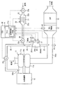
図1に示す燃焼システムは、以下に詳述する内燃機関10、過給機11、NOx浄化装置12、微粒子捕集装置(DPF13)、および還元剤添加装置を備える。燃焼システムは車両に搭載されたものであり、当該車両は、内燃機関10の出力を駆動源として走行する。内燃機関10は、圧縮自着火式のディーゼルエンジンであり、燃焼に用いる燃料には、炭化水素化合物である軽油を用いている。内燃機関10は、基本的にはリーン状態で燃焼させるように作動する。つまり、燃焼室に噴射された燃料と燃焼室に吸入される空気との比率である空燃比が、空気過剰に設定された状態で燃焼(リーン燃焼)させている。
The combustion system shown in FIG. 1 includes an
過給機11は、タービン11a、回転軸11bおよびコンプレッサ11cを備える。タービン11aは、内燃機関10の排気通路10exに配置され、排気の運動エネルギにより回転する。回転軸11bは、タービン11aおよびコンプレッサ11cの各インペラを結合することで、タービン11aの回転力をコンプレッサ11cに伝達する。コンプレッサ11cは、内燃機関10の吸気通路10inに配置され、吸気を圧縮して内燃機関10へ過給する。
The
吸気通路10inのうちコンプレッサ11cの下流側には、コンプレッサ11cで圧縮された吸気(加圧空気)を冷却する冷却器(図示せず)が配置されている。冷却器により冷却された圧縮吸気は、スロットルバルブ(図示せず)により流量調整され、内燃機関10が有する複数の燃焼室へ分配される。排気通路10exのうちタービン11aの下流側にはNOx浄化装置12が配置され、さらにその下流側にはDPF13(Diesel Particulate Filter)が配置されている。DPF13は、排気に含まれている微粒子を捕集する。
A cooler (not shown) for cooling the intake air (pressurized air) compressed by the
排気通路10exのうちNOx浄化装置12の上流側には、還元剤添加装置の供給管23が接続されている。この供給管23から排気通路10exへ、還元剤添加装置により生成された改質燃料が還元剤として添加される。改質燃料とは、還元剤として用いる炭化水素化合物(燃料)を部分的に酸化して、アルデヒド等の部分酸化炭化水素に改質したものであり、図3を用いて後に詳述する。
A
NOx浄化装置12は、ハウジング内にハニカム状の担体を収容して構成される。担体の表面にはコーティング材が設けられており、そのコーティング材には還元触媒が担持されている。NOx浄化装置12は、排気中のNOxを還元触媒上で改質燃料と反応させてN2に還元することで、排気に含まれているNOxを浄化する。なお、排気中にはNOxの他にO2(酸素)も含まれているが、改質燃料はO2存在下においてNOxと選択的に反応する。
The
還元触媒には、NOxを吸着する機能を有したものが用いられている。詳細には、還元反応が可能となる活性化温度よりも触媒温度が低い場合に、還元触媒は排気中のNOxを吸着する機能を発揮する。例えば、担体に担持された銀アルミナによる還元触媒により、NOx吸着機能を有したNOx浄化装置12が提供される。詳細には、担体表面にコーティングされたアルミナに、還元触媒としての銀を担持させた構造である。吸着されていたNOxは、触媒温度が活性化温度以上の場合には、還元触媒から脱離する。そして、脱離したNOxは改質燃料により還元されて浄化される。
A reduction catalyst having a function of adsorbing NOx is used. Specifically, when the catalyst temperature is lower than the activation temperature at which the reduction reaction is possible, the reduction catalyst exhibits a function of adsorbing NOx in the exhaust. For example, the
次に、改質燃料を生成して供給管23から排気通路10exへ添加する還元剤添加装置について説明する。還元剤添加装置は、以下に詳述する反応容器20、ヒータ21、噴射弁22、オゾン生成器30およびエアポンプ30pを備える。さらに還元剤添加装置は、以下に詳述する供給管23、共用配管24、加圧空気配管25および含オゾン空気配管26を備え、さらに電子制御装置(ECU40)を備える。
Next, a reducing agent addition device that generates reformed fuel and adds it to the exhaust passage 10ex from the
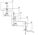
オゾン生成器30は、内部に流通路32aを形成するハウジング32を備え、流通路32aには複数の電極31が配置されている。これらの電極31は、互いに平行に対向するように配置された平板形状であり、高電圧が印加される電極と接地電圧の電極とが交互に配置されている。電極31への電圧印加は、ECU40が備えるマイクロコンピュータ(マイコン41)により制御される。
The
オゾン生成器30のハウジング32には、エアポンプ30pにより送風された空気が流入する。エアポンプ30pは電動モータにより駆動され、その電動モータはマイコン41により制御される。エアポンプ30pにより送風された空気は、ハウジング32内の流通路32aに流入し、電極31間の通路である電極間通路31aを流通する。
Air blown by the
オゾン生成器30は、含オゾン空気配管26および共用配管24を介して反応容器20に接続される。すなわち、オゾン生成器30の下流側部分には含オゾン空気配管26の上流端部が接続され、含オゾン空気配管26の下流端部は共用配管24の上流端部に接続されている。共用配管24の下流端部は反応容器20の流入口20inに接続されている。反応容器20の流出口20outには供給管23の上流端部が接続されている。供給管23の下流端部は、排気通路10exのうちNOx浄化装置12の上流側部分に接続されている。
The
含オゾン空気配管26には、電磁駆動式の逆止弁26vが取り付けられている。逆止弁26vの開閉駆動はマイコン41により制御される。したがって、エアポンプ30pを駆動させて逆止弁26vを開弁駆動させると、電極間通路31aを流通した空気は、含オゾン空気配管26、共用配管24、反応容器20および供給管23を順に流通して排気通路10exへ流入することとなる。
An electromagnetically driven
加圧空気配管25の上流端部は、吸気通路10inのうちコンプレッサ11cの下流側部分に接続され、加圧空気配管25の下流端部は共用配管24の上流端部に接続されている。要するに、共用配管24の上流端部は、加圧空気配管25および含オゾン空気配管26の両方が接続するように分岐している。換言すれば、加圧空気配管25および含オゾン空気配管26は共用配管24に対して並列に接続されている。
The upstream end of the
加圧空気配管25には、電磁駆動式の調量弁25vが取り付けられている。調量弁25vの開閉駆動はマイコン41により制御される。したがって、調量弁25vを開弁駆動させると、吸気通路10inを流通する加圧空気の一部は、加圧空気配管25、共用配管24、反応容器20および供給管23を順に流通して排気通路10exへ流入することとなる。このような調量弁25vの開弁時において、逆止弁26vの作用により、加圧空気が含オゾン空気配管26を通じてオゾン生成器30およびエアポンプ30pへ流入することが防止される。
An electromagnetically driven
逆止弁26vの弁体は、全開位置と全閉位置とに切り替え制御される。一方、調量弁25vの弁体については、反応容器20へ流入させる加圧空気の流量を調整するように弁体の開度位置が制御(調量制御)される。また、逆止弁26vおよび調量弁25vの両方を同時に開弁させることのないよう、逆止弁26vおよび調量弁25vの一方を開弁させる場合には他方を閉弁させるようにマイコン41は制御する。
The valve body of the
反応容器20には、ヒータ21および噴射弁22が取り付けられており、反応容器20の内部には、流入口20inおよび流出口20outと連通する反応室20aが形成されている。ヒータ21は、通電により発熱する発熱部を有し、発熱部への通電はマイコン41により制御される。具体的には、発熱部への電力供給量をマイコン41がデューティ制御することにより、発熱量が制御される。発熱部は反応室20aに配置され、噴射弁22から反応室20aへ噴射された燃料を加熱する。反応室20aの温度は反応室温度センサ27により検出される。反応室温度センサ27は、検出した温度の情報(反応室温度)をECU40へ出力する。
A
噴射弁22は、噴孔が形成されたボデー、電気アクチュエータおよび弁体を有する。電気アクチュエータを通電オンさせると、弁体が開弁作動して噴孔から反応室20aへ燃料が噴射され、通電オフさせると弁体が閉弁作動して燃料噴射が停止される。マイコン41は、電気アクチュエータへの通電を制御することで、反応室20aへの単位時間当たりの燃料噴射量を制御する。図示しない燃料タンク内の液体燃料は、図示しない燃料ポンプにより噴射弁22へ供給される。燃料タンク内の燃料は、先述した燃焼用の燃料としても用いられており、内燃機関10の燃焼に用いる燃料と、還元剤として用いる燃料は共用される。
The
噴射弁22から反応室20aへ噴射された燃料は、発熱部に衝突し、加熱されて気化する。気化した燃料は、流入口20inから反応室20aへ流入した空気と混合される。その結果、空気中の酸素により気体燃料が部分的に酸化され、アルデヒド等の部分酸化炭化水素に改質される。このように改質された気体燃料(改質燃料)は、供給管23を通じて排気通路10exに流入する。
The fuel injected from the
さて、オゾン生成器30の電極31へ通電すると、電極31から放出された電子が、電極間通路31aの空気中に含まれる酸素分子に衝突する。すると、酸素分子からオゾンが生成される。つまり、オゾン生成器30は、放電により酸素分子をプラズマ状態にして、活性酸素としてのオゾンを生成する。したがって、オゾン生成器30への通電時には、含オゾン空気配管26を流通する空気にオゾンが含まれる。
When the
反応室20aでは以下に詳述する冷炎反応が生じている。この冷炎反応は、流入口20inから流入する空気中の酸素により気体燃料が部分的に酸化される反応である。このように部分的に酸化された燃料(改質燃料)の具体例として、燃料(炭化水素化合物)の一部がアルデヒド基(CHO)に酸化された状態の部分酸化物(例えばアルデヒド)が挙げられる。
In the
ここで、冷炎反応について図2および図3を用いて詳述する。 Here, the cold flame reaction will be described in detail with reference to FIGS.
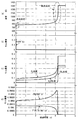
図2は、燃料(ヘキサデカン)をヒータ21に噴き付けて気化させ、気化した燃料がヒータ21近傍に滞留して改質される現象を模擬したシミュレーション結果である。具体的には、気体燃料(ヘキサデカン)を430℃に暴露した場合における、暴露開始からの経過時間に対する各種物理量の変化を示す。すなわち、図中の(a)は雰囲気温度の変化を示す。(b)は、燃料(ヘキサデカン)のモル濃度の変化を示す。(c)は、酸化で消費された酸素分子、酸化で生成された水分子および二酸化炭素分子について、各々のモル濃度の変化を示す。(d)は、冷炎反応により生成された改質燃料であるアセトアルデヒドおよびプロピオンアルデヒドのモル濃度の変化を示す。燃料噴射開始時点での初期条件は、1気圧、ヘキサデカン濃度2200ppm、酸素濃度20%、二酸化炭素濃度9%、水濃度2%である。
FIG. 2 is a simulation result simulating a phenomenon in which fuel (hexadecane) is sprayed on the
図2に示されるように、燃料を噴射すると直ぐ、雰囲気温度が上昇するとともに燃料のモル濃度が減少し、かつ、改質燃料のモル濃度が増加している。この現象は、燃料が酸素に酸化されて発熱していることと、燃料から改質燃料が生成されていることを意味する。つまり、冷炎反応が生じていることを意味する。但し、このような温度上昇や各種モル濃度の変化は一時的なものであり、燃料噴射開始から4秒ほどの期間は、温度上昇やモル濃度の変化は現れない。 As shown in FIG. 2, as soon as fuel is injected, the ambient temperature increases, the molar concentration of the fuel decreases, and the molar concentration of the reformed fuel increases. This phenomenon means that the fuel is oxidized to oxygen and generates heat, and reformed fuel is generated from the fuel. That is, a cold flame reaction is occurring. However, such a temperature rise and changes in various molar concentrations are temporary, and during the period of about 4 seconds from the start of fuel injection, no temperature rise and no change in molar concentration appear.
そして、約4秒経過した時点で、雰囲気温度がさらに上昇するとともに改質燃料のモル濃度が減少し、かつ、二酸化炭素および水の生成量と、酸素の消費量が増加している。この現象は、改質燃料が酸素に酸化されて発熱していることと、改質燃料が完全燃焼して二酸化炭素および水が生成されていることを意味する。つまり、熱炎反応が生じていることを意味する。なお、冷炎反応による温度上昇量は、熱炎反応による温度上昇量よりも小さい。また、冷炎反応による酸素消費量は、熱炎反応による酸素消費量よりも少ない。 When about 4 seconds elapse, the atmospheric temperature further rises, the reformed fuel molar concentration decreases, and the amount of carbon dioxide and water produced and the amount of oxygen consumed increase. This phenomenon means that the reformed fuel is oxidized to oxygen and generates heat, and the reformed fuel is completely burned to generate carbon dioxide and water. That is, a hot flame reaction is occurring. Note that the amount of temperature increase due to the cold flame reaction is smaller than the amount of temperature increase due to the hot flame reaction. Moreover, the oxygen consumption by a cold flame reaction is less than the oxygen consumption by a hot flame reaction.
2段階で酸化反応が生じる場合には、冷炎反応が為されてから熱炎反応が開始されるまでの期間に、改質燃料が中間生成物として現れる。中間生成物には、アルデヒドやケトン等、様々な炭化水素化合物が具体例として挙げられる。図3では、アルデヒドが生成される主要な反応経路の一例を示す。 When the oxidation reaction occurs in two stages, the reformed fuel appears as an intermediate product during the period from the start of the cold flame reaction to the start of the hot flame reaction. Specific examples of the intermediate product include various hydrocarbon compounds such as aldehydes and ketones. FIG. 3 shows an example of a main reaction route through which aldehyde is generated.
先ず、図中の(1)に示すように、炭化水素(軽油)が酸素分子と反応して炭化水素ペルオキシラジカルが生成される。この炭化水素ペルオキシラジカルは、アルデヒドと炭化水素ラジカルに分解される((2)参照)。この炭化水素ラジカルと酸素分子とが反応して別の炭化水素ペルオキシラジカルが生成される((3)参照)。この炭化水素ペルオキシラジカルは、アルデヒドと炭化水素ラジカルに分解される((4)参照)。この炭化水素ラジカルと酸素分子とが反応して別の炭化水素ペルオキシラジカルが生成される((5)参照)。このように、炭素数を減らしながら繰り返し炭化水素ペルオキシラジカルが生成され、その生成の都度、アルデヒドが生成されていく。なお、熱炎反応では、燃料が完全燃焼して二酸化炭素と水が生成され、中間生成物は現れない。すなわち、冷炎反応により生成された中間生成物は、酸化されて二酸化炭素と水になる。 First, as shown in (1) in the figure, hydrocarbon (light oil) reacts with oxygen molecules to generate hydrocarbon peroxy radicals. This hydrocarbon peroxy radical is decomposed into an aldehyde and a hydrocarbon radical (see (2)). This hydrocarbon radical reacts with oxygen molecules to generate another hydrocarbon peroxy radical (see (3)). This hydrocarbon peroxy radical is decomposed into an aldehyde and a hydrocarbon radical (see (4)). This hydrocarbon radical reacts with oxygen molecules to generate another hydrocarbon peroxy radical (see (5)). In this way, hydrocarbon peroxy radicals are repeatedly generated while reducing the number of carbon atoms, and aldehydes are generated each time the carbon peroxy radical is generated. In the hot flame reaction, the fuel is completely burned to generate carbon dioxide and water, and no intermediate product appears. That is, the intermediate product produced by the cold flame reaction is oxidized to carbon dioxide and water.
図2に示すシミュレーションでは、暴露温度を430℃としていた。これに対し、さらに本発明者らは、暴露温度を異ならせてシミュレーションによる解析を実施した。その結果、暴露温度が530℃の場合には冷炎反応で留まる期間が殆ど無く、1段で酸化反応が完了する。暴露温度を330℃にすると、430℃にした場合に比べて冷炎反応の開始時期が遅くなる。暴露温度を230℃以下にすると、冷炎反応および熱炎反応のいずれもが生じなくなり、酸化反応が生じない。 In the simulation shown in FIG. 2, the exposure temperature was 430 ° C. On the other hand, the present inventors further conducted analysis by simulation with different exposure temperatures. As a result, when the exposure temperature is 530 ° C., there is almost no period of staying in the cold flame reaction, and the oxidation reaction is completed in one stage. When the exposure temperature is set to 330 ° C., the start time of the cold flame reaction is delayed as compared with the case where the exposure temperature is set to 430 ° C. When the exposure temperature is 230 ° C. or lower, neither a cold flame reaction nor a hot flame reaction occurs, and no oxidation reaction occurs.
図2に示すシミュレーションでは、噴射した燃料と供給される空気の比率である当量比を0.23としていた。これに対し、さらに本発明者らは、当量比を異ならせてシミュレーションによる解析を実施した。なお、当量比を厳密に定義すると、「実際の混合気が含む燃料の重量」を、「完全燃焼できる燃料の重量」で除算した値である。当量比を1.0にすると、冷炎反応で留まる期間が殆ど無く、1段で酸化反応が完了する。また、当量比を0.37にすると、当量比を0.23にした場合に比べて、冷炎反応の開始時期が早くなる。また、冷炎反応速度が速くなり、冷炎反応期間が短くなる。また、冷炎反応が終了した時点での雰囲気温度が高くなる。 In the simulation shown in FIG. 2, the equivalence ratio, which is the ratio between the injected fuel and the supplied air, is 0.23. On the other hand, the present inventors further performed analysis by simulation with different equivalence ratios. If the equivalence ratio is strictly defined, it is a value obtained by dividing "the weight of fuel contained in the actual air-fuel mixture" by "the weight of fuel capable of complete combustion". When the equivalence ratio is 1.0, there is almost no period of staying in the cold flame reaction, and the oxidation reaction is completed in one stage. In addition, when the equivalent ratio is 0.37, the start time of the cold flame reaction is earlier than when the equivalent ratio is 0.23. In addition, the cold flame reaction rate is increased and the cold flame reaction period is shortened. In addition, the atmospheric temperature at the time when the cold flame reaction ends is increased.
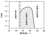
図4は、これらの解析結果をまとめて表したものである。つまり暴露温度(雰囲気温度)および当量比と、冷炎反応発生有無との関係を表しており、図4の横軸はヒータ温度(雰囲気温度)、縦軸は当量比を示す。図中のドットを付した領域は、2段酸化反応が生じる領域を表す。図示されるように、雰囲気温度が下限値よりも低い領域では、酸化反応が生じない無反応領域となる。雰囲気温度が下限値よりも高い場合であっても、当量比が1.0以上の領域であれば、1段で酸化反応が完了する1段酸化反応領域となる。 FIG. 4 summarizes these analysis results. That is, the relationship between the exposure temperature (atmosphere temperature) and the equivalence ratio and the presence / absence of the occurrence of a cold flame reaction is shown. The horizontal axis in FIG. A region with dots in the figure represents a region where a two-stage oxidation reaction occurs. As shown in the figure, in the region where the ambient temperature is lower than the lower limit value, it becomes a non-reactive region where no oxidation reaction occurs. Even if the atmospheric temperature is higher than the lower limit, if the equivalent ratio is in the region of 1.0 or more, it becomes a one-step oxidation reaction region where the oxidation reaction is completed in one step.
また、2段酸化反応領域と1段酸化反応領域との境界線は、雰囲気温度および当量比に応じて変化する。つまり、雰囲気温度が所定の温度範囲であり、かつ、当量比が所定の当量比範囲である場合に、2段酸化反応が生じる。これらの温度範囲および当量比範囲は、図4中のドットを付した領域の範囲に相当する。所定の温度範囲のうち最適温度(例えば370℃)に雰囲気温度を調整すると、上記境界線における当量比が最大値(例えば1.0)となる。したがって、冷炎反応を早期に生じさせるには、ヒータ温度を最適温度に調整し、当量比を1.0にすればよい。但し、当量比が1.0を超えると冷炎反応が生じなくなるので、1.0よりも余裕分だけ小さい値に当量比を調整することが望ましい。 Further, the boundary line between the two-stage oxidation reaction region and the first-stage oxidation reaction region varies depending on the ambient temperature and the equivalence ratio. That is, a two-stage oxidation reaction occurs when the ambient temperature is in a predetermined temperature range and the equivalent ratio is in a predetermined equivalent ratio range. These temperature range and equivalent ratio range correspond to the range of the region with dots in FIG. When the atmospheric temperature is adjusted to an optimum temperature (for example, 370 ° C.) within a predetermined temperature range, the equivalent ratio at the boundary line becomes the maximum value (for example, 1.0). Therefore, in order to cause the cold flame reaction at an early stage, the heater temperature is adjusted to the optimum temperature and the equivalence ratio is set to 1.0. However, since the cold flame reaction does not occur when the equivalent ratio exceeds 1.0, it is desirable to adjust the equivalent ratio to a value smaller than the margin by 1.0.
図2に示すシミュレーションでは、空気中のオゾン濃度をゼロにしている。これに対し、さらに本発明者らは、空気中のオゾン濃度を異ならせたシミュレーションによる解析を実施した。このシミュレーションでの初期条件は、1気圧、ヘキサデカン濃度2200ppm、雰囲気温度330℃である。その結果、オゾン濃度が大きいほど、冷炎反応の開始時期が早くなることが確認された。このようなオゾンによる現象は以下の理由により生じる。すなわち、図3中の(1)(3)(5)では、炭化水素ラジカルと酸素分子とが反応しているが、空気中にオゾンが含まれている場合にはこの反応が促進され、アルデヒドが短時間で生成されることとなる。 In the simulation shown in FIG. 2, the ozone concentration in the air is zero. On the other hand, the present inventors further performed an analysis by simulation with different ozone concentrations in the air. The initial conditions in this simulation are 1 atm, hexadecane concentration 2200 ppm, and ambient temperature 330 ° C. As a result, it was confirmed that the start time of the cold flame reaction was earlier as the ozone concentration was higher. Such a phenomenon caused by ozone occurs for the following reason. That is, in (1), (3), and (5) in FIG. 3, hydrocarbon radicals and oxygen molecules react, but when ozone is contained in the air, this reaction is promoted, and aldehyde Will be generated in a short time.
ECU40が備えるマイコン41は、プログラムを記憶する記憶装置と、記憶されたプログラムにしたがって演算処理を実行する中央演算処理装置と、を備える。ECU40は、アクセルペダル踏込量(エンジン負荷)、機関回転速度(エンジン回転数)、吸気圧、排気圧等の各種検出値に基づき、内燃機関10の作動を制御する。
The
概略、ECU40は、エンジン回転数およびエンジン負荷に応じて、図示しない燃料噴射弁から噴射される燃焼用燃料の噴射量および噴射時期を制御する。さらにECU40は、反応室温度センサ27、触媒温度センサ42および排気圧センサ43により検出された物理量に基づき、還元剤添加装置の作動を制御する。
In general, the
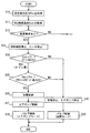
すなわち、図5および図6に示す手順のプログラムをマイコン41が所定周期で繰り返し実行することで、反応室温度に基づき改質燃料の生成とオゾンの生成を切り替える。上記プログラムは、内燃機関10の作動期間中は常時実行される。さらに、上記プログラムを実行するマイコン41は、触媒温度および排気圧に基づき、エアポンプモードと過給機モードとを切り替えるように制御する。
That is, the
エアポンプモードとは、含オゾン空気配管26を通じて、エアポンプ30pから送風される空気を反応室20aへ供給するモードである。エアポンプモードでは、オゾン生成器30により生成されたオゾンを含んだ含オゾン空気をエアポンプ30pで供給する場合と、オゾン生成器30を停止させてオゾンを含まない空気をエアポンプ30pで供給する場合がある。過給機モードとは、加圧空気配管25を通じて、コンプレッサ11cで加圧された吸気(加圧空気)の一部を反応室20aへ供給するモードである。
The air pump mode is a mode in which air blown from the
調量弁25vおよび逆止弁26vは、エアポンプモードおよび過給機モードを切り替える切替装置を提供する。調量弁25vおよび逆止弁26vの作動を制御している時のマイコン41は、切替装置による切替作動を制御する切替制御手段41a(図1参照)を提供する。なお、触媒温度センサ42は、NOx浄化装置12に取り付けられ、還元触媒の雰囲気温度(触媒温度)を検出する。排気圧センサ43は、排気管に取り付けられ、排気通路10exのうち供給管23が接続される部分での排気の圧力(排気圧)を検出する。
The
先ず、図5のステップS10において、排気圧センサ43により検出された排気管内の圧力(排気圧Pex)を取得する。続くステップS11では、触媒温度センサ42により検出された還元触媒の温度(触媒温度Tcat)を取得する。続くステップS12では、吸着要求が生じているか否かを判定する。具体的には、取得した触媒温度Tcatが、還元触媒の活性化温度(例えば200℃)よりも低い場合、吸着要求ありと判定する。但し、NOx吸着量が飽和状態になっていると推定された場合には、触媒温度Tcatが活性化温度未満であっても吸着要求なしと判定する。NOx吸着量は、内燃機関10の運転状態とその時の触媒温度Tcatの推移の履歴に基づき推定される。
First, in step S10 of FIG. 5, the pressure in the exhaust pipe (exhaust pressure Pex) detected by the
ステップS12で吸着要求ありと判定された場合には、続くステップS13において、噴射弁22およびヒータ21への通電を停止させる。これにより、噴射弁22による反応室20aへの燃料噴射が停止されるとともに、ヒータ21による反応室20aの加熱が停止される。
If it is determined in step S12 that there is an adsorption request, energization of the
続くステップS14では、NOxを還元触媒に吸着させるにあたり、供給管23から排気通路10exへオゾンを添加させる要求が生じているか否かを判定する。具体的には、取得した触媒温度Tcatが所定の第1温度T1未満であるか否かを判定する。第1温度T1は、触媒の酸化活性が生じる温度(例えば200℃)よりも低い温度に設定されている。触媒温度Tcatが所定の第1温度T1未満である場合、オゾン要求ありと判定する。
In the subsequent step S14, it is determined whether or not there is a request for adding ozone from the
要するに、第1温度以上であれば、触媒の酸化活性によりNOがNO2に酸化されるため、オゾンを添加せずとも十分にNOx(つまりNO2)を吸着できる。これに対し、触媒温度Tcatが第1温度未満であれば、オゾンを添加して排気中のNOをNO2に酸化させることで、十分に吸着できるように図ることが要求される。 In short, when the temperature is equal to or higher than the first temperature, NO is oxidized to NO 2 by the oxidation activity of the catalyst, so that NOx (that is, NO 2 ) can be sufficiently adsorbed without adding ozone. In contrast, if the catalyst temperature Tcat is lower than the first temperature, by the addition of ozone oxidizes NO in the exhaust to NO 2, is required to achieve it possible sufficiently adsorbed.
ステップS14にてオゾン要求ありと判定された場合には、続くステップS15において、エアポンプ30pの空気吐出圧(エアポンプ吐出圧)が排気圧Pexに対して十分に大きく、排気通路10exへ含オゾン空気を添加できるか否かを判定する。具体的には、ステップS10で取得した排気圧Pexが、所定の閾値Pth未満であるか否かを判定する。閾値Pthは、エアポンプ30pによる最大吐出圧、または最大吐出圧よりも僅かに小さい値に設定されている。
If it is determined in step S14 that ozone is required, in subsequent step S15, the air discharge pressure (air pump discharge pressure) of the
ステップS15により排気圧Pexが閾値Pth未満と判定された場合、つまりエアポンプ吐出圧で添加可能であると判定された場合、続くステップS16にて放電制御を実施してオゾンを生成する。具体的には、予め設定されている電力量でオゾン生成器30の電極31へ通電して放電を生じさせる。続くステップS17ではエアポンプ制御を実施して、オゾン生成器30へ空気を送風する。具体的には、予め設定されている電力量でエアポンプ30pを作動させる。続くステップS18では、調量弁25vおよび逆止弁26vをエアポンプモードで制御(バルブ制御)する。具体的には、調量弁25vを閉弁作動させ、逆止弁26vを開弁作動させる。
When it is determined in step S15 that the exhaust pressure Pex is less than the threshold value Pth, that is, when it is determined that addition is possible with the air pump discharge pressure, discharge control is performed in subsequent step S16 to generate ozone. Specifically, electricity is supplied to the
以上のステップS16、S17、S18の作動によるエアポンプモードによれば、オゾン生成器30でオゾンが生成される。そして、生成されたオゾンを含む含オゾン空気が、含オゾン空気配管26、共用配管24、反応容器20および供給管23を順に流通して排気通路10exへ添加される。よって、排気中のNOが酸化されてNO2に変化することがオゾンにより促進されるので、還元触媒へのNOx吸着量を増大できる。
According to the air pump mode by the operations of steps S16, S17, and S18 described above, ozone is generated by the
なお、ヒータ21への通電を実施していると、オゾンは加熱されて崩壊する。また、燃料噴射を実施していると、オゾンは燃料と反応してしまう。これらの点を鑑み、ステップS14にてオゾン要求ありと判定されてエアポンプモードで作動している場合には、ステップS13にてヒータ21による加熱および燃料噴射を停止させるので、オゾンが燃料と反応することや加熱崩壊が回避される。よって、生成したオゾンがそのまま排気通路10exへ添加されることとなる。
Note that when the
一方、ステップS15にて排気圧Pexが閾値Pth以上と判定された場合、つまりエアポンプ吐出圧では添加できないと判定された場合、或いはステップS14にてオゾン要求なしと判定された場合には、次のステップS19の処理を実行する。ステップS19では、オゾン生成器30およびエアポンプ30pへの通電を停止させる。続くステップS20では、調量弁25vおよび逆止弁26vを全閉モードで制御(バルブ制御)する。具体的には、調量弁25vおよび逆止弁26vを共に閉弁作動させる。
On the other hand, if it is determined in step S15 that the exhaust pressure Pex is equal to or higher than the threshold value Pth, that is, if it is determined that addition is not possible with the air pump discharge pressure, or if it is determined in step S14 that there is no ozone request, The process of step S19 is executed. In step S19, energization to the
以上のステップS19、S20の作動による全閉モードによれば、オゾン生成器30でのオゾン生成が停止され、エアポンプ30pによる空気の送風も停止される。また、加圧空気配管25からの加圧空気の供給も停止される。つまり、供給管23から排気通路10exへは、オゾンも空気も燃料も添加されない。
According to the fully closed mode by the operation of steps S19 and S20 described above, ozone generation in the
ステップS14にて触媒温度Tcatが第1温度T1以上であると判定されて、ステップS19、S20による全閉モードを実行した場合においては、不必要なオゾンの供給を回避できる。よって、オゾン生成器30およびエアポンプ30pを停止させることによる省電費を図ることができる。
When it is determined in step S14 that the catalyst temperature Tcat is equal to or higher than the first temperature T1 and the fully closed mode in steps S19 and S20 is executed, unnecessary supply of ozone can be avoided. Therefore, it is possible to save electricity by stopping the
ステップS15にて排気圧Pexが閾値Pth以上と判定されて、ステップS19、S20による全閉モードを実行した場合においては、排気通路10ex中の排気が、含オゾン空気配管26を逆流することを回避できる。よって、オゾン生成器30およびエアポンプ30pが排気で汚染されることを回避できる。
When the exhaust pressure Pex is determined to be greater than or equal to the threshold value Pth in step S15 and the fully closed mode in steps S19 and S20 is executed, the exhaust in the exhaust passage 10ex is prevented from flowing back through the ozone-containing
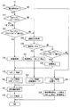
次に、ステップS12にて吸着要求なしと判定された場合の処理について、図6を用いて説明する。 Next, the processing when it is determined in step S12 that there is no suction request will be described with reference to FIG.
先ず、図6のステップS21において、還元要求が生じているか否かを判定する。具体的には、ステップS11で取得した触媒温度Tcatが、還元触媒の活性化温度以上、かつ上限温度未満である場合に、還元要求ありと判定する。触媒温度Tcatが活性化温度以上であっても上限温度以上であれば、還元剤を添加しても還元反応が殆ど生じなくなるからである。 First, in step S21 of FIG. 6, it is determined whether or not a reduction request has occurred. Specifically, when the catalyst temperature Tcat acquired in step S11 is equal to or higher than the activation temperature of the reduction catalyst and lower than the upper limit temperature, it is determined that there is a reduction request. This is because even if the catalyst temperature Tcat is equal to or higher than the activation temperature and is equal to or higher than the upper limit temperature, the reduction reaction hardly occurs even if the reducing agent is added.
ステップS21で還元要求ありと判定された場合には、続くステップS22において、還元剤でNOxを還元させるにあたり、反応室20aへオゾンを供給させる要求が生じているか否かを判定する。具体的には、触媒温度Tcatが所定の第2温度T2未満であるか否かを判定する。第2温度T2は、活性化温度よりも高い温度(例えば300℃)に設定されている。触媒温度Tcatが所定の第2温度T2未満である場合、オゾン要求ありと判定する。
If it is determined in step S21 that there is a reduction request, it is determined in subsequent step S22 whether or not there is a request to supply ozone to the
要するに、触媒温度Tcatが第2温度T2未満であれば、オゾンを供給することにより反応室20aで生じる図3の反応速度が速くなり、燃料の改質が促進される。しかし、触媒温度Tcatが第2温度T2以上であれば、オゾンを供給しなくても反応速度が十分に速くなるので、オゾンを供給することによる改質促進の効果が小さくなる。この点を鑑み、ステップS22では触媒温度Tcatが第2温度T2未満である場合にオゾン要求ありと判定するので、第2温度T2以上である場合に無駄にオゾンを供給することを回避でき、オゾン生成器30での消費電力を低減できる。
In short, when the catalyst temperature Tcat is lower than the second temperature T2, the reaction rate of FIG. 3 generated in the
ステップS22にてオゾン要求ありと判定された場合には、続くステップS23において、エアポンプ30pの空気吐出圧(エアポンプ吐出圧)が排気圧Pexに対して十分に大きく、排気通路10exへ改質還元剤を添加できるか否かを判定する。具体的には、ステップS15と同様にして、排気圧Pexが閾値Pth未満であるか否かを判定する。
If it is determined in step S22 that ozone is required, in the subsequent step S23, the air discharge pressure (air pump discharge pressure) of the
ステップS23により排気圧Pexが閾値Pth未満と判定された場合、つまりエアポンプ吐出圧で添加可能であると判定された場合、続くステップS24にて放電制御を実施してオゾンを生成する。具体的には、後述するステップS27で設定される燃料噴射量に応じたオゾン生成量となるよう、電極31への供給電力を調整する。
When it is determined in step S23 that the exhaust pressure Pex is less than the threshold value Pth, that is, when it is determined that addition is possible with the air pump discharge pressure, discharge control is performed in subsequent step S24 to generate ozone. Specifically, the power supplied to the
続くステップS25ではエアポンプ制御を実施して、オゾン生成器30へ空気を送風する。具体的には、ステップS27で噴射される燃料と供給される空気の比率である当量比が、後述する目標当量比φtrgとなるよう、エアポンプ30pへの供給電力を調整して空気送風量を調整する。続くステップS26では、調量弁25vおよび逆止弁26vをエアポンプモードで制御(バルブ制御)する。具体的には、調量弁25vを閉弁作動させ、逆止弁26vを開弁作動させる。
In subsequent step S25, air pump control is performed, and air is blown to the
続くステップS27では、NOx浄化装置12へ流入したNOxの全てを還元するにあたり、過不足なくNOx浄化装置12へ供給するための還元剤添加量を、目標燃料量Ftrgとして設定する。上記目標燃料量Ftrgとは、単位時間当たりにNOx浄化装置12へ供給する燃料の質量である。
In the subsequent step S27, when all of the NOx flowing into the
具体的には、以下に説明するNOx流入量および触媒温度Tcatに基づき、目標燃料量Ftrgを設定する。上記NOx流入量とは、単位時間当たりにNOx浄化装置12へ流入するNOxの質量である。例えば、内燃機関10の運転状態に基づき、NOx流入量を推定できる。そして、NOx流入量が多いほど、目標燃料量Ftrgを増大させる。また、NOx触媒温度に応じて還元触媒上でNOxが還元される量(還元力)が異なってくるので、NOx触媒温度による還元力の違いに応じて目標燃料量Ftrgを設定する。そして、設定した目標燃料量Ftrgに基づき、噴射弁22の作動を制御して燃料噴射を実施する。具体的には、目標燃料量Ftrgが多いほど噴射弁22の開弁時間を長くする。或いは、今回の噴射終了から次回の噴射開始までのインターバルを短くする。
Specifically, the target fuel amount Ftrg is set based on the NOx inflow amount and the catalyst temperature Tcat described below. The NOx inflow amount is the mass of NOx flowing into the
さらにステップS27では、ステップS25のエアポンプ制御で用いる目標当量比φtrgを、反応室温度センサ27により検出された反応室温度および目標燃料量Ftrgに基づき、冷炎反応を生じさせるように設定する。具体的には、2段酸化反応領域における当量比の最大値であって、雰囲気温度に対応する当量比の最大値、またはその最大値から所定の余裕分だけ減算した値を、目標当量比φtrgとしてマップ化してマイコン41に記憶させておく。検出された反応室温度に対応する目標当量比φtrgを、マップを参照して算出する。上述の如く余裕分を見込んで目標当量比φtrgを設定することにより、実際の当量比が目標当量比φtrgより大きくなったとしても、上記当量比の最大値を超えるおそれを低減でき、冷炎反応にとどまらず熱炎反応にまで至るおそれを低減できる。
In step S27, the target equivalence ratio φtrg used in the air pump control in step S25 is set based on the reaction chamber temperature and the target fuel amount Ftrg detected by the reaction
続くステップS28では、取得した反応室温度が、予め設定しておいた目標温度Ttrgと一致するよう、ヒータ21をフィードバック制御する。例えば、ヒータ21への電力供給量を、反応室温度センサ27による検出値と目標温度Ttrgとの差分に応じてデューティ制御する。或いは、反応室温度が目標温度Ttrgよりも所定以上高くなった場合にヒータ21への電力供給量を停止させるといったオンオフ制御を実行する。目標温度Ttrgは、図4に示す2段酸化反応領域のうち、当量比が最大となる雰囲気温度(例えば370℃)に設定されている。
In the subsequent step S28, the
以上のステップS24、S25、S26、S27、S28の作動によるエアポンプモードによれば、オゾン生成器30でオゾンが生成される。そして、生成されたオゾンを含む含オゾン空気が、含オゾン空気配管26および共用配管24を流通して反応容器20へ供給される。よって、反応容器20での燃料の改質がオゾンにより促進されるので、還元触媒でのNOx浄化率を向上できる。
According to the air pump mode by the operations of the above steps S24, S25, S26, S27, and S28, ozone is generated by the
また、上述のごとく目標燃料量Ftrgに応じてエアポンプ30pおよびヒータ21を制御することにより、反応室温度および当量比は、2段酸化反応領域に調整される。よって、冷炎反応を生じさせて先述した改質燃料が生成される。反応室温度が調整される温度範囲の下限は、1段酸化領域および2段酸化領域と無反応領域との境界線となる260℃である。上記温度範囲の上限は、1段酸化領域と2段酸化領域の境界線のうちの最大温度である。当量比が調整される範囲の上限は、1段酸化領域と2段酸化領域の境界線のうちの最大値であって、370℃に対応する当量比である。
Further, by controlling the
一方、ステップS23にて排気圧Pexが閾値Pth以上と判定された場合、つまりエアポンプ吐出圧では添加できないと判定された場合、或いはステップS22にてオゾン要求なしと判定された場合には、次のステップS29の処理を実行する。ステップS29では、コンプレッサ11cにより圧縮された加圧空気の圧力(過給圧)を取得する。例えば、エンジン回転数やエンジン負荷等の内燃機関10の運転状態に基づき、過給圧を推定する。続くステップS30では、取得した過給圧が、ステップS10で取得した排気圧Pexより大きいか否かを判定する。
On the other hand, if it is determined in step S23 that the exhaust pressure Pex is equal to or higher than the threshold value Pth, that is, if it is determined that addition is not possible with the air pump discharge pressure, or if it is determined in step S22 that there is no ozone request, The process of step S29 is executed. In step S29, the pressure (supercharging pressure) of the compressed air compressed by the
過給圧が排気圧Pexより大きいと判定された場合には、次のステップS31において、オゾン生成器30およびエアポンプ30pへの通電を停止させる。続くステップS32では、調量弁25vおよび逆止弁26vを過給機モードで制御(バルブ制御)する。具体的には、調量弁25vを開弁作動させ、逆止弁26vを閉弁作動させる。次に、先述したステップS27による燃料噴射制御、およびステップS28によるヒータ制御を実行する。
When it is determined that the supercharging pressure is higher than the exhaust pressure Pex, energization to the
以上のステップS32、S27、S28の作動による過給機モードによれば、コンプレッサ11cによる加圧空気が、加圧空気配管25および共用配管24を流通して反応室20aへ供給される。つまり、燃料の部分酸化反応に必要な酸素が反応室20aへ供給される。そして、排気圧Pexが閾値Pth以上であるにも拘らず、加圧空気の圧力で、改質燃料が排気通路10exへ添加される。このように、改質燃料がNOx浄化装置12へ流入するので、未改質の燃料を添加する場合に比べれば、還元触媒でのNOx浄化率を向上できる。
According to the supercharger mode by the operation of steps S32, S27, and S28 described above, the pressurized air from the
一方、ステップS30にて過給圧が排気圧Pex以下であると判定された場合、つまり加圧空気に係る過給圧では改質燃料を排気通路10exに添加できないと判定された場合、次のステップS33においてステップS15と同様の判定を実行する。すなわち、エアポンプ吐出圧が排気圧Pexに対して十分に大きく、排気通路10exへ含オゾン空気を添加できるか否かを判定する。排気圧Pexが閾値Pth未満と判定された場合、つまりエアポンプ吐出圧で添加可能であると判定された場合、続くステップS34にてオゾン生成器30への通電を停止させる。その後、先述したステップS25によるエアポンプ制御、ステップS26によるエアポンプモードでのバルブ制御、ステップS27による燃料噴射制御、およびステップS28によるヒータ制御を実行する。
On the other hand, when it is determined in step S30 that the supercharging pressure is equal to or lower than the exhaust pressure Pex, that is, when it is determined that the reformed fuel cannot be added to the exhaust passage 10ex with the supercharging pressure related to the pressurized air, In step S33, the same determination as in step S15 is executed. That is, it is determined whether or not the air pump discharge pressure is sufficiently larger than the exhaust pressure Pex and ozone-containing air can be added to the exhaust passage 10ex. When it is determined that the exhaust pressure Pex is less than the threshold value Pth, that is, when it is determined that addition is possible with the air pump discharge pressure, energization to the
なお、上述の如く排気圧Pexが過給圧以上(S30:NO)かつ閾値Pth未満である状態は、例えば次の状況で生じうる。すなわち、排気圧Pexの上昇に伴い生じる過給圧の上昇にはタイムラグがある。そのため、排気圧Pexが低圧の状態から上昇する際に、上記状態が生じうる。 Note that, as described above, the state where the exhaust pressure Pex is equal to or higher than the supercharging pressure (S30: NO) and lower than the threshold value Pth can occur in the following situation, for example. That is, there is a time lag in the increase in the supercharging pressure that occurs as the exhaust pressure Pex increases. Therefore, when the exhaust pressure Pex rises from the low pressure state, the above state can occur.
以上のステップS25、S26、S27、S28の作動によるエアポンプモードによれば、オゾンを含まない空気が、含オゾン空気配管26および共用配管24を流通して反応容器20へ供給される。つまり、燃料の部分酸化反応に必要な酸素が反応室20aへ供給される。そして、過給圧が排気圧Pex以下であるにも拘らず、エアポンプ30pの送風圧力で、改質燃料が排気通路10exへ添加される。このように、改質燃料がNOx浄化装置12へ流入するので、未改質の燃料を添加する場合に比べれば、還元触媒でのNOx浄化率を向上できる。
According to the air pump mode by the operations of the above steps S25, S26, S27, and S28, air not containing ozone is supplied to the
一方、ステップS33において排気圧Pexが閾値Pth以上であると判定された場合、つまり加給圧で添加できないのみならず、エアポンプ30pの送風圧力でも添加できないと判定された場合、NOx浄化装置12の作動を停止させる。具体的には、次のステップS35において、ステップS20と同様にして調量弁25vおよび逆止弁26vを全閉モードで制御(バルブ制御)する。続くステップS36では、オゾン生成器30、エアポンプ30p、ヒータ21および噴射弁22への通電を停止させる。
On the other hand, if it is determined in step S33 that the exhaust pressure Pex is greater than or equal to the threshold value Pth, that is, if it is determined that not only the supply pressure cannot be added but also the blowing pressure of the
要するに、還元要求があると判定された場合(S21:YES)であっても、エアポンプ30pの送風圧力および過給圧のいずれもが排気圧Pexより低圧である場合(S33:NO)には、全閉モードにしてNOx浄化装置12の作動を停止させる。また、吸着要求がなく(S12:NO)、還元要求がないと判定された場合(S21:NO)においても、全閉モードでNOx浄化装置12の作動を停止させる。吸着要求および還元要求がない場面の具体例として、NOx触媒温度が活性化温度未満であり、かつ、NOx吸着量が飽和状態になっている場面や、NOx触媒温度が還元可能範囲を超えて高温になっている場面が挙げられる。
In short, even if it is determined that there is a reduction request (S21: YES), if both the blowing pressure and supercharging pressure of the
また、触媒温度Tcatが活性化温度未満であり、かつ、NOx吸着量が飽和状態になっている場合や、触媒温度Tcatが還元可能範囲を超えて高温になっている場合にも、全閉モードでのNOx浄化装置12の作動停止が為されることとなる。
Further, when the catalyst temperature Tcat is lower than the activation temperature and the NOx adsorption amount is saturated, or when the catalyst temperature Tcat is higher than the reducible range, the fully closed mode Thus, the operation of the
以上により、本実施形態に係る還元剤添加装置は、反応容器20と、オゾン生成器30と、エアポンプ30pと、含オゾン空気配管26と、加圧空気配管25と、調量弁25vおよび逆止弁26vから構成される切替装置と、切替制御手段41aと、を備える。つまり、含オゾン空気を反応室20aへ導く含オゾン空気配管26と、加圧空気を反応室20aへ導く加圧空気配管25とを別々に備える。そして、エアポンプ30pおよびオゾン生成器30は、含オゾン空気配管26の経路に配置され、加圧空気配管25の経路からは隔離されることとなる。
As described above, the reducing agent addition apparatus according to this embodiment includes the
そのため、エアポンプ30pのインペラやインペラケース、オゾン生成器30の電極31等が、吸気に含まれる汚物で汚染されることを抑制できる。汚物の具体例としては、内燃機関10の吸気に含まれる潤滑オイルの成分や未燃焼の燃料成分等が挙げられる。特に本実施形態では、含オゾン空気配管26のうち、オゾン生成器30およびエアポンプ30pの下流側部分に逆止弁26vが設けられている。この逆止弁26vは、オゾン生成器30およびエアポンプ30pへ加圧空気が流入することを防止する流入防止手段を提供する。そのため、オゾン生成器30およびエアポンプ30pが吸気により汚染されることの回避の確実性を向上できる。
Therefore, it can suppress that the impeller and impeller case of the
また、本実施形態では上述した切替装置および切替制御手段を備えるため、排気圧Pexが高くエアポンプ30pでは添加困難な場合(S23:NO)には、過給機モードに切り替える(S32)。よって、上記の場合であっても反応室20aで改質された還元剤を添加できる。また、エアポンプ30pでの添加が可能な程度に排気圧Pexが低く(S23:YES)、かつ、オゾンによるNOx浄化率向上が見込めるような還元触媒温度である場合(S22:YES)には、エアポンプモードに切り替える(S26)。よって、上記の場合には含オゾン空気で改質された還元剤を添加できる。
Further, in the present embodiment, since the switching device and the switching control means described above are provided, when the exhaust pressure Pex is high and it is difficult to add by the
以上により、本実施形態によれば、オゾンによるNOx浄化率向上を図ることができ、それでいて、排気圧Pexが高くても改質還元剤の添加を可能にすることを、エアポンプ30pおよびオゾン生成器30の汚染を抑制しつつ実現できる。
As described above, according to the present embodiment, it is possible to improve the NOx purification rate by ozone, and to enable the addition of the reforming reducing agent even when the exhaust pressure Pex is high, the
ここで、先述した特許文献2に記載の還元剤添加装置では、過給機で加圧された吸気をエアポンプでアシストして添加している。つまり、本実施形態に係る含オゾン空気配管26を備えておらず、加圧空気配管25にエアポンプを設けている。そのため、内燃機関の低負荷運転時には過給圧が低くなり、エアポンプに負荷をかける懸念が生じる。これに対し本実施形態では、含オゾン空気配管26と加圧空気配管25とを別々に備えるので、上記懸念を解消できる。
Here, in the reducing agent addition apparatus described in
また、加圧空気配管25には調量弁25vが設けられており、エアポンプモード時には調量弁25vを閉弁作動させるので、過給圧が低い場合であっても、エアポンプ30pによる送風空気や排気が加圧空気配管25に逆流することを防止できる。
The
さらに、本実施形態に係る還元剤添加装置は、還元可否判定手段と、還元時オゾン要否判定手段と、還元時エアポンプ可否判定手段と、を備える。還元可否判定手段は、ステップS21の処理を実行しているマイコン41により提供され、触媒温度Tcatに基づき、還元触媒上でのNOxの還元が可能な還元可能状態であるか否かを判定する。還元時オゾン要否判定手段は、ステップS22の処理を実行しているマイコン41により提供され、触媒温度Tcatに基づき、還元可能状態である時に含オゾン空気を反応室20aへ供給する必要がある還元時オゾン要求状態であるか否かを判定する。還元時エアポンプ可否判定手段は、ステップS23の処理を実行しているマイコン41により提供され、排気圧Pexに基づき、エアポンプ30pによる還元剤の排気通路10exへの添加が可能な還元時低排圧状態であるか否かを判定する。切替制御手段41aは、還元可能状態(S21:YES)、かつ還元時オゾン要求状態(S22:YES)、かつ還元時低排圧状態(S23:YES)と判定されていることに基づき、エアポンプモードに切り替える。
Furthermore, the reducing agent addition apparatus according to the present embodiment includes a reduction possibility determination unit, a reduction ozone necessity determination unit, and a reduction air pump availability determination unit. The reduction possibility determination means is provided by the
これにより、エアポンプ30pで添加できる程度に排気圧Pexが低ければ、エアポンプモードに切り替えて含オゾン空気を反応室20aへ供給できるので、改質還元剤の活性化を促進でき、NOx浄化率向上を図ることができる。
Thus, if the exhaust pressure Pex is low enough to be added by the
さらに、本実施形態に係る切替制御手段41aは、還元可能状態(S21:YES)、かつ還元時オゾン要求状態(S22:YES)、かつ還元時低排圧状態でない(S23:NO)と判定されていることに基づき、過給機モードに切り替える。 Furthermore, the switching control means 41a according to the present embodiment is determined to be in the reducible state (S21: YES), the ozone request state during reduction (S22: YES), and not in the low exhaust pressure state during reduction (S23: NO). Switch to supercharger mode.
これにより、エアポンプ30pでは添加できない程度に排気圧Pexが高くても、過給機モードに切り替えることで、オゾンの効果は得られないものの改質還元剤を排気通路10exに添加できる。よって、改質還元剤を添加できない事態に陥る機会を低減できる。
Thereby, even if the exhaust pressure Pex is so high that it cannot be added by the
さらに、本実施形態に係る切替制御手段41aは、還元可能状態(S21:YES)、かつ還元時オゾン要求状態でない(S22:NO)と判定されていることに基づき、過給機モードに切り替える。 Furthermore, the switching control means 41a according to the present embodiment switches to the supercharger mode based on the determination that it is in the reducible state (S21: YES) and is not in the reducing ozone request state (S22: NO).
これにより、エアポンプ30pでは添加できない程度に排気圧Pexが高くても、過給機モードに切り替えることで、改質還元剤を排気通路10exに添加できる。よって、改質還元剤を添加できない事態に陥る機会を低減できる。なお、排気圧Pexが高い場合には、内燃機関10の高負荷運転に伴い排気温度が高く、還元時オゾン要求状態にならない程度に触媒温度Tcatが高くなっていることが多い。
Thereby, even if the exhaust pressure Pex is so high that it cannot be added by the
また、本実施形態に係る過給機モードでは、エアポンプ30pおよびオゾン生成器30への通電を停止させるので、エアポンプ30pおよびオゾン生成器30での消費電力を低減できる。
Further, in the supercharger mode according to the present embodiment, since the energization to the
さらに、本実施形態に係る還元剤添加装置は、吸着可否判定手段と、吸着時オゾン要否判定手段と、吸着時エアポンプ可否判定手段と、を備える。吸着可否判定手段は、ステップS12の処理を実行しているマイコン41により提供され、触媒温度Tcatに基づき、還元触媒へのNOxの吸着が可能な吸着可能状態であるか否かを判定する。吸着時オゾン要否判定手段は、ステップS14の処理を実行しているマイコン41により提供され、触媒温度Tcatに基づき、吸着可能状態である時に含オゾン空気の添加が要求される吸着時オゾン要求状態であるか否かを判定する。吸着時エアポンプ可否判定手段は、ステップS15の処理を実行しているマイコン41により提供され、排気圧力に基づき、エアポンプ30pによる含オゾン空気の排気通路10exへの添加が可能な吸着時低排圧状態であるか否かを判定する。切替制御手段41aは、吸着可能状態(S12:YES)、かつ吸着時オゾン要求状態(S14:YES)、かつ吸着時低排圧状態(S15:YES)と判定されていることに基づき、エアポンプモードに切り替える。
Furthermore, the reducing agent addition apparatus according to the present embodiment includes an adsorption availability determination unit, an adsorption ozone necessity determination unit, and an adsorption air pump availability determination unit. The adsorbability determination means is provided by the
これにより、エアポンプ30pで添加できる程度に排気圧Pexが低ければ、エアポンプモードに切り替えてオゾンを排気通路10exへ添加できるので、排気中のNOをNO2に酸化させることを促進でき、還元触媒にNOxを吸着させることを促進できる。よって、還元触媒で吸着されずに大気に放出されてしまうNOx量を低減でき、ひいてはNOx浄化率を向上できる。
Accordingly, if the exhaust pressure Pex is low enough to be added by the
さらに本実施形態では、還元触媒は少なくとも銀を含む物質である。具体的には、担体にコーティングされたアルミナ上に銀触媒が担持されている。このように銀触媒を採用することで、例えば白金触媒を採用した場合に比べて図3の部分酸化反応が生じやすくなる。よって、銀触媒を採用する本実施形態によれば、白金触媒を採用した場合に比べてNOx浄化率を向上できる。特に、触媒温度Tcatが活性化している温度領域のうち、低温の領域において、NOx浄化率向上の効果が顕著に発揮されるようになる。 Furthermore, in this embodiment, the reduction catalyst is a substance containing at least silver. Specifically, a silver catalyst is supported on alumina coated on a carrier. By employing a silver catalyst in this way, the partial oxidation reaction of FIG. 3 is more likely to occur than when a platinum catalyst is employed, for example. Therefore, according to this embodiment that employs a silver catalyst, the NOx purification rate can be improved as compared with the case where a platinum catalyst is employed. In particular, the effect of improving the NOx purification rate is remarkably exhibited in the low temperature region of the temperature region where the catalyst temperature Tcat is activated.
さらに本実施形態では、改質手段は、還元剤を加熱するヒータ21(加熱手段)を有し、加熱手段により所定温度以上に加熱された還元剤を、空気中に含まれる酸素により部分的に酸化させて改質することを特徴とする。これによれば、燃料が部分酸化することを容易に実現でき、還元剤の改質を容易に実現できる。また、ヒータ21で燃料を加熱することにより、炭素数の少ない炭化水素化合物に燃料を分解させるクラッキングが生じるようになる。そして、クラッキングにより炭素数が少なくなった炭化水素は沸点が低くなるので、気化した燃料が液体に戻ることが抑制される。
Furthermore, in the present embodiment, the reforming means has a heater 21 (heating means) for heating the reducing agent, and the reducing agent heated to a predetermined temperature or higher by the heating means is partially due to oxygen contained in the air. It is characterized by being modified by oxidation. According to this, partial oxidation of the fuel can be easily realized, and reforming of the reducing agent can be easily realized. Further, by heating the fuel with the
さらに本実施形態では、オゾン生成器30を備え、冷炎反応を生じさせる時には、オゾン生成器30により生成されたオゾンを供給する。そのため、冷炎反応の開始時期の早期化と、冷炎反応時間の短縮化を図ることができる。よって、反応室20aでの燃料の滞留時間が短くなるように反応容器20を小型化しても、上記滞留時間内に冷炎反応が完了するようにできる。よって、反応容器20の小型化を図ることができる。
Furthermore, in this embodiment, the
さらに本実施形態では、触媒温度Tcatが活性化温度よりも低温の場合には、噴射弁22による燃料噴射を停止させつつ、オゾン生成器30により生成されたオゾンを空気通路23bへ供給させることで、排気通路10exへオゾンを添加する。これによれば、NOx浄化装置12の還元触媒が活性化していないにも拘わらず還元剤を添加することを防止できる。そして、オゾンの添加により、排気中のNOをNO2に酸化させてNOx浄化触媒に吸着させるので、NOx浄化装置12へのNOx吸着量を増大できる。
Furthermore, in this embodiment, when the catalyst temperature Tcat is lower than the activation temperature, the ozone generated by the
(他の実施形態)
以上、発明の好ましい実施形態について説明したが、発明は上述した実施形態に何ら制限されることなく、以下に例示するように種々変形して実施することが可能である。各実施形態で具体的に組合せが可能であることを明示している部分同士の組合せばかりではなく、特に組合せに支障が生じなければ、明示してなくとも実施形態同士を部分的に組み合せることも可能である。
(Other embodiments)
The preferred embodiments of the present invention have been described above, but the present invention is not limited to the above-described embodiments, and various modifications can be made as illustrated below. Not only combinations of parts that clearly show that combinations are possible in each embodiment, but also combinations of the embodiments even if they are not explicitly stated unless there is a problem with the combination. Is also possible.
図1に示す実施形態では、排気圧センサ43を備え、排気通路10exの圧力である排気圧Pexを直接検出している。これに対し、排気圧センサ43を廃止して、例えば内燃機関10の運転状態やDPF13での圧力損失等に基づき、排気圧Pexを推定してもよい。
In the embodiment shown in FIG. 1, the
図1に示す実施形態では、NOx浄化装置12に取り付けられた触媒温度センサ42を備え、還元触媒の雰囲気温度(触媒温度Tcat)を直接検出している。これに対し、触媒温度センサ42を廃止して、例えば内燃機関10の運転状態等に基づき、触媒温度Tcatを推定してもよい。
In the embodiment shown in FIG. 1, a
図1に示す実施形態では、エアポンプ30pを、含オゾン空気配管26のうちオゾン生成器30の上流側に配置しているが、オゾン生成器30の下流側に配置してもよい。図1に示す実施形態では、DPF13を、排気通路10exのうちNOx浄化装置12の下流側に配置しているが、NOx浄化装置12の上流側に配置してもよい。
In the embodiment shown in FIG. 1, the
図5に示す実施形態では、ステップS14の判定に用いる第1温度T1を活性化温度よりも低い値に設定しているが、第1温度T1を活性化温度に設定してもよい。 In the embodiment shown in FIG. 5, the first temperature T1 used for the determination in step S14 is set to a value lower than the activation temperature. However, the first temperature T1 may be set to the activation temperature.
図5に示す実施形態では、触媒温度Tcatに基づく吸着要求の有無判定(S12)および排気圧Pexに基づく判定(S15)に応じて、エアポンプモードおよび全閉モードを切り替えている。これに対し、排気圧Pexに拘らず、吸着要求有りの場合にはエアポンプモードに設定し、ステップS20による全閉モードを廃止してもよい。 In the embodiment shown in FIG. 5, the air pump mode and the fully closed mode are switched according to the determination of whether or not there is an adsorption request based on the catalyst temperature Tcat (S12) and the determination based on the exhaust pressure Pex (S15). On the other hand, regardless of the exhaust pressure Pex, if there is an adsorption request, the air pump mode may be set and the fully closed mode in step S20 may be abolished.
図1に示す実施形態では、電磁駆動式の逆止弁26vを採用し、逆止弁26vの開閉作動をマイコン41が電子制御している。これに対し、弁体を閉弁させる向きに弾性力を付与させ、弁体の上流側圧力が下流側圧力よりも高く、その差圧により弾性力に抗して弁体を開弁作動させる、機械式の逆止弁を採用してもよい。
In the embodiment shown in FIG. 1, an electromagnetically driven
図1に示す実施形態では、調量弁25vと逆止弁26vを別体に構成しているが、一体に構成してもよい。図1に示す実施形態では、過給機11は、排気の運動エネルギによりコンプレッサ11cを回転させているが、電動モータによりコンプレッサ11cを駆動させる過給機を採用してもよい。
In the embodiment shown in FIG. 1, the
上記実施形態では、触媒温度Tcatが活性化温度以上かつ第2温度T2未満であることを条件として、オゾンを用いた改質を実施する。これに対し、触媒温度Tcatが活性化温度以上の場合において、触媒温度Tcatが第2温度T2よりも高温の第3温度(例えば350℃)以上であれば、オゾン供給を停止させて酸素供給した状態で、加熱された燃料を部分酸化させるようにしてもよい。第3温度以上の高温であれば、オゾンを供給しなくても十分に燃料は部分酸化するので、上述の如くオゾン供給を停止させれば、オゾン生成器30における電力消費を低減できる。要するに、オゾン無しでもヒータ21により燃料を加熱して酸素と反応させれば、燃料の部分酸化は可能である。但し、オゾンを用いて改質した方が、図3の反応を促進できる。
In the above embodiment, the reforming using ozone is performed on the condition that the catalyst temperature Tcat is equal to or higher than the activation temperature and lower than the second temperature T2. On the other hand, when the catalyst temperature Tcat is equal to or higher than the activation temperature, the ozone supply is stopped and oxygen is supplied if the catalyst temperature Tcat is equal to or higher than the third temperature (for example, 350 ° C.) higher than the second temperature T2. In the state, the heated fuel may be partially oxidized. If the temperature is higher than the third temperature, the fuel is sufficiently partially oxidized without supplying ozone. Therefore, if the ozone supply is stopped as described above, power consumption in the
図1に示す吸気通路10inに、コンプレッサ11cで加圧された吸気を冷却する冷却器が備えられている場合において、加圧空気配管25を冷却器の上流側に接続して冷却前の吸気を反応容器20へ供給するように構成することが望ましい。但し、加圧空気配管25を冷却器の下流側に接続して冷却後の吸気を反応容器20へ供給するように構成してもよい。
In the case where the intake passage 10in shown in FIG. 1 is provided with a cooler that cools the intake air pressurized by the
上記実施形態では、銀を含んだ触媒を還元触媒として用いているが、本発明はこのような銀触媒に限定されるものではなく、例えば銅または鉄を含んだ触媒を還元触媒として用いてもよい。 In the above embodiment, a catalyst containing silver is used as the reduction catalyst. However, the present invention is not limited to such a silver catalyst. For example, a catalyst containing copper or iron may be used as the reduction catalyst. Good.
また、図1に示す実施形態では、NOxを物理的に捕捉(つまり吸着)する還元触媒が採用されているが、NOxを化学的結合により捕捉(つまり吸蔵)する還元触媒が採用された燃焼システムに、還元剤添加装置を適用させてもよい。このように吸蔵する還元触媒の具体例として、バリウム等のアルカリ土類金属やリチウム等のアルカリ金属を白金に組合せた触媒が挙げられる。 In the embodiment shown in FIG. 1, a reduction catalyst that physically captures (that is, adsorbs) NOx is employed, but a combustion system that employs a reduction catalyst that traps (that is, occludes) NOx by chemical bonding. Further, a reducing agent adding device may be applied. Specific examples of the reduction catalyst that occludes in this way include a catalyst in which an alkaline earth metal such as barium or an alkali metal such as lithium is combined with platinum.
上記実施形態に係る改質では、還元剤に含まれるアルデヒドの割合が所定割合(例えば10%)となるように改質している。これに対し、アルデヒドの割合がほぼ100%になるように改質してもよい。また、本発明に係る改質還元剤は、アルデヒドを含むことに限定されるものではない。例えば、アルコール、アセテート、一酸化炭素、水素を部分酸化物として用いた還元剤添加装置であってもよい。 In the modification according to the embodiment, the modification is performed so that the ratio of the aldehyde contained in the reducing agent is a predetermined ratio (for example, 10%). On the other hand, you may modify | reform so that the ratio of an aldehyde may become about 100%. Further, the modified reducing agent according to the present invention is not limited to containing an aldehyde. For example, a reducing agent addition apparatus using alcohol, acetate, carbon monoxide, or hydrogen as a partial oxide may be used.
内燃機関10が理論空燃比よりもリーンな状態で燃焼させている時に、NOx浄化装置12がNOxを吸着し、リーン燃焼以外の時にNOxを還元させる燃焼システムに、還元剤添加装置を適用させてもよい。この場合、リーン燃焼時にはオゾンを生成し、リーン燃焼以外の時に改質燃料を生成させればよい。このようにリーン燃焼時にNOxを捕捉する触媒の具体例としては、担体に担持された白金とバリウムによる吸蔵還元触媒が挙げられる。
When the
図1に示す実施形態では、車両に搭載された燃焼システムに還元剤添加装置を適用させている。これに対し、定置式の燃焼システムに還元剤添加装置を適用させてもよい。図1に示す実施形態では、圧縮自着火式のディーゼルエンジンに還元剤添加装置を適用させており、燃焼用の燃料として用いる軽油を還元剤として用いている。これに対し、点火着火式のガソリンエンジンに還元剤添加装置を適用させて、燃焼用の燃料として用いるガソリンを還元剤として用いてもよい。 In the embodiment shown in FIG. 1, a reducing agent addition device is applied to a combustion system mounted on a vehicle. On the other hand, a reducing agent addition device may be applied to a stationary combustion system. In the embodiment shown in FIG. 1, a reducing agent addition device is applied to a compression self-ignition diesel engine, and light oil used as a fuel for combustion is used as a reducing agent. On the other hand, gasoline used as a fuel for combustion may be used as a reducing agent by applying a reducing agent addition device to an ignition ignition type gasoline engine.
10…内燃機関、10ex…排気通路、11…過給機、12…NOx浄化装置、20a…反応室、20…反応容器、25…加圧空気配管、25v…調量弁(切替装置)、26…含オゾン空気配管、26v…逆止弁(切替装置)、30…オゾン生成器、30p…エアポンプ、41a…切替制御手段。
DESCRIPTION OF
Claims (5)
空気中の酸素により前記還元剤を酸化させる反応室(20a)を形成し、前記酸化により前記還元剤を改質させる反応容器(20)と、
空気中の酸素からオゾンを生成するオゾン生成器(30)と、
前記オゾン生成器へ空気を送風するエアポンプ(30p)と、
前記オゾン生成器により生成されたオゾンを含んだ空気である含オゾン空気を、前記反応室へ導く含オゾン空気配管(26)と、
前記過給機により加圧された空気である加圧空気の一部を、前記反応室へ導く加圧空気配管(25)と、
前記含オゾン空気を前記反応室へ供給するエアポンプモード、および前記加圧空気を前記反応室へ供給する過給機モードを切り替える切替装置(25v、26v)と、
前記還元触媒の温度である触媒温度および前記排気通路の圧力である排気圧力に基づき、前記切替装置による切替作動を制御する切替制御手段(41a)と、
を備えることを特徴とする還元剤添加装置。 A supercharger (11) that pressurizes and supplies intake air of the internal combustion engine (10), and a NOx purification device (12) that is disposed in the exhaust passage (10ex) of the internal combustion engine and purifies NOx in the exhaust gas on a reduction catalyst. And a reducing agent addition device for adding a reducing agent to the upstream side of the reduction catalyst in the exhaust passage,
A reaction chamber (20a) for oxidizing the reducing agent with oxygen in the air, and a reaction vessel (20) for modifying the reducing agent by the oxidation;
An ozone generator (30) for generating ozone from oxygen in the air;
An air pump (30p) for blowing air to the ozone generator;
Ozone-containing air piping (26) for introducing ozone-containing air, which is air containing ozone generated by the ozone generator, to the reaction chamber;
A pressurized air pipe (25) for guiding a part of the pressurized air, which is air pressurized by the supercharger, to the reaction chamber;
A switching device (25v, 26v) for switching between an air pump mode for supplying the ozone-containing air to the reaction chamber and a supercharger mode for supplying the pressurized air to the reaction chamber;
Switching control means (41a) for controlling the switching operation by the switching device based on the catalyst temperature which is the temperature of the reduction catalyst and the exhaust pressure which is the pressure of the exhaust passage;
An apparatus for adding a reducing agent, comprising:
前記触媒温度に基づき、前記還元可能状態である時に前記含オゾン空気を前記反応室へ供給する必要がある還元時オゾン要求状態であるか否かを判定する還元時オゾン要否判定手段(S22)と、
前記排気圧力に基づき、前記エアポンプによる前記還元剤の前記排気通路への添加が可能な還元時低排圧状態であるか否かを判定する還元時エアポンプ可否判定手段(S23)と、
を備え、
前記切替制御手段は、前記還元可能状態、かつ前記還元時オゾン要求状態、かつ前記還元時低排圧状態と判定されていることに基づき、前記エアポンプモードに切り替えることを特徴とする請求項1に記載の還元剤添加装置。 Reducibility determination means (S21) for determining whether or not it is a reducible state capable of reducing NOx on the reduction catalyst based on the catalyst temperature;
On-reduction ozone necessity determination means for determining whether the ozone-containing air needs to be supplied to the reaction chamber based on the catalyst temperature or not when the reduction is possible (S22) When,
A reduction-time air pump availability determination means (S23) for determining whether or not the reduction agent is in a low exhaust pressure state during reduction that allows the addition of the reducing agent to the exhaust passage by the air pump based on the exhaust pressure;
With
The switching control means switches to the air pump mode based on the determination that the reduction possible state, the reduction ozone demand state, and the reduction low exhaust pressure state are established. The reducing agent addition apparatus as described.
前記触媒温度に基づき、前記吸着可能状態である時に前記含オゾン空気の添加が要求される吸着時オゾン要求状態であるか否かを判定する吸着時オゾン要否判定手段(S14)と、
前記排気圧力に基づき、前記エアポンプによる前記含オゾン空気の前記排気通路への添加が可能な吸着時低排圧状態であるか否かを判定する吸着時エアポンプ可否判定手段(S15)と、
を備え、
前記切替制御手段は、前記吸着可能状態、かつ前記吸着時オゾン要求状態、かつ前記吸着時低排圧状態と判定されていることに基づき、前記エアポンプモードに切り替えることを特徴とする請求項1〜4のいずれか1つに記載の還元剤添加装置。 An adsorbability determination means (S12) for determining whether or not the NOx can be adsorbed on the reduction catalyst based on the catalyst temperature;
An adsorbent ozone necessity determination means (S14) for determining whether or not the adsorbed ozone is required based on the catalyst temperature when the adsorbable state is required;
An adsorbing air pump availability determination means (S15) for determining whether or not the ozone pumping air can be added to the exhaust passage by the air pump based on the exhaust pressure;
With
The switching control means switches to the air pump mode based on being determined as the adsorption possible state, the adsorption ozone demand state, and the adsorption low exhaust pressure state. 4. The reducing agent addition apparatus according to any one of 4.
Priority Applications (4)
| Application Number | Priority Date | Filing Date | Title |
|---|---|---|---|
| JP2014190155A JP6052257B2 (en) | 2014-09-18 | 2014-09-18 | Reducing agent addition device |
| EP15184973.4A EP2998532B1 (en) | 2014-09-18 | 2015-09-14 | Reducing agent supplying device |
| US14/857,181 US9488082B2 (en) | 2014-09-18 | 2015-09-17 | Reducing agent supplying device |
| CN201510599272.2A CN105443203B (en) | 2014-09-18 | 2015-09-18 | Reducing agent feeding mechanism |
Applications Claiming Priority (1)
| Application Number | Priority Date | Filing Date | Title |
|---|---|---|---|
| JP2014190155A JP6052257B2 (en) | 2014-09-18 | 2014-09-18 | Reducing agent addition device |
Publications (2)
| Publication Number | Publication Date |
|---|---|
| JP2016061233A JP2016061233A (en) | 2016-04-25 |
| JP6052257B2 true JP6052257B2 (en) | 2016-12-27 |
Family
ID=54145630
Family Applications (1)
| Application Number | Title | Priority Date | Filing Date |
|---|---|---|---|
| JP2014190155A Expired - Fee Related JP6052257B2 (en) | 2014-09-18 | 2014-09-18 | Reducing agent addition device |
Country Status (4)
| Country | Link |
|---|---|
| US (1) | US9488082B2 (en) |
| EP (1) | EP2998532B1 (en) |
| JP (1) | JP6052257B2 (en) |
| CN (1) | CN105443203B (en) |
Families Citing this family (5)
| Publication number | Priority date | Publication date | Assignee | Title |
|---|---|---|---|---|
| WO2014207918A1 (en) * | 2013-06-28 | 2014-12-31 | トヨタ自動車株式会社 | Control device for internal combustion engine |
| US10302046B2 (en) * | 2015-12-04 | 2019-05-28 | Mitsubishi Electric Corporation | Ozone generator and internal combustion engine with ozone generator |
| US9890674B2 (en) * | 2015-12-11 | 2018-02-13 | Granitefuel Engineering Inc. | Siloxane removal system and media regeneration methods |
| CN108730006A (en) * | 2018-08-01 | 2018-11-02 | 广西玉柴机器股份有限公司 | The ammonia treatment device and control method of equivalent burn natural gas engines |
| WO2023104340A1 (en) * | 2021-12-08 | 2023-06-15 | Eaton Intelligent Power Limited | Exhaust thermal management heating strategy for optimal nox reduction and nh3 storage on a selective catalytic reduction catalyst |
Family Cites Families (18)
| Publication number | Priority date | Publication date | Assignee | Title |
|---|---|---|---|---|
| JPH0913955A (en) * | 1995-06-27 | 1997-01-14 | Komatsu Ltd | Exhaust gas purification device for diesel engine |
| JP3531489B2 (en) * | 1998-08-05 | 2004-05-31 | 三菱ふそうトラック・バス株式会社 | NOx reduction system for flue gas |
| US6176078B1 (en) * | 1998-11-13 | 2001-01-23 | Engelhard Corporation | Plasma fuel processing for NOx control of lean burn engines |
| JP3680650B2 (en) * | 1999-01-25 | 2005-08-10 | トヨタ自動車株式会社 | Exhaust gas purification device for internal combustion engine |
| JP3607976B2 (en) * | 1999-03-29 | 2005-01-05 | トヨタ自動車株式会社 | Exhaust gas purification device for internal combustion engine |
| JP3826770B2 (en) * | 2001-11-16 | 2006-09-27 | 日産自動車株式会社 | Fuel reforming system |
| JP4114405B2 (en) * | 2002-06-03 | 2008-07-09 | 三菱ふそうトラック・バス株式会社 | NOx purification device for internal combustion engine |
| US6739125B1 (en) * | 2002-11-13 | 2004-05-25 | Collier Technologies, Inc. | Internal combustion engine with SCR and integrated ammonia production |
| US7409823B2 (en) * | 2003-06-30 | 2008-08-12 | Delphi Technologies, Inc. | Method and apparatus for delivery of supplemental material to an exhaust gas feedstream with supplemental air assistance |
| US20050223698A1 (en) * | 2004-03-31 | 2005-10-13 | Mitsubishi Fuso Truck And Bus Corporation | Exhaust gas cleaning device |
| US7648785B2 (en) * | 2004-09-17 | 2010-01-19 | Eaton Corporation | Clean power system |
| US7484358B2 (en) * | 2005-06-17 | 2009-02-03 | Gm Global Technology Operations, Inc. | Continuous reforming of diesel fuel for NOx reduction |
| KR100981338B1 (en) * | 2005-10-18 | 2010-09-10 | 도요타 지도샤(주) | Exhaust purifier of internal combustion engine |
| US7891171B2 (en) * | 2006-12-05 | 2011-02-22 | GM Global Technology Operations LLC | Hybrid catalyst for NOx reduction using fuel hydrocarbons as reductant |
| JP4497158B2 (en) * | 2006-12-28 | 2010-07-07 | トヨタ自動車株式会社 | Exhaust gas purification device for internal combustion engine |
| JP2012193620A (en) * | 2011-03-15 | 2012-10-11 | Hino Motors Ltd | Exhaust gas purification device |
| JP5465361B2 (en) * | 2011-09-05 | 2014-04-09 | 日野自動車株式会社 | Exhaust gas purification device |
| JP6107748B2 (en) * | 2014-06-20 | 2017-04-05 | 株式会社デンソー | Reducing agent addition device |
-
2014
- 2014-09-18 JP JP2014190155A patent/JP6052257B2/en not_active Expired - Fee Related
-
2015
- 2015-09-14 EP EP15184973.4A patent/EP2998532B1/en not_active Not-in-force
- 2015-09-17 US US14/857,181 patent/US9488082B2/en not_active Expired - Fee Related
- 2015-09-18 CN CN201510599272.2A patent/CN105443203B/en not_active Expired - Fee Related
Also Published As
| Publication number | Publication date |
|---|---|
| CN105443203B (en) | 2018-11-30 |
| JP2016061233A (en) | 2016-04-25 |
| CN105443203A (en) | 2016-03-30 |
| EP2998532A2 (en) | 2016-03-23 |
| EP2998532A3 (en) | 2016-03-30 |
| EP2998532B1 (en) | 2017-03-01 |
| US9488082B2 (en) | 2016-11-08 |
| US20160084130A1 (en) | 2016-03-24 |
Similar Documents
| Publication | Publication Date | Title |
|---|---|---|
| JP6052257B2 (en) | Reducing agent addition device | |
| US9605575B2 (en) | Reducing agent supplying device | |
| JP6451200B2 (en) | Ozone addition control device | |
| JP6323239B2 (en) | Reducing agent addition device | |
| US9556775B2 (en) | Reducing agent supplying device | |
| US9528410B2 (en) | Reducing agent supplying device | |
| JP6610318B2 (en) | Ozone supply control device and ozone supply system | |
| JP6358116B2 (en) | Ozone supply device | |
| JP2016065512A (en) | Ozone supply device | |
| JP6515481B2 (en) | Ozone supply device | |
| JP6090136B2 (en) | Reducing agent addition device | |
| JP6459535B2 (en) | Ozone supply device | |
| JP6156238B2 (en) | Reducing agent addition device | |
| JP6455377B2 (en) | Reducing agent addition device | |
| JP6090134B2 (en) | Highly active substance addition equipment | |
| JP6390492B2 (en) | NOx purification system controller and reducing agent addition system | |
| JP6369455B2 (en) | Ozone supply control device | |
| JP6083373B2 (en) | Highly active substance addition equipment | |
| JP2017122424A (en) | Exhaust emission control device |
Legal Events
| Date | Code | Title | Description |
|---|---|---|---|
| A621 | Written request for application examination |
Free format text: JAPANESE INTERMEDIATE CODE: A621 Effective date: 20160208 |
|
| A977 | Report on retrieval |
Free format text: JAPANESE INTERMEDIATE CODE: A971007 Effective date: 20161024 |
|
| TRDD | Decision of grant or rejection written | ||
| A01 | Written decision to grant a patent or to grant a registration (utility model) |
Free format text: JAPANESE INTERMEDIATE CODE: A01 Effective date: 20161101 |
|
| A61 | First payment of annual fees (during grant procedure) |
Free format text: JAPANESE INTERMEDIATE CODE: A61 Effective date: 20161114 |
|
| R151 | Written notification of patent or utility model registration |
Ref document number: 6052257 Country of ref document: JP Free format text: JAPANESE INTERMEDIATE CODE: R151 |
|
| R250 | Receipt of annual fees |
Free format text: JAPANESE INTERMEDIATE CODE: R250 |
|
| LAPS | Cancellation because of no payment of annual fees |