JP6050088B2 - Electromagnetic diaphragm pump - Google Patents
Electromagnetic diaphragm pump Download PDFInfo
- Publication number
- JP6050088B2 JP6050088B2 JP2012239937A JP2012239937A JP6050088B2 JP 6050088 B2 JP6050088 B2 JP 6050088B2 JP 2012239937 A JP2012239937 A JP 2012239937A JP 2012239937 A JP2012239937 A JP 2012239937A JP 6050088 B2 JP6050088 B2 JP 6050088B2
- Authority
- JP
- Japan
- Prior art keywords
- diaphragm
- valve
- vibrator
- pair
- electromagnetic
- Prior art date
- Legal status (The legal status is an assumption and is not a legal conclusion. Google has not performed a legal analysis and makes no representation as to the accuracy of the status listed.)
- Active
Links
- 238000012856 packing Methods 0.000 claims description 33
- 238000005192 partition Methods 0.000 claims description 23
- 230000002093 peripheral effect Effects 0.000 claims description 17
- 239000000463 material Substances 0.000 claims description 14
- 238000004891 communication Methods 0.000 claims description 7
- 238000003860 storage Methods 0.000 claims description 6
- 229910052782 aluminium Inorganic materials 0.000 claims description 5
- XAGFODPZIPBFFR-UHFFFAOYSA-N aluminium Chemical compound [Al] XAGFODPZIPBFFR-UHFFFAOYSA-N 0.000 claims description 5
- 230000008859 change Effects 0.000 claims description 5
- 229910000838 Al alloy Inorganic materials 0.000 claims description 4
- 238000007599 discharging Methods 0.000 claims description 2
- 238000013022 venting Methods 0.000 claims 1
- 239000012530 fluid Substances 0.000 description 20
- 238000002955 isolation Methods 0.000 description 12
- 230000009471 action Effects 0.000 description 6
- 239000007789 gas Substances 0.000 description 6
- 230000015556 catabolic process Effects 0.000 description 5
- 238000006731 degradation reaction Methods 0.000 description 5
- 230000005611 electricity Effects 0.000 description 4
- 238000009826 distribution Methods 0.000 description 3
- 229920001971 elastomer Polymers 0.000 description 3
- 239000011324 bead Substances 0.000 description 2
- 238000005520 cutting process Methods 0.000 description 2
- 230000007423 decrease Effects 0.000 description 2
- 238000006073 displacement reaction Methods 0.000 description 2
- 238000001125 extrusion Methods 0.000 description 2
- 239000000446 fuel Substances 0.000 description 2
- 239000002737 fuel gas Substances 0.000 description 2
- 238000000034 method Methods 0.000 description 2
- 238000000465 moulding Methods 0.000 description 2
- 229920002943 EPDM rubber Polymers 0.000 description 1
- 230000007797 corrosion Effects 0.000 description 1
- 238000005260 corrosion Methods 0.000 description 1
- 230000008878 coupling Effects 0.000 description 1
- 238000010168 coupling process Methods 0.000 description 1
- 238000005859 coupling reaction Methods 0.000 description 1
- 230000006866 deterioration Effects 0.000 description 1
- 238000004512 die casting Methods 0.000 description 1
- 230000000694 effects Effects 0.000 description 1
- 238000005516 engineering process Methods 0.000 description 1
- 229920001973 fluoroelastomer Polymers 0.000 description 1
- 238000010438 heat treatment Methods 0.000 description 1
- WABPQHHGFIMREM-UHFFFAOYSA-N lead(0) Chemical compound [Pb] WABPQHHGFIMREM-UHFFFAOYSA-N 0.000 description 1
- 229910052751 metal Inorganic materials 0.000 description 1
- 239000002184 metal Substances 0.000 description 1
- 239000004033 plastic Substances 0.000 description 1
- 238000005086 pumping Methods 0.000 description 1
- 229920002379 silicone rubber Polymers 0.000 description 1
- 239000004945 silicone rubber Substances 0.000 description 1
- 230000009466 transformation Effects 0.000 description 1
Images


Classifications
-
- F—MECHANICAL ENGINEERING; LIGHTING; HEATING; WEAPONS; BLASTING
- F04—POSITIVE - DISPLACEMENT MACHINES FOR LIQUIDS; PUMPS FOR LIQUIDS OR ELASTIC FLUIDS
- F04B—POSITIVE-DISPLACEMENT MACHINES FOR LIQUIDS; PUMPS
- F04B43/00—Machines, pumps, or pumping installations having flexible working members
- F04B43/02—Machines, pumps, or pumping installations having flexible working members having plate-like flexible members, e.g. diaphragms
-
- F—MECHANICAL ENGINEERING; LIGHTING; HEATING; WEAPONS; BLASTING
- F04—POSITIVE - DISPLACEMENT MACHINES FOR LIQUIDS; PUMPS FOR LIQUIDS OR ELASTIC FLUIDS
- F04B—POSITIVE-DISPLACEMENT MACHINES FOR LIQUIDS; PUMPS
- F04B45/00—Pumps or pumping installations having flexible working members and specially adapted for elastic fluids
- F04B45/04—Pumps or pumping installations having flexible working members and specially adapted for elastic fluids having plate-like flexible members, e.g. diaphragms
Description
本発明は、例えば、家庭用燃料電池向け電磁式ダイヤフラムポンプ、LPG等の燃料ガス圧送用の電磁式ダイヤフラムポンプに関し、特に、ダイヤフラムの破損等によって流体がポンプ内部に漏れ出た場合において、漏れ出た流体が電気が流れる通電部位に進入できないような隔離構成を備え、この隔離構成による隔離作用を確実に発現させて漏洩に起因する事故等の発生を未然に防ぐとともに、電磁式ポンプの性能低下を抑制することができる電磁式ダイヤフラムポンプに関する。 The present invention relates to, for example, an electromagnetic diaphragm pump for household fuel cells, an electromagnetic diaphragm pump for pressure-feeding fuel gas such as LPG, and in particular, when fluid leaks into the pump due to damage to the diaphragm, etc. The isolation structure prevents the fluid from entering the current-carrying part through which electricity flows, so that the isolation action by this isolation structure is surely expressed to prevent the occurrence of accidents due to leakage, and the performance of the electromagnetic pump is degraded. The present invention relates to an electromagnetic diaphragm pump that can suppress noise.
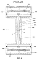
従来より、図6の概略平面断面図に示されるように、電磁石500により振動子510を図面の上下方向に振動させてダイヤフラム520を変位させ、搬送対象となっている流体を吸入および吐出(排出)させる電磁式ダイヤフラムポンプが知られている。
Conventionally, as shown in the schematic plan sectional view of FIG. 6, the
このような電磁式ダイヤフラムポンプにおいて、通常、振動子510の両端部には、対向する一対のダイヤフラム520が配置されており、振動子510の側面には一対の電磁石500が所定の間隔を空けた状態で振動子510の側面に沿って配置されている。そして、電磁石500の電磁石用のコイルには図示していない交流電源が接続されており、交流電源の周波数と同一回数の磁極の変化(極性変化)が生じるようになっており、交流電源に接続された電磁石500の極性変化に伴い振動子510は、交流電源と同じ周波数で往復運動するように構成されている。
In such an electromagnetic diaphragm pump, normally, a pair of
このような振動子510の往復運動に同期して振動子510の両端部に配置されたダイヤフラム520は、そのダイヤフラムの中央部を中心にして振動子510のストロークと同じ変位量で変形し、これにより、ダイヤフラム室530の容量の変化が生じ、逆止弁である吸入弁535および吐出弁536を介して流体の吸入および吐出の操作、すなわちポンプ操作が行なわれる。
The
このような電磁式ダイヤフラムポンプにおいて、輸送対象が可燃性ガスである場合には、例えば、電気が流れる部位を有する電磁石500等から当該可燃性ガスを完全にシャットアウトする必要がある。そのため、図6に示される従来ダイカスト部品において電磁石500と振動子510を隔離するために、振動子510を取り囲む仕切筒状部550を作り、万が一、ダイヤフラム520等の破損によって、可燃性ガスがポンプ内部に漏れ出た場合であっても、漏洩した可燃性ガスが振動子510を取り囲む仕切筒状部550の内部550aから交流電源が接続されている電磁石500側へと流入しないような構造が採択されている。
In such an electromagnetic diaphragm pump, when the object to be transported is combustible gas, for example, the combustible gas needs to be completely shut out from the
しかしながら、図6に示されるように、例えば、振動子510を取り囲む仕切筒状部550とポンプボディとを一体的にアルミダイカストで製造する場合、仕切筒状部550の中空内部を成形するために、一対のインナーコア部材(図示していない)を装着する必要がある。そして、当該一対のインナーコア部材(図示していない)には、成形後の抜きテーパ600を設けつつ、かつ、両側から対向配置される一対のインナーコア部材(図示していない)を、図面のラインGの箇所で突合せ構造にする必要がある。
However, as shown in FIG. 6, for example, when the partition
さらには、仕切筒状部550の外側に電磁石500を配置するためのスペースを形成するために当該部分に配置されるコア部材(図示していない)にも、仕切筒状部550の外部ラインHの図面の紙面奥域方向に沿った抜きテーパが必要となる。
Furthermore, an external line H of the partition
このように仕切筒状部550の内面に抜きテーパ600を設けること、および仕切筒状部550の外部ラインHの紙面奥域方向に沿って抜きテーパを設けることによって、仕切筒状部550は、対向配置される電磁石500の面と向き合う面の肉厚分布が一定でなく、厚さの厚い部分と薄い部分が存在するとともに、ラインHについては紙面奥域方向に傾斜が生じることとなる。これらの理由によって、電磁石500との間隙を狭くすることができないので、電磁石間ギャップが広がることによる性能低下、すなわち、電磁石500から振動子510に加わる力を大きくすることができないという不都合が生じる。また、抜きテーパ600による肉厚分布が一定でない箇所において、できるだけ、肉薄にて対応しようとした場合に、気泡等の発生に起因するいわゆる鋳物の巣が発生している場合には、仕切筒状部550の壁部に連通穴が部分的に生じることがあり、可燃性ガスが電磁石500側に流入してしまうおそれがある。
Thus, by providing the
また、仕切筒状部550の成形時に、内部に付き合わせ面(ラインGの箇所)にバリが発生した場合には、その後のバリ取り操作に多大の工数が必要となる。
Further, when burrs are generated on the abutting surface (location of the line G) when the partition
本願の課題とは異なるが、本願と類似する構成を有すると思われる先行技術として、特開2006−169988号公報がある。 Japanese Patent Application Laid-Open No. 2006-169988 is a prior art which is different from the subject of the present application but is considered to have a configuration similar to that of the present application.
引用された特開2006−169988号公報における発明は、電磁石の捲きコイル部に電流を流すことで発生した熱が、振動子を介してあるいは直接ダイアフラムに伝達してダイアフラムが熱され、ダイアフラムが高温に晒され熱劣化により長寿命化を図れないという問題を解決するために提案されたものでり、ケース(20)の内部に可動子(30)およびダイアフラム(40)を配置し、ケース(20)の外部に電磁石部(50)を配置する構成を採択している。このため、ケース(20)の可動子収納部(21)が隔壁となって、電磁石部(50)にて発生する熱エネルギーを遮断し、ダイアフラム(40)が熱されて劣化するのを防止でき、ダイアフラム(40)の長寿命化を図ることができるとされている。 In the cited Japanese Patent Application Laid-Open No. 2006-169988, the heat generated by passing an electric current through the coil portion of the electromagnet is transmitted to the diaphragm via the vibrator or directly, and the diaphragm is heated, so that the diaphragm is heated to a high temperature. It was proposed to solve the problem that it was not possible to extend the life due to thermal degradation due to thermal degradation, and the mover (30) and the diaphragm (40) were arranged inside the case (20), and the case (20 The configuration in which the electromagnet part (50) is arranged outside the) is adopted. For this reason, the mover storage part (21) of the case (20) serves as a partition, cuts off the heat energy generated in the electromagnet part (50), and can prevent the diaphragm (40) from being heated and deteriorated. It is said that the life of the diaphragm (40) can be extended.
このような可動子収納部(21)を備えるケース(20)は、非導電性プラスチックなど非導電性部材から構成されており、この場合でもやはり成形の都合上、上記の抜きテーパが必要となり、対向配置される電磁石の面と向き合う面の肉厚分布が一定でなく、必ず厚さの厚い部分と薄い部分が存在することとなり、上述したように電磁石間ギャップが広くなることによるポンプ性能の低下、仕切筒状部の内部に付き合わせ面からのバリ発生等の問題は解消されていない。なお、上記の括弧内の数字は特許文献1で用いられている図面に付された数字である。
The case (20) provided with such a mover storage part (21) is composed of a nonconductive member such as a nonconductive plastic. Even in this case, the above-described taper is necessary for the sake of molding, The thickness distribution of the surface facing the opposite electromagnet surface is not constant, there will always be a thick part and a thin part, and as mentioned above, the gap between the electromagnets becomes wide and the pump performance decreases. In addition, problems such as the occurrence of burrs from the abutting surface inside the partition cylindrical portion have not been solved. The numbers in the parentheses are the numbers attached to the drawings used in
このような実状のもとに本発明は創案されたものであって、その目的は、例えば、ダイヤフラムの破損等によって流体がポンプ内部に漏れ出た場合において、漏れ出た流体が電気が流れる通電部位に進入できないような隔離構成を備え、この隔離構成による隔離作用を確実に発現させて漏洩に起因する事故等の発生を未然に防ぐとともに、電磁式ポンプの性能低下を抑制することができる電磁式ダイヤフラムポンプを提供することにある。 The present invention has been devised under such circumstances, and its purpose is, for example, when the fluid leaks into the pump due to a diaphragm breakage, etc. An electromagnetic structure that has an isolation structure that cannot enter the site, and that can reliably prevent the occurrence of accidents and the like due to leakage by reliably expressing the isolation action by this isolation structure, and can suppress the deterioration of the performance of the electromagnetic pump It is in providing a type diaphragm pump.
このような課題を解決するために、本発明の電磁式ダイヤフラムポンプは、電磁石と、電磁石の極性変化に伴い振動する振動子と、振動子の端部に配置されるダイヤフラムと、ダイヤフラムの周縁部を挟持して固定することができるダイヤフラム台およびダイヤフラム保持部と、前記振動子を覆う振動子カバーを有し、一対の前記ダイヤフラム台と一対の前記ダイヤフラムとによって、ダイヤフラムより内側に一対の内隔室が形成され、当該一対の内隔室を連通させるように、前記ダイヤフラム台とは別体の振動子カバーが取り付けられ、前記ダイヤフラム台は、ダイヤフラムの周縁部を挟持する作用をする挟持基部と、振動子の端部分を通過させる開口部と、当該開口部の外周部に形成され、前記振動子カバーの端部を振動子カバーパッキンとともに収納する収納部と、を有し、前記振動子カバーは、一対の前記ダイヤフラム台を結ぶ長手方向に対して垂直断面で見た場合、電磁石と対向するように配置される一対の側面板部とこれらの側面板部を連結する連結板部を備える一連の構造体であり、側面板部は均一な肉厚を有して構成される。 In order to solve such problems, an electromagnetic diaphragm pump according to the present invention includes an electromagnet, a vibrator that vibrates with a change in polarity of the electromagnet, a diaphragm disposed at an end of the vibrator, and a peripheral portion of the diaphragm. A diaphragm base and a diaphragm holding portion that can be sandwiched and fixed, and a vibrator cover that covers the vibrator, and a pair of diaphragms inside the diaphragm by the pair of diaphragm base and the pair of diaphragms. A chamber cover is formed and a vibrator cover separate from the diaphragm base is attached so that the pair of inner compartments communicate with each other. An opening for passing the end portion of the vibrator, and an outer peripheral portion of the opening. Have a, a housing part for housing with the transducer cover, when viewed in vertical cross-section to the longitudinal direction connecting the pair of the diaphragm base, a pair of side plate portions which are arranged so as to face the electromagnet And a connecting plate portion for connecting the side plate portions, and the side plate portion is configured to have a uniform thickness .
また、本発明の電磁式ダイヤフラムポンプの好ましい態様として、前記振動子カバーの両端部は、それぞれ、対向する一対のダイヤフラム台に、接合箇所における気密性を保持するように固着され構成される。 Moreover, as a preferable aspect of the electromagnetic diaphragm pump of the present invention, both ends of the vibrator cover are fixedly configured to a pair of opposing diaphragm bases so as to maintain airtightness at the joint portion.
また、本発明の電磁式ダイヤフラムポンプの好ましい態様として、前記収納部は、前記開口部の外周部に形成された振動子カバーパッキンを載置するパッキン載置面と、当該パッキン載置面の外周部に突出され、振動子カバーの端部をガイドして嵌着する部材となるリブ体と、を有するように構成される。 Moreover, as a preferable aspect of the electromagnetic diaphragm pump of the present invention, the storage portion includes a packing mounting surface on which a vibrator cover packing formed on the outer peripheral portion of the opening is mounted, and an outer periphery of the packing mounting surface. And a rib body that is a member that guides and fits the end portion of the vibrator cover.
また、本発明の電磁式ダイヤフラムポンプの好ましい態様として、前記振動子カバーは、非磁性材料から構成される。 As a preferred embodiment of the electromagnetic diaphragm pump of the present invention, the vibrator cover is made of a nonmagnetic material.
また、本発明の電磁式ダイヤフラムポンプの好ましい態様として、前記非磁性材料はアルミニウムまたはアルミニウム合金から構成される。 As a preferred embodiment of the electromagnetic diaphragm pump of the present invention, the nonmagnetic material is made of aluminum or an aluminum alloy.
また、本発明の電磁式ダイヤフラムポンプの好ましい態様として、前記振動子カバーの端部をガイドして嵌着する部材となるリブ体は、閉ループの凸部の一部を切り欠いた切欠部を備え、前記振動子カバーパッキンは閉ループのシール部と、当該シール部から外方に突出する突起部を備え、該振動子カバーパッキンの突起部が、前記リブ体の切欠部内に嵌着されるように構成される。 As a preferred aspect of the electromagnetic diaphragm pump of the present invention, the rib body serving as a member that guides and fits the end portion of the vibrator cover includes a notch portion in which a part of the convex portion of the closed loop is notched. The vibrator cover packing includes a closed loop seal part and a protrusion part protruding outward from the seal part, and the protrusion part of the vibrator cover packing is fitted into the notch part of the rib body. Composed.
また、本発明の電磁式ダイヤフラムポンプの好ましい態様として、前記ダイヤフラムの外側に配置されたダイヤフラム保持部は、弁を備える弁ケース本体として機能を有し、吸入弁および吐出弁を有するように構成される。 Further, as a preferred aspect of the electromagnetic diaphragm pump of the present invention, the diaphragm holding portion disposed outside the diaphragm has a function as a valve case body including a valve, and is configured to have an intake valve and a discharge valve. The
また、本発明の電磁式ダイヤフラムポンプの好ましい態様として、吸入弁および吐出弁は、それぞれ、肉薄円形状の弁傘部と、この弁傘部の中央部から突出する弁固定軸とを備えてなるように構成される。 Moreover, as a preferable aspect of the electromagnetic diaphragm pump of the present invention, each of the suction valve and the discharge valve includes a thin circular valve umbrella portion and a valve fixing shaft that protrudes from the central portion of the valve umbrella portion. Configured as follows.
また、本発明の電磁式ダイヤフラムポンプの好ましい態様として、前記弁ケース本体は、弁取り付け孔部、および吸入または吐出のための連通孔が形成された隔壁を備え、前記弁固定軸が弁取り付け孔部に挿着され、前記肉薄円形状の弁傘部が連通孔の通気の開閉弁機能を果たしてなるように構成される。 Further, as a preferred aspect of the electromagnetic diaphragm pump of the present invention, the valve case body includes a valve mounting hole portion and a partition wall in which a communication hole for suction or discharge is formed, and the valve fixing shaft is a valve mounting hole. is inserted in section, the valve umbrella portion of the thin circular shape really becomes so constructed off valve function of the vent communicating hole.
本発明の電磁式ダイヤフラムポンプは、電磁石と、電磁石の極性変化に伴い振動する振動子と、振動子の端部に配置されたダイヤフラムと、ダイヤフラムの周縁部を挟持して固定することができるダイヤフラム台およびダイヤフラム保持部と、前記振動子を覆う振動子カバーを有し、一対の前記ダイヤフラム台と一対の前記ダイヤフラムとによってダイヤフラムより内側に一対の内隔室が形成され、当該一対の内隔室を連通させるように、前記ダイヤフラム台とは別体の振動子カバーが取り付けられるように構成されているので、例えば、ダイヤフラムの破損等によって流体がポンプ内部に漏れ出た場合において、漏れ出た流体が電気が流れる通電部位に進入できないような隔離構成が形成でき、この隔離構成による隔離作用を確実に発現させて漏洩に起因する事故等の発生を未然に防ぐことができる。さらに、別体の振動子カバーの厚さを均一にすることができるので、電磁式ポンプの性能低下を抑制することができる。 The electromagnetic diaphragm pump of the present invention includes an electromagnet, a vibrator that vibrates as the polarity of the electromagnet changes, a diaphragm disposed at an end of the vibrator, and a diaphragm that can be fixed by sandwiching the peripheral edge of the diaphragm A pair of diaphragm chambers are formed inside the diaphragm by the pair of diaphragm bases and the pair of diaphragms, and the pair of diaphragm chambers. Since the vibrator cover separate from the diaphragm base is attached so as to communicate with each other, for example, when the fluid leaks into the pump due to the breakage of the diaphragm or the like, the leaked fluid Isolation structure that prevents entry of electricity into the current-carrying part can be formed, and the isolation action by this isolation structure is reliably expressed. The occurrence of accidents due to leakage Te can be prevented. Furthermore, since the thickness of the separate vibrator cover can be made uniform, it is possible to suppress the performance degradation of the electromagnetic pump.
以下、図面を参照しながら、本発明を実施するための実施形態について詳細に説明する。
なお、本発明は以下に説明する形態に限定されることはなく、技術思想を逸脱しない範囲において種々変形を行なって実施することが可能である。また、添付の図面においては、説明のために上下、左右の縮尺を誇張して図示することがあり、実際のものとは縮尺が異なる場合がある。
Hereinafter, embodiments for carrying out the present invention will be described in detail with reference to the drawings.
In addition, this invention is not limited to the form demonstrated below, In the range which does not deviate from a technical thought, it can implement in various deformation | transformation. In the accompanying drawings, the vertical and horizontal scales may be exaggerated for the sake of explanation, and the actual scales may differ.
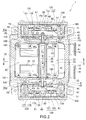
図1は、本発明の電磁式ダイヤフラムポンプを、個々の主要パーツに分解した状態を概略的に示す斜視図であり、図2は、本発明の電磁式ダイヤフラムポンプの主要部分の必要箇所を断面で示した平面図であり、図3は、本発明の電磁式ダイヤフラムポンプの主要部分の必要箇所を図2のII−II線矢視断面で示した正面図であり、本発明の電磁式ダイヤフラムポンプの主要部分の必要箇所を示した図面である。 FIG. 1 is a perspective view schematically showing a state in which the electromagnetic diaphragm pump of the present invention is disassembled into individual main parts, and FIG. 2 is a cross-sectional view of a necessary portion of the main part of the electromagnetic diaphragm pump of the present invention. FIG. 3 is a front view showing a necessary portion of the main part of the electromagnetic diaphragm pump of the present invention in a section taken along line II-II in FIG. 2, and the electromagnetic diaphragm of the present invention. It is drawing which showed the required location of the principal part of a pump.
また、図4(A)は、ダイヤフラム台と振動子カバーとの接合部位近傍を示した断面図であって図4(C)におけるA−A線矢視の平面図(断面図)であり、図4(B)は、ダイヤフラム台と振動子カバーとの接合部位近傍を示した断面図であって図4(C)におけるB−B線矢視の平面図(断面図)である。また、図4(C)は、図4(A)および図4(B)における切断位置を説明するための図面であり、図3に相当する断面図である。図5は、ダイヤフラム台と振動子カバーとが振動子カバーパッキンを介して組み立てられる状況を説明するための概略斜視図である。 FIG. 4A is a cross-sectional view showing the vicinity of the joint portion between the diaphragm base and the vibrator cover, and is a plan view (cross-sectional view) taken along line AA in FIG. FIG. 4B is a cross-sectional view showing the vicinity of the joint portion between the diaphragm base and the vibrator cover, and is a plan view (cross-sectional view) taken along line BB in FIG. 4C. 4C is a drawing for explaining the cutting positions in FIGS. 4A and 4B, and is a cross-sectional view corresponding to FIG. FIG. 5 is a schematic perspective view for explaining a situation where the diaphragm base and the vibrator cover are assembled via the vibrator cover packing.
図1に示されるように、本発明の電磁式ダイヤフラムポンプ1は、本体フレーム10内に配置された一対の電磁石20と、該一対の電磁石20の対向面の間に介在された振動子30と、この振動子30の両端部に配置された一対のダイヤフラム40と、ダイヤフラム40の(外周)周縁部を挟持して固定することができるダイヤフラム台50およびダイヤフラム保持部60とを有して構成されている。さらに、本発明においては、振動子30を一定の間隙を空けて覆う略筒状の振動子カバー100を有している。すなわち、一対の前記ダイヤフラム台50と一対の前記ダイヤフラム40とによって、当該ダイヤフラム40の位置よりも内側の位置に一対の内隔室165(図2参照)が対向するように形成され、当該一対の内隔室165を連通させるように、振動子カバー100が取り付けられている。
As shown in FIG. 1, the
このような振動子カバー100は、ダイヤフラム台50と一体的に成形されているのではなく、別部材として別体から構成されている。
Such a
図1に示されるように本体フレーム10は、図示される本実施の形態に限定されるものではないが、本実施形態では、電磁石20等を上部から挿入するための上部開口部13と、振動子30等が挿入できかつダイヤフラム台50およびダイヤフラム保持部60を内側に装着することのできる1対の側面開口部15とを有している。また、本体フレーム10の内部には、ポンプが運ぶ流動対象である流体を吸入するインプット連結口18に連通している連通路(図示していない)および流体を吐出するアウトプット連結口19に連通する連通路(図示していない)が、それぞれ別の形態で形成されている。
As shown in FIG. 1, the
本発明の構成を、さらに詳細に説明する。
本発明の電磁式ダイヤフラムポンプ1は、例えば、本体フレーム10の内側に配置された一対の電磁石20の極性変化に伴い、電磁石20の対向する方向に対して振動子30が略直角方向に往復運動できるように構成されている。振動子30は、例えば、その両端部に連結用シャフト31(図1、図2参照)が固定配置されており、前述のごとく振動子30の両端部には、対向する一対のダイヤフラム40が配置・固定されている。
The configuration of the present invention will be described in more detail.
In the
図1に示されるようにダイヤフラム40の内周部に位置する略中央部には、第1のセンタープレート71と、第2のセンタープレート75とがダイヤフラム40を挟持するように固定されており、これらの結合されたセンタープレート71,75に実質的に振動子30(連結用シャフト31,31)が固定される。
As shown in FIG. 1, a
前述したようにダイヤフラム40の周縁部は、ダイヤフラム台50およびダイヤフラム保持部60によって挟持され固定される。さらに、ダイヤフラム台50およびダイヤフラム保持部60は、本体フレーム10の側面開口部15内に装着され固定されるように構成されている。図2に示される実施形態においてその構成をより具体的にすると、ダイヤフラム40は、例えば、その周縁部において、内側に突出したリング状のビード部45を備え、ダイヤフラム台50は、ダイヤフラム40の内側に位置するように構成されており、ダイヤフラム保持部60は、ダイヤフラム40の外側に位置するように構成されている。
As described above, the peripheral edge of the
図1および図2に示されるように、ダイヤフラム40の外側に位置するダイヤフラム保持部60は、弁を備える弁ケース本体としての機能を有するとともに、ダイヤフラム40の周縁部を押し付けるようにしてケーシングパッキン80およびケーシングカバー85とともに本体フレーム10の側面に固着されるようになっている。
As shown in FIG. 1 and FIG. 2, the
このように弁ケース本体としての機能を有するダイヤフラム保持部60には、吸入弁120および吐出弁130がそれぞれ各所定の機能(吸入および吐出)を果たすように所定の向きに取りつけられている。これについては後に詳述する。
In this way, the
図2および図3を参照しつつ、本発明の電磁式ダイヤフラムポンプ1の基本的構造についてさらに詳細に説明する。
With reference to FIGS. 2 and 3, the basic structure of the
図2に示されるように、対向して配置される電磁石20の一方または双方は、例えば、E型の電磁石コア22と、このコア22に電磁石用のコイル23が巻かれた電磁石ボビン24を有して構成される。電磁石20の電磁石用のコイル23には交流電源に接続されるリード線25(図1参照)が接続されており、交流電源の周波数と同一回数の磁極の変化(極性変化)が生じるようになっている。
As shown in FIG. 2, one or both of the
前述したように一対の電磁石20の対向面の間隙には、電磁石20の極性変化に伴い往復運動する振動子30が電磁石20と接触しないように装入されている。振動子30は、本実施の形態の場合、図2に示されるようにプレート本体部35と、その両端に形成される連結用シャフト31を有し、プレート本体部35には、図示していないが、例えば四角状の極性の異なる永久磁石が取り付けられている。
As described above, the
<本発明における要部構造の説明>
本発明においては、前記したように振動子30を一定の間隙を空けて覆うように振動子カバー100が設けられている。振動子カバー100の長手方向に対する垂直断面の形状は、例えば図3に示されるような、長方形の角が丸まった変形長方形リング形状をなしているが、この形状に限定されることなく、振動子の断面形状や両サイドに配置される電磁石の形態等に応じて適宜選定することができる。本発明において、このような振動子カバー100は、ダイヤフラム台50とは別体の部材から構成されている。本発明において、別体とは、振動子カバー100とダイヤフラム台50とが同一の材質から構成されているか否かで判断されるものではなく、双方の部材が予め分離されていたものか否かで判断される。一体成形品は別体の構成ではない。
<Description of the essential structure in the present invention>
In the present invention, as described above, the
前述したように、一対のダイヤフラム台50と一対のダイヤフラム40とによってダイヤフラム40の位置より内側の位置に一対の内隔室165が形成され、当該一対の内隔室165を連通させるように、本発明における振動子カバー100が取り付けられている(図2参照)。振動子カバー100の両端部は、それぞれ対向する一対のダイヤフラム台50に、接合箇所での気密性を保持するように、例えば、振動子カバーパッキン155を介してダイヤフラム台50と固着されている。
As described above, the pair of
このように振動子カバー100と接合されるダイヤフラム台50は、ダイヤフラム40の周縁部を挟持する作用をする挟持基部51と、振動子30の端部分を通過させる開口部53と、この開口部53の外周部に形成され、振動子カバー100の端部を振動子カバーパッキン155とともに収納する収納部を有する。
As described above, the
このような収納部は、図2や図5に示されるように開口部53の外周部に形成された振動子カバーパッキンを載置するパッキン載置面53 aと、このパッキン載置面53aの外周部に突出され、振動子カバー100の端部を挿入させる際のガイド・嵌着の部材となるリブ体55aと、を有して構成される。リブ体55aは、閉ループの連続した凸部から構成してもよいが、本発明では好適な実施形態として、閉ループの凸部の一部を切り欠いた切欠部55bを備えるように構成されている。このようなリブ体55aの構造に対応するように振動子カバーパッキン155が形成される。すなわち、図5に示されるように、実質的にリブ体55aの内側に装着され、かつパッキン載置面53aの上に載置される振動子カバーパッキン155は、リブ体55aの内側に収納される閉ループのシール部155aと、該シール部155aの略中央部の位置において外方に突出するように形成された突起部155bとを備えている。そして、この突起部155bが、リブ体55aの切れ間となっている切欠部55b内に嵌着されるように構成されている。
As shown in FIGS. 2 and 5, such a storage unit includes a
本発明の実施形態は、このような特殊な切欠部55bや突起部155bの形態を有するがゆえに、図4(C)におけるA−A線とB−B線の2箇所の切り欠き位置における断面を図4(A)と図(B)の平面図として示している。図4(A)においては、リブ体55aが存在しない切欠部55bの箇所における断面図であるので、振動子カバーパッキン155を介して振動子カバー100の端部がダイヤフラム台50と当接する位置において、斜線で描かれた断面としてのリブ体55aは存在していない。また、図4(A)の位置における振動子カバーパッキン155は突起部155bが存在している箇所であるので、図示のごとく当該パッキンの断面幅は幅広となっている(図4(B)との比較において)。この一方で、図4(B)は、リブ体55aが存在している箇所(切欠部55bの存在しない位置)での断面図であるので、斜線で描かれた断面としてのリブ体55aが存在している。また、この位置における振動子カバーパッキン155は突起部155bが存在していないため、図示のごとく当該パッキンの断面幅は通常幅である幅狭となっている(図4(A)との比較において)。
Since the embodiment of the present invention has such
また、本発明における振動子カバー100は、特に電磁石と対向する側の面において、肉厚の均一性と平滑性が優れているように構成することが好ましい。すなわち、振動子カバー100は、図3や図5に示されるように、長手方向に対して垂直断面で見た場合、電磁石と対向するように配置される一対の側面板部101とこれらの側面板部101を連結する連結板部102を備える一連の構造体(略筒状体)であり、側面板部101は均一な肉厚を有して構成される。本発明でいう均一な肉厚とは、従来の意図した抜きテーパ(抜き勾配)の存在を認識することができない程度の均一なレベルをいう。
In addition, the
このような肉厚の精度を備えることによって、均一な薄肉の側面板部101を形成することができ、電磁式ポンプの性能低下を防止することが可能となる。
By providing such thickness accuracy, a uniform
上記のような均一な肉厚を有する筒状の振動子カバー100は、引抜加工により形成することができる。引抜加工とは、素材を加熱することなく室温で素材をダイスの狭い穴に通して引き抜くことによって加工する方法である。引抜く素材は一般に押出し材が多く使用されるが、必ずしも押出し材を初期のベースにする必要はない。
The
また、引抜加工に代えて押出加工で振動子カバー100を形成するようにしてもよい。押出加工は、アルミニウムやアルミニウム合金を例えば400〜500℃の熱間で押出す方法である。一般には円柱の金属塊(ビレット)を押出機を用いて、強い圧力を加えて各種の形状を持つダイス穴から押出され、細長い押出し材が形成される。
Further, the
なお、振動子カバー100は、アルミニウムやアルミニウム合金等の非磁性材料から構成される。さらに、電磁式ダイヤフラムポンプの構成についての説明を加える。
The
図2に示されるように、本体フレーム10の側面開口部15(図1参照)の中に固着されるダイヤフラム保持部60の凹部と、ケーシングパッキン80を介して形成されるケーシングカバー85とによって、区画された吸気室150が形成される。この吸気室150は、図示しない連通路を経由してインプット連結口18に連通している。略同様な手法で、図2に示されるように、本体フレーム10の側面開口部15(図1参照)に固着されるダイヤフラム保持部60と、ケーシングパッキン80を介して形成されるケーシングカバー85とによって、区画された吐出室170が形成される。この吐出室170は、図示しない連通路を経由してアウトプット連結口19に連通している。なお、吸気室150と吐出室170とは隔壁69によって区画されている。
As shown in FIG. 2, the concave portion of the
吸気室150を区画するダイヤフラム保持部60の仕切り壁61には、図示のごとく吸入弁120が内側から装着されている。吸入弁120は、シール弁として機能する肉薄円形状の弁傘部121と、この弁傘部121の中央部から突出する弁固定軸125を備えて構成される。弁固定軸125は仕切り壁61に形成された固定孔に装着・固定される(図2)。図示していないが、弁固定軸125の先端部には、通常、固定後の抜け防止のための突起状の係止部を形成しておくことが望ましい。なお、弁傘部121の弁固定軸125が位置する側の平面が、いわゆる(弁)シール平面を構成する。
A
このような吸入弁120の弁作用により、図2に示されるように仕切り壁61に形成された弁通気孔62を通して、インプット連結口18から流入される流体がダイヤフラム室160に吸入される。ダイヤフラム室160は、実質的にダイヤフラム40と、ダイヤフラム保持部60の内部の面(特に仕切り壁61)とによって区画されている。そして、ダイヤフラム室160に吸入された流体は、ダイヤフラム保持部60の仕切り壁61に外側から装着された吐出弁130の弁作用によって、仕切り壁61に形成された弁通気孔63を通して、吐出室170に入り、図示しない連通路を経由してアウトプット連結口19から吐出されるようになっている。
Due to the valve action of the
吐出弁130の形態そのものは、前述した吸入弁120と基本的に同じであり、その構成は図2に示されるごとく、シール弁として機能する肉薄円形状の弁傘部131と、この弁傘部131の中央部から突出する弁固定軸135を備えて構成される。弁固定軸135は仕切り壁61に形成された固定孔に装着・固定される(図2)。弁固定軸135の先端部には、通常、固定後の抜け防止のための突起状の係止部を形成しておくことが望ましい。なお、弁傘部131の弁固定軸135が位置する側の平面が、いわゆる(弁)シール平面を構成する。
The form of the
吸入弁120および吐出弁130の弁作用についてさらに説明する。交流電源に接続された電磁石20の極性変化に伴い振動子30は、交流電源と同じ周波数で図2に示される矢印(α)および矢印(β)方向に往復運動する。この振動子30の動きに同期して振動子30の両端部に配置されたダイヤフラム40は、そのダイヤフラム40の中央部を中心にして振動子30のストロークと同じ変位量で変形する。これにより、ダイヤフラム室160の容量の変化が生じ、図2の(β)方向側のダイヤフラム室160に注目すると、ダイヤフラム40が矢印(α)方向に変形した場合、ダイヤフラム室160は膨張して負圧になり、吸入弁120は開いて、流体がダイヤフラム室160内に吸入される。逆に、ダイヤフラム40が矢印(β)方向に変形した場合、(β)方向側のダイヤフラム室160は圧縮され正圧になり、吐出弁130は開いて、流体がダイヤフラム室160内から吐出室170に吐出される。これらの動作が交互に連続的に行われ、流体が連続的に吐出される。
The valve action of the
また、本発明においては、万が一、ダイヤフラム40等の破損によって、流体(例えば、可燃性ガス)がポンプ内部の内隔室165(図2参照)に流入してきても、一対の内隔室165は振動子カバー100によって気密性を保持したまま連通しているので、電源が接続されている電磁石側に流体が流入することはできない。
In the present invention, even if fluid (for example, combustible gas) flows into the internal compartment 165 (see FIG. 2) inside the pump due to damage to the
なお、本発明で用いられる吸入弁120および吐出弁130の具体的形態、例えば、弁傘部121(131)の外径の大きさや厚さ等は、電磁式ダイヤフラムポンプの仕様に応じて適宜設定するようにすればよい。また、用いる吸入弁120および吐出弁130の数についても同様である。吸入弁120および吐出弁130を構成するゴム材質に特に制限はない。例えば、EPDMやシリコーンゴムが好適な例として挙げられる。
The specific forms of the
また、ダイヤフラム40を構成するゴム材質に特に制限はないが、耐熱性や耐蝕性に優れ、可撓性にも優れる、フッ素ゴム、NBRが好適例として挙げられる。
Further, the rubber material constituting the
さらに、補足説明となるが、図1において、符号201はフレームパッキン、符号202はフレームカバー、符号211はタンクパッキン、符号212はタンクカバー、符号220は防振ゴム、符号230はブラケット、符号241,245はダイヤフラム保護シートを示す。
Further, in FIG. 1,
上述してきた本発明の電磁式ダイヤフラムポンプは、一対の前記ダイヤフラム台と一対のダイヤフラムとによって、ダイヤフラムより内側に一対の内隔室が形成され、一対の内隔室を連通させるように、前記ダイヤフラム台とは別体の振動子カバーが取り付けられるように構成されているので、例えば、ダイヤフラムの破損等によって流体がポンプ内部に漏れ出た場合において、漏れ出た流体が電気が流れる通電部位に進入できないような隔離構成が形成でき、この隔離構成による隔離作用を確実に発現させて漏洩に起因する事故等の発生を未然に防ぐことができる。さらに、別体の振動子カバーの厚さを均一にすることができるので、電磁式ポンプの性能低下を抑制することができる。 In the electromagnetic diaphragm pump of the present invention described above, a pair of inner chambers are formed inside the diaphragm by the pair of diaphragm bases and the pair of diaphragms so that the pair of inner chambers communicate with each other. Since the vibrator cover separate from the base is attached, for example, when fluid leaks into the pump due to diaphragm breakage, etc., the leaked fluid enters the current-carrying part where electricity flows. An isolation configuration that cannot be performed can be formed, and the isolation effect of this isolation configuration can be reliably expressed to prevent an accident or the like due to leakage. Furthermore, since the thickness of the separate vibrator cover can be made uniform, it is possible to suppress the performance degradation of the electromagnetic pump.
本発明は、家庭用燃料電池向け電磁式ダイヤフラムポンプ、流体としてLPG等の燃料ガスや空気を圧送用の電磁式ダイヤフラムポンプ等、流体輸送に関する装置技術の分野に利用することができる。 INDUSTRIAL APPLICABILITY The present invention can be used in the field of apparatus technology related to fluid transportation, such as an electromagnetic diaphragm pump for household fuel cells, an electromagnetic diaphragm pump for pumping fuel gas such as LPG as a fluid, and air.
1…電磁式ダイヤフラムポンプ
10…本体フレーム
15…側面開口部
20…電磁石
30…振動子
45…ビード部
40…ダイヤフラム
50…ダイヤフラム台
53…開口部
53a…パッキン載置面
55a…リブ体
55b…切欠部
60…ダイヤフラム保持部
100…振動子カバー
155…振動子カバーパッキン
DESCRIPTION OF
Claims (9)
一対の前記ダイヤフラム台と一対の前記ダイヤフラムとによって、ダイヤフラムより内側に一対の内隔室が形成され、当該一対の内隔室を連通させるように、前記ダイヤフラム台とは別体の振動子カバーが取り付けられ、
前記ダイヤフラム台は、ダイヤフラムの周縁部を挟持する作用をする挟持基部と、振動子の端部分を通過させる開口部と、当該開口部の外周部に形成され、前記振動子カバーの端部を振動子カバーパッキンとともに収納する収納部と、を有し、
前記振動子カバーは、一対の前記ダイヤフラム台を結ぶ長手方向に対して垂直断面で見た場合、電磁石と対向するように配置される一対の側面板部とこれらの側面板部を連結する連結板部を備える一連の構造体であり、側面板部は均一な肉厚を有して構成されることを特徴とする電磁式ダイヤフラムポンプ。 An electromagnet, a vibrator that vibrates with a change in polarity of the electromagnet, a diaphragm disposed at an end of the vibrator, a diaphragm base and a diaphragm holding section that can be fixed by sandwiching a peripheral edge of the diaphragm, and the vibration Having a vibrator cover covering the child,
The pair of diaphragm bases and the pair of diaphragms form a pair of inner compartments inside the diaphragm, and a vibrator cover separate from the diaphragm base is formed so that the pair of inner compartments communicate with each other. Attached,
The diaphragm base is formed on a sandwiching base that acts to sandwich the peripheral edge of the diaphragm, an opening that allows the end of the vibrator to pass through, and an outer periphery of the opening, and vibrates the end of the vibrator cover. possess a storage unit that housed with child cover packing, the,
The vibrator cover includes a pair of side plate portions disposed so as to face the electromagnet when viewed in a cross section perpendicular to the longitudinal direction connecting the pair of diaphragm bases, and a connecting plate that connects these side plate portions. parts is a series of structures comprising a side plate portion is configured to have a uniform thickness electromagnetic diaphragm pump according to claim Rukoto.
前記振動子カバーパッキンは閉ループのシール部と、当該シール部から外方に突出する突起部を備え、該振動子カバーパッキンの突起部が、前記リブ体の切欠部内に嵌着される請求項3ないし請求項5のいずれかに記載の電磁式ダイヤフラムポンプ。 The rib body, which is a member that guides and fits the end of the vibrator cover, includes a cutout portion in which a part of the convex portion of the closed loop is cut out,
4. The vibrator cover packing includes a closed loop seal portion and a protrusion protruding outward from the seal portion, and the protrusion of the vibrator cover packing is fitted into the notch of the rib body. The electromagnetic diaphragm pump according to claim 5 .
Priority Applications (3)
| Application Number | Priority Date | Filing Date | Title |
|---|---|---|---|
| JP2012239937A JP6050088B2 (en) | 2012-10-31 | 2012-10-31 | Electromagnetic diaphragm pump |
| KR1020130096481A KR101547520B1 (en) | 2012-10-31 | 2013-08-14 | Electromagnetic diaphragm pump |
| CN201310525719.2A CN103790810B (en) | 2012-10-31 | 2013-10-31 | Eletromagnetic diaphragm pump |
Applications Claiming Priority (1)
| Application Number | Priority Date | Filing Date | Title |
|---|---|---|---|
| JP2012239937A JP6050088B2 (en) | 2012-10-31 | 2012-10-31 | Electromagnetic diaphragm pump |
Publications (3)
| Publication Number | Publication Date |
|---|---|
| JP2014088841A JP2014088841A (en) | 2014-05-15 |
| JP2014088841A5 JP2014088841A5 (en) | 2015-09-24 |
| JP6050088B2 true JP6050088B2 (en) | 2016-12-21 |
Family
ID=50666784
Family Applications (1)
| Application Number | Title | Priority Date | Filing Date |
|---|---|---|---|
| JP2012239937A Active JP6050088B2 (en) | 2012-10-31 | 2012-10-31 | Electromagnetic diaphragm pump |
Country Status (3)
| Country | Link |
|---|---|
| JP (1) | JP6050088B2 (en) |
| KR (1) | KR101547520B1 (en) |
| CN (1) | CN103790810B (en) |
Families Citing this family (9)
| Publication number | Priority date | Publication date | Assignee | Title |
|---|---|---|---|---|
| CN104791226A (en) * | 2014-01-16 | 2015-07-22 | 蔡应麟 | Shock absorption structure of diaphragm booster pump |
| CN105089987B (en) * | 2014-05-20 | 2019-04-02 | 佛山市三角洲电器科技有限公司 | The vibration control structure and swing wheel structure of five booster cavity diaphragm pumps |
| GB2527658B (en) * | 2014-05-20 | 2017-06-14 | Lin Cai Ying | Four compression chamber diaphragm pump with vibration reducing and positioning structures |
| GB2527911B (en) * | 2014-05-20 | 2017-06-14 | Lin Cai Ying | Compressing diaphragm pump with vibration reducing and positioning structures |
| JP6080080B2 (en) * | 2014-05-20 | 2017-02-15 | 蔡応麟 | Vibration reduction structure of 4 compression chamber diaphragm pump |
| CN105090006B (en) * | 2014-05-20 | 2018-07-17 | 蔡应麟 | The vibration control structure of five booster cavity diaphragm pumps |
| CN105508206A (en) * | 2015-12-22 | 2016-04-20 | 佛山市威灵洗涤电机制造有限公司 | Booster pump |
| CN107061241A (en) * | 2017-06-14 | 2017-08-18 | 深圳市时光电子有限公司 | Safe mini membrane pump |
| JP7178838B2 (en) * | 2018-09-11 | 2022-11-28 | 大研医器株式会社 | Connection member, pump casing and injection device provided with said connection member |
Family Cites Families (10)
| Publication number | Priority date | Publication date | Assignee | Title |
|---|---|---|---|---|
| JPS5514965A (en) * | 1978-07-19 | 1980-02-01 | Hitachi Metals Ltd | Compound diaphragm pump |
| JPS63227977A (en) * | 1987-03-17 | 1988-09-22 | Takatsuki Denki Seisakusho:Kk | Cold air passing circuit for diaphragm pump |
| JP3370653B2 (en) * | 2000-01-06 | 2003-01-27 | 株式会社テクノ高槻 | Electromagnetic vibration pump and its manufacturing method |
| JP2002371968A (en) * | 2001-06-12 | 2002-12-26 | Techno Takatsuki Co Ltd | Electromagnetic vibrating pump and pump unit |
| JP4365558B2 (en) * | 2002-04-08 | 2009-11-18 | 株式会社テクノ高槻 | Electromagnetic vibration type diaphragm pump |
| JP4188207B2 (en) * | 2003-11-05 | 2008-11-26 | アルプス電気株式会社 | pump |
| JP4406556B2 (en) * | 2003-11-28 | 2010-01-27 | アルプス電気株式会社 | Electromagnetic pump |
| JP2006169988A (en) * | 2004-12-13 | 2006-06-29 | Nagano Keiki Co Ltd | Diaphragm pump |
| JP2006194181A (en) * | 2005-01-14 | 2006-07-27 | Nagano Keiki Co Ltd | Diaphragm pump |
| JP5216118B2 (en) * | 2011-04-08 | 2013-06-19 | 株式会社テクノ高槻 | Electromagnetic vibration type diaphragm pump with fluid leakage prevention function to electromagnetic part |
-
2012
- 2012-10-31 JP JP2012239937A patent/JP6050088B2/en active Active
-
2013
- 2013-08-14 KR KR1020130096481A patent/KR101547520B1/en active IP Right Grant
- 2013-10-31 CN CN201310525719.2A patent/CN103790810B/en active Active
Also Published As
| Publication number | Publication date |
|---|---|
| JP2014088841A (en) | 2014-05-15 |
| CN103790810A (en) | 2014-05-14 |
| CN103790810B (en) | 2016-12-07 |
| KR20140055960A (en) | 2014-05-09 |
| KR101547520B1 (en) | 2015-08-26 |
Similar Documents
| Publication | Publication Date | Title |
|---|---|---|
| JP6050088B2 (en) | Electromagnetic diaphragm pump | |
| US6533560B2 (en) | Electromagnetic oscillating type pump and method for manufacturing the same | |
| US9441623B2 (en) | Electromagnetic vibrating diaphragm pump | |
| JP2014088841A5 (en) | ||
| WO2003085264A9 (en) | Electromagnetic vibrating type diaphragm pump | |
| JP5550625B2 (en) | Electromagnetic diaphragm pump | |
| EP2645547A2 (en) | Linear motor cooling structure | |
| TW200821470A (en) | Diaphragm pump and thin channel structure | |
| US20140023531A1 (en) | Electromagnetic vibrating diaphragm pump with function preventing fluid leakage to electromagnetic portion | |
| GB2197914A (en) | Electromagnetic air pump | |
| JP6013791B2 (en) | Electromagnetic diaphragm pump | |
| JP2019035402A (en) | Miniature gas control device | |
| JP2014186924A (en) | Battery cooler and manufacturing method thereof | |
| CN210715006U (en) | Linear compressor | |
| JP6193656B2 (en) | Electromagnetic vibration type fluid pump | |
| US7621723B2 (en) | Electromagnetic pump | |
| JP4138989B2 (en) | Valve structure and electromagnetic diaphragm pump using the same | |
| JP2017026082A (en) | Solenoid valve, and atmospheric pressure control device equipped with the same | |
| JPH0413430Y2 (en) | ||
| JP3158011U (en) | Electromagnetic vibration pump and manufacturing method thereof | |
| JP2005220769A (en) | Electromagnetic pump | |
| JP5941105B2 (en) | Electrolyzer structure of diaphragm membrane electrolyzer | |
| CN210531115U (en) | Integrated pump valve and equipment thereof | |
| KR100556155B1 (en) | Structure for diaphragm into the air-pump | |
| CN213016730U (en) | Pump and method of operating the same |
Legal Events
| Date | Code | Title | Description |
|---|---|---|---|
| A521 | Request for written amendment filed |
Free format text: JAPANESE INTERMEDIATE CODE: A523 Effective date: 20150811 |
|
| A621 | Written request for application examination |
Free format text: JAPANESE INTERMEDIATE CODE: A621 Effective date: 20150811 |
|
| A977 | Report on retrieval |
Free format text: JAPANESE INTERMEDIATE CODE: A971007 Effective date: 20160420 |
|
| A131 | Notification of reasons for refusal |
Free format text: JAPANESE INTERMEDIATE CODE: A131 Effective date: 20160510 |
|
| A521 | Request for written amendment filed |
Free format text: JAPANESE INTERMEDIATE CODE: A523 Effective date: 20160704 |
|
| TRDD | Decision of grant or rejection written | ||
| A01 | Written decision to grant a patent or to grant a registration (utility model) |
Free format text: JAPANESE INTERMEDIATE CODE: A01 Effective date: 20161108 |
|
| A61 | First payment of annual fees (during grant procedure) |
Free format text: JAPANESE INTERMEDIATE CODE: A61 Effective date: 20161124 |
|
| R150 | Certificate of patent or registration of utility model |
Ref document number: 6050088 Country of ref document: JP Free format text: JAPANESE INTERMEDIATE CODE: R150 |
|
| S533 | Written request for registration of change of name |
Free format text: JAPANESE INTERMEDIATE CODE: R313533 |
|
| R350 | Written notification of registration of transfer |
Free format text: JAPANESE INTERMEDIATE CODE: R350 |
|
| R250 | Receipt of annual fees |
Free format text: JAPANESE INTERMEDIATE CODE: R250 |
|
| R250 | Receipt of annual fees |
Free format text: JAPANESE INTERMEDIATE CODE: R250 |
|
| R250 | Receipt of annual fees |
Free format text: JAPANESE INTERMEDIATE CODE: R250 |
|
| R250 | Receipt of annual fees |
Free format text: JAPANESE INTERMEDIATE CODE: R250 |