JP6050041B2 - Magnetic resonance imaging apparatus and FSE imaging method - Google Patents
Magnetic resonance imaging apparatus and FSE imaging method Download PDFInfo
- Publication number
- JP6050041B2 JP6050041B2 JP2012151957A JP2012151957A JP6050041B2 JP 6050041 B2 JP6050041 B2 JP 6050041B2 JP 2012151957 A JP2012151957 A JP 2012151957A JP 2012151957 A JP2012151957 A JP 2012151957A JP 6050041 B2 JP6050041 B2 JP 6050041B2
- Authority
- JP
- Japan
- Prior art keywords
- phase encoding
- echo
- echoes
- order
- fse
- Prior art date
- Legal status (The legal status is an assumption and is not a legal conclusion. Google has not performed a legal analysis and makes no representation as to the accuracy of the status listed.)
- Active
Links
- 238000002595 magnetic resonance imaging Methods 0.000 title claims description 33
- 238000003384 imaging method Methods 0.000 title claims description 25
- 238000002592 echocardiography Methods 0.000 claims description 86
- 238000005259 measurement Methods 0.000 claims description 52
- 238000012545 processing Methods 0.000 claims description 42
- 238000001208 nuclear magnetic resonance pulse sequence Methods 0.000 claims description 37
- 238000000034 method Methods 0.000 claims description 24
- 230000008859 change Effects 0.000 claims description 2
- 230000005284 excitation Effects 0.000 description 11
- 230000000694 effects Effects 0.000 description 7
- 238000010586 diagram Methods 0.000 description 6
- 230000006870 function Effects 0.000 description 6
- 230000003068 static effect Effects 0.000 description 6
- 238000005481 NMR spectroscopy Methods 0.000 description 4
- 230000005540 biological transmission Effects 0.000 description 4
- 230000004048 modification Effects 0.000 description 3
- 238000012986 modification Methods 0.000 description 3
- 238000012935 Averaging Methods 0.000 description 2
- 238000004364 calculation method Methods 0.000 description 2
- 238000013500 data storage Methods 0.000 description 2
- 230000003287 optical effect Effects 0.000 description 2
- 230000008569 process Effects 0.000 description 2
- 210000001519 tissue Anatomy 0.000 description 2
- 210000000577 adipose tissue Anatomy 0.000 description 1
- 238000012937 correction Methods 0.000 description 1
- 230000001419 dependent effect Effects 0.000 description 1
- 238000005516 engineering process Methods 0.000 description 1
- 238000010191 image analysis Methods 0.000 description 1
- 230000006872 improvement Effects 0.000 description 1
- 230000036278 prepulse Effects 0.000 description 1
- 230000009467 reduction Effects 0.000 description 1
- 230000004044 response Effects 0.000 description 1
- 238000005070 sampling Methods 0.000 description 1
- 238000009738 saturating Methods 0.000 description 1
- 238000012360 testing method Methods 0.000 description 1
- 230000001131 transforming effect Effects 0.000 description 1
Images


Description
この発明は、高速スピンエコー法に基づくパルスシーケンスを搭載した磁気共鳴イメージング装置(以下、MRI装置という)において、1回のRF励起後に連続して収集されるエコー毎に含まれる誤差磁場の影響を排除する技術に関する。 The present invention relates to a magnetic resonance imaging apparatus (hereinafter referred to as an MRI apparatus) equipped with a pulse sequence based on a high-speed spin echo method, and the influence of an error magnetic field included in each echo continuously collected after one RF excitation. It relates to technology to be eliminated.
MRI装置では、撮像対象や画像種に対応して種々のパルスシーケンスが用いられている。それらパルスシーケンスのうち高速スピンエコー法(FSE法)と呼ばれるパルスシーケンス(FSEシーケンス)は、その撮像時間の短さと撮像可能な画像種の多様さのため広く用いられている。 In the MRI apparatus, various pulse sequences are used corresponding to the imaging target and the image type. Among these pulse sequences, a pulse sequence (FSE sequence) called a fast spin echo method (FSE method) is widely used because of its short imaging time and variety of image types that can be imaged.
FSE法では、90°RFパルスによるスピンの励起後に、励起したスピンを複数の180°RFパルスを用いて繰り返し反転することで複数のスピンエコーを得る。1回の励起後に収集されるエコー群をエコートレイン(ETL)といい、マルチショットの励起回数をショット数(Shot)という。これらエコーを発生させるためのRFパルスと、エコーをエンコードする傾斜磁場パルスには高度で正確な制御が要求される。FSE法を実現するためのソフトウェアであるパルスシーケンスには、理想的なRFパルスと傾斜磁場パルスの強度及びタイミングが記述されている。しかし実際にハードウェアによって発生される傾斜磁場パルス及びRFパルスには誤差が生じるため、理想通りのパルスシーケンスを静磁場空間内で実現することは難しい。このため各エコーは磁場誤差を含むこととなり、それを用いた画像にはアーチファクトを生じる。 In the FSE method, after exciting a spin by a 90 ° RF pulse, a plurality of spin echoes are obtained by repeatedly inverting the excited spin using a plurality of 180 ° RF pulses. An echo group collected after one excitation is called an echo train (ETL), and the number of multi-shot excitations is called a shot number (Shot). The RF pulse for generating these echoes and the gradient magnetic field pulse for encoding the echoes require advanced and accurate control. The pulse sequence, which is software for realizing the FSE method, describes the ideal RF pulse and gradient magnetic field pulse intensity and timing. However, since an error occurs in the gradient magnetic field pulse and the RF pulse actually generated by hardware, it is difficult to realize an ideal pulse sequence in the static magnetic field space. For this reason, each echo includes a magnetic field error, and an artifact is generated in an image using the echo.
この問題については種々の改善策が提案されている。例えば非特許文献1や特許文献1には、プリスキャンによってリファレンスデータを取得し、その結果を用いてパルスシーケンスを調整することで、エコーデータ自体を可能なかぎり理想に近い状態で収集する方法が提案されている。
Various improvement measures have been proposed for this problem. For example, in
上述のようなパルスシーケンス自体を調整する技術では、エコートレインの全エコーに一定の誤差が生じていることを前提として一様な調整を行うため、例えば、エコートレイン内のエコー毎に異なる誤差が生じている場合には対応することができない。また精度良い調整を行うためには、プリスキャンを繰り返す必要があり撮像時間の延長を招くことになる。 In the technique for adjusting the pulse sequence itself as described above, since uniform adjustment is performed on the assumption that a certain error has occurred in all echoes of the echo train, for example, there are different errors for each echo in the echo train. If it happens, we cannot respond. In addition, in order to perform an accurate adjustment, it is necessary to repeat the pre-scan, which causes an increase in imaging time.
本発明は、エコートレイン内の各エコーの誤差を極力回避して、k空間データの不連続性により再構成画像に生じるアーチファクトを低減することを課題とする。 An object of the present invention is to avoid an error of each echo in an echo train as much as possible and reduce artifacts generated in a reconstructed image due to discontinuity of k-space data.
上記課題を解決するため本発明は、FSEシーケンスのエコートレイン内のエコーに、2つ毎に隣接するエコーを連続する位相エンコードとするように、位相エンコードの順序を設定し、FSEシーケンスのエコートレインの各エコーを、それぞれ設定された位相エンコードの順序で計測する。 In order to solve the above-mentioned problem, the present invention sets the order of phase encoding so that the echoes in the echo train of the FSE sequence are consecutive phase encodes every two adjacent echoes, and the echo train of the FSE sequence Are measured in the order of the phase encoding set.
本発明によれば、エコートレイン内の各エコーの誤差を極力回避して、k空間データの不連続性により再構成画像に生じるアーチファクトを低減することができる。 According to the present invention, an error of each echo in the echo train can be avoided as much as possible, and artifacts generated in a reconstructed image due to discontinuity of k-space data can be reduced.
以下、本発明の実施の形態を、図面を参照して説明する。まず本発明が適用されるMRI装置の概要とこのMRI装置で実行される高速スピンエコー法のパルスシーケンスを、図1及び図2を参照して説明する。 Hereinafter, embodiments of the present invention will be described with reference to the drawings. First, an outline of an MRI apparatus to which the present invention is applied and a pulse sequence of a fast spin echo method executed by the MRI apparatus will be described with reference to FIG. 1 and FIG.
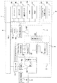
図1に示すMRI装置は、主な構成として、静磁場発生磁気回路2と、傾斜磁場発生部3と、送信部5と、受信部6と、信号処理部7と、シーケンサ4と、中央処理装置(CPU)8と、操作部(ユーザーインターフェイス部)9とを備えている。
The MRI apparatus shown in FIG. 1 mainly includes a static magnetic field generation
静磁場発生磁気回路2は、被検体1が置かれる空間に均一な静磁場を発生させるもので、図示していないが永久磁石方式又は常電導方式あるいは超電導方式の磁場発生手段が配置されている。静磁場の向きによって、被検体の体軸と平行な水平磁場方式、体軸と直交する垂直磁場方式がある。
The static magnetic field generating
傾斜磁場発生部3は、X、Y、Zの三軸方向に巻かれた傾斜磁場コイル31と、それぞれのコイルを駆動する傾斜磁場電源32とから成り、シーケンサ4から命令にしたがってそれぞれのコイルの傾斜磁場電源32を駆動することにより、任意の三軸方向の傾斜磁場Gs、Gp、Gfを被検体1に印加することができる。この傾斜磁場の加え方により、被検体1に対するスライス面を設定することができ、またエコー信号をエンコードし位置情報を付与する。
The gradient magnetic
送信部5は、シーケンサ4から送出される高周波磁場パルスにより被検体1の生体組織を構成する原子の原子核に核磁気共鳴を起こさせるために高周波信号を照射するもので、高周波発振器51と、変調器52と、高周波増幅器53と、送信側の高周波コイル54とを備え、高周波発振器51から出力された高周波パルスを高周波増幅器53で増幅した後に被検体1に近接して配置された送信側の高周波コイル54に供給することにより、電磁波(高周波信号)が被検体1に照射されるようになっている。
The
受信部6は、被検体1の生体組織の原子核の核磁気共鳴により放出されるエコー信号(NMR信号)を検出するもので、受信側の高周波コイル61と、増幅器62と、直交位相検波器63と、A/D変換器64とを備え、送信側の高周波コイル54から照射された電磁波による被検体1の応答の電磁波(NMR信号)を被検体1に近接して配置された受信側の高周波コイル61で検出し、増幅器62及び直交位相検波器63を介してA/D変換器64に入力してディジタル量に変換し、さらにシーケンサ4からの命令によるタイミングで直交位相検波器63によりサンプリングされた二系列の収集データとし、信号処理部7に送る。
The
信号処理部7は、受信部6で検出したエコー信号を用いて画像再構成演算を行うと共に画像表示をするもので、エコー信号についてフーリエ変換、補正係数計算、画像再構成等の処理及びシーケンサ4の制御を行うCPU(演算処理部)8と、メモリ部と、データ格納部と、ディスプレイ75とを備えている。メモリ部は、経時的な画像解析処理及び計測を行うプログラムやその実行において用いる不変のパラメータなどを記憶するROM(読み出し専用メモリ)71と、前計測で得た計測パラメータや受信部6で検出したエコー信号、及び関心領域設定に用いる画像を一時保管すると共にその関心領域を設定するためのパラメータなどを記憶するRAM(随時書き込み読み出しメモリ)72などから成る。データ格納部は、CPU8で再構成された画像データを記録するもので、例えば光ディスク73や磁気ディスク74などを備える。ディスプレイ75は、光ディスク73又は磁気ディスク74から読み出した画像データを映像化して断層像として表示する。
The
シーケンサ(計測制御部)4は、撮像に必要な高周波磁場パルスや傾斜磁場パルスを所定のパルスシーケンスに従って印加する制御手段であり、CPU8の制御で動作し、MR画像のデータ収集に必要な種々の命令を送信部5、傾斜磁場発生部3及び受信部6に送るようになっている。また、操作部9は、信号処理部7が行う処理の制御情報を入力するためのユーザーインターフェイス部であり、トラックボール91、キーボード92等の入力手段や表示手段を備えている。信号処理部7に備えられたディスプレイが操作部9の表示手段を兼ねることができる。
The sequencer (measurement control unit) 4 is a control means for applying a high-frequency magnetic field pulse and a gradient magnetic field pulse necessary for imaging according to a predetermined pulse sequence, operates under the control of the
(本発明に係るパルスシーケンス)
次に、このMRI装置が実行するパルスシーケンスについて説明する。パルスシーケンスには撮像法に応じて多種のパルスシーケンスがあり、プログラムとして磁気ディスク74に記憶されており、撮像に際し、磁気ディスク74に記憶されたパラメータやユーザーが設定したパラメータとともにシーケンサ4に読みだされて実行される。本実施形態では、そのようなパルスシーケンスの一つとしてFSE法のパルスシーケンスが実行される。
(Pulse sequence according to the present invention)
Next, a pulse sequence executed by the MRI apparatus will be described. There are various types of pulse sequences depending on the imaging method, and they are stored on the
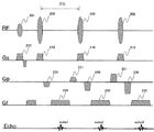
図2に、FSE法の基本的な2Dパルスシーケンスを示す。このパルスシーケンスでは、図示するように、検査対象内の所定の核スピン、通常プロトンを励起するRFパルス201を印加する。RFパルス201のフリップ角は例えば90°であり、以下では励起RFパルス或いは90°RFパルスという。この90°RFパルス201を印加した後、エコー時間TEに対しTE/2のタイミングで励起スピンを反転させるRFパルス202を印加する。このRFパルス202は反転パルス或いは180°RFパルスと呼ばれる。180°RFパルス印加後、時間TE/2が経過した時点でエコーecho1を収集する。以下、同一の時間間隔ITE(=TE)で180°RFパルスを印加し、180°RFパルス間でエコーecho2、echo3・・・を計測する。なお図2では、代表的に3つの180°RFパルスを示しているが、180°RFパルスの数はスピンの横緩和内で任意に設定することができ、1回の励起RFパルス後に全位相エンコードのエコーを計測(シングルショット)することもできるし、励起を繰り返し、全位相エンコードのエコーを複数回の励起で計測(マルチショット)することも可能である。
Fig. 2 shows the basic 2D pulse sequence of the FSE method. In this pulse sequence, as shown in the figure, an
また図2のパルスシーケンスでは、傾斜磁場として、RFパルス201、202の印加時にスライスを選択する傾斜磁場Gs210が印加され、エコー計測時に周波数エンコード方向の傾斜磁場Gf230が印加される。さらに各エコーを位相エンコードする傾斜磁場Gp220とリフェーズのための傾斜磁場Gp221が印加される。3D撮像の場合には、スライス方向にも位相エンコードする傾斜磁場とリフェーズする傾斜磁場が印加される。またk空間を放射状にスキャンするラジアルスキャンでは、位相エンコード方向の傾斜磁場と周波数エンコード方向の傾斜磁場とが組み合わせられて、エコーのエンコードと読出しとが行われる。
In the pulse sequence of FIG. 2, a gradient magnetic field Gs210 for selecting a slice is applied as the gradient magnetic field when the
その他、図2には示していないが、90°RFパルスの前に特定のスピン、例えば脂肪組織のスピンを飽和させるプリパルスや反転させるIRパルスなどを追加することも可能である。 In addition, although not shown in FIG. 2, it is also possible to add a specific spin, for example, a pre-pulse for saturating the spin of adipose tissue or an IR pulse for inversion before the 90 ° RF pulse.
このようなパルスシーケンスの実行によって計測されたエコー(サンプリングデータ)をメモリ空間に並べたものがk空間データとなる。説明を簡単にするために、図2に示す2Dパルスシーケンスで説明すると、k空間は横軸を周波数エンコード方向、縦軸を位相エンコード方向とする二次元平面であり、パルスシーケンスにおいてエコー毎に付与される位相エンコード量、即ち印加される位相エンコード傾斜磁場の強度がk空間における配置順序を決定する。図2に示すパルスシーケンスでは、配置順序はセントリックオーダーであり、RF励起後の1番目のエコーから順に位相エンコード量が所定の増量分ずつ増加する。これによりエコーはk空間の中心から順に高空間周波領域(以下、高域と略記する)に向かって配置される。本発明のMRI装置は、このk空間の配置順序、それ故エコートレインの各エコーに印加する傾斜磁場の印加ステップを調整することを特徴としている。 K-space data is obtained by arranging echoes (sampling data) measured by executing such a pulse sequence in a memory space. For the sake of simplicity, the 2D pulse sequence shown in FIG. 2 will be described. The k-space is a two-dimensional plane with the horizontal axis as the frequency encoding direction and the vertical axis as the phase encoding direction. The phase encoding amount to be applied, that is, the strength of the applied phase encoding gradient magnetic field determines the arrangement order in the k space. In the pulse sequence shown in FIG. 2, the arrangement order is a centric order, and the phase encoding amount is increased by a predetermined increment in order from the first echo after the RF excitation. As a result, the echoes are sequentially arranged from the center of the k space toward a high spatial frequency region (hereinafter abbreviated as a high region). The MRI apparatus of the present invention is characterized in that the arrangement order of the k space and hence the application step of the gradient magnetic field applied to each echo of the echo train is adjusted.
以上説明したMRI装置の構成とそれが実行するパルスシーケンスを踏まえて、本発明の各実施形態を説明する。 Each embodiment of the present invention will be described based on the configuration of the MRI apparatus described above and the pulse sequence executed by the apparatus.
<<第一実施形態>>
最初に本発明のMRI装置およびFSE撮像方法の第一の実施形態を説明する。本実施形態は、FSEシーケンスのエコートレイン内のエコーに、2つ毎に隣接するエコーを連続する位相エンコードとするように、位相エンコードの順序を設定する。以下、本実施形態を詳細に説明する。
<< First Embodiment >>
First, a first embodiment of the MRI apparatus and FSE imaging method of the present invention will be described. In the present embodiment, the order of phase encoding is set so that echoes adjacent to every two echoes in the echo train of the FSE sequence are phase encoded. Hereinafter, this embodiment will be described in detail.
(誤差磁場について)
まず本実施形態のMRI装置が対象とするエコーの磁場誤差について説明する。
(Error magnetic field)
First, the magnetic field error of the echo targeted by the MRI apparatus of this embodiment will be described.
図2に示したようなパルスシーケンスにおいて、180°RFパルスの反転毎に収集される各エコーは、90°RFパルス印加を起点とした計測タイミングや、180°RFパルスの反転回数が異なることからエコー毎に異なる誤差を含むことになる。この誤差には、計測前までのパルスシーケンスで蓄積された傾斜磁場パルス及びRFパルスの印加量誤差や、渦電流による不要磁場に起因する誤差などを含む。通常エコーは周波数エンコード傾斜磁場の中心で強度が最大となるように制御され、これらエコーを配置したk空間では、図3(a)の左図に示すように、k空間の周波数エンコード方向の中心にエコーピークが並ぶ。このようなk空間データを周波数エンコード方向にフーリエ変換して位相情報に変換すると、図3(a)の右図に示すように、位相はk空間全体に亘って均一な位相となる。 In the pulse sequence shown in Fig. 2, each echo collected for every 180 ° RF pulse inversion has different measurement timing starting from 90 ° RF pulse application and the number of 180 ° RF pulse inversions are different. Each echo will contain a different error. This error includes an application amount error of gradient magnetic field pulses and RF pulses accumulated in a pulse sequence before measurement, an error caused by an unnecessary magnetic field due to an eddy current, and the like. Normally, the echo is controlled so that the intensity is maximum at the center of the frequency encoding gradient magnetic field, and in the k space where these echoes are placed, the center in the frequency encoding direction of the k space is shown in the left figure of Fig. 3 (a). Echo peaks are lined up. Converting such k-space data into phase information by Fourier transform to the frequency encoding direction, as shown in the right diagram of FIG. 3 (a), the phase becomes a uniform phase throughout the k-space.
しかし、エコーに上述したような誤差があると、周波数エンコード傾斜磁場に対するエコーピークの位置が異なり、k空間データは、図3(b)に示すようにエコーピークが周波数エンコード方向の中心からずれたエコーを含むことになる。このようなk空間データを周波数エンコード方向にフーリエ変換すると、エコーによって位相の傾きが異なり、エコー間に不連続性を生じる。各エコーの位相誤差φは、一般式(1)で表わすことができる。
[数1]
φ=φ0+φ1r+φ2r2+・・・
式中、rは傾斜磁場中心からの距離、φ0は位置に依存しない位相誤差(0次誤差)、φ1rは位置に一次依存する位相誤差、φ2r2は位置に二次依存する位相誤差である。
However, if there is an error as described above in the echo, the position of the echo peak with respect to the frequency encoding gradient magnetic field is different, and the k-space data shows that the echo peak is shifted from the center in the frequency encoding direction as shown in Fig. 3 (b). Will contain an echo. When such k-space data is Fourier-transformed in the frequency encoding direction, the phase gradient differs depending on the echo, and discontinuity occurs between the echoes. The phase error φ of each echo can be expressed by the general formula (1).
[Equation 1]
φ = φ 0 + φ 1 r + φ 2 r 2 + ...
Wherein, r is the distance from the gradient center, .phi.0 does not depend on the position phase error (0-order errors), phi 1 r is the phase error of the primary dependent on the position, φ 2 r 2 is the phase of quadratic dependence on the position It is an error.
このうち0次の誤差即ちオフセット的に乗る誤差については、パルスシーケンスの調整により除去することが比較的容易であるが、2番目以降のエコーに生じ、蓄積していく誤差はパルスシーケンスの調整だけでは容易に解決できない。 Of these errors, the zero-order error, that is, the error that rides in an offset manner, is relatively easy to remove by adjusting the pulse sequence, but the error that occurs and accumulates in the second and subsequent echoes is only the adjustment of the pulse sequence. It cannot be solved easily.
本実施形態は、エコー毎に蓄積され、エコーによって異なる誤差や、撮像対象の撮像空間における位置に依存して生じる誤差を対象とし、k空間へのエコー配置順序を制御して誤差を低減することにより、実質的に誤差を除去した状態と同様の効果を得る。 The present embodiment is intended to reduce errors by accumulating each echo, and for errors that differ depending on the echo, or errors that occur depending on the position of the imaging target in the imaging space, and control the order of echo placement in k-space. Thus, the same effect as in the state where the error is substantially removed is obtained.
(本実施形態のエコー配置順序)
次に、本実施形態の、FSEシーケンスを用いてエコーを計測する際に、2つ毎に隣接するエコーを連続する位相エンコードで計測する方法を、図4、5を用いて具体的に説明する。
(Echo placement order of this embodiment)
Next, when measuring echoes using the FSE sequence of the present embodiment, a method of measuring adjacent echoes by every two consecutive phase encodings will be specifically described with reference to FIGS. .
FSEシーケンスは複数のエコーを連続して計測するが、その際に各位相エンコードのエコーの計測順序を任意に設定できる。代表的な計測順序としては、k空間の中心から高域側に向かう計測順序のセントリックオーダーと、k空間の一方の高域から中心を経由して他方の高域に向かう計測順序のシーケンシャルオーダーがある。 The FSE sequence measures a plurality of echoes continuously, and at that time, the measurement order of echoes of each phase encoding can be arbitrarily set. A typical measurement order is a centric order of the measurement order from the center of the k-space toward the high frequency side, and a sequential order of the measurement order from one high frequency of the k-space to the other high frequency via the center. There is.
図4(a)にETL=6でShot=8のセントリックオーダーの場合におけるk空間へのデータ充填の順番の従来例を示す。1,2,3,・・・の数字はエコートレインの何番目のエコーかを示している。本実施形態では、k空間の位相エンコード方向の正側領域と負側領域(つまり、ゼロ位相エンコードを挟む一方の領域と他方の領域)のデータを異なるショットでそれぞれ取得するセントリックオーダーとする。なお、図4(a)の例は、k空間を位相エンコード方向に6×2=12のセグメントに分割して、各セグメントの1つのエコーを1回のショットで計測し、ショット毎に各セグメントで計測するエコーを変えるセグメント計測を行う例でもある。
FIG. 4 (a) shows a conventional example of the order of data filling into the k space in the case of centric order with ETL = 6 and Shot = 8. The
セントリックオーダーにおいて、本実施形態の2つ毎に隣接するエコーを連続する位相エンコードで計測する場合には、1回のショット(励起)で計測するエコーの内で、隣接する2つのエコーをペアにして、これらのエコーの位相エンコードを連続にする。したがってk空間を位相エンコード方向に分割する分割数(セグメント数)は半分(つまりETLと同じ数)になる。図4(a)のETL=6でShot=8のセントリックオーダーにおいて、本実施形態の2つ毎に隣接するエコーを連続する位相エンコードで計測する場合を図4(b)に示す。この場合には、計測する6つのエコーのうちの、1番目と2番目のエコーをペアにして位相エンコードを連続(第1ショットでは位相エンコードは17,18となる)にし、3番目と4番目のエコーをペアにして位相エンコードを連続(第1ショットでは位相エンコードは10,9となる)にし、5番目と6番目のエコーをペアにして位相エンコードを連続(第1ショットでは位相エンコードは1,2となる)にする。また、セグメント数を12/2=6と半分にする。 In the centric order, when two adjacent echoes are measured by continuous phase encoding in this embodiment, two adjacent echoes are paired out of echoes measured by one shot (excitation). Thus, the phase encoding of these echoes is made continuous. Accordingly, the number of divisions (number of segments) for dividing the k space in the phase encoding direction is half (that is, the same number as ETL). In the centric order of ETL = 6 and Shot = 8 in FIG. 4 (a), FIG. 4 (b) shows a case where adjacent echoes are measured by continuous phase encoding every two in this embodiment. In this case, of the six echoes to be measured, the first and second echoes are paired to make phase encoding continuous (phase encoding is 17 and 18 in the first shot), and the third and fourth Paired echoes to make phase encoding continuous (phase encoding is 10 and 9 in the first shot), and paired fifth and sixth echoes to make phase encoding continuous (phase encoding is 1 in the first shot) , 2). The number of segments is halved to 12/2 = 6.
さらに、図12に、本実施形態の2つ毎に隣接するエコーを連続する位相エンコードで計測する場合の変形例を示す。図4(a)は、FSEシーケンスの奇数番目のショットと偶数番目のショットとの間で、2つ毎に隣接する(つまりペア内の)エコーのエンコード順序を入れ替える例であり、図4(b)は、図4(a)の例に加えてさらに、隣接するペア間で、ペア内の位相エンコード順序を入れ替える例を示す。換言すれば、図4(b)の例は、隣接するペア間で、ペア内の位相エンコードの増減方向を入れ替える例である。 Further, FIG. 12 shows a modification in the case where the echoes adjacent to every two in this embodiment are measured by continuous phase encoding. FIG. 4 (a) is an example in which the encoding order of echoes adjacent to each other (that is, in pairs) is switched between odd-numbered shots and even-numbered shots in the FSE sequence. ) Shows an example in which the phase encoding order in the pair is switched between adjacent pairs in addition to the example of FIG. 4 (a). In other words, the example of FIG. 4B is an example in which the increase / decrease direction of the phase encoding in the pair is switched between adjacent pairs.
シーケンシャルオーダーにおいても、セントリックオーダーと同様に、2つ毎に隣接するエコーに連続する位相エンコードを付与することができる。このように、一つのエコートレイン内で、k空間上で2つ毎に隣接するエコー対を複数取得する。 Also in the sequential order, as in the centric order, continuous phase encoding can be given to every two adjacent echoes. In this way, a plurality of adjacent echo pairs are acquired every two in the k space within one echo train.
なお、ETLが奇数の場合には、最後の1つのエコーを除く他の偶数個のエコーに対して、2つ毎に隣接するエコーに連続する位相エンコードを付与する。 When the ETL is an odd number, every second echo other than the last one echo is given a phase encoding that is continuous to adjacent echoes.
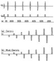
(本実施形態のFSEシーケンス形状)
図4のセントリックオーダーを実現するFSEシーケンスのパルスシーケンス形状を図5に示す。図5(a)(Centric)は、図4(a)の従来例に対応する、位相エンコード傾斜磁場(Gp)の印加パターンであり、図5(b)(Mod. Centric)は、図4(b)の本実施形態の2つ毎に隣接するエコーを連続する位相エンコードで計測する場合に対応する、位相エンコード傾斜磁場(Gp)の印加パターンである。図5に示すように、従来例(図5(a))と比較して、本実施形態(図5(b))では、位相エンコード傾斜磁場として2つ毎に非常に近い強度のパルスが連続することが理解される。この効果によって、本実施形態の2つ毎に隣接するエコーを連続する位相エンコードで計測する場合(図5(b))には、誤差磁場を相殺できることになる。なお、RFパルス(RF)、スライス傾斜磁場(Gs)、及び周波数エンコード傾斜磁場(Gr)は、従来例(図5(a))と本実施形態の例(図5(b))とで共通である。
(FSE sequence shape of this embodiment)
FIG. 5 shows the pulse sequence shape of the FSE sequence that realizes the centric order shown in FIG. Fig. 5 (a) (Centric) is an application pattern of the phase encoding gradient magnetic field (Gp) corresponding to the conventional example of Fig. 4 (a), and Fig. 5 (b) (Mod. Centric) is shown in Fig. 4 ( This is an application pattern of a phase encoding gradient magnetic field (Gp) corresponding to a case where echoes adjacent to every two of the present embodiment in b) are measured by continuous phase encoding. As shown in FIG. 5, compared to the conventional example (FIG. 5A), in this embodiment (FIG. To be understood. Due to this effect, the error magnetic field can be canceled when the echoes adjacent to every two in this embodiment are measured by continuous phase encoding (FIG. 5 (b)). Note that the RF pulse (RF), slice gradient magnetic field (Gs), and frequency encoding gradient magnetic field (Gr) are common to the conventional example (FIG. 5 (a)) and the example of this embodiment (FIG. 5 (b)). It is.
(各機能の説明)
本実施形態のFSE撮像方法を実現するためのCPU8の各機能を、図6の機能ブロック図を用いて説明する。本第一実施形態のCPU8は、FSEシーケンス設定部601と、位相エンコード順序設定部602と、FSEシーケンス生成部603と、画像再構成部604と、を有してなる。
(Description of each function)
Each function of the
FSEシーケンス設定部601は、計測順序(シーケンシャルオーダーかセントリックオーダーか)を含む撮像条件に基づいて、FSEシーケンスのETLとショット(Shot)数を算出する。そして、k空間を位相エンコード方向に分割するセグメント数をETLと同じ数とするセグメント計測を設定する。
The FSE
位相エンコード順序設定部602は、FSEシーケンス設定部601で設定された計測順序と算出されたETLとに基づいて、1回のショット(励起)で計測されるエコー(つまりエコートトレイン内のエコー)に、2つ毎に隣接するエコーを連続する位相エンコードとするように、位相エンコードの順序を設定する。具体的には、1番目のエコーから順に2つずつを対にして、各対のエコーに連続する位相エンコードを設定する。
The phase encoding
FSEシーケンス生成部603は、設定された計測順序と、算出されたETL及びショット数と、設定されたエコートレイン内の各エコーの位相エンコードと、に基づいて、FSEシーケンスの制御データを生成し、生成した制御データをシーケンサ4に通知する。
The FSE
画像再構成部604は、シーケンサ4から通知された各位相エンコードのエコーデータを、k空間の対応する位相エンコードの位置に充填し、充填が完了した(つまり、エコーの計測が終了した)k空間データをフーリエ変換して画像化し、その画像をディスプレイ75に表示する。
The
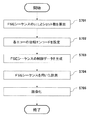
(処理フローの説明)
次に、上記各機能部が連携して行なう本実施形態の処理フローを図7に示すフローチャートに基づいて説明する。本処理フローは、予めプログラムとして磁気ディスク73に記憶されており、CPU8が磁気ディスク73からそのプログラムを読み込んで実行することにより実施される。本実施形態では、k空間への配置順序がセントリックオーダーである場合を基本とし、各エコーの位相特性を考慮した配置順序の制御を行う。以下、各処理ステップの処理内容を詳細に説明する。
(Description of processing flow)
Next, the processing flow of the present embodiment performed in cooperation with the above functional units will be described based on the flowchart shown in FIG. This processing flow is stored in advance on the
ステップS701で、操作者により、操作部9を介して、撮像方法としてFSE法のパルスシーケンスが選択され、その計測順序(シーケンシャルオーダーかセントリックオーダーか)を含む撮像条件が入力されると、FSEシーケンス設定部601は、FSEシーケンスのETLとショット(Shot)数を算出し、ETLと同じ数のセグメント数のセグメント計測を設定する。
In step S701, when the operator selects an FSE method pulse sequence as an imaging method via the
ステップS702で、位相エンコード順序設定部602は、ステップS701で設定された計測順序と算出されたETLとに基づいて、エコートレイン内のエコーに、2つ毎に隣接するエコーを連続する位相エンコードとするように各エコーの位相エンコード順を設定する。
In step S702, the phase encoding
ステップS703で、FSEシーケンス生成部603は、ステップS701で設定された計測順序と算出されたETL及びショット数と、ステップS702で設定されたエコートレイン内の各エコーの位相エンコードと、に基づいて、FSEシーケンスの制御データを生成し、生成した制御データをシーケンサ4に通知する。
In step S703, the FSE
ステップS704で、シーケンサ4は、ステップS703で生成されたFSEシーケンスの制御データに基づいて、FSEシーケンスを用いて、エコートレインの各エコーをそれぞれ設定された位相エンコードで計測を行い、計測したエコーを画像再構成部604に通知する。
In step S704, the
ステップS705で、画像再構成部604は、ステップS704で計測された各位相エンコードのエコーデータを、k空間に充填し、k空間データをフーリエ変換して画像化し、その画像をディスプレイ75に表示する。
以上までが本実施形態の処理フローの説明である。
In step S705, the
The above is the description of the processing flow of the present embodiment.
本実施形態の効果を示す一例として、上記ステップS705で得られるk空間データを周波数エンコード方向にフーリエ変換して得た位相像を図8に示す。図8(a)は従来例(Centric)の場合を示し、図8(b)は本実施形態(Mod Centric)の場合を示す。それぞれ、矢印で挟まれる位置での位相エンコード方向の直線に沿うプロファイルを示してある。図8(a)の従来例では、セグメント領域毎に位相に大きな段差が生じているが、図8(b)の本実施形態(Mod Centric)の場合では、このようなセグメント間での大きな位相段差が生じていないことが示されている。つまり、本実施形態の位相像には、誤差磁場の影響が相殺できていることが理解される。 As an example showing the effect of the present embodiment, FIG. 8 shows a phase image obtained by Fourier transforming the k-space data obtained in step S705 in the frequency encoding direction. FIG. 8A shows the case of the conventional example (Centric), and FIG. 8B shows the case of the present embodiment (Mod Centric). Each of the profiles along the straight line in the phase encoding direction at the position between the arrows is shown. In the conventional example of FIG. 8 (a), there is a large step in the phase for each segment area, but in the case of this embodiment (Mod Centric) of FIG. 8 (b), such a large phase between the segments. It is shown that there is no step. That is, it is understood that the influence of the error magnetic field can be offset in the phase image of the present embodiment.
以上説明したように、本実施形態は、FSEシーケンスを用いてエコートレイン内のエコーを計測する際に、2つ毎に隣接するエコーを連続する位相エンコードで計測する。その結果、位相エンコード傾斜磁場として非常に近い強度のパルスが連続することになり、誤差磁場を相殺できることになる。従って、エコートレイン内の各エコーの誤差を極力回避して、k空間データの不連続性により再構成画像に生じるアーチファクトを低減することができる。 As described above, according to the present embodiment, when echoes in the echo train are measured using the FSE sequence, every two adjacent echoes are measured by continuous phase encoding. As a result, pulses having very close intensities as the phase encoding gradient magnetic field continue, and the error magnetic field can be canceled out. Therefore, an error of each echo in the echo train can be avoided as much as possible, and artifacts generated in the reconstructed image due to discontinuity of k-space data can be reduced.
<<第二実施形態の>>
次に本発明のMRI装置およびFSE撮像方法の第二の実施形態を説明する。本実施形態は、前述の第一の実施形態で説明した、2つ毎に隣接するエコーを連続する位相エンコードで計測して得たデータと、連続する位相エンコードの順序を逆にして得たデータとを、複素加算することで、前述の第一の実施形態よりもさらに誤差磁場の影響を低減する。以下、本実施形態を詳細に説明する。
<< in the second embodiment >>
Next, a second embodiment of the MRI apparatus and FSE imaging method of the present invention will be described. In this embodiment, the data obtained by measuring every two adjacent echoes by continuous phase encoding described in the first embodiment, and the data obtained by reversing the order of successive phase encodings. By performing complex addition, the influence of the error magnetic field is further reduced as compared with the first embodiment described above. Hereinafter, this embodiment will be described in detail.
(本実施形態のエコー配置順序)
図8の位相像に示したように、前述の第一の実施形態で説明した2つ毎に隣接するエコーを連続する位相エンコードで計測するだけでは、偶数エコーの位相と奇数エコーの位相との間に細かい段差が生じてしまう場合がある。これは、偶数エコーと奇数エコーとの間で僅かに誤差磁場の影響が異なることによる。
(Echo placement order of this embodiment)
As shown in the phase image of FIG. 8, only by measuring every two adjacent echoes described in the first embodiment by continuous phase encoding, the phase of the even echo and the phase of the odd echo are calculated. There may be a small step between them. This is because the influence of the error magnetic field is slightly different between the even echo and the odd echo.
このような、偶数エコーと奇数エコーとの間の僅かに異なる誤差磁場の影響に基づく位相段差を除去するために、本実施形態では、2つ毎に隣接するエコーを連続する正順位相エンコードで計測されたデータと、2つ毎に連続する位相エンコードの順序を逆にした逆順位相エンコードで計測されたデータとを、複素加算することで、偶数エコーと奇数エコーとの間の位相段差を除去する。 In this embodiment, in order to eliminate such a phase step based on the influence of a slightly different error magnetic field between the even echo and the odd echo, in this embodiment, every two adjacent echoes are consecutively encoded in order of phase. The phase difference between the even echo and the odd echo is removed by complex addition of the measured data and the data measured by the reverse phase encoding in which the order of the successive phase encoding is reversed every two. To do.
なおデータの複素加算は、k空間データ同士の複素加算でもよいし、それぞれのk空間データを画像化した後に、画像データ同士の複素加算でもよい。例えば、図9のETL=6でShot=8のセントリックオーダーの場合に示すように、[エコー番号(位相エンコード)]とすると、図9(a)に示すように、正順位相エンコードのエコートレインを、
正順エコートレイン:[1(18)-2(17)]−[3(10)-4(9)]−[5(2)-6(1)]
とし、図9(b)に示すように、逆順位相エンコードのエコートレインを、
逆順エコートレイン:[1(17)-2(18)]−[3(9)-4(10)]−[5(1)-6(2)]
とすることができる。
The complex addition of data may be a complex addition of k-space data, or may be a complex addition of image data after imaging each k-space data. For example, as shown in the case of ETL = 6 and Shot = 8 centric order in FIG. 9, if [echo number (phase encoding)] is used, as shown in FIG. Train
Normal order echo train: [1 (18) -2 (17)]-[3 (10) -4 (9)]-[5 (2) -6 (1)]
As shown in Fig. 9 (b), the echo train of reverse phase encoding is
Reverse order echo train: [1 (17) -2 (18)]-[3 (9) -4 (10)]-[5 (1) -6 (2)]
It can be.
つまり、同じ位相エンコードのエコーデータが、偶数番目に計測されものと奇数番目に計測されたものになり、それぞれ位相段差の生じ方が逆になるので、両データをk空間で複素加算すると、加算データにおいては位相段差が除去されることになる。一方、画像空間でデータの複素加算を行う場合には、正順エコートレインの画像に生じるアーチファクトの位相と、逆順エコートレインの画像に生じるアーチファクトの位相と、が逆になるので、複素加算後の画像データにおいてはアーチファクトが除去されることになる。 In other words, echo data of the same phase encoding is the one measured evenly and the one measured oddly, and the way in which the phase difference is generated is reversed. The phase step is removed from the data. On the other hand, when performing complex addition of data in the image space, the phase of the artifact generated in the forward-order echo train image is opposite to the phase of the artifact generated in the reverse-order echo train image. Artifacts are removed from the image data.
なお、本実施形態でも、前述第一の実施形態で説明した図12に示した、2つ毎に隣接するエコーを連続する位相エンコードで計測する2つの変形例のいずれも適用可能である。つまり、図12(a)(b)に示した位相エンコード順序の例を正順位相エンコードとすると、ぞれぞれの位相エンコード順序を逆にしたものを逆順位相エンコードとすればよい。 Also in this embodiment, any of the two modifications shown in FIG. 12 described in the first embodiment and measuring two adjacent echoes by continuous phase encoding can be applied. In other words, if the example of the phase encoding order shown in FIGS. 12 (a) and 12 (b) is the normal phase encoding, the reverse phase encoding may be obtained by reversing the phase encoding order.
(本実施形態のFSEシーケンス形状)
本実施形態のFSEシーケンスは、基本的には図5(b)(Mod.Centric)に示したパルスシーケンス形状と同じなので詳細な説明は省略するが、位相エンコード傾斜磁場の印加パターンは、図5(b)(Mod.Centric)に示した印加パターンを正順エコートレイン用としたものと、この印加パターンを逆にして、2つ毎に隣接する2つの位相エンコード傾斜磁場の間で印加パターンを逆に(交換)して逆順エコートレイン用としたものになる。
(FSE sequence shape of this embodiment)
The FSE sequence of the present embodiment is basically the same as the pulse sequence shape shown in FIG. 5 (b) (Mod. Centric), and detailed description thereof is omitted, but the application pattern of the phase encoding gradient magnetic field is shown in FIG. (b) The applied pattern shown in (Mod.Centric) is for the forward echo train, and this applied pattern is reversed, and the applied pattern is changed between two adjacent phase encoding gradient magnetic fields. On the contrary (replacement), it becomes the thing for reverse order echo train.
(各機能の説明)
本実施形態のFSE撮像方法を実現するためのCPU8の各機能を説明する。本第二の実施形態のCPU8は前述の第一の実施形態と同じ各機能部を有するが、各機能の処理内容が異なる。以下、前述の第一の実施形態と異なる箇所のみを説明し、同一箇所の説明は省略する。
(Description of each function)
Each function of the
FSEシーケンス設定部601は、前述の第一の実施形態で説明した処理と同じなので説明を省略する。
Since the FSE
位相エンコード順序設定部602は、FSEシーケンス設定部601で設定された計測順序(シーケンシャルオーダーかセントリックオーダーか)と算出されたETLとに基づいて、1ショットで計測されるエコー(つまりエコートレイン内のエコー)に、2つ毎に隣接するエコーを連続する位相エンコードとするように、1番目のエコーから2つずつを対にする。そして、各対のエコーに連続する正順位相エンコードを付与する計測と、各対のエコーに連続する逆順位相エンコードを付与する計測と、を行うように、各エコーの位相エンコードの順序を設定する。
Based on the measurement order (sequential order or centric order) set by the FSE
FSEシーケンス生成部603は、設定された計測順序と算出されたETL及びショット数と、設定されたエコートレイン内の各エコーの位相エンコードと、に基づいて、正順位相エンコードの計測と逆順位相エンコードの計測とについてのFSEシーケンスの制御データをそれぞれ生成し、生成した制御データをシーケンサ4に通知する。
The FSE
画像再構成部604は、正順位相エンコードで計測されたデータと、逆順位相エンコードで計測されたデータとを、複素加算する。具体的には、計測された各回の各位相エンコードのエコーデータを、各回に対応するk空間の対応する位相エンコードの位置に充填し、充填が完了した(つまり、エコーの計測が終了した)ら、k空間データの複素加算を行う場合は、各回のk空間データを加算平均する。そして、加算平均後のk空間データをフーリエ変換して画像化し、その画像をディスプレイ75に表示する。画像空間で複素加算する場合には、各回のk空間データをそれぞれフーリエ変換して画像化し、各回の画像データの加算平均を求め、加算平均後の画像をディスプレイ75に表示する。
The
(処理フローの説明)
次に、上述の各機能が連携して行う本第二の実施形態の処理フローを説明する。本第二の実施形態の処理フローは、前述の第一の実施形態の処理フローと同様であるが、各ステップの処理内容が異なる。以下、前述の第一の実施形態と異なる処理内容のみ説明し、同一の処理内容については説明を省略する。ただし、第二の実施形態の処理ステップであることを明確にするために、ステップ番号に「CASE2」をつけて表す。
(Description of processing flow)
Next, the processing flow of the second embodiment performed in cooperation with the above-described functions will be described. The processing flow of the second embodiment is the same as the processing flow of the first embodiment described above, but the processing content of each step is different. Hereinafter, only processing contents different from those of the first embodiment will be described, and description of the same processing contents will be omitted. However, in order to clarify that it is a processing step of the second embodiment, the step number is represented by adding “ CASE2 ”.
ステップS701CASE2で、前述のステップS701の処理と同じなので説明を省略する。 Step S701 CASE2 is the same as the processing in step S701 described above, and a description thereof will be omitted.
ステップS702CASE2で、前述のステップS702の処理を正順位相エンコードでの計測として設定とし、さらに加えて、逆順位相エンコードでの計測として各対のエコーを連続する逆順位相エンコードで行うよう、各エコーの位相エンコードを設定する。 In step S702 CASE2 , each echo is set so that the processing in step S702 described above is set as measurement in forward phase encoding, and in addition, each pair of echoes is performed in continuous reverse phase encoding as measurement in reverse phase encoding. Set the phase encoding for.
ステップS703CASE2で、FSEシーケンス生成部603は、ステップS701CASE2で設定された計測順序と算出されたETL及びショット数と、ステップS702CASE2で設定された、正順位相エンコードでの計測と逆順位相エンコードでの計測におけるエコートレイン内の各エコーの位相エンコードと、に基づいて、各FSEシーケンスの制御データを生成し、生成した制御データをシーケンサ4に通知する。
In step S703 CASE2 , the FSE
ステップS704CASE2で、シーケンサ4は、ステップS703CASE2で生成されたFSEシーケンスの制御データに基づいて、正順位相エンコードのFSEシーケンスと逆順位相エンコードとを用いた計測をそれぞれ行い、計測したエコーを画像再構成部604に通知する。
In Step S704 CASE2 , the
ステップS705CASE2で、画像再構成部604は、ステップS703CASE2で正順位相エンコードと逆順位相エンコードで計測された各位相エンコードのエコーデータを、それぞれ正順位相エンコード用のk空間と逆順位相エンコード用のk空間に充填する。そして、k空間で複素加算する場合には、各k空間データを加算平均し、加算平均後のk空間データをフーリエ変換して画像化し、その画像をディスプレイ75に表示する。或いは、画像空間で複素加算する場合は、各k空間データをそれぞれフーリエ変換して画像化し、各画像データの加算平均を求め、加算平均画像をディスプレイ75に表示する。
以上までが本実施形態の処理フローの説明である。
In step S705 CASE2 , the
The above is the description of the processing flow of the present embodiment.
本実施形態の効果を示す一例として、上記ステップS405CASE2で得られる正順位相エンコード用のk空間データ[Positive(Pos)]と逆順位相エンコード用のk空間データ[Negative(Neg)]を周波数エンコード方向にフーリエ変換して得た位相像を図10に示す。図10(a)は正順位相エンコードの場合の位相像であり、図10(b)は逆順位相エンコードの場合の位相像である。それぞれ、矢印で挟まれる位置での位相エンコード方向の直線に沿うプロファイルを図10(c)に示してある。正順位相エンコードの場合の位相像と逆順位相エンコードの場合の位相像とでは、位相エンコード方向の僅かな位相段差の変化の仕方が全く逆であることが理解される。従って、正順位相エンコード用のk空間データ(Pos)と逆順位相エンコード用のk空間データ(Neg)を複素加算すれば、僅かに残る位相段差も互いにキャンセルして除去されることが理解される。 As an example showing the effect of the present embodiment, the k-space data [Positive (Pos)] for normal phase encoding and the k-space data [Negative (Neg)] for negative phase encoding obtained in step S405 CASE2 are frequency-encoded. FIG. 10 shows a phase image obtained by Fourier transform in the direction. FIG. 10 (a) is a phase image in the case of forward order phase encoding, and FIG. 10 (b) is a phase image in the case of reverse order phase encoding. A profile along a straight line in the phase encoding direction at a position between the arrows is shown in FIG. 10 (c). It is understood that the method of changing a slight phase step in the phase encoding direction is completely opposite between the phase image in the case of forward phase encoding and the phase image in the case of reverse phase encoding. Therefore, it can be understood that if the k-space data (Pos) for forward-order phase encoding and the k-space data (Neg) for reverse-order phase encoding are complex-added, the slight remaining phase steps are canceled and removed. .
さらに図11には画像空間での複素加算による本実施形態の効果を示す。図11(a)は、正順位相エンコード用のk空間データ(Pos)をフーリエ変換して得られた画像であり、図11(b)は、逆順位相エンコード用のk空間データ(Neg)をフーリエ変換して得られた画像であり、共にファントムの画像である。それぞれ、僅かに残る位相段差が原因のアーチファクトが生じている。そして図11(c)に示すように、これらの画像データ(a)(b)の加算平均の画像には、アーチファクトが除去されている。 Further, FIG. 11 shows the effect of this embodiment by complex addition in the image space. Fig. 11 (a) is an image obtained by Fourier transform of k-space data (Pos) for normal phase encoding, and Fig. 11 (b) shows k-space data (Neg) for reverse phase encoding. These are images obtained by Fourier transform, both of which are phantom images. In each case, artifacts are caused by slightly remaining phase steps. As shown in FIG. 11 (c), artifacts are removed from the averaged image of these image data (a) and (b).
以上説明したように、本実施形態は、FSEシーケンスを用いてエコーを計測する際に、2つ毎に隣接するエコーを連続する位相エンコードで計測して得たデータと、連続する位相エンコードの順序を逆にして得たデータとを、加算する。これにより、偶数エコーと奇数エコーとの間で僅かに誤差磁場の影響が異なることによる、偶数エコーの位相と奇数エコー位相との間の僅かな段差を除去することが可能になる。その結果、この僅かな位相段差に基づくアーチファクトを除去することができ、前述の第一の実施形態の場合よりもさらに画質を向上することができる。 As described above, in the present embodiment, when echoes are measured using the FSE sequence, the data obtained by measuring consecutive echoes every two adjacent echoes and the sequence of successive phase encodings. The data obtained by reversing are added together. Thereby, it is possible to remove a slight step between the phase of the even-numbered echo and the odd-numbered echo phase due to the slightly different influence of the error magnetic field between the even-numbered echo and the odd-numbered echo. As a result, artifacts based on this slight phase difference can be removed, and the image quality can be further improved as compared with the case of the first embodiment described above.
1 被検体、2 静磁場発生磁気回路、3 傾斜磁場発生部、4 シーケンサ、5 送信部、6 受信部、7 信号処理部、8 中央処理装置(CPU)、9 操作部(ユーザーインターフェイス部) 1 subject, 2 static magnetic field generation magnetic circuit, 3 gradient magnetic field generation unit, 4 sequencer, 5 transmission unit, 6 reception unit, 7 signal processing unit, 8 central processing unit (CPU), 9 operation unit (user interface unit)
Claims (12)
前記エコーを用いて前記被検体の画像を再構成する演算処理部と、
を備え、
前記演算処理部は、前記FSEシーケンスのエコートレイン内のエコーに、2つ毎に隣接するエコーを連続する位相エンコードとするように、位相エンコードの順序を設定する位相エンコード順序設定部を備え、
前記位相エンコード順序設定部は、前記FSEシーケンスの奇数番目のショットと偶数番目のショットとの間で、2つ毎に隣接するエコーの位相エンコードの順序を入れ替え、
前記計測制御部は、前記FSEシーケンスのエコートレインの各エコーを、それぞれ設定された位相エンコードの順序で計測することを特徴とする磁気共鳴イメージング装置。 Based on a pulse sequence (FSE sequence) of the fast spin echo method, a measurement control unit that controls measurement of echoes from the subject,
An arithmetic processing unit that reconstructs an image of the subject using the echo;
Equipped with a,
The arithmetic processing unit includes a phase encoding order setting unit that sets an order of phase encoding so that echoes adjacent to every two echoes in the echo train of the FSE sequence are continuous phase encodes,
The phase encoding order setting unit switches the phase encoding order of adjacent echoes every two odd number shots and even number shots of the FSE sequence,
The said measurement control part measures each echo of the echo train of the said FSE sequence in the order of the respectively set phase encoding, The magnetic resonance imaging apparatus characterized by the above-mentioned.
前記エコーを用いて前記被検体の画像を再構成する演算処理部と、
を備え、
前記演算処理部は、前記FSEシーケンスのエコートレイン内のエコーに、2つ毎に隣接するエコーを連続する位相エンコードとするように、位相エンコードの順序を設定する位相エンコード順序設定部を備え、
前記計測制御部は、前記FSEシーケンスのエコートレインの各エコーを、セントリックオーダーの位相エンコードの順序で計測することを特徴とする磁気共鳴イメージング装置。 Based on a pulse sequence (FSE sequence) of the fast spin echo method, a measurement control unit that controls measurement of echoes from the subject,
An arithmetic processing unit that reconstructs an image of the subject using the echo;
With
The arithmetic processing unit includes a phase encoding order setting unit that sets an order of phase encoding so that echoes adjacent to every two echoes in the echo train of the FSE sequence are continuous phase encodes,
The said measurement control part measures each echo of the echo train of the said FSE sequence in the order of the phase encoding of a centric order, The magnetic resonance imaging apparatus characterized by the above-mentioned.
前記エコーを用いて前記被検体の画像を再構成する演算処理部と、
を備え、
前記演算処理部は、前記FSEシーケンスのエコートレイン内のエコーを、2つ毎に隣接するエコーを連続する位相エンコードとし、2つ毎に異なるセグメントに配置されるように、位相エンコードの順序を設定する位相エンコード順序設定部を備え、
前記計測制御部は、前記FSEシーケンスのエコートレインの各エコーを、それぞれ設定された位相エンコードの順序で計測することを特徴とする磁気共鳴イメージング装置。 Based on a pulse sequence (FSE sequence) of the fast spin echo method, a measurement control unit that controls segment measurement of echoes from the subject,
An arithmetic processing unit that reconstructs an image of the subject using the echo;
With
The arithmetic processing unit sets the phase encoding order so that echoes in the echo train of the FSE sequence are phase-encoded consecutively for every two adjacent echoes, and are arranged in different segments for every two. A phase encoding order setting unit for
The said measurement control part measures each echo of the echo train of the said FSE sequence in the order of the respectively set phase encoding, The magnetic resonance imaging apparatus characterized by the above-mentioned.
前記位相エンコード順序設定部は、前記FSEシーケンスの奇数番目のショットと偶数番目のショットとの間で、2つ毎に隣接する(つまりペア内の)エコーの位相エンコードの順序を入れ替えことを特徴とする磁気共鳴イメージング装置。The phase encoding order setting unit switches the order of phase encoding of echoes adjacent to each other (that is, in pairs) between odd-numbered shots and even-numbered shots of the FSE sequence. Magnetic resonance imaging device.
前記位相エンコード順序設定部は、隣接するペア間で、ペア内の位相エンコード順序を入れ替えることを特徴とする磁気共鳴イメージング装置。The magnetic resonance imaging apparatus, wherein the phase encoding order setting unit interchanges the phase encoding order in a pair between adjacent pairs.
前記計測制御部は、前記FSEシーケンスのエコートレインの各エコーを、セントリックオーダーとすることを特徴とする磁気共鳴イメージング装置。The said measurement control part makes each echo of the echo train of the said FSE sequence be a centric order, The magnetic resonance imaging apparatus characterized by the above-mentioned.
前記位相エンコード順序設定部は、前記FSEシーケンスのエコートレイン内のエコーに、2つ毎に隣接するエコーを連続する正順位相エンコードとする位相エンコード順序の設定と、位相エンコードの順序を逆にして、2つ毎に隣接するエコーを連続する逆順位相エンコードとする位相エンコード順序の設定と、を行い、
前記演算処理部は、前記正順位相エンコードで計測されたエコーと、前記逆順位相エンコードで計測されたエコーと、を複素加算することを特徴とする磁気共鳴イメージング装置。 The magnetic resonance imaging apparatus according to any one of claims 1 to 6 ,
The phase encoding order setting unit reverses the phase encoding order setting and setting the phase encoding order in which the echoes in the echo train of the FSE sequence are consecutive positive-order phase encodings every two adjacent echoes. And setting the phase encoding order for every two adjacent echoes to be consecutive reverse phase encoding,
The magnetic resonance imaging apparatus , wherein the arithmetic processing unit performs complex addition of the echo measured by the normal phase encoding and the echo measured by the reverse phase encoding .
前記位相エンコード順序設定部は、前記FSEシーケンスのエコートレイン内のエコーに、2つ毎に隣接するエコーを連続する正順位相エンコードとする位相エンコード順序の設定と、位相エンコードの順序を逆にして、2つ毎に隣接するエコーを連続する逆順位相エンコードとする位相エンコード順序の設定と、を行い、
前記演算処理部は、前記正順位相エンコードで計測されたエコーから再構成した画像と、前記逆順位相エンコードで計測されたエコーから再構成した画像と、を複素加算することを特徴とする磁気共鳴イメージング装置。 The magnetic resonance imaging apparatus according to any one of claims 1 to 7,
The phase encoding order setting unit reverses the phase encoding order setting and setting the phase encoding order in which the echoes in the echo train of the FSE sequence are consecutive positive-order phase encodings every two adjacent echoes. And setting the phase encoding order for every two adjacent echoes to be consecutive reverse phase encoding,
The arithmetic processing unit performs complex addition of an image reconstructed from echoes measured by the forward phase encoding and an image reconstructed from echoes measured by the reverse phase encoding Imaging device.
前記位相エンコード順序設定部は、2つ毎に隣接するエコー(うまりペア)間で、ペア内の位相エンコードの順序を入れ替えることを特徴とする磁気共鳴イメージング装置。 The magnetic resonance imaging apparatus according to any one of claims 1 to 8 ,
The phase encode order setting unit, between echoes adjacent to every two (filled pairs), magnetic resonance imaging apparatus characterized that you change the order of phase encoding in the pair.
前記エコーを用いて前記被検体の画像を再構成する演算処理ステップと、
を備えた磁気共鳴イメージング装置におけるFSE撮像方法において、
前記FSEシーケンスのエコートレイン内のエコーに、2つ毎に隣接するエコーを連続する位相エンコードとするように、位相エンコードの順序を設定する位相エンコード順序設定ステップを備え、
前記位相エンコード順序設定ステップは、前記FSEシーケンスの奇数番目のショットと偶数番目のショットとの間で、2つ毎に隣接するエコーの位相エンコードの順序を入れ替え、
前記計測制御ステップは、前記FSEシーケンスのエコートレインの各エコーを、それぞれ設定された位相エンコードの順序で計測することを特徴とするFSE撮像方法。 A measurement control step for controlling the measurement of echo from the subject based on the pulse sequence (FSE sequence) of the fast spin echo method;
An arithmetic processing step for reconstructing an image of the subject using the echo; and
In an FSE imaging method in a magnetic resonance imaging apparatus comprising:
A phase encoding order setting step for setting the order of phase encoding so that every two echoes adjacent to echoes in the echo train of the FSE sequence are in continuous phase encoding;
In the phase encoding order setting step, the phase encoding order of adjacent echoes is changed every two between odd-numbered shots and even-numbered shots of the FSE sequence,
In the FSE imaging method, the measurement control step measures each echo of echo trains of the FSE sequence in a set phase encoding order .
前記エコーを用いて前記被検体の画像を再構成する演算処理ステップと、An arithmetic processing step for reconstructing an image of the subject using the echo; and
を備えた磁気共鳴イメージング装置におけるFSE撮像方法において、In an FSE imaging method in a magnetic resonance imaging apparatus comprising:
前記FSEシーケンスのエコートレイン内のエコーに、2つ毎に隣接するエコーを連続する位相エンコードとするように、位相エンコードの順序を設定する位相エンコード順序設定ステップを備え、A phase encoding order setting step for setting the order of phase encoding so that every two echoes adjacent to echoes in the echo train of the FSE sequence are in continuous phase encoding;
前記計測制御ステップは、前記FSEシーケンスのエコートレインの各エコーを、セントリックオーダーの位相エンコードの順序で計測することを特徴とするFSE撮像方法。The FSE imaging method, wherein the measurement control step measures echoes of echo trains of the FSE sequence in the order of centric order phase encoding.
前記エコーを用いて前記被検体の画像を再構成する演算処理ステップと、
を備えた磁気共鳴イメージング装置におけるFSE撮像方法において、
前記FSEシーケンスのエコートレイン内のエコーに、2つ毎に隣接するエコーを連続する位相エンコードとし、2つ毎に異なるセグメントに配置されるように、位相エンコードの順序を設定する位相エンコード順序設定ステップを備え、
前記計測制御ステップは、前記FSEシーケンスのエコートレインの各エコーを、セントリックオーダーの位相エンコードの順序で計測することを特徴とするFSE撮像方法。 A measurement control step for controlling the measurement of echo from the subject based on the pulse sequence (FSE sequence) of the fast spin echo method;
An arithmetic processing step for reconstructing an image of the subject using the echo; and
In an FSE imaging method in a magnetic resonance imaging apparatus comprising:
Phase encoding order setting step for setting the phase encoding order so that the echoes in the echo train of the FSE sequence are consecutive phase encodings every two adjacent echoes and are arranged in different segments every two. With
The FSE imaging method, wherein the measurement control step measures echoes of echo trains of the FSE sequence in the order of centric order phase encoding .
Priority Applications (1)
| Application Number | Priority Date | Filing Date | Title |
|---|---|---|---|
| JP2012151957A JP6050041B2 (en) | 2012-07-06 | 2012-07-06 | Magnetic resonance imaging apparatus and FSE imaging method |
Applications Claiming Priority (1)
| Application Number | Priority Date | Filing Date | Title |
|---|---|---|---|
| JP2012151957A JP6050041B2 (en) | 2012-07-06 | 2012-07-06 | Magnetic resonance imaging apparatus and FSE imaging method |
Publications (3)
| Publication Number | Publication Date |
|---|---|
| JP2014014400A JP2014014400A (en) | 2014-01-30 |
| JP2014014400A5 JP2014014400A5 (en) | 2015-08-20 |
| JP6050041B2 true JP6050041B2 (en) | 2016-12-21 |
Family
ID=50109683
Family Applications (1)
| Application Number | Title | Priority Date | Filing Date |
|---|---|---|---|
| JP2012151957A Active JP6050041B2 (en) | 2012-07-06 | 2012-07-06 | Magnetic resonance imaging apparatus and FSE imaging method |
Country Status (1)
| Country | Link |
|---|---|
| JP (1) | JP6050041B2 (en) |
Families Citing this family (3)
| Publication number | Priority date | Publication date | Assignee | Title |
|---|---|---|---|---|
| JP2015202261A (en) * | 2014-04-15 | 2015-11-16 | 株式会社日立メディコ | magnetic resonance imaging apparatus |
| JP7223580B2 (en) * | 2018-01-26 | 2023-02-16 | キヤノンメディカルシステムズ株式会社 | Magnetic resonance imaging device |
| CN111948590B (en) * | 2020-07-13 | 2023-06-16 | 上海东软医疗科技有限公司 | Magnetic resonance imaging method and device, electronic equipment and storage medium |
Family Cites Families (5)
| Publication number | Priority date | Publication date | Assignee | Title |
|---|---|---|---|---|
| DE19824762C2 (en) * | 1998-06-03 | 2000-05-11 | Siemens Ag | Pulse sequence for the acquisition of raw data and magnetic resonance imaging device |
| JP2000175882A (en) * | 1998-12-16 | 2000-06-27 | Shimadzu Corp | Mr imaging apparatus |
| US6265873B1 (en) * | 1999-03-17 | 2001-07-24 | Ge Medical Systems Global Technology Company, Llc | Non-CPMG fast spin echo MRI method |
| JP2003144410A (en) * | 2001-11-13 | 2003-05-20 | Ge Medical Systems Global Technology Co Llc | Fluid quantity measuring device |
| JP2011143241A (en) * | 2009-12-18 | 2011-07-28 | Toshiba Corp | Magnetic resonance imaging apparatus |
-
2012
- 2012-07-06 JP JP2012151957A patent/JP6050041B2/en active Active
Also Published As
| Publication number | Publication date |
|---|---|
| JP2014014400A (en) | 2014-01-30 |
Similar Documents
| Publication | Publication Date | Title |
|---|---|---|
| JP5611882B2 (en) | Magnetic resonance imaging system | |
| US10302725B2 (en) | MRI apparatus that continuously generates and collects multiple echo K-space data from which odd and/or even numbered collected groups of K-space data are extracted and separately processed | |
| JP5925529B2 (en) | Magnetic resonance imaging system | |
| US9664758B2 (en) | Method and magnetic resonance system to generate multiple magnetic resonance images | |
| JP3544782B2 (en) | Magnetic resonance diagnostic equipment | |
| JP6037652B2 (en) | Diffusion-weighted magnetic resonance data generation method, magnetic resonance system, and computer-readable storage medium | |
| JP4991689B2 (en) | Magnetic resonance imaging apparatus and method | |
| US10401456B2 (en) | Parallel MR imaging with Nyquist ghost correction for EPI | |
| JP4610611B2 (en) | Magnetic resonance imaging device | |
| JP5726203B2 (en) | Magnetic resonance imaging apparatus, irradiation magnetic field measurement method | |
| JP5607235B2 (en) | Magnetic resonance imaging system | |
| JP6095669B2 (en) | Magnetic resonance imaging apparatus and method | |
| JP2012005823A (en) | Magnetic resonance imaging apparatus and magnetic resonance imaging method | |
| JP5718655B2 (en) | Magnetic resonance imaging system | |
| JP5638393B2 (en) | Magnetic resonance imaging apparatus and method | |
| JP5272184B2 (en) | Magnetic resonance imaging system | |
| JP6050041B2 (en) | Magnetic resonance imaging apparatus and FSE imaging method | |
| JP5770191B2 (en) | Magnetic resonance imaging apparatus and multi-echo multi-contrast imaging method | |
| JP5873280B2 (en) | Magnetic resonance imaging apparatus and phase unwrapping method | |
| JP2014014400A5 (en) | ||
| KR101282124B1 (en) | Magnetic resonance imaging device and method for constructing mr image using the same | |
| JP6194032B2 (en) | Magnetic resonance imaging system | |
| JP4390328B2 (en) | Magnetic resonance imaging system | |
| JP2008307303A (en) | Magnetic resonance imaging system | |
| JP2002085376A (en) | Nuclear magnetic resonance imaging device and method |
Legal Events
| Date | Code | Title | Description |
|---|---|---|---|
| A521 | Request for written amendment filed |
Free format text: JAPANESE INTERMEDIATE CODE: A523 Effective date: 20150629 |
|
| A621 | Written request for application examination |
Free format text: JAPANESE INTERMEDIATE CODE: A621 Effective date: 20150629 |
|
| A977 | Report on retrieval |
Free format text: JAPANESE INTERMEDIATE CODE: A971007 Effective date: 20160314 |
|
| RD02 | Notification of acceptance of power of attorney |
Free format text: JAPANESE INTERMEDIATE CODE: A7422 Effective date: 20160330 |
|
| A711 | Notification of change in applicant |
Free format text: JAPANESE INTERMEDIATE CODE: A712 Effective date: 20160427 |
|
| A131 | Notification of reasons for refusal |
Free format text: JAPANESE INTERMEDIATE CODE: A131 Effective date: 20160509 |
|
| A521 | Request for written amendment filed |
Free format text: JAPANESE INTERMEDIATE CODE: A523 Effective date: 20160624 |
|
| TRDD | Decision of grant or rejection written | ||
| A01 | Written decision to grant a patent or to grant a registration (utility model) |
Free format text: JAPANESE INTERMEDIATE CODE: A01 Effective date: 20161108 |
|
| A61 | First payment of annual fees (during grant procedure) |
Free format text: JAPANESE INTERMEDIATE CODE: A61 Effective date: 20161124 |
|
| R150 | Certificate of patent or registration of utility model |
Ref document number: 6050041 Country of ref document: JP Free format text: JAPANESE INTERMEDIATE CODE: R150 |
|
| R250 | Receipt of annual fees |
Free format text: JAPANESE INTERMEDIATE CODE: R250 |
|
| S111 | Request for change of ownership or part of ownership |
Free format text: JAPANESE INTERMEDIATE CODE: R313111 |
|
| R350 | Written notification of registration of transfer |
Free format text: JAPANESE INTERMEDIATE CODE: R350 |
|
| R250 | Receipt of annual fees |
Free format text: JAPANESE INTERMEDIATE CODE: R250 |
|
| R250 | Receipt of annual fees |
Free format text: JAPANESE INTERMEDIATE CODE: R250 |