JP6050000B2 - Deep groove ball bearing and bearing device - Google Patents
Deep groove ball bearing and bearing device Download PDFInfo
- Publication number
- JP6050000B2 JP6050000B2 JP2012006915A JP2012006915A JP6050000B2 JP 6050000 B2 JP6050000 B2 JP 6050000B2 JP 2012006915 A JP2012006915 A JP 2012006915A JP 2012006915 A JP2012006915 A JP 2012006915A JP 6050000 B2 JP6050000 B2 JP 6050000B2
- Authority
- JP
- Japan
- Prior art keywords
- raceway
- shoulder
- bearing
- ball
- deep groove
- Prior art date
- Legal status (The legal status is an assumption and is not a legal conclusion. Google has not performed a legal analysis and makes no representation as to the accuracy of the status listed.)
- Expired - Fee Related
Links
Images


Classifications
-
- F—MECHANICAL ENGINEERING; LIGHTING; HEATING; WEAPONS; BLASTING
- F16—ENGINEERING ELEMENTS AND UNITS; GENERAL MEASURES FOR PRODUCING AND MAINTAINING EFFECTIVE FUNCTIONING OF MACHINES OR INSTALLATIONS; THERMAL INSULATION IN GENERAL
- F16C—SHAFTS; FLEXIBLE SHAFTS; ELEMENTS OR CRANKSHAFT MECHANISMS; ROTARY BODIES OTHER THAN GEARING ELEMENTS; BEARINGS
- F16C33/00—Parts of bearings; Special methods for making bearings or parts thereof
- F16C33/72—Sealings
- F16C33/76—Sealings of ball or roller bearings
- F16C33/78—Sealings of ball or roller bearings with a diaphragm, disc, or ring, with or without resilient members
- F16C33/784—Sealings of ball or roller bearings with a diaphragm, disc, or ring, with or without resilient members mounted to a groove in the inner surface of the outer race and extending toward the inner race
- F16C33/7843—Sealings of ball or roller bearings with a diaphragm, disc, or ring, with or without resilient members mounted to a groove in the inner surface of the outer race and extending toward the inner race with a single annular sealing disc
- F16C33/7853—Sealings of ball or roller bearings with a diaphragm, disc, or ring, with or without resilient members mounted to a groove in the inner surface of the outer race and extending toward the inner race with a single annular sealing disc with one or more sealing lips to contact the inner race
-
- F—MECHANICAL ENGINEERING; LIGHTING; HEATING; WEAPONS; BLASTING
- F16—ENGINEERING ELEMENTS AND UNITS; GENERAL MEASURES FOR PRODUCING AND MAINTAINING EFFECTIVE FUNCTIONING OF MACHINES OR INSTALLATIONS; THERMAL INSULATION IN GENERAL
- F16C—SHAFTS; FLEXIBLE SHAFTS; ELEMENTS OR CRANKSHAFT MECHANISMS; ROTARY BODIES OTHER THAN GEARING ELEMENTS; BEARINGS
- F16C33/00—Parts of bearings; Special methods for making bearings or parts thereof
- F16C33/72—Sealings
- F16C33/76—Sealings of ball or roller bearings
- F16C33/78—Sealings of ball or roller bearings with a diaphragm, disc, or ring, with or without resilient members
- F16C33/7816—Details of the sealing or parts thereof, e.g. geometry, material
- F16C33/782—Details of the sealing or parts thereof, e.g. geometry, material of the sealing region
- F16C33/7823—Details of the sealing or parts thereof, e.g. geometry, material of the sealing region of sealing lips
-
- F—MECHANICAL ENGINEERING; LIGHTING; HEATING; WEAPONS; BLASTING
- F16—ENGINEERING ELEMENTS AND UNITS; GENERAL MEASURES FOR PRODUCING AND MAINTAINING EFFECTIVE FUNCTIONING OF MACHINES OR INSTALLATIONS; THERMAL INSULATION IN GENERAL
- F16C—SHAFTS; FLEXIBLE SHAFTS; ELEMENTS OR CRANKSHAFT MECHANISMS; ROTARY BODIES OTHER THAN GEARING ELEMENTS; BEARINGS
- F16C19/00—Bearings with rolling contact, for exclusively rotary movement
- F16C19/02—Bearings with rolling contact, for exclusively rotary movement with bearing balls essentially of the same size in one or more circular rows
- F16C19/14—Bearings with rolling contact, for exclusively rotary movement with bearing balls essentially of the same size in one or more circular rows for both radial and axial load
- F16C19/16—Bearings with rolling contact, for exclusively rotary movement with bearing balls essentially of the same size in one or more circular rows for both radial and axial load with a single row of balls
- F16C19/163—Bearings with rolling contact, for exclusively rotary movement with bearing balls essentially of the same size in one or more circular rows for both radial and axial load with a single row of balls with angular contact
-
- F—MECHANICAL ENGINEERING; LIGHTING; HEATING; WEAPONS; BLASTING
- F16—ENGINEERING ELEMENTS AND UNITS; GENERAL MEASURES FOR PRODUCING AND MAINTAINING EFFECTIVE FUNCTIONING OF MACHINES OR INSTALLATIONS; THERMAL INSULATION IN GENERAL
- F16C—SHAFTS; FLEXIBLE SHAFTS; ELEMENTS OR CRANKSHAFT MECHANISMS; ROTARY BODIES OTHER THAN GEARING ELEMENTS; BEARINGS
- F16C2361/00—Apparatus or articles in engineering in general
- F16C2361/61—Toothed gear systems, e.g. support of pinion shafts
Description
この発明は、深みぞ玉軸受およびその深みぞ玉軸受を用いた軸受装置に関する。 The present invention relates to a deep groove ball bearing and a bearing device using the deep groove ball bearing.
インプットシャフトとアウトプットシャフトを同軸上に配置し、その両軸に平行にカウンタシャフトを設け、その平行する2軸の相互間に変速比の異なる複数の歯車式減速部を設けて、インプットシャフトの回転を複数段に変速してアウトプットシャフトから出力するようにしたトランスミッションにおいては、一般的に、歯車式減速部にヘリカルギヤを採用しているため、インプットシャフトからアウトプットシャフトへの回転トルクの伝達時、インプットシャフト、アウトプットシャフトおよびカウンタシャフトのそれぞれにスラスト力が負荷されることになる。 The input shaft and the output shaft are arranged on the same axis, the countershaft is provided in parallel to both axes, and a plurality of gear-type reduction gears with different gear ratios are provided between the two parallel axes to rotate the input shaft. In a transmission that shifts to multiple stages and outputs from the output shaft, a helical gear is generally used for the gear-type reduction gear, so input torque is transmitted from the input shaft to the output shaft. A thrust force is applied to each of the shaft, the output shaft, and the counter shaft.
このため、インプットシャフト、アウトプットシャフトおよびカウンタシャフトを支持する軸受には、ラジアル荷重とスラスト荷重の両方の荷重を支持することができる軸受を用いる必要がある。 For this reason, it is necessary to use a bearing that can support both a radial load and a thrust load as a bearing that supports the input shaft, the output shaft, and the counter shaft.
円すいころ軸受においては、負荷容量が大きく、スラスト荷重およびラジアル荷重の両方を受けることができるため、トランスミッション用軸受に好適である。しかし、円すいころ軸受においては、回転トルクが大きく、燃料の消費量が多くなるという問題が生じる。その省燃費化を図るため、回転トルクの小さい深みぞ玉軸受が使用されるケースが多くなってきている。 Tapered roller bearings are suitable for transmission bearings because they have a large load capacity and can receive both thrust loads and radial loads. However, in the tapered roller bearing, there is a problem that the rotational torque is large and the amount of fuel consumption increases. In order to save fuel consumption, there are many cases in which deep groove ball bearings having a small rotational torque are used.
ところで、標準の深みぞ玉軸受においては、過大なスラスト荷重が負荷された際に、そのスラスト荷重を受ける負荷側の肩にボールが乗り上げて、肩のエッジが損傷する懸念がある。 By the way, in a standard deep groove ball bearing, when an excessive thrust load is applied, there is a concern that the ball rides on the load-side shoulder receiving the thrust load and the shoulder edge is damaged.
そのような不都合を解消するため、特許文献1に記載された深みぞ玉軸受においては、外輪の軌道溝および内輪の軌道溝のそれぞれ両側に形成された肩のうち、スラスト荷重を受ける側の肩を高くして、ボールの乗り上げを阻止し、軸受の耐久性の低下を抑制して、大きなスラスト荷重を受けることができるようにしている。 In order to eliminate such inconvenience, in the deep groove ball bearing described in Patent Document 1, of the shoulders formed on both sides of the outer ring raceway groove and the inner ring raceway groove, the shoulder on the side receiving the thrust load. Is increased to prevent the ball from climbing, to suppress a decrease in the durability of the bearing, and to receive a large thrust load.
ところで、上記特許文献1に記載された深みぞ玉軸受においては、大きなスラスト荷重を受けることができるものの、開放型の軸受であるため、トランスミッションに採用した場合に、次のような不都合が生じる。すなわち、軸受は、ミッションケース内の貯留オイルによって潤滑され、その潤滑オイルにはギヤ摩耗粉等の異物が混入しているため、潤滑オイルと共に異物が軸受内部に侵入し、その異物の噛み込みによって転動面や転走面が損傷し、軸受寿命を低下させることになる。 By the way, although the deep groove ball bearing described in Patent Document 1 can receive a large thrust load, since it is an open type bearing, the following inconvenience occurs when it is used in a transmission. In other words, the bearing is lubricated by the oil stored in the transmission case, and foreign matter such as gear wear powder is mixed in the lubricating oil. The rolling surfaces and rolling surfaces are damaged, and the bearing life is shortened.
上記のような不都合は、シール部材の組込みによって軸受空間を密閉することにより解消することができるが、回転側の軌道輪はシール部材が弾性接触する状態で回転するため、回転抵抗が大きく、トルク損失が多くなるという問題が発生する。 The inconveniences as described above can be solved by sealing the bearing space by incorporating the seal member. However, since the rotating ring rotates in a state where the seal member is in elastic contact with the seal member, the rotation resistance is large and the torque is increased. The problem of increased loss occurs.
この発明の課題は、トルク損失を増大させることなく異物の侵入を防止することができるようにしたスラスト負荷容量の大きな深みぞ玉軸受および軸受装置を提供することである。 An object of the present invention is to provide a deep groove ball bearing and a bearing device having a large thrust load capacity capable of preventing the intrusion of foreign matters without increasing torque loss.
上記の課題を解決するために、この発明に係る深みぞ玉軸受においては、内径面に軌道溝を有する外方軌道輪と、外径面に軌道溝を有する内方軌道輪と、外方軌道輪の軌道溝と内方軌道輪の軌道溝間に組込まれたボールと、そのボールを保持する保持器とからなり、前記外方軌道輪における軌道溝の一側の肩と前記内方軌道輪における軌道溝の他側の肩の少なくとも一方の肩の高さを、外方軌道輪の他側の肩と前記内方軌道輪の一側の肩の高さより高くし、その高さの高い肩の肩高さをH1、ボールの球径をdとしたとき、ボールの球径dに対する肩高さH1の比率H1/dを0.25〜0.50の範囲とし、前記外方軌道輪と内方軌道輪の一方が固定側とされ、他方が回転側として使用される深みぞ玉軸受において、前記外方軌道輪と前記内方軌道輪の対向面間に形成された軸受空間の両端開口部内にシール部材を組込んで固定側の軌道輪で支持し、そのシール部材には回転側の軌道輪に弾性接触して軸受空間の両端開口を密閉するシールリップを設け、そのシールリップの少なくとも先端部を、回転側の軌道輪との接触により摩耗して非接触となるか、または、接触圧が零とみなせる程度の軽接触となる高摩耗材で形成した構成を採用したのである。 In order to solve the above problems, in the deep groove ball bearing according to the present invention, an outer race ring having a raceway groove on an inner diameter surface, an inner race ring having a raceway groove on an outer diameter surface, and an outer raceway A ball assembled between the raceway groove of the ring and the raceway groove of the inner raceway, and a cage for holding the ball, and a shoulder on one side of the raceway groove in the outer raceway and the inner raceway The height of at least one of the shoulders on the other side of the raceway groove is higher than the height of the shoulder on the other side of the outer raceway and the shoulder on one side of the inner raceway, and the shoulder with the higher height When the shoulder height of H1 is H1 and the ball sphere diameter is d, the ratio H1 / d of the shoulder height H1 to the ball sphere diameter d is in the range of 0.25 to 0.50. In a deep groove ball bearing in which one of the inner races is a fixed side and the other is used as a rotation side, the outer race and the outer race A seal member is incorporated in the opening at both ends of the bearing space formed between the opposing surfaces of the side raceway ring and supported by the fixed side raceway ring. A seal lip that seals the opening at both ends is provided, and at least the tip of the seal lip is worn out by contact with the raceway on the rotating side and becomes non-contact, or a light contact that can be regarded as zero contact pressure The construction made of high wear material is adopted.
ここで、高摩耗材とは、オイル潤滑下において、4000rpmの回転速度でもって軸受を回転させた場合に、回転開始から60分以内のならし運転程度で摩耗するものをいい、ゴムであってもよく、あるいは、合成樹脂であってもよい。 Here, the high wear material refers to a material that wears within about 60 minutes from the start of rotation when the bearing is rotated at a rotational speed of 4000 rpm under oil lubrication, and is rubber. Alternatively, it may be a synthetic resin.
この発明に係る深みぞ玉軸受において、シールリップは、回転側軌道輪の周面に形成されたシール溝の内壁面に弾性接触するアキシャル接触とされたものであってもよく、あるいは、回転側軌道輪の円筒状周面に弾性接触するラジアル接触とされたものであってもよい。 In the deep groove ball bearing according to the present invention, the seal lip may be an axial contact that elastically contacts the inner wall surface of the seal groove formed on the peripheral surface of the rotating raceway, or the rotating lip It may be a radial contact that elastically contacts the cylindrical peripheral surface of the raceway.
上記のように、シールリップの少なくとも先端部を高摩耗材で形成することにより、運転初期に接触タイプであったシールリップが、回転側軌道輪との接触により早期に摩耗して、内輪との間に微細なラビリンス隙間を形成する非接触の状態または接触圧が零と見なせる程度の軽接触の状態となり、トルク損失を低減する状態で異物の侵入を防止することができる。 As described above, by forming at least the tip of the seal lip with a high wear material, the seal lip, which was a contact type in the initial stage of operation, wears out early due to contact with the rotating raceway, A non-contact state in which a fine labyrinth gap is formed between them or a light contact state where the contact pressure can be regarded as zero can be achieved, and foreign matter can be prevented from entering in a state where torque loss is reduced.
この発明に係る軸受装置においては、ヘリカルギヤが設けられたシャフトを油浴に一部が浸かる一対の転がり軸受で回転自在に支持した軸受装置において、前記一対の転がり軸受として、この発明に係る上記の深みぞ玉軸受を用いた構成としたのである。 In the bearing device according to the present invention, in the bearing device in which a shaft provided with a helical gear is rotatably supported by a pair of rolling bearings partially immersed in an oil bath, the pair of rolling bearings described above is used as the pair of rolling bearings. The structure uses a deep groove ball bearing.
この発明に係る深みぞ玉軸受においては、上記のように、シール部材の組込みによって軸受内部への異物の侵入を防止することができ、そのシール部材に形成されたシールリップは回転側軌道輪との接触により早期に摩耗して、微細なラビリンス隙間を形成する非接触の状態または接触圧が零と見なせる程度の軽接触の状態となるため、トルク損失を増大させることなく異物の侵入を防止することができ、スラスト負荷容量の大きな深みぞ玉軸受の耐久性の低下を抑制することができる。 In the deep groove ball bearing according to the present invention, as described above, it is possible to prevent foreign matter from entering the bearing by incorporating the seal member, and the seal lip formed on the seal member can be Wears out early due to contact, resulting in a non-contact state that forms a fine labyrinth gap or a light contact state where contact pressure can be regarded as zero, thus preventing intrusion of foreign matter without increasing torque loss It is possible to suppress a decrease in durability of the deep groove ball bearing having a large thrust load capacity.
以下、この発明の実施の形態を図面に基づいて説明する。図1に示すように、深みぞ玉軸受Aは、外方軌道輪としての外輪11と、内方軌道輪としての内輪21と、外輪11の内径面に形成された軌道溝12と内輪21の外径面に設けられた軌道溝22間に組み込まれたボール31と、そのボール31を保持する保持器40とを有している。
Hereinafter, embodiments of the present invention will be described with reference to the drawings. As shown in FIG. 1, the deep groove ball bearing A includes an
外輪11の軌道溝12の両側に形成された一対の肩13a、13bのうち、軌道溝12の一側方に位置する肩13aの高さは他側方に位置する肩13bの高さよりも高くなっている。一方、内輪21の軌道溝22の両側に形成された一対の肩23a、23bのうち、軌道溝22の他側方に位置する肩23bの高さは一側方に位置する肩23aの高さより高くなっている。
Of the pair of
ここで、高さの低い肩13bおよび23aの肩の高さは、標準型深みぞ玉軸受の肩と同じ高さとされているが、標準型深みぞ玉軸受の肩の高さより低くしてもよい。
Here, the shoulder heights of the
なお、説明の都合上、高さの高い肩13a、23bをスラスト負荷側の肩13a、23bといい、高さの低い肩13b、23aをスラスト非負荷側の肩13b、23aという。
For convenience of explanation, the
スラスト負荷側の肩13a、23bの肩高さをH1とし、ボール31の球径をdとすると、ボール31の球径dに対する肩高さH1の比率H1/dは、H1/d=0.25〜0.50の範囲とされている。
Thrust load side of the
保持器40は、第1分割保持器41と、第2分割保持器42とからなる。第1分割保持器41および第2分割保持器42のそれぞれは、複数の半球状のポケット部43と平板状の結合板部44とを周方向に交互に設けた波形分割保持器からなり、第1分割保持器41の外径は第2分割保持器42の外径より小径とされている。
The
また、第1分割保持器41は、外輪11の高さの高い肩13aから軸受内部に挿入可能とされている。一方、第2分割保持器42は、外輪11の高さの低い肩13bから軸受内部に挿入可能とされている。
Moreover, the 1st division | segmentation holder |
第1分割保持器41と第2分割保持器42は、半球状ポケット部43が軸方向で対向して球状のポケットを形成する組み合わせとされ、互いに衝合する結合板部44を貫通するリベット45の端部の加締めによって互いに結合されている。
The
外輪11と内輪21の対向面間に形成された軸受空間の両端の開口部内にはシール部材50が組み込まれている。シール部材50は、弾性部材からなり、芯金51により補強されている。
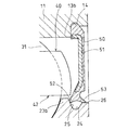
図2に示すように、シール部材50は、固定輪としての外輪11の肩内径面に形成されたシール取付溝14内に外周部が嵌合されて外輪11により支持されている。シール部材50の内周部には、内向きのシールリップ52と外向きのシールリップ53が設けられ、内向きシールリップ52の先端部は、内輪21の肩外径面に形成されたシール溝24の内壁面25にアキシャル接触し、一方、外向きシールリップ53の先端部は、シール溝24の軸方向外方に形成された円筒面26にラジアル接触して、軸受空間を密閉している。
As shown in FIG. 2, the
シールリップ52、53のそれぞれは、回転側の内輪21との接触により早期に摩耗する高摩耗材で形成されている。
Each of the
ここで、高摩耗材とは、深みぞ玉軸受Aを、鉱油系オイルによるオイル潤滑状態において、回転速度;4000rpm、軸受温度;30℃、回転トルク;0.075N・mの運転条件下で回転させ、その回転開始から60分以内のならし運転程度で摩耗して、内輪21に対して非接触となるか、または、接触圧が零とみなせる程度の軽接触となる材料をいい、ゴムからなるものであってもよく、合成樹脂からなるものであってもよい。
Here, the high wear material means that the deep groove ball bearing A is rotated under an operating condition of a rotational speed: 4000 rpm, a bearing temperature: 30 ° C., a rotational torque: 0.075 N · m in an oil lubrication state with mineral oil. It is a material that wears in the run-in period of 60 minutes or less from the start of rotation and is not in contact with the
図2では、シールリップ52、53の全体を高摩耗材で形成しているが、先端部のみを高摩耗材で形成するようにしてもよい。
In FIG. 2, the
実施の形態で示す深みぞ玉軸受のように、軸受空間の開口部内にシール部材50を組込み、そのシール部材50の内周に形成された内向きシールリップ52の先端部をシール溝24の内壁面25に弾性接触させ、外向きシールリップ53をシール溝24の軸方向外方に形成された円筒状周面としての円筒面26に弾性接触させて、軸受空間の開口部を密閉することにより、そのシール部材50によって潤滑オイルに混入するギヤ摩耗粉等の異物が軸受内部に侵入するのを防止することができる。
Like the deep groove ball bearing shown in the embodiment, the
ここで、シールリップ52、53が内輪21と常に弾性接触する状態にあると、その接触抵抗が回転抵抗となってトルク損失が生じることになる。しかし、実施の形態においては、シールリップ52、53のそれぞれを高摩耗材により形成しているため、運転初期に接触タイプであったシールリップ52、53の先端部は、内輪21との接触により早期に摩耗することになる。図3は、シールリップ52、53が摩耗して、シール溝24の内壁面25との間、および円筒面26との間で微細なラビリンス隙間55を形成する非接触の状態を示しているが、接触圧が零と見なせる程度の軽接触の状態となる場合もある。
Here, if the
このように、シールリップ52、53は、運転初期に早期に摩耗して非接触の状態となり、あるいは、接触圧が零と見なせる程度の軽接触の状態となるため、トルク損失を低減する状態で異物の侵入を防止することができ、異物の噛み込みによる損傷の発生を防止し、大きなスラスト力を受けることができる深みぞ玉軸受の寿命の低下を抑制することができる。
As described above, the
図2では、シール部材50の内周に形成された内向きシールリップ52をシール溝24の内壁面25にアキシャル接触させるようにしたが、図4に示すように、内向きシールリップ52および外向きシールリップ53のそれぞれ先端部を内輪21の円筒状周面としての肩外径面27に弾性接触させるようにしてもよい。
In FIG. 2, the
図5は、実施の形態で示す深みぞ玉軸受Aを用いて従動側のヘリカルギヤ60を支持するシャフト61を回転自在に支持した軸受装置を示す。この場合、深みぞ玉軸受Aは、内輪21のスラスト負荷側の肩23bがヘリカルギヤ60側に位置する組付けとする。また、深みぞ玉軸受Aは、一部が油浴に浸かる組付けとする。
FIG. 5 shows a bearing device that rotatably supports a
上記軸受装置において、駆動側ヘリカルギヤ62から従動側ヘリカルギヤ60に回転を伝達すると、シャフト61にスラスト力が負荷され、そのスラスト力は深みぞ玉軸受Aにおける内輪21のスラスト負荷側の肩23bと外輪11のスラスト負荷側の肩13aで支持される。
In the bearing device, when the rotation is transmitted from the driving side
このとき、ボール31にもスラスト力が負荷され、内輪21のスラスト負荷側の肩23bと外輪11のスラスト負荷側の肩13aが必要以上に低い場合、ボール31が肩13a、23bに乗り上がり、肩13a、23bのエッジを損傷させる可能性がある。
At this time, a thrust force is also applied to the
実施の形態では、ボール31の球径dに対する肩高さH1の比率H1/dを0.25以上としているため、ボール31の乗り上げを確実に阻止することができる。
In the embodiment, since the ratio H 1 / d of the shoulder height H 1 to the ball diameter d of the
実施の形態では、深みぞ玉軸受が内輪回転使用のものであるため、シールリップ52、53を内輪21に弾性接触させるようにしたが、外輪回転使用の深みぞ玉軸受においては、シールリップ52、53を外輪11に弾性接触させるようにする。
In the embodiment, since the deep groove ball bearing is for inner ring rotation, the
11 外輪(外方軌道輪)
12 軌道溝
13a 肩
13b 肩
21 内輪(内方軌道輪)
22 軌道溝
23a 肩
23b 肩
24 シール溝
25 内壁面
26 円筒面(円筒状周面)
27 肩外径面(円筒状周面)
31 ボール
40 保持器
50 シール部材
52 内向きシールリップ
53 外向きシールリップ
60 ヘリカルギヤ
61 シャフト
A 深みぞ玉軸受
11 Outer ring (outer raceway ring)
12
22
27 Shoulder outer diameter surface (cylindrical peripheral surface)
31
Claims (4)
前記外方軌道輪と前記内方軌道輪の対向面間に形成された軸受空間の両端開口部内にシール部材を組込んで固定側の軌道輪で支持し、そのシール部材には回転側の軌道輪に弾性接触して軸受空間の両端開口を密閉するシールリップを設け、そのシールリップの少なくとも先端部を、回転側の軌道輪との接触により摩耗して非接触となるか、または、接触圧が零とみなせる程度の軽接触となる高摩耗材で形成し、前記シールリップが、回転側軌道輪の円筒状周面に弾性接触するラジアル接触とされたことを特徴とする深みぞ玉軸受。 An outer race having a raceway groove on the inner diameter surface, an inner race having a raceway groove on the outer diameter surface, a ball incorporated between the raceway groove of the outer raceway and the raceway groove of the inner raceway, A retainer for holding the ball, and the height of at least one of the shoulder on one side of the raceway groove on the outer raceway and the shoulder on the other side of the raceway groove on the inner raceway is set to the outer side. When the height of the shoulder on the other side of the raceway and the shoulder on one side of the inner raceway is higher, the shoulder height of the higher shoulder is H1, and the ball diameter is d, the ball ball The ratio H1 / d of the shoulder height H1 to the diameter d is in the range of 0.25 to 0.50, and one of the outer race ring and the inner race ring is used as the fixed side, and the other is used as the rotation side. In deep groove ball bearings,
A seal member is incorporated into both end openings of a bearing space formed between the opposing surfaces of the outer race ring and the inner race ring, and is supported by a fixed race ring. A seal lip that elastically contacts the ring and seals both end openings of the bearing space is provided, and at least the tip of the seal lip is worn out by contact with the raceway on the rotating side and becomes non-contact or contact pressure A deep groove ball bearing, characterized in that it is made of a high wear material that is light contact that can be regarded as zero, and the seal lip is a radial contact that elastically contacts the cylindrical peripheral surface of the rotating raceway .
前記一対の転がり軸受が、請求項1乃至3のいずれかの項に記載の深みぞ玉軸受からなることを特徴とする軸受装置。 In a bearing device in which a shaft provided with a helical gear is rotatably supported by a pair of rolling bearings partially immersed in an oil bath,
The bearing device, wherein the pair of rolling bearings comprises the deep groove ball bearing according to any one of claims 1 to 3 .
Priority Applications (1)
| Application Number | Priority Date | Filing Date | Title |
|---|---|---|---|
| JP2012006915A JP6050000B2 (en) | 2012-01-17 | 2012-01-17 | Deep groove ball bearing and bearing device |
Applications Claiming Priority (1)
| Application Number | Priority Date | Filing Date | Title |
|---|---|---|---|
| JP2012006915A JP6050000B2 (en) | 2012-01-17 | 2012-01-17 | Deep groove ball bearing and bearing device |
Publications (2)
| Publication Number | Publication Date |
|---|---|
| JP2013148115A JP2013148115A (en) | 2013-08-01 |
| JP6050000B2 true JP6050000B2 (en) | 2016-12-21 |
Family
ID=49045806
Family Applications (1)
| Application Number | Title | Priority Date | Filing Date |
|---|---|---|---|
| JP2012006915A Expired - Fee Related JP6050000B2 (en) | 2012-01-17 | 2012-01-17 | Deep groove ball bearing and bearing device |
Country Status (1)
| Country | Link |
|---|---|
| JP (1) | JP6050000B2 (en) |
Families Citing this family (2)
| Publication number | Priority date | Publication date | Assignee | Title |
|---|---|---|---|---|
| CN103742543B (en) * | 2013-12-18 | 2017-01-18 | 宁波摩盛轴承有限公司 | Bearing seal device |
| JP2015132288A (en) * | 2014-01-10 | 2015-07-23 | Ntn株式会社 | Ball bearing |
Family Cites Families (8)
| Publication number | Priority date | Publication date | Assignee | Title |
|---|---|---|---|---|
| JP2566748Y2 (en) * | 1992-01-31 | 1998-03-30 | 日本精工株式会社 | Sealed deep groove ball bearings for cell motors |
| JP2000145795A (en) * | 1998-11-06 | 2000-05-26 | Ntn Corp | Deep groove ball bearing |
| JP2003287040A (en) * | 2002-03-28 | 2003-10-10 | Nsk Ltd | Rolling bearing with sealing seal |
| JP2004211862A (en) * | 2003-01-08 | 2004-07-29 | Koyo Seiko Co Ltd | Pulley supporting device |
| JP5455334B2 (en) * | 2008-07-09 | 2014-03-26 | Ntn株式会社 | Sealed bearing |
| JP2011007288A (en) * | 2009-06-26 | 2011-01-13 | Ntn Corp | Deep groove ball bearing and gear support device |
| JP2011127702A (en) * | 2009-12-18 | 2011-06-30 | Ntn Corp | Rolling bearing |
| JP2011163395A (en) * | 2010-02-05 | 2011-08-25 | Toyota Motor Corp | Oil supply device |
-
2012
- 2012-01-17 JP JP2012006915A patent/JP6050000B2/en not_active Expired - Fee Related
Also Published As
| Publication number | Publication date |
|---|---|
| JP2013148115A (en) | 2013-08-01 |
Similar Documents
| Publication | Publication Date | Title |
|---|---|---|
| JP5870563B2 (en) | Roller bearing cage and rolling bearing | |
| WO2010150707A1 (en) | Synthetic resin holder for deep groove ball bearings, deep groove ball bearing, and gear supporting device | |
| JP2007032612A (en) | Roller bearing | |
| JP2014231856A (en) | Rolling bearing | |
| JP2012041940A (en) | Retainer of cylindrical roller bearing and cylindrical roller bearing | |
| JP6234137B2 (en) | Deep groove ball bearing | |
| JP2010019296A (en) | Bearing with seal | |
| JP6050000B2 (en) | Deep groove ball bearing and bearing device | |
| JP2020041659A (en) | Ball bearing | |
| JP2017190874A (en) | Deep groove ball bearing and bearing device | |
| JP2008261478A (en) | Radial ball bearing cage and radial ball bearing | |
| JP2013092241A (en) | Deep groove ball bearing and bearing device | |
| JP6267851B2 (en) | Deep groove ball bearing and bearing device | |
| JP5376310B2 (en) | Synthetic resin cage and deep groove ball bearing for deep groove ball bearings | |
| JP6537297B2 (en) | Deep groove ball bearings | |
| JP2005003198A (en) | Rolling bearing and transmission for hybrid car or fuel cell car using the same | |
| JP2013072451A (en) | Deep groove ball bearing and bearing device | |
| WO2013012357A1 (en) | Bearing unit | |
| JPH10274243A (en) | Rolling bearing device equipped with oil supplying means | |
| JP5050910B2 (en) | Ball bearing cage and ball bearing | |
| JP2009168171A (en) | Roller bearing | |
| JP5012383B2 (en) | Radial roller bearing with cage | |
| JP2011196393A (en) | Thrust roller bearing | |
| JP2009092158A (en) | Rolling bearing | |
| JP5012500B2 (en) | Deep groove ball bearing |
Legal Events
| Date | Code | Title | Description |
|---|---|---|---|
| A621 | Written request for application examination |
Free format text: JAPANESE INTERMEDIATE CODE: A621 Effective date: 20141104 |
|
| A131 | Notification of reasons for refusal |
Free format text: JAPANESE INTERMEDIATE CODE: A131 Effective date: 20150818 |
|
| A977 | Report on retrieval |
Free format text: JAPANESE INTERMEDIATE CODE: A971007 Effective date: 20150820 |
|
| A521 | Request for written amendment filed |
Free format text: JAPANESE INTERMEDIATE CODE: A523 Effective date: 20151015 |
|
| A131 | Notification of reasons for refusal |
Free format text: JAPANESE INTERMEDIATE CODE: A131 Effective date: 20160329 |
|
| A521 | Request for written amendment filed |
Free format text: JAPANESE INTERMEDIATE CODE: A523 Effective date: 20160530 |
|
| TRDD | Decision of grant or rejection written | ||
| A01 | Written decision to grant a patent or to grant a registration (utility model) |
Free format text: JAPANESE INTERMEDIATE CODE: A01 Effective date: 20161108 |
|
| A61 | First payment of annual fees (during grant procedure) |
Free format text: JAPANESE INTERMEDIATE CODE: A61 Effective date: 20161124 |
|
| R150 | Certificate of patent or registration of utility model |
Ref document number: 6050000 Country of ref document: JP Free format text: JAPANESE INTERMEDIATE CODE: R150 |
|
| R250 | Receipt of annual fees |
Free format text: JAPANESE INTERMEDIATE CODE: R250 |
|
| R250 | Receipt of annual fees |
Free format text: JAPANESE INTERMEDIATE CODE: R250 |
|
| R250 | Receipt of annual fees |
Free format text: JAPANESE INTERMEDIATE CODE: R250 |
|
| LAPS | Cancellation because of no payment of annual fees |