JP6049952B2 - Device for removing oil mist and odor from air flow - Google Patents
Device for removing oil mist and odor from air flow Download PDFInfo
- Publication number
- JP6049952B2 JP6049952B2 JP2016534700A JP2016534700A JP6049952B2 JP 6049952 B2 JP6049952 B2 JP 6049952B2 JP 2016534700 A JP2016534700 A JP 2016534700A JP 2016534700 A JP2016534700 A JP 2016534700A JP 6049952 B2 JP6049952 B2 JP 6049952B2
- Authority
- JP
- Japan
- Prior art keywords
- filter
- base
- odor
- oil mist
- air flow
- Prior art date
- Legal status (The legal status is an assumption and is not a legal conclusion. Google has not performed a legal analysis and makes no representation as to the accuracy of the status listed.)
- Active
Links
- 239000003595 mist Substances 0.000 title claims description 25
- 239000013013 elastic material Substances 0.000 claims description 2
- 230000007246 mechanism Effects 0.000 description 32
- 235000019645 odor Nutrition 0.000 description 11
- 230000001954 sterilising effect Effects 0.000 description 9
- 238000004659 sterilization and disinfection Methods 0.000 description 9
- 239000000463 material Substances 0.000 description 8
- OKTJSMMVPCPJKN-UHFFFAOYSA-N Carbon Chemical compound [C] OKTJSMMVPCPJKN-UHFFFAOYSA-N 0.000 description 2
- 230000005484 gravity Effects 0.000 description 2
- 230000004048 modification Effects 0.000 description 2
- 238000012986 modification Methods 0.000 description 2
- 238000011144 upstream manufacturing Methods 0.000 description 2
- 239000005539 carbonized material Substances 0.000 description 1
- 238000010586 diagram Methods 0.000 description 1
- 239000000428 dust Substances 0.000 description 1
- 239000007788 liquid Substances 0.000 description 1
- 238000004519 manufacturing process Methods 0.000 description 1
- 229920000642 polymer Polymers 0.000 description 1
- 239000002861 polymer material Substances 0.000 description 1
- 230000000717 retained effect Effects 0.000 description 1
- 239000000126 substance Substances 0.000 description 1
Images


Classifications
-
- B—PERFORMING OPERATIONS; TRANSPORTING
- B01—PHYSICAL OR CHEMICAL PROCESSES OR APPARATUS IN GENERAL
- B01D—SEPARATION
- B01D46/00—Filters or filtering processes specially modified for separating dispersed particles from gases or vapours
- B01D46/56—Filters or filtering processes specially modified for separating dispersed particles from gases or vapours with multiple filtering elements, characterised by their mutual disposition
- B01D46/62—Filters or filtering processes specially modified for separating dispersed particles from gases or vapours with multiple filtering elements, characterised by their mutual disposition connected in series
- B01D46/64—Filters or filtering processes specially modified for separating dispersed particles from gases or vapours with multiple filtering elements, characterised by their mutual disposition connected in series arranged concentrically or coaxially
-
- B—PERFORMING OPERATIONS; TRANSPORTING
- B01—PHYSICAL OR CHEMICAL PROCESSES OR APPARATUS IN GENERAL
- B01D—SEPARATION
- B01D46/00—Filters or filtering processes specially modified for separating dispersed particles from gases or vapours
- B01D46/0027—Filters or filtering processes specially modified for separating dispersed particles from gases or vapours with additional separating or treating functions
- B01D46/003—Filters or filtering processes specially modified for separating dispersed particles from gases or vapours with additional separating or treating functions including coalescing means for the separation of liquid
- B01D46/0031—Filters or filtering processes specially modified for separating dispersed particles from gases or vapours with additional separating or treating functions including coalescing means for the separation of liquid with collecting, draining means
-
- B—PERFORMING OPERATIONS; TRANSPORTING
- B01—PHYSICAL OR CHEMICAL PROCESSES OR APPARATUS IN GENERAL
- B01D—SEPARATION
- B01D46/00—Filters or filtering processes specially modified for separating dispersed particles from gases or vapours
- B01D46/0027—Filters or filtering processes specially modified for separating dispersed particles from gases or vapours with additional separating or treating functions
- B01D46/0038—Filters or filtering processes specially modified for separating dispersed particles from gases or vapours with additional separating or treating functions with means for influencing the odor, e.g. deodorizing substances
-
- B—PERFORMING OPERATIONS; TRANSPORTING
- B01—PHYSICAL OR CHEMICAL PROCESSES OR APPARATUS IN GENERAL
- B01D—SEPARATION
- B01D46/00—Filters or filtering processes specially modified for separating dispersed particles from gases or vapours
- B01D46/24—Particle separators, e.g. dust precipitators, using rigid hollow filter bodies
- B01D46/2403—Particle separators, e.g. dust precipitators, using rigid hollow filter bodies characterised by the physical shape or structure of the filtering element
- B01D46/2411—Filter cartridges
Description
本発明は、大まかには空気流からオイルミストおよび臭気を取り除くための器具に関するものであり、より具体的には、空気流からオイルミストおよび臭気を取り除くためのコンパクトなフィルタ機構に関するものである。本発明は具体的には内部に真空ポンプを有する低温滅菌器に用いることができ、特にこれについて説明する。ただし、開示のこのフィルタ機構は、空気流のオイルミストを取り除くための他の利用法もある。 The present invention relates generally to an apparatus for removing oil mist and odor from an air stream, and more specifically to a compact filter mechanism for removing oil mist and odor from an air stream. Specifically, the present invention can be used in a pasteurizer having a vacuum pump therein, and this will be described in particular. However, the disclosed filter mechanism has other uses for removing oil mist from the airflow.
典型的には、低温滅菌器は真空条件下でチャンバ内の物品を滅菌する。液体滅菌剤がそのチャンバ内に注入されて蒸気化し、滅菌される物品を、蒸気化された滅菌剤によって包み、行き渡らせる。こうした滅菌器は、チャンバ内に真空引きを行うための真空ポンプを有している。この真空ポンプの動作中、オイルミストおよびその他の塵埃はチャンバから吸引され、真空チャンバの出口ポートから排出される。従来、真空ポンプが生じさせる空気流を周囲環境へ放出させるに先立ってその空気流からオイルおよびその他の物質を濾過するために、真空ポンプの出口ポートに複雑な機構が設けられる。排出される空気から臭気を取り除くため、オイルミスト除去器の下流に別個のフィルタ機構が設けられる。 Typically, a pasteurizer sterilizes items in a chamber under vacuum conditions. Liquid sterilant is injected into the chamber and vaporized, and the article to be sterilized is wrapped and spread with the vaporized sterilant. Such a sterilizer has a vacuum pump for evacuating the chamber. During operation of this vacuum pump, oil mist and other dust is sucked from the chamber and discharged from the outlet port of the vacuum chamber. Conventionally, a complex mechanism is provided at the outlet port of the vacuum pump to filter oil and other materials from the air flow generated by the vacuum pump prior to releasing it to the surrounding environment. In order to remove odors from the exhausted air, a separate filter mechanism is provided downstream of the oil mist remover.
こうした機構は場所をとるばかりか、組み立ておよび製品寿命にわたるメンテナンスが困難かつ高くつく。 These mechanisms not only take up space, but are difficult and expensive to assemble and maintain over the life of the product.
本発明はこうした問題点やその他の問題点を克服し、空気流から、より具体的には低温滅菌器で用いられる真空ポンプの排気から、オイルミストおよび臭気を取り除くためのフィルタ機構を提供する。 The present invention overcomes these and other problems and provides a filter mechanism for removing oil mist and odor from an air stream, more specifically from the exhaust of a vacuum pump used in a low temperature sterilizer.
本発明の好ましい実施形態の一例によれば、空気流を取り入れるための空気入口部を自身の下方端に有するベースを備えた、空気流からオイルミストおよび臭気を取り除くための装置が提供される。第1の筒状フィルタが、第1の端部と第2の端部を有する。第1の端部は閉じていて、第2の端部はベースに載せられており、第1の筒状フィルタは空気入口部に通じる内方チャンバを画定する。ベースには第2の筒状フィルタが載せられる。第2の筒状フィルタは第1の筒状フィルタを取り巻いており、第1の筒状フィルタとの間に外方チャンバを画定する。ベースを貫いて開口が形成されている。この開口は外方チャンバを空気入口部に繋ぐ。ベース内に弁体が配置される。この弁体は、外方チャンバ内の圧力が空気入口部内の圧力を上回った場合に外方チャンバから空気入口部に向かう流れを通す。 According to an example of a preferred embodiment of the present invention, there is provided an apparatus for removing oil mist and odor from an air stream, with a base having an air inlet at its lower end for taking in the air stream. The first tubular filter has a first end and a second end. The first end is closed and the second end rests on the base, and the first tubular filter defines an inner chamber that leads to the air inlet. A second cylindrical filter is placed on the base. The second cylindrical filter surrounds the first cylindrical filter and defines an outer chamber with the first cylindrical filter. An opening is formed through the base. This opening connects the outer chamber to the air inlet. A valve body is disposed in the base. The valve body allows a flow from the outer chamber toward the air inlet when the pressure in the outer chamber exceeds the pressure in the air inlet.
本発明の利点の一つは、空気流からオイルミストおよび臭気を取り除くためのフィルタ機構を提供することにある。 One of the advantages of the present invention is to provide a filter mechanism for removing oil mist and odor from an air stream.
本発明のもう一つの利点は、上記のようなフィルタ機構はコンパクトかつ効率的だということにある。 Another advantage of the present invention is that the filter mechanism as described above is compact and efficient.
本発明のさらなる利点は、上記のようなフィルタ機構においては空気流から取り除かれたオイルが真空ポンプへ戻されるということにある。 A further advantage of the present invention is that the oil removed from the air stream is returned to the vacuum pump in the filter mechanism as described above.
本発明の他の利点は、上記のようなフィルタ機構は空気流に対する抵抗を増加させないということにある。 Another advantage of the present invention is that such a filter mechanism does not increase the resistance to air flow.
本発明のさらなる利点は、上記のようなフィルタ機構は構造が単純で組み立ておよびメンテナンスが容易ということにある。 A further advantage of the present invention is that the filter mechanism as described above is simple in structure and easy to assemble and maintain.
本発明のさらなる利点は、上記のようなフィルタ機構は、フィルタに集められたオイルをフィルタ機構の上流側の装置へ戻すのに弁機構を利用するということにある。 A further advantage of the present invention is that the filter mechanism as described above utilizes a valve mechanism to return the oil collected in the filter to a device upstream of the filter mechanism.
本発明のさらなる利点は、上記のようなフィルタ機構において弁手段が傘型弁で構成されるということにある。 A further advantage of the present invention is that the valve means is constituted by an umbrella-type valve in the filter mechanism as described above.
これらの利点およびその他の利点は、以下における好ましい実施形態の説明と付随の図面および添付の特許請求の範囲を総合して明らかとなる。 These and other advantages will be apparent from the following description of the preferred embodiment and the accompanying drawings and appended claims.
本発明の特定の部品および部品配置について物理的形態をとることがあり、好ましい実施形態の一例が本明細書にて詳細に説明され、また本明細書の一部を形成する付随の図面にて図示される。
本発明の好ましい実施形態の一例を図示することのみを目的としており本発明を限定する意図のない図面をここで参照してみると、図1は、物品(図示せず)が滅菌される滅菌チャンバ12を有する低温滅菌器10(仮想線で示す)を概略的に図示している。滅菌チャンバ12は、滅菌サイクル中に滅菌チャンバ12内で真空を発生させるよう動作可能な真空ポンプ14に通じている。入口導管16が滅菌チャンバ12を真空ポンプ14の入口へ繋いでいる。出口導管18が、真空ポンプ14の出口を、滅菌サイクル中に滅菌チャンバ12より排出された空気からオイルミストを取り除くためのコンパクトなフィルタ機構30へと繋いでいる。
Referring now to the drawings, which are intended only to illustrate an example of a preferred embodiment of the invention and are not intended to limit the invention, FIG. 1 illustrates sterilization in which an article (not shown) is sterilized. 1 schematically illustrates a pasteurizer 10 (shown in phantom) having a
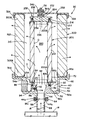
出口導管18の開放端は、図2および図4に示されている、外向きに広がったフランジ18aを有している。フィルタ機構30は基本的には、真空ポンプ14が発生させる空気流からオイルミストを取り除くための内方フィルタ200、および、内方フィルタ200を取り巻いていて真空ポンプ14が発生させる空気流から臭気を取り除くための外方フィルタ300から成る。内方フィルタ200と外方フィルタ300はどちらもベース40に支持されている。
The open end of the
ベース40は、椀状部42と、椀状部42の下方から延びる筒状のスタック部44と、椀状部42の上端から外方へ広がるフランジ部46とから成る。
The
ベース40の椀状部42は、平坦で円形状の底壁52と、底壁52の周縁から上方に延びる円筒状側壁54を有する。側壁54は、側壁54の厚みが大きくなっている部位54a(図2において最も良く表れている)を有する。
The
スタック部44は、底壁52の下側つまり底面から下方へ延びている。ここで示す実施形態においては、筒状のスタック部44は形状としては円筒状で、自身を通り抜ける円筒状の穴あるいは通路58を画定している。下方の、スタック部44の開放端は、外方に広がった小さなフランジ44aを有する。スタック部44のこの外向きに広がったフランジ44aは、真空ポンプ14からの出口導管18のフランジ18aと一致するように寸法決めされている。図4で最もよく表れているように、スタック部44のフランジ44aと、真空ポンプ14からの出口導管18のフランジ18aはそれぞれ、環状の溝を有しており、この溝はそれぞれ44bおよび18bと付番されている。環状の溝18b,44bは互いに向かい合うように、そしてその中にOリング62を受容するよう寸法決めされている。図面中に示すように、ベース40のスタック部44および出口導管18にあるフランジ44a,18aは互いに一致して係合するよう設計されており、フィルタ機構30が環状クランプ具64によって従来知られているように出口導管18へと取り付けできるようになっている。図面中に図示されているように、出口導管18を通る通路68は、スタック部44によって画定される通路58と通じている。
The
ベース40のフランジ部46は椀状部42の上端に沿って外向きに広がっており、上向きに延びる環状部あるいは縁部を自身の外方端沿いに有している。図面中に図示されているように、フランジ部46は、外方フィルタ300を受容する寸法となっている平坦な環状の表面46aを定める。
The
椀状部42内で、ハブあるいはボス82が中央部に配置されている。ハブ82は底壁52の上面に形成されている。ハブ82は概ね円筒状の形状をしており、その上端には減直径部84を有している。減直径部84はハブ82の上端で段状部あるいは切り欠き部86を画定する。ハブ82は円筒状の外表面82aと円錐状の内表面82bを有している。ハブ82の外表面82aと円筒状側壁54の内表面54bとの間に、環状の溝あるいは谷92が形成されている。ハブ82の円錐状の内表面82bは、底壁52を通り抜けて筒状のスタック部44内に形成された円筒状経路58に通じる、円錐状の開口あるいは通路88を画定する。
A hub or
図2に最も良く表れているように、ハブ82の外表面82aには、椀状部42の底壁52近くに、窪みあるいは空洞94が形成されている。
As best shown in FIG. 2, a recess or
2つの相隔てられた開口112,114がハブ82を貫いて形成されており、溝92をハブ82の円錐状内表面82bと繋いでいる。ここで示す実施形態においては、開口112,114はハブ82を概ね水平に貫いて延びており、開口112は開口114の上方に設けられている。上方の開口112は弁体120を受容するよう寸法決めされている。下方の開口114は溝92の下部領域と繋がるように設けられている。
Two spaced apart
ここで示す実施形態においては、弁体120は弾力性のあるポリマーまたは弾性材料で形成された傘型弁である。弁体120は円形状部分122を有しており、図4において最も良く表れているように、この部分はハブ82の円錐状内表面82bによって画定されている円錐状の通路88内に配置されて、開口114に重なる、または覆うように寸法決めされている。弁体120はさらに柄部分124を有しており、これは弁体120の円形状部分122から延びている。図示のように、柄部分124は頸環部あるいは肥大部126を有している。ここで、ハブ82と開口112は、空洞94によって画定される端壁に柄部分124の肥大部126を隣接させながら柄部分124が開口112を通って延びることができるように寸法決めされている。
In the embodiment shown here, the
好ましい実施形態においては、弁体120は、オハイオ州クリーブランドのMinivalve Inc.により品番UM18.0001-152.01として販売されている傘型弁である。
In the preferred embodiment, the
図4に最も良く表れているように、開口114はハブ82の内表面82bによって画定される円錐状の通路88と繋がっており、弁体120の円形状部分122は、開口112に配置されたときに開口114を覆う。ベース40の椀状部42の側壁54にある厚み部位54aに、ネジ筋付き開口132が形成されている。ネジ筋付き開口132は、ハブ82の空洞94と、概ね向かい合う、つまり一直線に並んでいる。図4に図示されているように、ネジ筋付き開口132は従来のネジ筋付きプラグ134を受容するように寸法決めされている。
As best seen in FIG. 4, the
図3に最も良く表れているように、椀状部42内には2つの相隔てられたブロック部またはサポート部142,144が形成されている。ブロック部またはサポート部142,144は、底壁52の内表面52aおよび側壁54の内表面54bから延びている。ブロック部142,144は、ハブ82のうち向かい合う面に配置されている。図面中に示すように、ブロック部142,144には、ベース40から上方へ延びるネジ筋付きの細長い棒材152,154を受容するネジ筋付き穴が形成されている。以下にてより詳しく説明するように、棒材152,154の端部にはネジ筋が付けられている。
As best shown in FIG. 3, two spaced block portions or
内方フィルタ200は細長い筒状の部材である。ここで示す実施形態においては、内方フィルタ200は円筒状の形状で、筒状フィルタ材212を有しており、筒状フィルタ材212の端部には環状のカラーまたはリング214を備えている。各カラー214の一方の面は、筒状フィルタ材212の一端を受容するように寸法決めされた環状の溝を画定する。カラー214の他方の面は、円筒状の壁216の形状になっている。カラー214の壁216は、ハブ82の減直径部84を受容するように寸法決めされている。図3に最も良く表れているように、カラー214の壁部分216は、Oリング218を受容する寸法の切り欠き付き角部を有しており、このOリングは内方フィルタ200のカラー214をハブ82に対して封止する。内方フィルタ200には第1の端部200Aと第2の端部200Bがある。第1の端部200Aはベース40のハブ82と接続しており、第2の端部200Bはその上方に位置する。内方フィルタ200の第2の端部200Bの上に置かれるように、キャップ232が寸法決めされている。キャップ232は中央に位置する円筒状部分234を有しており、これは、内方フィルタ200の第2の端部200Bに付いているカラー214の壁216内に収まる寸法となっている。キャップ232の円筒状部分234と、内方フィルタ200のカラー214の壁216との間に、Oリング236が配置される。キャップ232は、外向きに広がる翼部242,244をキャップ232の両側に備えている。翼部242,244のそれぞれには開口246が形成されている。開口246は、自身を貫く細長い棒材152,154のネジ筋付き端部を受け入れるように寸法決めおよび位置決めされている。刻み付き固定材252が、細長い棒材152,154の端部にネジ合わされて、ワッシャ254と共にキャップ232を内方フィルタ200の第2の端部200B上に締め付け、内方フィルタ200をベース40上に押し付けおよび締め付ける。
The
外方フィルタ300はベース40のフランジ部46上に配置される寸法になっている。図面中に示すように、外方フィルタ300は内方フィルタ200から距離を置いており、内方フィルタ200と外方フィルタ300との間に環状チャンバ310を画定するようになっている。ここで示す実施形態においては、外方フィルタ300は円筒状の形状であり、フィルタ材322を有している。フィルタ材322の端部のそれぞれに端部キャップ324が設けられる。外方フィルタ300の第1の端部300Aは、上方に面を向けているベース40のフランジ部46の環状の表面46a上に載る寸法となっている。円形状のカバー332が、外方フィルタ300の第2の端部300Bを覆って配置されるよう寸法決めされている。カバー332は、下方に延びる縁部または壁部334を有しており、これは外方フィルタ300の端部を捉えるようになっている。カバー332はさらに、相隔てられた開口336を有しており、これらは自身を通してネジ筋付き棒材152,154の端部を受け入れるよう寸法決めおよび配置されている。刻み付き固定具342がネジ筋付き棒材152,154の端部にネジ留めされてカバー332を外方フィルタ300上に締め付けており、これによりベース40に外方フィルタ300を締め付ける。ガスケット344が固定具342とカバー332との間に配置されていて、これら同士の間の封止を行うようになっている。
The
図面中に示すように、内方フィルタ200は円筒状の内方チャンバ260を画定しており、このチャンバは、ハブ82を貫く円錐状の通路88と、ベース40のスタック部44を貫く円筒状の通路58と、真空ポンプ14の出口導管18への円筒状開口68と、に繋がっている。
As shown in the drawings, the
好ましい実施形態においては、内方フィルタ20は、マサチューセッツ州ヒンガンのAlcatel Vacuum Products Inc.によりカタログNo.112453として販売されているフィルタから成る。 In the preferred embodiment, the inner filter 20 comprises a filter sold as Catalog No. 112453 by Alcatel Vacuum Products Inc. of Hingan, Massachusetts.
外方フィルタ300は全体として、自身を通り抜ける空気から臭気を取り除く活性炭から成る。好ましい実施形態においては、外方フィルタ300は、イリノイ州アイタスカのSolberg Manufacturing Inc.により品番3167-EL-02-SD 18483として販売されているフィルタである。
The
ここでフィルタ機構30の働きについて見ると、図4において最も良く表れているように、フィルタ機構30は環状クランプ具64によって真空ポンプ14の出口導管18に取り付けられている。このため、フィルタ機構30は概ね鉛直向きに配置されており、内方および外方フィルタ200,300の軸は概ね鉛直である。真空ポンプ14の動作中、圧力つまり真空ポンプの出力を受けた空気流は、内方フィルタ200の内方チャンバ260へと流れ込む。滅菌チャンバから送り出される空気流内のオイルその他の物質は、内方フィルタ200によって濾過され、ほとんどは内方フィルタ200によって画定される内方チャンバ260内に閉じ込められる。内方フィルタ200を通り抜けて濾過された空気は、内方フィルタ200と外方フィルタ300との間に画定された環状チャンバ310に入る。内方フィルタ200によって分離されたオイルは、図4内で液滴“D”として図示されているように、内方チャンバ260内に留まる。このため、真空ポンプ14により生じる空気流内のオイルミストの大部分は、フィルタ機構30の内方チャンバ260内に留められる。図4にて図示されているように、いくらかのオイルは内方フィルタ200をくぐり抜けて内方フィルタ200の外表面に結集することがある。主に内方フィルタ200の外表面に沿って結集するオイル液滴“D”は、図4に図示されているように、ベース40に形成された環状の溝92へと重力によって流れていく。
Looking at the function of the
内方フィルタ200によって濾過された空気は、外方フィルタ300へ向けて外方の環状チャンバ310に入らねばならない。上記にて示したように、外方フィルタ300は好ましくは炭化物質あるいはその他類似の、空気流から臭気を取り除く物質で形成される。濾過される空気は、内方フィルタ200および外方フィルタ300で濾過された後、次いで周囲環境へと放出される。
Air filtered by the
真空ポンプ14の動作中、内方フィルタ200で画定される内方チャンバ260と外方フィルタ300で画定される外方の環状チャンバ310の内部には圧力がある。内方フィルタ200内部の圧力は外方の環状チャンバ310内の圧力よりも大きいことが理解されよう。結果として、内方チャンバ260内の圧力は、弁体120の円形状部分122をハブ82の内表面82bに押し付いたままとし、これによりハブ82の側壁を貫いて形成されている開口114を遮蔽および封止する。このようにして、真空ポンプ14によって生じる空気流はフィルタ機構30の外方の環状チャンバ310へ到達する前に内方フィルタ200のフィルタ材を通り抜けなければならないことが保証される。
During operation of the
内方フィルタ200によって空気流から濾過されたオイルは、内方フィルタ200の内表面に沿ってベース40の漏斗状通路88へと流れ落ち、出口導管18の通路58を通って真空ポンプ14へと戻される。空気流内のオイルミストのほとんどは内方フィルタ200によって濾過されることが理解されよう。ただし上記にて示したように、いくらかのオイルは内方フィルタ200を強引に通過、つまりくぐり抜けて、環状チャンバ310内で内方フィルタ200の外表面に沿って液滴“D”を形成する。図4に図示するように、オイル液滴“D”は下方へ流れ出て、環状の溝92内でオイル溜り“P”を形成する。
The oil filtered from the air flow by the
真空ポンプ14が動作していない期間中は、環状の溝92内のオイルの圧力が通路88内の圧力よりも大きい場合、ベース40の環状の溝92内に回収されたオイルは重力によってベース40の通路88内に逆流できるようになっている。言い換えると、環状チャンバ310内に回収されたオイルは、環状チャンバ310内の圧力が内方チャンバ260内の圧力を上回っている場合に内方チャンバ260を通って真空ポンプ14へと逆流出することができる。
During a period when the
このようにして本発明は、真空ポンプからのオイルミストおよび臭気を取り除くためのコンパクトなフィルタ機構を提供する。本発明はさらに、メンテナンスや清浄が容易なフィルタ機構を提供する。 Thus, the present invention provides a compact filter mechanism for removing oil mist and odor from the vacuum pump. The present invention further provides a filter mechanism that is easy to maintain and clean.
以上の記載は本発明の具体的な実施形態の一例である。この実施形態は例示のために説明されたものに過ぎず、本発明の趣旨および範囲を逸脱しない範囲で当業者により様々な変更および改良がなされてもよいものであると理解されたい。そうしたあらゆる改良および変更は、それが請求項に係る発明あるいはその均等物の範囲にある限り、本発明に含まれるものであることが企図されている。 The above description is an example of a specific embodiment of the present invention. It should be understood that this embodiment has been described for illustrative purposes only, and that various changes and modifications may be made by those skilled in the art without departing from the spirit and scope of the present invention. All such modifications and changes are intended to be included in the present invention so long as they fall within the scope of the claimed invention or equivalents thereof.
Claims (9)
空気流を取り入れるための空気入口部を自身の下方端に有し、前記空気入口部周りに形成された溝を有するベースと、
第1の端部と第2の端部とを有する第1の筒状フィルタであって、前記第1の端部は前記ベースに載せられており、前記空気入口部に通じる内方チャンバを画定し、前記空気流からオイルを濾過するように寸法決めされている第1の筒状フィルタと、
第1の端部と第2の端部とを有する第2の筒状フィルタであって、前記第1の端部は前記ベースに載せられており、前記第1の筒状フィルタを取り巻いており、前記第1の筒状フィルタとの間に前記溝と繋がる外方チャンバを画定し、前記第1の筒状フィルタの下流に配置された第2の筒状フィルタと、
前記ベースを貫く開口であって、前記外方チャンバを前記空気入口部に繋ぐ開口と、
前記ベースの開口内に配置された弁体であって、前記外方チャンバ内の圧力が前記空気入口部内の圧力を上回った場合に前記外方チャンバから前記開口を通って前記空気入口部へ向かう流れを通す弁体と、
前記第1の筒状フィルタの前記第2の端部に取り付けられて前記第2の端部を閉じるキャップと、
前記第2の筒状フィルタの前記第2の端部に取り付けられて前記第2の端部を閉じるカバーと、
前記外方チャンバを通ってそれぞれ延びる少なくとも2本の棒材であって、その少なくとも2本のそれぞれが前記ベースに取り付けられる第1の端部および第2の端部を有する棒材と、
前記第1の筒状フィルタを前記ベースと前記キャップとの間で締め付け、また前記第2の筒状フィルタを前記ベースと前記カバーとの間で締め付けるために、前記少なくとも2本の棒材のそれぞれの前記第2の端部近くに配置される複数の固定材と、
を備えたことを特徴とする、空気流からオイルミストおよび臭気を取り除くための装置。 In a device for removing oil mist and odor from an air stream,
A base having an air inlet at its lower end for taking in an air flow and having a groove formed around the air inlet;
A first tubular filter having a first end and a second end, wherein the first end rests on the base and defines an inner chamber leading to the air inlet. A first tubular filter dimensioned to filter oil from the air stream;
A second cylindrical filter having a first end and a second end, wherein the first end is mounted on the base and surrounds the first cylindrical filter. Defining an outer chamber connected to the groove between the first cylindrical filter and a second cylindrical filter disposed downstream of the first cylindrical filter;
An opening through the base, the opening connecting the outer chamber to the air inlet,
A valve body disposed in an opening of the base, wherein when the pressure in the outer chamber exceeds the pressure in the air inlet portion, the valve is directed from the outer chamber to the air inlet portion through the opening. A valve that passes the flow,
A cap attached to the second end of the first tubular filter and closing the second end;
A cover attached to the second end of the second tubular filter and closing the second end;
At least two bars each extending through the outer chamber, each of which has a first end and a second end attached to the base; and
Each of the at least two bar members for tightening the first tubular filter between the base and the cap and for tightening the second tubular filter between the base and the cover. A plurality of fixing members disposed near the second end of
A device for removing oil mist and odor from an air stream, characterized by comprising:
Applications Claiming Priority (3)
| Application Number | Priority Date | Filing Date | Title |
|---|---|---|---|
| US14/014,874 | 2013-08-30 | ||
| US14/014,874 US9120042B2 (en) | 2013-08-30 | 2013-08-30 | Compact filter assembly for removing oil mist and odor from an airstream |
| PCT/US2014/045546 WO2015030935A1 (en) | 2013-08-30 | 2014-07-07 | Compact filter assembly for removing oil mist and odor from an airstream |
Publications (2)
| Publication Number | Publication Date |
|---|---|
| JP2016529102A JP2016529102A (en) | 2016-09-23 |
| JP6049952B2 true JP6049952B2 (en) | 2016-12-21 |
Family
ID=52581228
Family Applications (1)
| Application Number | Title | Priority Date | Filing Date |
|---|---|---|---|
| JP2016534700A Active JP6049952B2 (en) | 2013-08-30 | 2014-07-07 | Device for removing oil mist and odor from air flow |
Country Status (10)
| Country | Link |
|---|---|
| US (1) | US9120042B2 (en) |
| EP (1) | EP3038734B1 (en) |
| JP (1) | JP6049952B2 (en) |
| CN (1) | CN105592908B (en) |
| AU (1) | AU2014311816B2 (en) |
| BR (1) | BR112016004034B1 (en) |
| CA (1) | CA2920635C (en) |
| ES (1) | ES2706773T3 (en) |
| MX (1) | MX2016002048A (en) |
| WO (1) | WO2015030935A1 (en) |
Families Citing this family (5)
| Publication number | Priority date | Publication date | Assignee | Title |
|---|---|---|---|---|
| US9908070B2 (en) * | 2015-11-23 | 2018-03-06 | Pall Corporation | Fuel tank inerting prefilter assemblies, devices, and methods of use |
| DE102016009487A1 (en) * | 2016-08-05 | 2018-02-08 | Mann + Hummel Gmbh | Separating element, device and method for the separation of liquid from raw gas or raw gas mixture of an engine / compressor |
| GB2592573A (en) * | 2019-12-19 | 2021-09-08 | Leybold France S A S | Lubricant-sealed vacuum pump, lubricant filter and method. |
| CN111359290A (en) * | 2020-03-30 | 2020-07-03 | 成都谦睿哲环保科技有限公司 | Filter cartridge device with multilayer filter screen |
| EP4342562A1 (en) * | 2022-09-20 | 2024-03-27 | MANN+HUMMEL GmbH | Gas filter system |
Family Cites Families (44)
| Publication number | Priority date | Publication date | Assignee | Title |
|---|---|---|---|---|
| US456464A (en) * | 1891-07-21 | Combined steam-condenser | ||
| US1714825A (en) * | 1927-03-14 | 1929-05-28 | William H Gast | Oil-water and air separator |
| US2521785A (en) * | 1948-04-09 | 1950-09-12 | Metal Textile Corp | Separator for removing entrained liquid particles from a flowing gaseous medium |
| US2863563A (en) * | 1953-06-26 | 1958-12-09 | Sintercast Corp America | Filter |
| US2710666A (en) * | 1953-07-27 | 1955-06-14 | H2Oil Engineering Corp | Gas line safety shut off device |
| SE345813B (en) * | 1969-12-01 | 1972-06-12 | Munters C | |
| US3708965A (en) * | 1970-09-08 | 1973-01-09 | K Domnick | Gas filters |
| US3772857A (en) * | 1971-08-23 | 1973-11-20 | Gits Bros Mfg Co | Water air separator |
| JPS5392973A (en) * | 1977-01-26 | 1978-08-15 | Sanetsu Kk | Oil mist remover |
| DE7726666U1 (en) * | 1977-08-27 | 1978-05-18 | Filterwerk Mann & Hummel Gmbh, 7140 Ludwigsburg | OIL SEPARATOR FOR AIR |
| US4231768A (en) * | 1978-09-29 | 1980-11-04 | Pall Corporation | Air purification system and process |
| CA1122906A (en) * | 1979-04-06 | 1982-05-04 | James P. Donachiue | Air prefilter |
| DE2931702A1 (en) * | 1979-08-04 | 1981-02-19 | Kernforschungsz Karlsruhe | DROP SEPARATOR FOR THE SEPARATION OF LIQUID DROPS FROM GAS OR STEAM FLOWS |
| US4500332A (en) * | 1982-09-30 | 1985-02-19 | Donaldson Company, Inc. | Throughput blade for louvered separators |
| DE3811441A1 (en) * | 1988-04-06 | 1989-10-26 | Karl Poetz | SEPARATOR ELEMENT |
| US5141714A (en) * | 1989-08-01 | 1992-08-25 | Kabushiki Kaisha Riken | Exhaust gas cleaner |
| US5190569A (en) * | 1991-06-13 | 1993-03-02 | Mcgrath Wayne D | Purification apparatus for pneumatic systems |
| JPH0634722U (en) * | 1992-10-21 | 1994-05-10 | 和興産業株式会社 | Separation device |
| JP2556657B2 (en) * | 1993-12-02 | 1996-11-20 | 宏行 ▲角▼野 | air purifier |
| US5702602A (en) * | 1995-12-20 | 1997-12-30 | Baldwin Filters, Inc. | Filter system with environmentally friendly filter cartridge |
| US5738785A (en) * | 1995-12-20 | 1998-04-14 | Baldwin Filters, Inc. | Oil filter housing |
| US5753117A (en) * | 1996-06-05 | 1998-05-19 | Fleetguard, Inc. | Replaceable filter element and snap-on filter lid assembly |
| JPH1043533A (en) * | 1996-08-08 | 1998-02-17 | Toshiba Fa Syst Eng Kk | Air filter device |
| DE29700579U1 (en) | 1997-01-15 | 1997-03-13 | Mann & Hummel Filter | Arrangement for separating liquid particles from a gas stream |
| JP2001120932A (en) * | 1999-10-21 | 2001-05-08 | Nippon Rokaki Kk | Filter unit and filter device |
| US20020083691A1 (en) * | 2000-12-28 | 2002-07-04 | Li-Lin Chang | Oil filter device of smoke exhaust |
| WO2004052499A1 (en) * | 2002-04-18 | 2004-06-24 | Hal Alper | Method for filtering pernicious non-gaseous contaminants from airand benign gases |
| GB2389322B (en) * | 2002-06-07 | 2005-08-17 | Baldwin Filters Inc | Environmentally friendly dual lube venturi filter cartridge |
| US7614390B2 (en) * | 2007-08-23 | 2009-11-10 | Cummins Filtration Ip Inc. | Two stage drainage gas-liquid separator |
| US20060143853A1 (en) * | 2004-12-30 | 2006-07-06 | Agerlid Charles G | Liquid separator for vacuum filter |
| US7563299B2 (en) * | 2005-11-08 | 2009-07-21 | Illinois Tool Works Inc. | Filtering apparatus, filter regulator for use with spray gun and spraying system using the same |
| BRPI0604518A (en) * | 2005-11-08 | 2007-08-28 | Devilbiss Equipamentos Para Pi | regulating filter |
| US20070209983A1 (en) | 2006-03-13 | 2007-09-13 | Deere & Company, A Delaware Corporation | Hydraulic lubrication filter assembly |
| US20090019823A1 (en) * | 2007-06-20 | 2009-01-22 | William Michael Juliar | Auxiliary Power Unit Exhaust Filter |
| US7909921B1 (en) * | 2007-11-15 | 2011-03-22 | Gilbert John R | Pollution control device |
| DE102007062098A1 (en) * | 2007-12-21 | 2009-06-25 | Mahle International Gmbh | Oil Mist Separators |
| CN102196848B (en) * | 2008-10-27 | 2014-07-09 | 康明斯过滤Ip公司 | Filter cartridge having a filter within a filter, and an endplate sealing structure on an outer filter element |
| EP2236185B1 (en) * | 2009-04-03 | 2012-01-04 | Delphi Technologies Holding S.à.r.l. | Filter Assembly |
| JP2010247135A (en) | 2009-04-15 | 2010-11-04 | Takami Onuma | Method for removing oil mist, bad odor or the like, and removing filter |
| DE102009031420B4 (en) * | 2009-07-02 | 2021-01-28 | Leybold Gmbh | Multi-stage oil separator |
| US8801825B2 (en) | 2010-11-22 | 2014-08-12 | Florida Power & Light Company | Systems and methods for air intake filter assemblies |
| CN103717286A (en) * | 2011-07-29 | 2014-04-09 | 唐纳森公司 | Gas/liquid separator assemblies and components |
| CN103987928B (en) * | 2011-10-20 | 2017-07-21 | 唐纳森公司 | Air/oil separators component, part and method |
| US20140033926A1 (en) * | 2012-08-03 | 2014-02-06 | Robert Scott Fassel | Filtration System |
-
2013
- 2013-08-30 US US14/014,874 patent/US9120042B2/en active Active
-
2014
- 2014-07-07 CN CN201480046716.3A patent/CN105592908B/en active Active
- 2014-07-07 BR BR112016004034-1A patent/BR112016004034B1/en active IP Right Grant
- 2014-07-07 MX MX2016002048A patent/MX2016002048A/en unknown
- 2014-07-07 WO PCT/US2014/045546 patent/WO2015030935A1/en active Application Filing
- 2014-07-07 EP EP14839397.8A patent/EP3038734B1/en active Active
- 2014-07-07 AU AU2014311816A patent/AU2014311816B2/en active Active
- 2014-07-07 ES ES14839397T patent/ES2706773T3/en active Active
- 2014-07-07 CA CA2920635A patent/CA2920635C/en active Active
- 2014-07-07 JP JP2016534700A patent/JP6049952B2/en active Active
Also Published As
| Publication number | Publication date |
|---|---|
| AU2014311816B2 (en) | 2016-03-24 |
| CA2920635A1 (en) | 2015-03-05 |
| BR112016004034B1 (en) | 2022-01-25 |
| CN105592908A (en) | 2016-05-18 |
| CN105592908B (en) | 2018-05-11 |
| EP3038734A1 (en) | 2016-07-06 |
| WO2015030935A1 (en) | 2015-03-05 |
| EP3038734A4 (en) | 2017-06-21 |
| MX2016002048A (en) | 2016-06-17 |
| BR112016004034A2 (en) | 2017-08-01 |
| CA2920635C (en) | 2016-06-28 |
| EP3038734B1 (en) | 2018-11-21 |
| US20150059300A1 (en) | 2015-03-05 |
| JP2016529102A (en) | 2016-09-23 |
| US9120042B2 (en) | 2015-09-01 |
| ES2706773T3 (en) | 2019-04-01 |
Similar Documents
| Publication | Publication Date | Title |
|---|---|---|
| JP6049952B2 (en) | Device for removing oil mist and odor from air flow | |
| CN106998803B (en) | A kind of atomizing component and electronic cigarette | |
| EP3126031B1 (en) | Apparatus for contaminant reduction in a stream of compressed gas | |
| JP6336478B2 (en) | Cyclone, cyclone mist removing device and method of use | |
| JPS60238118A (en) | Filter apparatus | |
| TWM446412U (en) | Exhaust ring easy for clean | |
| US9333452B2 (en) | Filter cartridge structure having high efficiency particulate air filter (HEPA) of dust collector | |
| JP2012516774A (en) | Gas purifier | |
| KR101666704B1 (en) | Dust collector | |
| JP3771289B2 (en) | Filter device for compressed air | |
| JP2001025623A (en) | Method and apparatus for separating foreign matter from compressed air | |
| CN214715562U (en) | Miniature high-temperature odor treatment device | |
| AU2021258030A1 (en) | Filter apparatus for a kitchen appliance and kitchen appliance | |
| CN110987541A (en) | Gas sampling device and method | |
| JP5439697B2 (en) | Air filter | |
| JP3184441U (en) | steam trap | |
| JPH0515930Y2 (en) | ||
| CN107847826B (en) | Filter pre-cleaning machine | |
| JP6464164B2 (en) | Filtration equipment for filtering air contaminated with oil mist, steam, suspended particles, etc. | |
| US20230292826A1 (en) | Personal Smoke Filter Device comprising a Pre-Filter | |
| JP5754809B2 (en) | Gas-liquid separator | |
| CN208911737U (en) | A kind of compressed air integrated purification device | |
| JP6755493B2 (en) | Filter device for compressed air | |
| JP2003144829A (en) | Air drier with bacteria-removing filter | |
| JP2008025875A (en) | Exhaust device for grilling meat |
Legal Events
| Date | Code | Title | Description |
|---|---|---|---|
| A521 | Request for written amendment filed |
Free format text: JAPANESE INTERMEDIATE CODE: A523 Effective date: 20160525 |
|
| A621 | Written request for application examination |
Free format text: JAPANESE INTERMEDIATE CODE: A621 Effective date: 20160525 |
|
| A871 | Explanation of circumstances concerning accelerated examination |
Free format text: JAPANESE INTERMEDIATE CODE: A871 Effective date: 20160525 |
|
| A975 | Report on accelerated examination |
Free format text: JAPANESE INTERMEDIATE CODE: A971005 Effective date: 20160817 |
|
| A131 | Notification of reasons for refusal |
Free format text: JAPANESE INTERMEDIATE CODE: A131 Effective date: 20160830 |
|
| A521 | Request for written amendment filed |
Free format text: JAPANESE INTERMEDIATE CODE: A523 Effective date: 20160928 |
|
| TRDD | Decision of grant or rejection written | ||
| A01 | Written decision to grant a patent or to grant a registration (utility model) |
Free format text: JAPANESE INTERMEDIATE CODE: A01 Effective date: 20161025 |
|
| A61 | First payment of annual fees (during grant procedure) |
Free format text: JAPANESE INTERMEDIATE CODE: A61 Effective date: 20161122 |
|
| R150 | Certificate of patent or registration of utility model |
Ref document number: 6049952 Country of ref document: JP Free format text: JAPANESE INTERMEDIATE CODE: R150 |
|
| R250 | Receipt of annual fees |
Free format text: JAPANESE INTERMEDIATE CODE: R250 |
|
| R250 | Receipt of annual fees |
Free format text: JAPANESE INTERMEDIATE CODE: R250 |
|
| R250 | Receipt of annual fees |
Free format text: JAPANESE INTERMEDIATE CODE: R250 |
|
| R250 | Receipt of annual fees |
Free format text: JAPANESE INTERMEDIATE CODE: R250 |
|
| R250 | Receipt of annual fees |
Free format text: JAPANESE INTERMEDIATE CODE: R250 |