BR112016004034B1 - APPLIANCE FOR REMOVING OIL MIST AND ODORS FROM AN AIR CURRENT - Google Patents
APPLIANCE FOR REMOVING OIL MIST AND ODORS FROM AN AIR CURRENT Download PDFInfo
- Publication number
- BR112016004034B1 BR112016004034B1 BR112016004034-1A BR112016004034A BR112016004034B1 BR 112016004034 B1 BR112016004034 B1 BR 112016004034B1 BR 112016004034 A BR112016004034 A BR 112016004034A BR 112016004034 B1 BR112016004034 B1 BR 112016004034B1
- Authority
- BR
- Brazil
- Prior art keywords
- base
- filter
- odors
- oil mist
- opening
- Prior art date
Links
Images


Classifications
-
- B—PERFORMING OPERATIONS; TRANSPORTING
- B01—PHYSICAL OR CHEMICAL PROCESSES OR APPARATUS IN GENERAL
- B01D—SEPARATION
- B01D46/00—Filters or filtering processes specially modified for separating dispersed particles from gases or vapours
- B01D46/56—Filters or filtering processes specially modified for separating dispersed particles from gases or vapours with multiple filtering elements, characterised by their mutual disposition
- B01D46/62—Filters or filtering processes specially modified for separating dispersed particles from gases or vapours with multiple filtering elements, characterised by their mutual disposition connected in series
- B01D46/64—Filters or filtering processes specially modified for separating dispersed particles from gases or vapours with multiple filtering elements, characterised by their mutual disposition connected in series arranged concentrically or coaxially
-
- B—PERFORMING OPERATIONS; TRANSPORTING
- B01—PHYSICAL OR CHEMICAL PROCESSES OR APPARATUS IN GENERAL
- B01D—SEPARATION
- B01D46/00—Filters or filtering processes specially modified for separating dispersed particles from gases or vapours
- B01D46/0027—Filters or filtering processes specially modified for separating dispersed particles from gases or vapours with additional separating or treating functions
- B01D46/003—Filters or filtering processes specially modified for separating dispersed particles from gases or vapours with additional separating or treating functions including coalescing means for the separation of liquid
- B01D46/0031—Filters or filtering processes specially modified for separating dispersed particles from gases or vapours with additional separating or treating functions including coalescing means for the separation of liquid with collecting, draining means
-
- B—PERFORMING OPERATIONS; TRANSPORTING
- B01—PHYSICAL OR CHEMICAL PROCESSES OR APPARATUS IN GENERAL
- B01D—SEPARATION
- B01D46/00—Filters or filtering processes specially modified for separating dispersed particles from gases or vapours
- B01D46/0027—Filters or filtering processes specially modified for separating dispersed particles from gases or vapours with additional separating or treating functions
- B01D46/0038—Filters or filtering processes specially modified for separating dispersed particles from gases or vapours with additional separating or treating functions with means for influencing the odor, e.g. deodorizing substances
-
- B—PERFORMING OPERATIONS; TRANSPORTING
- B01—PHYSICAL OR CHEMICAL PROCESSES OR APPARATUS IN GENERAL
- B01D—SEPARATION
- B01D46/00—Filters or filtering processes specially modified for separating dispersed particles from gases or vapours
- B01D46/24—Particle separators, e.g. dust precipitators, using rigid hollow filter bodies
- B01D46/2403—Particle separators, e.g. dust precipitators, using rigid hollow filter bodies characterised by the physical shape or structure of the filtering element
- B01D46/2411—Filter cartridges
Abstract
parelho de remoção de névoa de óleo e odores de uma corrente de ar. um aparelho de remoção de névoa de óleo e odores de uma corrente de ar compreendendo uma base tendo uma entrada de ar na extremidade inferior da mesma para receber uma corrente de ar. um primeiro filtro tubular tendo uma primeira extremidade e uma segunda extremidade. a primeira extremidade está fechada, e a segunda extremidade está montada na base onde o primeiro filtro tubular define uma câmara interna em comunicação com a entrada de ar. um segundo filtro tubular está montado na base. o segundo filtro tubular circunda o primeiro filtro tubular e define uma câmara externa entre os mesmos. uma abertura está formada através da base. a abertura conecta a câmara externa à entrada de ar. um elemento válvula está disposto na base. o elemento válvula permite o fluxo da câmara externa à entrada de ar quando a pressão na câmara externa exceder a pressão na entrada de ar.device for removing oil mist and odors from an air stream. an apparatus for removing oil mist and odors from an air stream comprising a base having an air inlet at the lower end thereof for receiving an air stream. a first tubular filter having a first end and a second end. the first end is closed, and the second end is mounted on the base where the first tubular filter defines an internal chamber in communication with the air inlet. a second tubular filter is mounted on the base. the second tube filter surrounds the first tube filter and defines an outer chamber therebetween. an opening is formed through the base. the opening connects the outer chamber to the air inlet. a valve element is arranged in the base. the valve element allows flow from the outer chamber to the air inlet when the pressure in the outer chamber exceeds the pressure at the air inlet.
Description
[0001] A presente invenção se refere geralmente à um aparelho para remoção de névoa de mu e odor de uma corrente de ar, e mais particularmente, à um conjunto de filtro compacto para remoção de névoa de mu e odor de uma corrente de ar. A invenção é particularmente aplicável para uso em um esterilizador de baixa mu ma ture tendo uma bomba de vácuo e mu descrita com referência particular aos mesmos. Entretanto, mu compreendido que o conjunto de filtro revelado tem outras aplicações para remoção de névoa de mu mu ma corrente de ar.[0001] The present invention relates generally to an apparatus for removing mu mist and odor from an air stream, and more particularly, to a compact filter assembly for removing mu mist and odor from an air stream. The invention is particularly applicable for use in a low-mature sterilizer having a vacuum pump and described with particular reference thereto. However, it is understood that the disclosed filter assembly has other applications for removing mist from an air stream.
[0002] Os esterilizadores de baixa temperatura tipicamente esterilizam artigos em uma câmara sob condição a vácuo. Um esterilizante líquido é injetado dentro da câmara e vaporiza, circunda e penetra os artigos que serão esterilizados com um esterilizante vaporizado. Os referidos esterilizadores incluem uma bomba de vácuo para delinear o vácuo dentro da câmara. Durante a operação da bomba de vácuo, a névoa de óleo e outros detritos são retirados da câmara e são exauridos através da porta de saída da câmara a vácuo. Até o momento, um conjunto complexo foi provido na porta de saída da bomba de vácuo para filtrar óleo e outro material de uma corrente de ar criada pela bomba de vácuo antes de liberar a corrente de ar ao ambiente circundante. Um conjunto de filtro separado foi provido abaixo do eliminador de névoa de óleo para remover odores do ar exaurido.[0002] Low temperature sterilizers typically sterilize articles in a chamber under vacuum condition. A liquid sterilant is injected into the chamber and vaporizes, surrounds and penetrates the articles to be sterilized with a vaporized sterilant. Said sterilizers include a vacuum pump to delineate the vacuum within the chamber. During vacuum pump operation, oil mist and other debris is drawn out of the chamber and exhausted through the vacuum chamber outlet port. So far, a complex assembly has been provided at the outlet port of the vacuum pump to filter oil and other material from an air stream created by the vacuum pump before releasing the air stream to the surrounding environment. A separate filter assembly was provided below the oil mist eliminator to remove odors from the exhausted air.
[0003] Os referidos conjuntos não eram somente volumosos, como também, difíceis de montar e de alto custo de manutenção durante a vida do esterilizador.[0003] These sets were not only bulky, but also difficult to assemble and expensive to maintain during the life of the sterilizer.
[0004] A presente invenção supera esse e outros problemas e provê um conjunto de filtro para remoção de névoa de óleo e odor de uma corrente de ar, mais particularmente, de ar exaurido de uma bomba de vácuo usada em um esterilizador de baixa temperatura.[0004] The present invention overcomes this and other problems and provides a filter assembly for removing oil mist and odor from an air stream, more particularly, exhaust air from a vacuum pump used in a low temperature sterilizer.
[0005] De acordo com uma configuração preferida da presente invenção foi provido um aparelho para remoção de névoa de óleo e odores de uma corrente de ar compreendendo uma base tendo uma entrada de ar na extremidade inferior da mesma para receber uma corrente de ar. Um primeiro filtro tubular tendo uma primeira extremidade e uma segunda extremidade. A primeira extremidade está fechada, e a segunda extremidade está montada na base onde o primeiro filtro tubular define uma câmara interna em comunicação com a entrada de ar. Um segundo filtro tubular está montado na base. O segundo filtro tubular circunda o primeiro filtro tubular e define uma câmara externa entre os mesmos. Uma abertura está formada através da base. A abertura conecta a câmara externa à entrada de ar. Um elemento válvula está disposto na base. O elemento válvula permite o fluxo da câmara externa à entrada de ar quando a pressão na câmara externa exceder a pressão na entrada de ar.[0005] In accordance with a preferred embodiment of the present invention there has been provided an apparatus for removing oil mist and odors from an air stream comprising a base having an air inlet at the lower end thereof for receiving an air stream. A first tubular filter having a first end and a second end. The first end is closed, and the second end is mounted on the base where the first tubular filter defines an internal chamber in communication with the air inlet. A second tubular filter is mounted on the base. The second tubular filter surrounds the first tubular filter and defines an outer chamber therebetween. An opening is formed through the base. The opening connects the outer chamber to the air inlet. A valve element is arranged in the base. The valve element allows flow from the outer chamber to the air inlet when the pressure in the outer chamber exceeds the pressure at the air inlet.
[0006] Uma vantagem da presente invenção é prover um conjunto de filtro para remoção de névoa de óleo e odor de uma corrente de ar.[0006] An advantage of the present invention is to provide a filter assembly for removing oil mist and odor from an air stream.
[0007] Outra vantagem da presente invenção é um conjunto de filtro conforme acima descrito que é compacto e eficiente.[0007] Another advantage of the present invention is a filter assembly as described above that is compact and efficient.
[0008] Ainda uma outra vantagem da presente invenção é um conjunto de filtro conforme acima descrito onde o óleo removido da corrente de ar é devolvido à bomba de vácuo.[0008] Yet another advantage of the present invention is a filter assembly as described above where oil removed from the air stream is returned to the vacuum pump.
[0009] Outra vantagem da presente invenção é um conjunto de filtro conforme acima descrito que não aumenta resistência ao fluxo de ar.[0009] Another advantage of the present invention is a filter assembly as described above that does not increase airflow resistance.
[0010] Ainda uma outra vantagem da presente invenção é um conjunto de filtro conforme acima descrito que é simples em construção e de fácil montagem e manutenção.[0010] Yet another advantage of the present invention is a filter assembly as described above which is simple in construction and easy to assemble and maintain.
[0011] Ainda uma outra vantagem da presente invenção é um conjunto de filtro conforme acima descrito que utiliza um conjunto de válvula para retornar o óleo coletado em um filtro de volta à parte superior do aparelho de conjunto de filtro.[0011] Yet another advantage of the present invention is a filter assembly as described above that utilizes a valve assembly to return oil collected in a filter back to the top of the filter assembly apparatus.
[0012] Ainda uma outra vantagem da presente invenção é um conjunto de filtro conforme acima descrito onde o meio válvula é compreendido por uma válvula do tipo guarda-chuva.[0012] Yet another advantage of the present invention is a filter assembly as described above where the valve means is comprised of an umbrella-type valve.
[0013] Essas e outras vantagens se tornarão aparentes a partir da descrição a seguir de uma configuração preferida adotada junto com os desenhos acompanhantes e reivindicações anexadas.[0013] These and other advantages will become apparent from the following description of a preferred configuration adopted together with the accompanying drawings and appended claims.
[0014] A invenção pode ter forma física em certas partes e disposição de partes, uma configuração preferida a qual será descrita em detalhes na especificação e ilustrada nos desenhos acompanhantes os quais formam uma parte da mesma e onde:[0014] The invention may have physical form in certain parts and arrangement of parts, a preferred configuration which will be described in detail in the specification and illustrated in the accompanying drawings which form a part thereof and where:
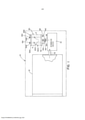
[0015] A Figura 1 é uma vista esquemática de um esterilizador mostrando uma câmara de esterilização conectada à uma bomba de vácuo tendo um conjunto de filtro montado no mesmo para remoção de névoa de óleo e odor em uma corrente a partir da bomba de vácuo.[0015] Figure 1 is a schematic view of a sterilizer showing a sterilization chamber connected to a vacuum pump having a filter assembly mounted thereon for removing oil mist and odor in a stream from the vacuum pump.
[0016] A Figura 2 é uma vista secional do conjunto de filtro mostrado na Figura 1 ilustrando uma configuração preferida da presente invenção.[0016] Figure 2 is a sectional view of the filter assembly shown in Figure 1 illustrating a preferred configuration of the present invention.
[0017] A Figura 3 é uma segunda vista secional do conjunto de filtro mostrado na Figura 1 tomada à 90° da seção mostrada na Figura 2.[0017] Figure 3 is a second sectional view of the filter assembly shown in Figure 1 taken at 90° from the section shown in Figure 2.
[0018] A Figura 4 é uma vista ampliada da extremidade inferior do conjunto de filtro mostrando como o óleo coletado pelo conjunto de filtro é retornado à uma parte superior do aparelho do conjunto de filtro; e[0018] Figure 4 is an enlarged view of the lower end of the filter assembly showing how the oil collected by the filter assembly is returned to an upper part of the filter assembly apparatus; and
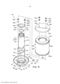
[0019] A Figura 5 é uma vista ampliada do conjunto de filtro.[0019] Figure 5 is an enlarged view of the filter set.
[0020] Tendo por referência agora os desenhos onde as amostras são somente para fins ilustrativos de uma configuração preferida da invenção e não para fins de limitação da mesma, a Figura 1 ilustra esquematicamente um esterilizador de baixa temperatura 10 (mostrado de forma ilusória) tendo uma câmara de esterilização 12 onde artigos (não mostrados) são esterilizados. A câmara de esterilização 12 está conectada à uma bomba de vácuo 14 que é operada para criar um vácuo dentro da câmara de esterilização 12 durante um ciclo de esterilização. Um duto de entrada 16 conecta a câmara de esterilização 12 à uma entrada da bomba de vácuo 14. Um duto de saída 18 conecta uma saída da bomba de vácuo 14 à um conjunto de filtro compacto 30 para remoção de névoa de óleo do ar evacuado da câmara de esterilização 12 durante um ciclo de esterilização.[0020] Referring now to the drawings where the samples are only for illustrative purposes of a preferred embodiment of the invention and not for the purposes of limiting the same, Figure 1 schematically illustrates a low temperature sterilizer 10 (illustratively shown) having a
[0021] A extremidade livre do duto de saída 18 inclui um flange se estendendo externamente 18a, mostrado nas Figuras 2 e 4. O conjunto de filtro 30 é basicamente compreendido por um filtro interno 200 para remoção de névoa de óleo de uma corrente de ar criada pela bomba de vácuo 14 e por um filtro externo 300 que circunda o filtro interno 200 para remoção de odores da corrente de ar criada pela bomba de vácuo 14. O filtro interno 200 e o filtro externo 300 são ambos sustentados em uma base 40.[0021] The free end of the
[0022] A base 40 é compreendida por uma porção em formato de taça 42, uma porção de armazenamento tubular 44 se estendendo da parte inferior da porção em forma de taça 42 e uma porção de flange 46 se estendendo externamente da borda superior da porção em formato de taça 42.[0022] The
[0023] A porção em formato de taça 42 da base 40 inclui uma parede inferior circular nivelada 52 e uma parede lateral cilíndrica 54 que se estende para cima a partir da periferia da parede inferior 52. A parede lateral 54 inclui uma seção 54a (melhor vista na Figura 2) onde a espessura da parede lateral 54 é ampliada.[0023] The cup-
[0024] A porção de armazenamento 44 se estende para baixo da parte inferior, isto é, do fundo da parede inferior 52. Na configuração mostrada, a porção de armazenamento tubular 44 é cilíndrica em seu formato e define uma abertura ou via cilíndrica 58 através da mesma. A parte inferior, extremidade livre da porção de armazenamento 44 inclui um pequeno flange se estendendo externamente 44a. O flange se estendendo externamente 44a da porção de armazenamento 44 está dimensionado para ser correspondente ao flange 18a no duto de saída 18 da bomba de vácuo 14. O flange 44a da porção de armazenamento 44 e o flange 18a do duto de saída 18 da bomba de vácuo 14 inclui cada um, uma ranhura circular, designadas 44b e 18b respectivamente, conforme melhor visto na Figura 4. As ranhuras circulares 18b, 44b estão dimensionadas para estarem alinhadas uma à outra e para receber um anel-O 62 entre as mesmas. Conforme mostrado nos desenhos, os flanges 44a, 18a na porção de armazenamento 44 da base 40 e o duto de saída 18 estão designados para serem correspondentes e se encaixarem um ao outro, onde o conjunto de filtro 30 possa ser anexado ao duto de saída 18 por meio de uma braçadeira circular 64 conforme é sabido convencionalmente. Conforme ilustrado nos desenhos, uma via 68 através do duto de saída 18 se comunica com a via 58 definida pela porção de armazenamento 44.[0024] The
[0025] A porção de flange 46 da base 40 se estende externamente ao longo da borda superior da porção em forma de taça 42 e inclui um colar ou aro 72 se estendendo para cima ao longo da borda externa do mesmo. A porção de flange 46 define uma superfície circular nivelada 46a dimensionada para receber o filtro externo 200, conforme ilustrado nos desenhos.[0025] The
[0026] Um ponto central ou eixo 82 está centralmente disposto dentro da porção em forma de taça 42. O eixo 82 está formado na superfície superior da parede inferior 52. O eixo 82 é geralmente cilíndrico no formato e inclui uma seção 84 de diâmetro reduzido na extremidade superior do mesmo. A seção de diâmetro reduzido 84 define uma área fragmentada ou espaçada 86 na extremidade superior do eixo 82. O eixo 82 tem uma superfície externa cilíndrica 82a e uma superfície interna cônica 82b. Um canal circular ou calha 92 está formado entre a superfície externa 82a do eixo 82 e a superfície interna 54b da parede lateral cilíndrica 54b. A superfície interna cônica 82b do eixo 82 define uma abertura cônica ou via 88 que se estende através da parede inferior 52 e se comunica com uma via cilíndrica 58 formada na porção de armazenamento tubular 44.[0026] A center point or
[0027] Um recesso ou cavidade 94 é formado na superfície externa 82a do eixo 82 próximo à parede inferior 52 da porção em formato de taça 42, conforme melhor visto na Figura 2.[0027] A recess or
[0028] Duas aberturas espaçadas 112, 114 são formadas através do eixo 82 para conectar o canal 92 à superfície cônica interna 82b do eixo 82. Na configuração mostrada, as aberturas 112, 114 se estendem geralmente de forma horizontal através do eixo 82, com a abertura 112 sendo disposta acima da abertura 114. A abertura superior 112 está dimensionada para receber um elemento válvula 120. A abertura inferior 114 está disposta para se comunicar com uma região inferior do canal 92.[0028] Two spaced
[0029] Na configuração mostrada, o elemento válvula 120 é uma válvula do tipo guarda-chuva formada por um polímero resiliente ou material elastomérico. O elemento válvula 120 tem uma porção circular 122 dimensionada para estar disposta dentro de uma via cônica 88 definida pela superfície cônica interna 82b do eixo 82 e para sobrepor ou cobrir a abertura 114, conforme melhor visto na Figura 4. O elemento válvula 120 inclui ainda uma porção de haste 124 que se estende a partir da porção circular 122 do elemento válvula 120. A porção de haste 124 inclui um colar ou área ampliada 126, conforme mostrado nos desenhos. Neste sentido, o eixo 82 e abertura 112 são dimensionados de modo que a porção de haste 124 possa se estender através da abertura 112 com a porção ampliada 126 da porção de haste 124 tocando a parede de extremidade definida pela cavidade 94.[0029] In the configuration shown, the
[0030] Em uma configuração preferida, o elemento válvula 120 é uma válvula do tipo guarda-chuva vendida sob Part No. UM18.0001-152 por Minivalve Inc. de Cleveland, Ohio.[0030] In a preferred configuration,
[0031] Conforme melhor visto na Figura 4, quando posicionada dentro da abertura 112, a porção circular 122 do elemento válvula 120 cobrirá a abertura 114, onde a abertura 114 se comunica com a via cônica 88 definida pela superfície interna 82b do eixo 82. Uma abertura rosqueada 132 está formada na seção espessa 54a da parede lateral 54 da porção em formato de taça 42 da base 40. A abertura rosqueada 132 está geralmente alinhada, isto é, em alinhamento com a cavidade 94 no eixo 82. A abertura rosqueada 132 está dimensionada para receber um plugue rosqueado convencional 134, conforme ilustrado na Figura 4.[0031] As best seen in Figure 4, when positioned within the
[0032] Dois suportes ou blocos espaçados 142, 144 são formados dentro da porção em formato de taça 42, conforme melhor visto na Figura 3. Os blocos ou suportes 142, 144 se estendem a partir da superfície interna 52a da parede inferior 52 e a partir da superfície interna 54b da parede lateral 54. Os blocos 142, 144 estão dispostos em laterais opostas do eixo 82. Os orifícios rosqueados são formados nos blocos 142, 144 para receber hastes rosqueadas alongadas 152, 154 que se estendem para cima da base 40, conforme mostrado nos desenhos. As extremidades das hastes 142, 144 são rosqueadas, conforme será explicado em maiores detalhes abaixo.[0032] Two spaced supports or blocks 142, 144 are formed within the cup-shaped
[0033] O filtro interno 200 é um membro tubular alongado. Na configuração mostrada, o filtro interno 200 é cilíndrico em formato e é compreendido por um membro filtro tubular 212 e anéis ou colares circulares 214 nas extremidades do membro filtro tubular 212. Uma lateral de cada colar 214 define uma ranhura circular dimensionada para receber uma extremidade do membro filtro tubular 212. A outra lateral do colar 214 tem um formato de uma parede cilíndrica 216. A parede 216 do colar 214 está dimensionada para receber a seção de diâmetro reduzido 84 do eixo 82. A porção de parede 216 do colar 214 inclui uma borda de recesso dimensionada para receber um anel O 218 que sela o colar 214 do filtro interno 200 contra o eixo 82, conforme melhor visto na Figura 3. O filtro interno 200 tem uma primeira extremidade 200A e uma segunda extremidade 200B. A primeira extremidade 200A está conectada ao eixo 82 da base 40 com a segunda extremidade 200B posicionada acima. Uma capa 232 está dimensionada para ser colocada em cima da segunda extremidade 200B do filtro interno 200. A capa 232 inclui uma porção cilíndrica localizada centralmente 234 dimensionada para ser recebida dentro da parede 216 do colar 214 na segunda extremidade 200B do filtro interno 200. O anel O 236 está disposto entre a porção cilíndrica 234 da capa 323 e a parede 216 do colar 214 no filtro interno 200. A capa 232 inclui abas que se estendem externamente 242, 244 em laterais opostas da capa 232. Uma abertura 246 é formada em cada aba 242, 244. As aberturas 246 estão dimensionadas e posicionadas para receber as extremidades rosqueadas das hastes alongadas 152, 154 entre as mesmas. Elementos de fixação serrilhados 252 são rosqueados nas extremidades das hastes alongadas 152, 154 com arruelas 254 para fixar a capa 232 na segunda extremidade 200B do filtro interno 200 e para comprimir e fixar o filtro interno 200 na base 40.[0033] The
[0034] O filtro externo 300 é dimensionado para ser disposto em cima da porção de flange 46 da base 40. Conforme ilustrado nos desenhos, o filtro externo 300 é espaçado do filtro interno 200 para definir uma câmera circular 310 entre o filtro interno 200 e o filtro externo 300. Na configuração mostrada, o filtro externo 300 é cilíndrico em formato e inclui um elemento filtro 322. Capas de extremidade 324 estão providas em cada extremidade do elemento filtro 322. Uma extremidade 300A do filtro externo 300 está dimensionada para permanecer em cima da superfície circular voltada para cima 46a da porção de flange 46 da base 40. Uma cobertura 332 que é circular em formato, está dimensionada para ser colocada sobre a segunda extremidade 300B do filtro externo 300. A cobertura 332 inclui uma parede ou aba se estendendo para baixo 334 para capturar a extremidade do filtro externo 300. A cobertura 332 ainda inclui aberturas espaçadas 336 dimensionadas e dispostas para receber as extremidades das hastes rosqueadas 152, 154 entre as mesmas. Os fixadores serrilhados 342 são rosqueados nas extremidades das hastes rosqueadas 152, 154 para fixar a cobertura 332 no filtro externo 300 fixando assim o filtro externo 300 na base 40. As vedações 344 estão dispostas entre os fixadores 342 e cobertura 332 para formar uma vedação entre os mesmos.[0034] The
[0035] Conforme mostrado nos desenhos, o filtro interno 200 define uma câmara interna cilíndrica 260 que se comunica com a via cônica 88 através do eixo 82, com a via cilíndrica 58 através da porção de armazenamento 44 da base 40, e abertura cilíndrica 68 ao duto de saída 18 da bomba de vácuo 14.[0035] As shown in the drawings, the
[0036] Em uma configuração preferida, o filtro interno 200 é compreendido por um filtro vendido sob o catálogo No. 112453 por Alcatel Vacuum Products Inc. de Hingham, Massachusetts.[0036] In a preferred configuration, the
[0037] O filtro externo 300 é geralmente compreendido por um carbono ativado para remover odores do ar ao passar pelo mesmo. Em uma configuração preferida, o filtro interno 300 é um filtro vendido sob Part. No. 3167-EL-02-SD 18483 por Solberg Manufacturing Inc. de Itasca, Illinois.[0037] The
[0038] Tendo por referência agora a operação do conjunto de filtro 30, conforme melhor visto na Figura 4, o conjunto de filtro 30 está anexado ao duto de saída 18 da bomba de vácuo 14 por meio de uma braçadeira circular 64. Neste sentido, o conjunto de filtro 30 está disposto em uma direção geralmente vertical onde os eixos dos filtros interno e externo 200, 300 são geralmente verticais. Durante a operação da bomba de vácuo 14, uma corrente de ar, sob pressão, isto é, a saída da bomba de vácuo 14 flui dentro da câmara interna 260 do filtro interno 200. O óleo e outro material dentro da corrente de ar que são bombeados da câmara de esterilização, são filtrados pelo filtro interno 200 e a maior parte confinada dentro da câmara interna 260 definida pelo filtro interno 200. O ar filtrado ao passar através do filtro interno 200, entra na câmara circular 310 definida entre o filtro interno 200 e o filtro externo 300. O óleo separado pelo filtro interno 200 permanece dentro da câmara interna 260 conforme ilustrado por gotas “D” na Figura 4. Neste sentido, a maior parte da névoa de óleo dentro da corrente de ar criada pela bomba de vácuo 14 será retida dentro da câmara interna 260 do conjunto de filtro 30. Conforme ilustrado na Figura 4, uma porção de óleo pode penetrar através do filtro interno 200 e ser coletado na superfície externa do filtro interno 200. As gotas de óleo “D” que seriam tipicamente coletadas ao longo da superfície externa do filtro interno 200, fluem pela gravidade ao canal circular 92 formado na base 40, conforme ilustrado na Figura 4.[0038] With reference now to the operation of the
[0039] O ar filtrado pelo filtro interno 200 seria forçado para dentro da câmara circular externa 310 ao filtro externo 300. Conforme abaixo indicado, o filtro externo 300 é preferencialmente formado por um material carvão ou outro material similar que removeria odores da corrente de ar. O ar filtrado seria então liberado ao ambiente circundante após ter sido filtrado pelo filtro interno 200 e pelo filtro externo 300.[0039] The air filtered by the
[0040] Durante a operação da bomba de vácuo 14 existe pressão dentro da câmara interna 260 definida pelo filtro interno 200 e pela câmara circular externa 310 definida pelo filtro externo 300. Conforme será apreciado, a pressão dentro do filtro interno 200 será maior do que a pressão na câmara circular externa 310. Como um resultado, a pressão dentro da câmara interna 260 manterá a porção circular 122 do elemento válvula 120 pressionada contra a superfície interna 82b do eixo 82, dessa forma cobrindo e vedando a abertura 114 formada através da parede lateral do eixo 82. Isso garante que a corrente de ar criada pela bomba de vácuo 14 flua através de meios filtrantes do filtro interno 200 antes de alcançar a câmara circular externa 310 do conjunto de filtro 30.[0040] During operation of the
[0041] O óleo filtrado da corrente de ar pelo filtro interno 200 fluirá ao longo da superfície interna do filtro interno 200 para baixo na via em formato de funil 88 na base 40 e será retornado à bomba de vácuo 14 através da via 58 no duto de saída 18. Como será apreciado, a maior parte da névoa de óleo na corrente de ar será filtrada pelo filtro interno 200. Entretanto, conforme acima indicado, uma porção de óleo será forçada, isto é, penetrada dentro do filtro interno 200 e gotas “D” serão formadas ao longo da superfície externa do filtro interno 200 na câmara circular 310. As gotas de óleo “D” serão drenadas e formarão uma piscina “P” de óleo no canal circular 92, conforme ilustrado na Figura 4.[0041] Oil filtered from the air stream by the
[0042] Durante os períodos em que a bomba de vácuo 14 não estiver operando será permitido que qualquer óleo coletado dentro do canal circular 92 na base 40 flua de volta à via 88 da base 40 por meio da gravidade quando a pressão do óleo no canal circular 92 for maior do que a pressão na via 88. Em outras palavras, será permitido que o óleo coletado na câmara circular 310 seja drenado de volta à bomba de vácuo 14 através da câmara interna 260 quando a pressão na câmara circular 310 exceder a pressão na câmara interna 260.[0042] During periods when the
[0043] A presente invenção provê assim um conjunto de filtro compacto para remoção de névoa de óleo e odor a partir de uma bomba de vácuo. A presente invenção provê ainda um conjunto de filtro de fácil limpeza e manutenção.[0043] The present invention thus provides a compact filter assembly for removing oil mist and odor from a vacuum pump. The present invention further provides a filter assembly that is easy to clean and maintain.
[0044] A descrição acima exposta é uma configuração específica da presente invenção. Será apreciado que essa configuração seja descrita somente para fins ilustrativos e que alterações numerosas e modificações possam ser praticadas pelos especialistas no estado da técnica sem deixar o alcance e o escopo da invenção. Será compreendido que todas as referidas modificações e alterações sejam incluídas enquanto as mesmas surjam dentro do escopo da invenção conforme reivindicações e equivalentes da mesma.[0044] The above description is a specific embodiment of the present invention. It will be appreciated that this configuration is described for illustrative purposes only and that numerous alterations and modifications may be practiced by those skilled in the art without departing from the scope and scope of the invention. It will be understood that all said modifications and changes are included as they come within the scope of the invention as per claims and equivalents thereof.
Claims (9)
Applications Claiming Priority (3)
| Application Number | Priority Date | Filing Date | Title |
|---|---|---|---|
| US14/014,874 | 2013-08-30 | ||
| US14/014,874 US9120042B2 (en) | 2013-08-30 | 2013-08-30 | Compact filter assembly for removing oil mist and odor from an airstream |
| PCT/US2014/045546 WO2015030935A1 (en) | 2013-08-30 | 2014-07-07 | Compact filter assembly for removing oil mist and odor from an airstream |
Publications (2)
| Publication Number | Publication Date |
|---|---|
| BR112016004034A2 BR112016004034A2 (en) | 2017-08-01 |
| BR112016004034B1 true BR112016004034B1 (en) | 2022-01-25 |
Family
ID=52581228
Family Applications (1)
| Application Number | Title | Priority Date | Filing Date |
|---|---|---|---|
| BR112016004034-1A BR112016004034B1 (en) | 2013-08-30 | 2014-07-07 | APPLIANCE FOR REMOVING OIL MIST AND ODORS FROM AN AIR CURRENT |
Country Status (10)
| Country | Link |
|---|---|
| US (1) | US9120042B2 (en) |
| EP (1) | EP3038734B1 (en) |
| JP (1) | JP6049952B2 (en) |
| CN (1) | CN105592908B (en) |
| AU (1) | AU2014311816B2 (en) |
| BR (1) | BR112016004034B1 (en) |
| CA (1) | CA2920635C (en) |
| ES (1) | ES2706773T3 (en) |
| MX (1) | MX2016002048A (en) |
| WO (1) | WO2015030935A1 (en) |
Families Citing this family (5)
| Publication number | Priority date | Publication date | Assignee | Title |
|---|---|---|---|---|
| US9908070B2 (en) * | 2015-11-23 | 2018-03-06 | Pall Corporation | Fuel tank inerting prefilter assemblies, devices, and methods of use |
| DE102016009487A1 (en) * | 2016-08-05 | 2018-02-08 | Mann + Hummel Gmbh | Separating element, device and method for the separation of liquid from raw gas or raw gas mixture of an engine / compressor |
| GB2592573A (en) * | 2019-12-19 | 2021-09-08 | Leybold France S A S | Lubricant-sealed vacuum pump, lubricant filter and method. |
| CN111359290A (en) * | 2020-03-30 | 2020-07-03 | 成都谦睿哲环保科技有限公司 | Filter cartridge device with multilayer filter screen |
| EP4342562A1 (en) * | 2022-09-20 | 2024-03-27 | MANN+HUMMEL GmbH | Gas filter system |
Family Cites Families (44)
| Publication number | Priority date | Publication date | Assignee | Title |
|---|---|---|---|---|
| US456464A (en) * | 1891-07-21 | Combined steam-condenser | ||
| US1714825A (en) * | 1927-03-14 | 1929-05-28 | William H Gast | Oil-water and air separator |
| US2521785A (en) * | 1948-04-09 | 1950-09-12 | Metal Textile Corp | Separator for removing entrained liquid particles from a flowing gaseous medium |
| US2863563A (en) * | 1953-06-26 | 1958-12-09 | Sintercast Corp America | Filter |
| US2710666A (en) * | 1953-07-27 | 1955-06-14 | H2Oil Engineering Corp | Gas line safety shut off device |
| SE345813B (en) * | 1969-12-01 | 1972-06-12 | Munters C | |
| US3708965A (en) * | 1970-09-08 | 1973-01-09 | K Domnick | Gas filters |
| US3772857A (en) * | 1971-08-23 | 1973-11-20 | Gits Bros Mfg Co | Water air separator |
| JPS5392973A (en) * | 1977-01-26 | 1978-08-15 | Sanetsu Kk | Oil mist remover |
| DE7726666U1 (en) * | 1977-08-27 | 1978-05-18 | Filterwerk Mann & Hummel Gmbh, 7140 Ludwigsburg | OIL SEPARATOR FOR AIR |
| US4231768A (en) * | 1978-09-29 | 1980-11-04 | Pall Corporation | Air purification system and process |
| CA1122906A (en) * | 1979-04-06 | 1982-05-04 | James P. Donachiue | Air prefilter |
| DE2931702A1 (en) * | 1979-08-04 | 1981-02-19 | Kernforschungsz Karlsruhe | DROP SEPARATOR FOR THE SEPARATION OF LIQUID DROPS FROM GAS OR STEAM FLOWS |
| US4500332A (en) * | 1982-09-30 | 1985-02-19 | Donaldson Company, Inc. | Throughput blade for louvered separators |
| DE3811441A1 (en) * | 1988-04-06 | 1989-10-26 | Karl Poetz | SEPARATOR ELEMENT |
| US5141714A (en) * | 1989-08-01 | 1992-08-25 | Kabushiki Kaisha Riken | Exhaust gas cleaner |
| US5190569A (en) * | 1991-06-13 | 1993-03-02 | Mcgrath Wayne D | Purification apparatus for pneumatic systems |
| JPH0634722U (en) * | 1992-10-21 | 1994-05-10 | 和興産業株式会社 | Separation device |
| JP2556657B2 (en) * | 1993-12-02 | 1996-11-20 | 宏行 ▲角▼野 | air purifier |
| US5702602A (en) * | 1995-12-20 | 1997-12-30 | Baldwin Filters, Inc. | Filter system with environmentally friendly filter cartridge |
| US5738785A (en) * | 1995-12-20 | 1998-04-14 | Baldwin Filters, Inc. | Oil filter housing |
| US5753117A (en) * | 1996-06-05 | 1998-05-19 | Fleetguard, Inc. | Replaceable filter element and snap-on filter lid assembly |
| JPH1043533A (en) * | 1996-08-08 | 1998-02-17 | Toshiba Fa Syst Eng Kk | Air filter device |
| DE29700579U1 (en) | 1997-01-15 | 1997-03-13 | Mann & Hummel Filter | Arrangement for separating liquid particles from a gas stream |
| JP2001120932A (en) * | 1999-10-21 | 2001-05-08 | Nippon Rokaki Kk | Filter unit and filter device |
| US20020083691A1 (en) * | 2000-12-28 | 2002-07-04 | Li-Lin Chang | Oil filter device of smoke exhaust |
| WO2004052499A1 (en) * | 2002-04-18 | 2004-06-24 | Hal Alper | Method for filtering pernicious non-gaseous contaminants from airand benign gases |
| GB2389322B (en) * | 2002-06-07 | 2005-08-17 | Baldwin Filters Inc | Environmentally friendly dual lube venturi filter cartridge |
| US7614390B2 (en) * | 2007-08-23 | 2009-11-10 | Cummins Filtration Ip Inc. | Two stage drainage gas-liquid separator |
| US20060143853A1 (en) * | 2004-12-30 | 2006-07-06 | Agerlid Charles G | Liquid separator for vacuum filter |
| US7563299B2 (en) * | 2005-11-08 | 2009-07-21 | Illinois Tool Works Inc. | Filtering apparatus, filter regulator for use with spray gun and spraying system using the same |
| BRPI0604518A (en) * | 2005-11-08 | 2007-08-28 | Devilbiss Equipamentos Para Pi | regulating filter |
| US20070209983A1 (en) | 2006-03-13 | 2007-09-13 | Deere & Company, A Delaware Corporation | Hydraulic lubrication filter assembly |
| US20090019823A1 (en) * | 2007-06-20 | 2009-01-22 | William Michael Juliar | Auxiliary Power Unit Exhaust Filter |
| US7909921B1 (en) * | 2007-11-15 | 2011-03-22 | Gilbert John R | Pollution control device |
| DE102007062098A1 (en) * | 2007-12-21 | 2009-06-25 | Mahle International Gmbh | Oil Mist Separators |
| CN102196848B (en) * | 2008-10-27 | 2014-07-09 | 康明斯过滤Ip公司 | Filter cartridge having a filter within a filter, and an endplate sealing structure on an outer filter element |
| EP2236185B1 (en) * | 2009-04-03 | 2012-01-04 | Delphi Technologies Holding S.à.r.l. | Filter Assembly |
| JP2010247135A (en) | 2009-04-15 | 2010-11-04 | Takami Onuma | Method for removing oil mist, bad odor or the like, and removing filter |
| DE102009031420B4 (en) * | 2009-07-02 | 2021-01-28 | Leybold Gmbh | Multi-stage oil separator |
| US8801825B2 (en) | 2010-11-22 | 2014-08-12 | Florida Power & Light Company | Systems and methods for air intake filter assemblies |
| CN103717286A (en) * | 2011-07-29 | 2014-04-09 | 唐纳森公司 | Gas/liquid separator assemblies and components |
| CN103987928B (en) * | 2011-10-20 | 2017-07-21 | 唐纳森公司 | Air/oil separators component, part and method |
| US20140033926A1 (en) * | 2012-08-03 | 2014-02-06 | Robert Scott Fassel | Filtration System |
-
2013
- 2013-08-30 US US14/014,874 patent/US9120042B2/en active Active
-
2014
- 2014-07-07 CN CN201480046716.3A patent/CN105592908B/en active Active
- 2014-07-07 BR BR112016004034-1A patent/BR112016004034B1/en active IP Right Grant
- 2014-07-07 MX MX2016002048A patent/MX2016002048A/en unknown
- 2014-07-07 WO PCT/US2014/045546 patent/WO2015030935A1/en active Application Filing
- 2014-07-07 EP EP14839397.8A patent/EP3038734B1/en active Active
- 2014-07-07 AU AU2014311816A patent/AU2014311816B2/en active Active
- 2014-07-07 ES ES14839397T patent/ES2706773T3/en active Active
- 2014-07-07 CA CA2920635A patent/CA2920635C/en active Active
- 2014-07-07 JP JP2016534700A patent/JP6049952B2/en active Active
Also Published As
| Publication number | Publication date |
|---|---|
| AU2014311816B2 (en) | 2016-03-24 |
| CA2920635A1 (en) | 2015-03-05 |
| CN105592908A (en) | 2016-05-18 |
| CN105592908B (en) | 2018-05-11 |
| EP3038734A1 (en) | 2016-07-06 |
| WO2015030935A1 (en) | 2015-03-05 |
| EP3038734A4 (en) | 2017-06-21 |
| MX2016002048A (en) | 2016-06-17 |
| BR112016004034A2 (en) | 2017-08-01 |
| CA2920635C (en) | 2016-06-28 |
| EP3038734B1 (en) | 2018-11-21 |
| US20150059300A1 (en) | 2015-03-05 |
| JP2016529102A (en) | 2016-09-23 |
| US9120042B2 (en) | 2015-09-01 |
| ES2706773T3 (en) | 2019-04-01 |
| JP6049952B2 (en) | 2016-12-21 |
Similar Documents
| Publication | Publication Date | Title |
|---|---|---|
| BR112016004034B1 (en) | APPLIANCE FOR REMOVING OIL MIST AND ODORS FROM AN AIR CURRENT | |
| JP7033331B2 (en) | Surgical collection system | |
| IL257137A (en) | Blood sample optimization system and blood contaminant sequestration device and method | |
| US8465439B2 (en) | Tissue collection and separation device | |
| ES2377776T3 (en) | Procedure and apparatus for drying objects in washing device | |
| ES2684068B2 (en) | CONTAINER FOR MENSTRUAL RETENTION AND EMPTYING | |
| WO2018085953A1 (en) | Device for extracting volatile oils contained in organic raw material by means of steam distillation and internal distillation method | |
| ES2828304T3 (en) | Filtration facility | |
| BR112019021203A2 (en) | filter system with filter element and secondary element for closing a central tube | |
| CN209347240U (en) | A kind of sharp instrument storage box with cutter device | |
| KR101966903B1 (en) | An air circulator | |
| ES2396459T3 (en) | Sterile container | |
| US20190160410A1 (en) | Filter medium compression system for smoke evacuation | |
| US20140283925A1 (en) | Fluids collection and drain system | |
| WO2014197872A1 (en) | Heating element for reducing foaming during saliva collection | |
| US20150107603A1 (en) | Reservoir antechamber for reducing foaming during saliva collection | |
| KR101767426B1 (en) | Wall afforestation flower pot assembly for improved indoor environment using rhizosphere of plants | |
| JP6367695B2 (en) | Air cleaner | |
| CN203075351U (en) | Filter for secondary filtering of infusion apparatus and infusion apparatus | |
| CN204193195U (en) | A kind of lower liquid aerofluxus, filtration, only liquid and blood return preventing infusion device automatically | |
| JP3193930U (en) | Oil water separator | |
| CN220174235U (en) | Pest trapping device | |
| CN205357914U (en) | Prevent volatile electrothermal vaporizing device | |
| CN208898840U (en) | Cordate houttuynia essential oil extraction equipment | |
| KR100966046B1 (en) | The dehumidifier used compressor |
Legal Events
| Date | Code | Title | Description |
|---|---|---|---|
| B06U | Preliminary requirement: requests with searches performed by other patent offices: procedure suspended [chapter 6.21 patent gazette] | ||
| B09A | Decision: intention to grant [chapter 9.1 patent gazette] | ||
| B16A | Patent or certificate of addition of invention granted [chapter 16.1 patent gazette] |
Free format text: PRAZO DE VALIDADE: 20 (VINTE) ANOS CONTADOS A PARTIR DE 07/07/2014, OBSERVADAS AS CONDICOES LEGAIS. |