JP6048868B2 - RF coil for measuring nuclear magnetic resonance phenomena - Google Patents
RF coil for measuring nuclear magnetic resonance phenomena Download PDFInfo
- Publication number
- JP6048868B2 JP6048868B2 JP2012148036A JP2012148036A JP6048868B2 JP 6048868 B2 JP6048868 B2 JP 6048868B2 JP 2012148036 A JP2012148036 A JP 2012148036A JP 2012148036 A JP2012148036 A JP 2012148036A JP 6048868 B2 JP6048868 B2 JP 6048868B2
- Authority
- JP
- Japan
- Prior art keywords
- coil
- vertical band
- guard ring
- wing
- portions
- Prior art date
- Legal status (The legal status is an assumption and is not a legal conclusion. Google has not performed a legal analysis and makes no representation as to the accuracy of the status listed.)
- Active
Links
Images


Classifications
-
- G—PHYSICS
- G01—MEASURING; TESTING
- G01R—MEASURING ELECTRIC VARIABLES; MEASURING MAGNETIC VARIABLES
- G01R33/00—Arrangements or instruments for measuring magnetic variables
- G01R33/20—Arrangements or instruments for measuring magnetic variables involving magnetic resonance
- G01R33/28—Details of apparatus provided for in groups G01R33/44 - G01R33/64
- G01R33/32—Excitation or detection systems, e.g. using radio frequency signals
- G01R33/34—Constructional details, e.g. resonators, specially adapted to MR
- G01R33/34092—RF coils specially adapted for NMR spectrometers
-
- G—PHYSICS
- G01—MEASURING; TESTING
- G01R—MEASURING ELECTRIC VARIABLES; MEASURING MAGNETIC VARIABLES
- G01R33/00—Arrangements or instruments for measuring magnetic variables
- G01R33/20—Arrangements or instruments for measuring magnetic variables involving magnetic resonance
- G01R33/28—Details of apparatus provided for in groups G01R33/44 - G01R33/64
- G01R33/32—Excitation or detection systems, e.g. using radio frequency signals
- G01R33/34—Constructional details, e.g. resonators, specially adapted to MR
- G01R33/343—Constructional details, e.g. resonators, specially adapted to MR of slotted-tube or loop-gap type
-
- G—PHYSICS
- G01—MEASURING; TESTING
- G01R—MEASURING ELECTRIC VARIABLES; MEASURING MAGNETIC VARIABLES
- G01R33/00—Arrangements or instruments for measuring magnetic variables
- G01R33/20—Arrangements or instruments for measuring magnetic variables involving magnetic resonance
- G01R33/28—Details of apparatus provided for in groups G01R33/44 - G01R33/64
- G01R33/32—Excitation or detection systems, e.g. using radio frequency signals
- G01R33/34—Constructional details, e.g. resonators, specially adapted to MR
- G01R33/34007—Manufacture of RF coils, e.g. using printed circuit board technology; additional hardware for providing mechanical support to the RF coil assembly or to part thereof, e.g. a support for moving the coil assembly relative to the remainder of the MR system
Landscapes
- Physics & Mathematics (AREA)
- Condensed Matter Physics & Semiconductors (AREA)
- General Physics & Mathematics (AREA)
- Magnetic Resonance Imaging Apparatus (AREA)
Description
本発明は、核磁気共鳴現象を励起または検出するためのRFコイルに関する。 The present invention relates to an RF coil for exciting or detecting a nuclear magnetic resonance phenomenon.
核磁気共鳴現象(NMR: Nuclear Magnetic Resonance)を利用した装置として、NMR装置やMRI(Magnetic Resonance Imaging)装置が実用化されている。磁場中におかれた原子核はゼーマン分裂を起こして、複数のエネルギー準位に分かれる。これらの準位のエネルギー差に相当するエネルギー(周波数によって決定される)を電磁波によって与えることで、エネルギーの吸収と放出が発生する。この現象が核磁気共鳴現象である。NMR装置やMRI装置は、物理学、化学の分野に限られず、生物学、医学、薬学、農学、食品科学、材料科学、化学工業などの様々な分野で幅広く利用されている。例えば、有機化学などにおける構造決定や同定、タンパク質などの立体構造解析や分子間相互作用解析、医療用MRIなどである。 An NMR apparatus and an MRI (Magnetic Resonance Imaging) apparatus have been put to practical use as apparatuses utilizing the nuclear magnetic resonance phenomenon (NMR). A nucleus placed in a magnetic field undergoes Zeeman splitting and splits into multiple energy levels. By applying energy corresponding to the energy difference between these levels (determined by the frequency) by electromagnetic waves, energy absorption and emission occur. This phenomenon is a nuclear magnetic resonance phenomenon. The NMR apparatus and the MRI apparatus are not limited to the fields of physics and chemistry, but are widely used in various fields such as biology, medicine, pharmacy, agriculture, food science, material science, and chemical industry. For example, structure determination and identification in organic chemistry, three-dimensional structure analysis of proteins, intermolecular interaction analysis, medical MRI, and the like.
これらの装置は、同一同位体種の原子核でも試料中での各原子周囲の磁気的環境によって生じるわずかな周波数変化や核磁気共鳴の緩和現象を測定することができる。これにより、化学シフト、信号強度(定量)、緩和時間、スピン結合、NOE(Nuclear Overhauser Effect: 核オーバーハウザー効果)などの情報を得ることができる。これらの情報か
ら分子構造、分子間相互作用、運動性などを求めることが可能である。このように、非侵襲的に原子レベルの測定が可能であるという利点がある。一方、測定信号が弱い(感度が悪い)という問題がある。これは、ゼーマン分裂によるエネルギー差は非常に小さく、それぞれのエネルギー準位の占有数はボルツマン分布に依存するためである。
These devices can measure slight frequency changes and nuclear magnetic resonance relaxation phenomena caused by the magnetic environment around each atom in the sample even in nuclei of the same isotope species. Thereby, information such as chemical shift, signal intensity (quantitative), relaxation time, spin coupling, and NOE (Nuclear Overhauser Effect) can be obtained. From this information, it is possible to obtain molecular structure, intermolecular interaction, mobility, and the like. Thus, there is an advantage that atomic level measurement is possible non-invasively. On the other hand, there is a problem that the measurement signal is weak (poor sensitivity). This is because the energy difference due to Zeeman splitting is very small, and the number of occupied energy levels depends on the Boltzmann distribution.
信号強度は、磁場強度の3/2乗に比例するため、NMR装置やMRI装置において磁場強度を向上させる開発が行われてきた。現在は、残余磁気双極子間相互作用の観測や、TROSY効果、四極子核の観測などでは23.5T(1Hの共鳴周波数で1GHz)以
上の強磁場が必要とされている。そのため、今後も超電導磁石の開発による磁場強度の向上が続けられていくと予想できる。
Since the signal strength is proportional to the 3/2 power of the magnetic field strength, development for improving the magnetic field strength in the NMR apparatus and the MRI apparatus has been performed. At present, a strong magnetic field of 23.5 T ( 1 GHz at 1 H resonance frequency) or more is required for the observation of the interaction between the residual magnetic dipoles, the TROSY effect, and the observation of the quadrupole nucleus. Therefore, it can be expected that the magnetic field strength will continue to be improved by developing superconducting magnets.
核磁気共鳴現象を発生させるには、超電導磁石などによる静磁場と直交する向きに核磁気共鳴周波数の信号を送受信するアンテナ(RFコイル)が必要となる。パワーアンプから高周波信号をこのRFコイルに送信し測定試料に高周波磁場(B1磁場)を照射するこ
とで励起状態を作り出し、測定試料から発生するNMR信号をRFコイルによって受信する。
In order to generate a nuclear magnetic resonance phenomenon, an antenna (RF coil) that transmits and receives a signal of a nuclear magnetic resonance frequency in a direction orthogonal to a static magnetic field by a superconducting magnet or the like is required. A high frequency signal is transmitted from the power amplifier to the RF coil, and the measurement sample is irradiated with a high frequency magnetic field (B 1 magnetic field) to create an excited state, and an NMR signal generated from the measurement sample is received by the RF coil.
NMR装置やMRI装置に用いられる従来のRFコイルとして、図19に示すような形状のRFコイルが知られている。図19(A)は非特許文献1などで紹介されており、Alderman−Grant型と称される。図19(B)は、非特許文献2などで紹介されており、鞍型と称される。これらのRFコイルは巻き数1ターンのコイルである。RFコイルの巻き数を増やすと自己共振周波数が低くなってしまい、高い周波数ではRFコイルとして利用できないためである。
As a conventional RF coil used for an NMR apparatus or an MRI apparatus, an RF coil having a shape as shown in FIG. 19 is known. FIG. 19A is introduced in Non-Patent
自己共振周波数(Self Resonance Frequency)とは、コイルがコイルとして振る舞える最大の周波数である。コイルには望まなくても浮遊キャパシタンスが存在し、これとの間で並列共振を起きるため自己共振が生じる。自己共振周波数よりも高い周波数では、コイルはコイルとして機能せずコンデンサとして機能してしまう。 The self-resonance frequency is the maximum frequency at which a coil can behave as a coil. The coil has a stray capacitance even if not desired, and a self-resonance occurs due to a parallel resonance with the coil. At a frequency higher than the self-resonance frequency, the coil does not function as a coil but functions as a capacitor.
900MHz程度のNMR装置では、図19に示した形状のRFコイルが用いられているが、このRFコイルの自己共振周波数は900MHzから1GHz程度である。核磁気共鳴周波数が1GHz(静磁場強度で23.5T)を超える場合には、900MHz用のRFコイルをそのまま利用することができない。したがって、RFコイルの自己共振周波数を従来よりも高くする必要がある。 In an NMR apparatus of about 900 MHz, an RF coil having the shape shown in FIG. 19 is used. The self-resonant frequency of this RF coil is about 900 MHz to 1 GHz. When the nuclear magnetic resonance frequency exceeds 1 GHz (23.5 T in static magnetic field strength), the 900 MHz RF coil cannot be used as it is. Therefore, the self-resonant frequency of the RF coil needs to be higher than before.
なお、RFコイルの自己共振周波数の高周波化は、1GHz超のNMR装置のみに要請されるわけではない。RFコイルの自己共振周波数は、RFコイルの大きさやその他の要因によっても規定される。したがって、1GHzよりも低い共鳴周波数を用いるNMR装置やMRI装置においても、磁場強度の向上により核磁気共鳴周波数が高くなれば、いずれ自己共振周波数の限界に到達してしまう。 In addition, the high frequency of the self-resonant frequency of the RF coil is not required only for an NMR apparatus exceeding 1 GHz. The self-resonant frequency of the RF coil is also defined by the size of the RF coil and other factors. Therefore, even in an NMR apparatus or an MRI apparatus that uses a resonance frequency lower than 1 GHz, the limit of the self-resonance frequency will eventually be reached if the nuclear magnetic resonance frequency increases due to the improvement of the magnetic field strength.
自己共振周波数の向上させるための最も簡単な方法は、RFコイルや測定試料の直径を小さくすることである。しかしこの方法では、測定感度の低下につながるため好ましくない。また、他の方法として垂直バンド部とガードリングの距離を離すという手法もあるが、キャパシタンス成分の低下により自己共振周波数は向上するものの、測定試料空間の直径は変化せずコイルの直径が大きくなり、これによりコイルと測定試料の距離が離れてしまう。また、高周波磁場が照射されてしまう測定試料が存在しない空間も大きくなりRFコイルの効率が低下し、コイルの性能が低下してしまう。 The simplest method for improving the self-resonant frequency is to reduce the diameter of the RF coil or the measurement sample. However, this method is not preferable because it leads to a decrease in measurement sensitivity. Another method is to increase the distance between the vertical band part and the guard ring, but the self-resonance frequency is improved by lowering the capacitance component, but the diameter of the measurement sample space does not change and the coil diameter increases. As a result, the distance between the coil and the measurement sample is increased. In addition, the space where there is no measurement sample that is irradiated with the high-frequency magnetic field is increased, and the efficiency of the RF coil is lowered, and the performance of the coil is lowered.
このような課題を考慮し、本発明の目的は、測定感度の低下を招くことなく、従来よりも高い自己共振周波数を有する核磁気共鳴現象測定用のRFコイルを提供することにある。 In consideration of such problems, an object of the present invention is to provide an RF coil for measuring a nuclear magnetic resonance phenomenon having a higher self-resonance frequency than before without causing a decrease in measurement sensitivity.
本発明にかかるRFコイルは、核磁気共鳴現象を励起または検出するためのRFコイルであって、
外形がほぼ円筒形または楕円筒形または多角筒形をしており、前記円筒または楕円筒または多角筒の軸方向に離間して設けられた2つのガードリングと、
前記軸方向に延びるほぼ直線形状の第1および第2の垂直バンド部であって、互いに対向して設けられた第1および第2の垂直バンド部と、
を備え、
各ガードリング位置において、
(1)前記第1および第2の垂直バンド部の両方が、ほぼ直線形状またはテーパ形状(順テーパと逆テーパを含む)のストレート型、または、
(2)前記第1および第2の垂直バンド部の両方が、ほぼ直線形状またはテーパ形状のストレート型であり、かつ、ガードリングの周面に対向する位置であり前記第1および第2の垂直バンドの間に、これらの垂直バンド部と分離して分離ウィング部が設けられた分離ウィング型、または、
(3)前記第1および第2の垂直バンド部の一方は、ほぼ直線形状またはテーパ形状であり、他方の垂直バンド部は、ガードリングに沿って前記一方の垂直バンド部に突出するウィング部を有する非対称ウィング型、または、
(4)前記第1および第2の垂直バンド部が、ガードリングの周面に対向して設けられた接続部によって接続されている接続型、
のいずれかの構造をとる。
An RF coil according to the present invention is an RF coil for exciting or detecting a nuclear magnetic resonance phenomenon,
Two guard rings having an outer shape that is substantially cylindrical, elliptical, or polygonal, and spaced apart in the axial direction of the cylinder, elliptical, or polygonal;
First and second vertical band portions having substantially linear shapes extending in the axial direction, the first and second vertical band portions provided facing each other;
With
At each guard ring position
(1) Both of the first and second vertical band portions are straight types having a substantially linear shape or a tapered shape (including a forward taper and a reverse taper), or
(2) Both of the first and second vertical band portions are straight types having a substantially linear shape or a taper shape, and are at positions facing the circumferential surface of the guard ring, and the first and second vertical bands. A separation wing type in which a separation wing portion is provided separately from these vertical band portions between the bands, or
(3) One of the first and second vertical band portions has a substantially linear shape or a taper shape, and the other vertical band portion has a wing portion protruding from the one vertical band portion along the guard ring. Asymmetric wing type, or
(4) A connection type in which the first and second vertical band portions are connected by a connection portion provided to face the peripheral surface of the guard ring,
It takes one of the following structures.
本発明の一態様にかかるRFコイルは、上記のストレート型同士の組合せであり、
外形がほぼ円筒形または楕円筒形または多角筒形をしており、前記円筒または楕円筒または多角筒の軸方向に離間して設けられた2つのガードリングと、
前記軸方向に延びるほぼ直線形状またはテーパ形状の第1および第2の垂直バンド部であって、互いに対向して設けられた第1および第2の垂直バンド部と、
を備える。
The RF coil according to one aspect of the present invention is a combination of the above straight types,
Two guard rings having an outer shape that is substantially cylindrical, elliptical, or polygonal, and spaced apart in the axial direction of the cylinder, elliptical, or polygonal;
First and second vertical band portions having a substantially linear shape or a taper shape extending in the axial direction, the first and second vertical band portions being provided to face each other;
Is provided.
本発明の別の一態様にかかるRFコイルは、上記の分離ウィング型同士の組合せであり、
外形がほぼ円筒形または楕円筒形または多角筒形をしており、前記円筒または楕円筒または多角筒の外形がほぼ円筒形であり、軸方向に離間して設けられた2つのガードリングと、
前記軸方向に延びるほぼ直線形状またはテーパ形状の第1および第2の垂直バンド部であって、互いに対向して設けられた第1および第2の垂直バンド部と、
を備え、
前記ガードリングの周面と対向する位置であり、前記第1および第2の垂直バンド部の間に、これらの垂直バンド部と分離して設けられた分離ウィング部をさらに備える。
An RF coil according to another aspect of the present invention is a combination of the above-described separated wing types,
The outer shape is substantially cylindrical, elliptical cylinder or polygonal cylinder, the outer shape of the cylinder or elliptical cylinder or polygonal cylinder is substantially cylindrical, and two guard rings provided apart from each other in the axial direction;
First and second vertical band portions having a substantially linear shape or a taper shape extending in the axial direction, the first and second vertical band portions being provided to face each other;
With
A separation wing portion provided at a position facing the peripheral surface of the guard ring and separated from the vertical band portions is further provided between the first and second vertical band portions.
上記のRFコイルにおいて、前記2つのガードリングは、前記分離ウィング部と対向する位置において、分割されている、ことも好ましい。 In the above RF coil, it is also preferable that the two guard rings are divided at a position facing the separation wing portion.
また、前記分離ウィング部は、前記第1および第2の垂直バンド部と比較して、前記ガードリングからより離れた位置に設けられる、ことも好ましい。 Further, it is also preferable that the separation wing portion is provided at a position further away from the guard ring than the first and second vertical band portions.
また、前記第1および第2の垂直バンド部の軸方向の長さは、前記2つのガードリングの上端と下端の間の長さよりも短く、ガードリングの上端または下端において前記第1および第2の垂直バンドと対向しない部分を有する、ことも好ましい。 In addition, the axial length of the first and second vertical band portions is shorter than the length between the upper end and the lower end of the two guard rings, and the first and second ends at the upper end or the lower end of the guard ring. It is also preferable to have a portion that does not face the vertical band.
また、前記第1および第2の垂直バンドと対向しないガードリングの上端または下端において、前記分離ウィング部を接続する接続部が前記ガードリングの周面と対向する位置に設けられる、ことも好ましい。 Moreover, it is also preferable that the connection part which connects the said separation wing part is provided in the position which opposes the surrounding surface of the said guard ring in the upper end or lower end of the guard ring which does not oppose the said 1st and 2nd vertical band.
また、本発明の別の一態様にかかるRFコイルは、上記の非対称ウィング型同士の組合せであり、
外形がほぼ円筒形または楕円筒形または多角筒形をしており、前記円筒または楕円筒または多角筒の軸方向に離間して設けられた2つのガードリングと、
前記軸方向に延びるほぼ直線形状またはテーパ形状の第1および第2の垂直バンド部であって、互いに対向して設けられた第1および第2の垂直バンド部と、
を備え、
前記第1の垂直バンド部は、一方のガードリング付近において、当該ガードリングに沿って前記第2の垂直バンド部に向かって突出する第1のウィング部を有し、前記一方のガードリングとは異なる他方のガードリング付近においてほぼ直線形状またはテーパ形状であり、
前記第2の垂直バンド部は、前記他方のガードリング付近において、当該ガードリングに沿って前記第1の垂直バンド部に向かって突出する第2のウィング部を有し、前記一方のガードリング付近においてほぼ直線形状またはテーパ形状である。
An RF coil according to another aspect of the present invention is a combination of the above asymmetric wing types,
Two guard rings having an outer shape that is substantially cylindrical, elliptical, or polygonal, and spaced apart in the axial direction of the cylinder, elliptical, or polygonal;
First and second vertical band portions having a substantially linear shape or a taper shape extending in the axial direction, the first and second vertical band portions being provided to face each other;
With
The first vertical band portion has a first wing portion projecting toward the second vertical band portion along the guard ring in the vicinity of one guard ring, and the one guard ring is Near the other guard ring is almost linear or tapered,
The second vertical band portion has a second wing portion projecting toward the first vertical band portion along the guard ring in the vicinity of the other guard ring, and in the vicinity of the one guard ring. Are substantially linear or tapered.
また、本発明の別の一態様にかかるRFコイルは、上記の非対称ウィング型同士の組合せの変形であり、
核磁気共鳴現象を励起または検出するためのRFコイルであって、
外形がほぼ円筒形または楕円筒形または多角形筒形をしており、前記円筒または楕円筒または多角筒の軸方向に離間して設けられた2つのガードリングと、
前記軸方向に延びるほぼ直線形状またはテーパ形状の第1および第2の垂直バンド部であって、互いに対向して設けられた第1および第2の垂直バンド部と、
を備え、
前記第1の垂直バンド部は、前記2つのガードリング付近において、ほぼ直線形状またはテーパ形状であり、
前記第2の垂直バンド部は、前記2つのガードリング付近において、各ガードリングに沿って前記第1の垂直バンド部に向かって突出するウィング部をそれぞれ有する。
An RF coil according to another aspect of the present invention is a modification of the combination of the above asymmetric wing types,
An RF coil for exciting or detecting a nuclear magnetic resonance phenomenon,
Two guard rings having an outer shape that is substantially cylindrical, elliptical, or polygonal, and spaced apart in the axial direction of the cylinder, elliptical, or polygonal;
First and second vertical band portions having a substantially linear shape or a taper shape extending in the axial direction, the first and second vertical band portions being provided to face each other;
With
The first vertical band portion is substantially linear or tapered in the vicinity of the two guard rings,
Each of the second vertical band portions has a wing portion protruding toward the first vertical band portion along each guard ring in the vicinity of the two guard rings.
このような構成を採用することで、RFコイルのインダクタンスを下げたり、試料とRFコイルの距離を遠くしたりすることなく、キャパシタンスを低下させることができる。したがって、信号強度の低下を招くことなく、RFコイルの自己共振周波数を高くすることができる。 By adopting such a configuration, the capacitance can be reduced without lowering the inductance of the RF coil or increasing the distance between the sample and the RF coil. Therefore, the self-resonant frequency of the RF coil can be increased without causing a decrease in signal strength.
また、上記の非対称ウィング型の組合せまたはその変形にかかるRFコイルにおいて、前記第1および第2の垂直バンド部がほぼ直線形状またはテーパ形状をとる端部の軸方向の長さは対向する垂直バンド部の軸方向の長さよりも短く、前記ガードリングの端部はほぼ直線形状またはテーパ形状をとる垂直バンド部と対向しない部分を有する、ことも好ましい。 In the RF coil according to the combination of the above asymmetric wing type or the deformation thereof, the axial lengths of the end portions in which the first and second vertical band portions are substantially linear or tapered are opposed to each other. It is also preferable that the end portion of the guard ring has a portion that is not opposed to the vertical band portion having a substantially linear shape or a tapered shape, which is shorter than the axial length of the portion.
また、前記垂直バンドと対向しないガードリングの端部において、前記ウィング部を接続する接続部が前記ガードリングの周面と対向する位置に設けられる、ことも好ましい。 Moreover, it is also preferable that the connection part which connects the said wing part is provided in the position which opposes the surrounding surface of the said guard ring in the edge part of the guard ring which does not oppose the said vertical band.
また、本発明の別の一態様にかかるRFコイルは、上記の非対称ウィング型同士の組合せのさらなる変形であり、
外形がほぼ円筒形または楕円筒形または多角筒形をしており、前記円筒または楕円筒または多角筒の軸方向に離間して設けられた2つのガードリングと、
前記軸方向に延びるほぼ直線形状またはテーパ形状の第1および第2の垂直バンド部であって、互いに対向して設けられた第1および第2の垂直バンド部と、
を備え、
前記第1および第2の垂直バンド部は、前記2つのガードリング付近において、各ガードリングに沿って他方の垂直バンド部に向かって突出するウィング部をそれぞれ有し、
前記ガードリングの周方向において互いに対向する前記第1の垂直バンド部のウィング部と前記第2の垂直バンド部のウィングの周方向の長さが、互いに異なる。
An RF coil according to another aspect of the present invention is a further modification of the combination of the above asymmetric wing types.
Two guard rings having an outer shape that is substantially cylindrical, elliptical, or polygonal, and spaced apart in the axial direction of the cylinder, elliptical, or polygonal;
First and second vertical band portions having a substantially linear shape or a taper shape extending in the axial direction, the first and second vertical band portions being provided to face each other;
With
The first and second vertical band portions each have a wing portion projecting toward the other vertical band portion along each guard ring in the vicinity of the two guard rings,
The circumferential lengths of the wing portions of the first vertical band portion and the second vertical band portion that are opposed to each other in the circumferential direction of the guard ring are different from each other.
本発明において、前記第1および第2の垂直バンド部と前記ガードリングとの間の距離は、端部においてより大きくすることも好ましい。 In the present invention, it is also preferable that the distance between the first and second vertical band portions and the guard ring is larger at the end portion.
本発明において、第1および第2の垂直バンド部の軸と垂直な断面形状は、円弧形状(真円弧と楕円弧を含む)であっても良いし、一つの平板としても良く、また、複数の平板を組み合わせた形状としても良い。 In the present invention, the cross-sectional shape perpendicular to the axes of the first and second vertical band portions may be an arc shape (including a true arc and an elliptical arc), a single flat plate, or a plurality of It is good also as a shape which combined the flat plate.
また、本発明において、第1および第2の垂直バンド部は、ガードリングの外側に設けられても良いし、内側に設けられても良い。 In the present invention, the first and second vertical band portions may be provided outside the guard ring or inside the guard ring.
また、本発明において、第1および第2の垂直バンド部は、ガードリングの周面と対向しない部分に、スリット部を有しても良い。 In the present invention, the first and second vertical band portions may have a slit portion in a portion that does not face the peripheral surface of the guard ring.
本発明によれば、従来よりも高い自己共振周波数を有する核磁気共鳴現象測定用のRFコイルを実現することができる。 According to the present invention, an RF coil for measuring a nuclear magnetic resonance phenomenon having a higher self-resonance frequency than before can be realized.
図18Aは、本実施形態にかかるNMR装置100の概要を示す図である。超電導磁石101の内部には、超伝導線により主コイル102が巻回されている。主コイル102は、通常、液体ヘリウム等を蓄えることができる断熱容器(不図示)中に置かれ、転移温度以下に冷却されている。NMRプローブ103は、このような磁石の外側に配置されるベース部と、磁石の内部に挿入される筒状部とから構成される。筒状部は、通常、超電導磁石101の中心軸に沿って貫通された筒状の穴104に向けて下側の開口部から上方向に向けて挿入される。
FIG. 18A is a diagram showing an outline of the
図18Bは、NMRプローブ103の内部構造を示す図である。NMRプローブ103には測定対象の溶液試料を入れたサンプル管が上方から挿入される。NMRプローブ103には、超電導磁石101が作る静磁場B0と垂直方向の磁場B1を印加するために、RFコイル106が組み込まれている。RFコイル106から高周波磁場B1を試料に送信し
て核磁気共鳴現象を励起し、緩和現象に伴って生じる電磁波(NMR信号)をRFコイル
106によって検出(受信)する。なお、標準的に使われるサンプル管の直径は5mmであり、したがってRFコイル106の直径は5mmより大きく通常RFコイルの最小内径が5.4mmから10mmの間である。である。RFコイル106が作る横向き磁場の周波数は、静磁場強度に比例する。例えば、静磁場強度が24.2Tであれば、1.03GHzの磁場が必要となる。
FIG. 18B is a diagram showing the internal structure of the
高周波磁場を作成するためには、RFコイル106の自己共振周波数はその周波数以上でなければならない。自己共振周波数は、コイルがコイルとして振る舞える最大の周波数である。コイルには浮遊キャパシタンスが存在し、これとの間で並列共振が起きるため自己共振が生じる。RFコイル106の自己共振周波数は、以下の式で表される。

自己共振周波数を大きくするための解決策として、RFコイルを小さくしたり、ターン数を減らしたりすることによって、Lを小さくすることが考えられる。RFコイルを小型化すると、従来使用されている5mmのサンプル管が利用できなくなるという問題がある。また、ターン数はすでに1ターンでありこれ以上減らすことはできない。また、RFコイルを小型化して自己共振周波数を上昇させても、サンプル量が減ってしまうため測定感度が悪化してしまう。 As a solution for increasing the self-resonance frequency, it is conceivable to reduce L by reducing the RF coil or reducing the number of turns. If the RF coil is reduced in size, there is a problem that a conventionally used 5 mm sample tube cannot be used. Also, the number of turns is already 1 turn and cannot be reduced any further. Even if the RF coil is downsized and the self-resonant frequency is increased, the sample sensitivity is reduced, so that the measurement sensitivity is deteriorated.
したがって、自己共振周波数を大きくする解決策としては、RFコイルの大きさを変えることなく、キャパシタンスを減少させる必要がある。図19に示すような、Alderman−Grant型コイルのキャパシタンス成分は、垂直バンド部のウィング部が向かい合っている部分に発生するキャパシタンス、垂直バンド部とガードリングの間に発生するキャパシタンス、RFコイルと周囲の金属間に発生する浮遊キャパシタンスからなる。Alderman−Grant型コイルの等価回路を図20に示す。このように、2つのインダクタンスLR,LLの間には、垂直バンド部のウィング部が向かい合っている部分のキャパシタンスCLRと、垂直バンド部とガードリングの間のキャパシタンスが並列に接続されることになる。なお、垂直バンド部とガードリングの間のキャパシタンスは、一方の垂直バンド部とガードリングの間のキャパシタンスCLGおよび他方の垂直バンド部とガードリングの間のキャパシタンスCRGが直列に接続された構成になっている。RFコイルの自己共振周波数を向上させるためには、これらのキャパシタンスCLR,CRG,CLGのうち少なくともいずれかを小さくすることが必要である。 Therefore, as a solution to increase the self-resonance frequency, it is necessary to reduce the capacitance without changing the size of the RF coil. The capacitance component of the Alderman-Grant type coil as shown in FIG. 19 includes the capacitance generated in the portion where the wing portions of the vertical band portion face each other, the capacitance generated between the vertical band portion and the guard ring, the RF coil and the surroundings. It consists of stray capacitance generated between metals. An equivalent circuit of the Alderman-Grant type coil is shown in FIG. Thus, between the two inductances L R and L L , the capacitance C LR of the portion where the wing portions of the vertical band portion face each other and the capacitance between the vertical band portion and the guard ring are connected in parallel. It will be. The capacitance between the vertical band portion and the guard ring is configured such that the capacitance C LG between one vertical band portion and the guard ring and the capacitance C RG between the other vertical band portion and the guard ring are connected in series. It has become. In order to improve the self-resonant frequency of the RF coil, it is necessary to reduce at least one of these capacitances C LR , C RG , and C LG .
なお、垂直バンド部とガードリングの間に発生するキャパシタンスを減少させるために、垂直バンド部とガードリングの距離を離すという手法もある。しかし、そうするとコイルと測定試料の距離が離れてしまい、高周波磁場が照射される測定試料が存在しない空間も大きくなってRFコイルの効率が低下してしまう。したがって、本発明においては、この方法以外によって、RFコイルのキャパシタンス成分を低下させる。 There is also a method of increasing the distance between the vertical band portion and the guard ring in order to reduce the capacitance generated between the vertical band portion and the guard ring. However, if so, the distance between the coil and the measurement sample is increased, and the space in which the measurement sample irradiated with the high-frequency magnetic field does not exist also increases, and the efficiency of the RF coil decreases. Therefore, in the present invention, the capacitance component of the RF coil is reduced by a method other than this method.
以下、性能を下げることなく自己共振周波数を向上させたRFコイルのいくつかの具体的な実施形態について説明する。 In the following, several specific embodiments of the RF coil with improved self-resonant frequency without degrading performance will be described.
<第1の実施形態:ストレート型>
図1Aに、第1の実施形態にかかるRFコイルの外観を示す。本実施形態では、Alderman−Grant型コイルのウィング部を除去し、垂直バンド部とガードリングの
間の極板面積を減少させることで、キャパシタンスを減少させる。なお、本実施形態にかかるRFコイルを、本明細書中では「ストレート型」と称する。
<First embodiment: Straight type>
FIG. 1A shows an appearance of the RF coil according to the first embodiment. In the present embodiment, the capacitance is reduced by removing the wing portion of the Alderman-Grant type coil and reducing the electrode plate area between the vertical band portion and the guard ring. Note that the RF coil according to the present embodiment is referred to as a “straight type” in this specification.
本実施形態にかかるRFコイル10は、大略、上部ガードリング11、下部ガードリング12、および2つの垂直バンド部13,14から構成される。なお、本明細書中において、上下方向とは、超電導磁石101が作る静磁場の方向を意味し、図18に示すようなNMR装置では鉛直方向を意味する。また、左右方向とは、静磁場の方向と垂直な方向を意味する。ただし、NMR装置(あるいはMRI装置)の構成によっては、静磁場の向きが鉛直方向以外(例えば、水平方向)になる場合もあるので、その場合は本明細書における向きについての用語を適宜読み替えればよい。
The
ガードリング11,12は、それぞれ円筒形(楕円筒形を含む)をしており、円筒の軸方向に離間して同軸に配置されている。また、垂直バンド部13,14は、ガードリング11,12の外側に配置され、それぞれが上下方向に延びる。垂直バンド部13,14は、ガードリング11,12の外側に配置され、互いの垂直バンド部は対向している。また、本実施形態では、垂直バンド13,14は、ガードリング11,12の外周に沿うように、垂直断面形状は円弧状(楕円弧上を含む)である。また本実施形態においては、垂直バンド部13,14の上端位置と上部ガードリング11の上端位置は一致し、垂直バンド部13,14の下端位置と下部ガードリング12の下端位置は一致する。ただし、垂直バンド部の端部位置とガードリングの端部位置を一致させることは必要ではなく、これらの位置を異なるようにしても構わない。
The guard rings 11 and 12 each have a cylindrical shape (including an elliptical cylindrical shape), and are arranged coaxially apart from each other in the axial direction of the cylinder. Moreover, the
垂直バンド部13,14とガードリング11,12の間には、石英管などの筒状の誘電体(不図示)が設けられる。ただし、これはRFコイルの形状の維持を目的とするためのものであり、電磁気的には必須ではない。したがって、RFコイルが自立するだけの強度があれば筒状誘電体を省略しても構わない。
A cylindrical dielectric (not shown) such as a quartz tube is provided between the
コイルに対する給電は任意の方法で行えば良い。例えば、垂直バンド部とガードリングから給電しても良いし、2つの垂直バンド部から給電を行っても良いし、2つのガードリングから給電を行っても良い。 Power supply to the coil may be performed by an arbitrary method. For example, power may be supplied from a vertical band part and a guard ring, power may be supplied from two vertical band parts, or power may be supplied from two guard rings.
本実施形態における垂直バンド部13,14は、円周方向端部の形状が直線状となっている点で、ガードリング付近でウィング部が設けられるAlderman−Grant型コイルと異なる。なお、本実施形態における垂直バンド部の軸方向の先端部はテーパ形状であっても良いが、ガードリングが存在しない部分(以下、本明細書では「窓」と称する)では、直線形状にすることが好ましい。
The
このような構成を採用することで、垂直バンド部とガードリングの間の極板面積が減少し、キャパシタンスが小さくなるため、自己共振周波数を向上させることができる。この際、コイルサイズやインダクタンスは減少しないので、測定感度の減少も伴わない。また、窓の部分において、電流が流れる縁部分で角が無いので、損失が生じないという利点もある。また、RFコイルの形状が単純であり、静磁場(B0)磁場均一度を乱しにくいと
いう利点もある。さらに、形状が単純であるため、製造が容易であるという利点もある。
By adopting such a configuration, the electrode plate area between the vertical band portion and the guard ring is reduced and the capacitance is reduced, so that the self-resonant frequency can be improved. At this time, since the coil size and the inductance are not reduced, the measurement sensitivity is not reduced. In addition, since there is no corner at the edge where the current flows in the window portion, there is an advantage that no loss occurs. Further, there is an advantage that the shape of the RF coil is simple and it is difficult to disturb the uniformity of the static magnetic field (B 0 ) magnetic field. Furthermore, since the shape is simple, there is also an advantage that manufacture is easy.
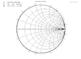
本実施形態にかかるRFコイルの特性をシミュレーションによって解析した結果を図2に示す。図2は、RFコイルに給電ポートを取り付けたときの周波数ごとの複素インピーダンスを表示しており、通常スミスチャートと呼ばれている。 The result of having analyzed the characteristic of the RF coil concerning this embodiment by simulation is shown in FIG. FIG. 2 displays the complex impedance for each frequency when the power feeding port is attached to the RF coil, and is usually called a Smith chart.
まず、実施したシミュレーション方法について説明する。シミュレーションにはCST社の3次元高周波電磁界シミュレーションソフトMICROWAVE STUDIOを用
いて過渡応答解析を行った。RFコイルの二つの垂直バンドの下部それぞれに短いワイヤを取り付け、何も接続されていない二つのワイヤ端同士をつなぐように50Ωにマッチングされた平衡型の給電用ポートを取り付けた。この解析では、給電ポートから高周波パルスを入力しそれに対するRFコイルの応答を、時間領域の電磁界解析手法であるFDTD法を用いて計算を行う。時間領域のパルス入力と結果をフーリエ変換すれば周波数領域の結果を得ることができる。得ることができる結果は、解析対象内の周波数ごとの磁場分布、電場分布、電流分布、それらによるエネルギーの蓄積や損失の発生、給電ポートに対応する応答として周波数ごとの複素インピーダンス(スミスチャート)などである。得られたスミスチャートを解析することでRFコイルの自己共振周波数を求めることができる。また、上記の結果を組み合わせることでRFコイルの性能を評価することも可能である。
First, the implemented simulation method will be described. For the simulation, a transient response analysis was performed using the three-dimensional high-frequency electromagnetic field simulation software MICROWAVE STUDIO of CST. A short wire was attached to each of the lower portions of the two vertical bands of the RF coil, and a balanced power supply port matched to 50Ω was attached so as to connect two wire ends to which nothing was connected. In this analysis, a high frequency pulse is input from the power supply port, and the response of the RF coil is calculated using the FDTD method, which is a time domain electromagnetic field analysis method. If the time domain pulse input and the result are Fourier transformed, the frequency domain result can be obtained. Results that can be obtained include magnetic field distribution, electric field distribution, current distribution for each frequency in the analysis target, energy accumulation and loss caused by them, and complex impedance (Smith chart) for each frequency as a response corresponding to the power supply port. It is. The self-resonant frequency of the RF coil can be obtained by analyzing the obtained Smith chart. In addition, it is possible to evaluate the performance of the RF coil by combining the above results.
シミュレーションと実際に製作したRFコイルの測定値を比較する際には、垂直バンド部と石英管などの筒状の誘電体の間、石英管などの筒状の誘電体とガードリングの間に発生する隙間の大きさ(通常0.1mm未満)まで考慮してシミュレーションを行うとより精度よく解析を行うことができるが、計算メッシュ数が膨大になり計算時間が長くなるため、このような計算は通常行わない。また、隙間等の大きさを考慮したシミュレーションでも、考慮しないシミュレーションでも、RFコイルの形状に依存する自己共振周波数の変化等のような相対値におおよそ乖離は無い。従って、隙間等の大きさを考慮しないシミュレーションによっても精度良く計算することができ、結果は信頼のおけるものである。一方、RFコイルをNMR装置やMRI装置で使用する場合、測定試料によってRFコイルの共振周波数が変わってしまう。これに対応するために調整用のトリマコンデンサをRFコイルに接続することが一般的に行われている。この調整用トリマコンデンサを取り付けるとキャパシタンスが増えるため共振周波数が低下する。したがって、実際のRFコイルの設計、解析、製作ではこれらを考慮してRFコイルの共振周波数を決定する必要がある。 When comparing the simulation and the measured value of the actually manufactured RF coil, it occurs between the vertical band and the cylindrical dielectric such as a quartz tube, or between the cylindrical dielectric such as a quartz tube and the guard ring. If the simulation is performed in consideration of the size of the gap (usually less than 0.1 mm), the analysis can be performed more accurately. However, since the number of calculation meshes becomes enormous and the calculation time becomes long, such calculation is Usually not done. Moreover, there is almost no difference in relative values such as changes in the self-resonant frequency depending on the shape of the RF coil, both in the simulation considering the size of the gap and the like. Therefore, the calculation can be performed with high accuracy even by a simulation that does not consider the size of the gap or the like, and the result is reliable. On the other hand, when the RF coil is used in an NMR apparatus or an MRI apparatus, the resonance frequency of the RF coil varies depending on the measurement sample. In order to cope with this, an adjustment trimmer capacitor is generally connected to the RF coil. When this adjustment trimmer capacitor is attached, the capacitance increases and the resonance frequency decreases. Therefore, it is necessary to determine the resonance frequency of the RF coil in consideration of these in the actual design, analysis, and manufacture of the RF coil.
スミスチャートでは、周波数ごとの複素インピーダンスがひとつの点で表示される。周波数が上昇するにつれて、その点は通常時計回りに移動していく。ある素子のある周波数の複素インピーダンスを示す点がスミスチャートの上半分に存在する場合、その素子はその周波数ではインダクタンス的に振舞うことを示しており、下半分に存在する場合キャパシタンス的に振舞うことを示している。 In the Smith chart, the complex impedance for each frequency is displayed as a single point. As the frequency increases, the point usually moves clockwise. When a point indicating the complex impedance of a certain element is present in the upper half of the Smith chart, it indicates that the element behaves as an inductance at that frequency, and when present in the lower half, it behaves as a capacitance. Show.
実際の素子やそれを解析するシミュレーションの場合、複素インピーダンスが複雑に変化し周波数を上昇させるとスミスチャート上で時計回りに何周もすることがある。これはその素子が周波数領域ごとにさまざまな磁場、電場、電流分布(モード)を持っていることを示している。RFコイルの場合も同様のことが起こるが、RFコイルとして静磁場に垂直な向きに高周波磁場を効率よく作ることができるのは最初のモード、つまりスミスチャートの上半分に存在する周波数領域のうち一番低い周波数領域である。したがって、RFコイルとして使用できる限界を示す自己共振周波数は、周波数の上昇に連れてスミスチャート上を時計周りに回る複素インピーダンスのうち一番最初に右端中央を上から下へ通過する点に対応する周波数となる。 In the case of an actual element or a simulation for analyzing the element, if the complex impedance changes in a complex manner and the frequency is increased, the number of turns may be clockwise on the Smith chart. This indicates that the element has various magnetic fields, electric fields, and current distributions (modes) for each frequency domain. The same thing happens in the case of the RF coil, but the RF coil can efficiently create a high-frequency magnetic field in a direction perpendicular to the static magnetic field in the first mode, that is, in the frequency region existing in the upper half of the Smith chart. This is the lowest frequency region. Therefore, the self-resonant frequency that indicates the limit that can be used as the RF coil corresponds to the point that first passes through the center of the right end from the top to the bottom of the complex impedance that rotates clockwise on the Smith chart as the frequency increases. It becomes frequency.
また、別の見方をすると、本実施形態にかかるRFコイルはインダクタンス(L)とキャパシタンス(C)の並列共振回路とみなすことができる。LC並列共振回路の場合共振周波数では複素インピーダンスが無限大となるため、スミスチャート上では右端中央に位置することになる。 From another point of view, the RF coil according to the present embodiment can be regarded as a parallel resonant circuit of inductance (L) and capacitance (C). In the case of the LC parallel resonance circuit, the complex impedance becomes infinite at the resonance frequency, and therefore, the LC parallel resonance circuit is positioned at the right end center on the Smith chart.
本実施形態にかかるRFコイルのうち、5mmのNMR試料管用に設計したRFコイルについて上記の方法により自己共振周波数を求めた。その結果は、1066MHzであった。一方、従来型の垂直バンドが二つに分割されたAlderman−Grant型で同
様の直径で設計したRFコイルの場合、自己共振周波数は842MHzという結果が得られた。したがって、自己共振周波数が224MHzと大幅に上昇しより高い周波数で使用することができることが確認できた。
Among the RF coils according to the present embodiment, the self-resonant frequency was determined for the RF coil designed for a 5 mm NMR sample tube by the above method. The result was 1066 MHz. On the other hand, in the case of an Alderman-Grant type RF coil designed with the same diameter in which the conventional vertical band is divided into two, a result that the self-resonant frequency is 842 MHz was obtained. Therefore, it was confirmed that the self-resonance frequency was significantly increased to 224 MHz and can be used at a higher frequency.
<第1の実施形態の変形例>
第1の実施形態では、垂直バンド部の形状を直線形状として説明したが、図1Bに示すように、軸方向の先端部13u,13b,14u,14bにおいて先端ほど幅が狭い先細り形状(順テーパ形状)としても良い。図1Bに示すように、ガードリングが存在しない窓部分では直線形状にし、ガードリングが存在する部分において先細り形状としても良いし、窓部分から先細り形状にしても良い。また、先端部に角を設けず、丸みを持たせることも好ましい。このように、角を設けないことで損失を抑制することができる。また、先細り形状とすることで、垂直バンド部とガードリングの間の極板面積をさらに小さくできるので、キャパシタンスを低下させることができる。
<Modification of First Embodiment>
In the first embodiment, the shape of the vertical band portion has been described as a linear shape. However, as shown in FIG. 1B, the
<第2の実施形態:分離ウィング型>
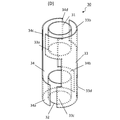
図3Aに、第2の実施形態にかかるRFコイル20の外観を示す。本実施形態では、第1の実施形態のRFコイルの構造に加えて、2つの垂直バンド部23,24の間であってガードリング21,22の周面と対向する位置に、垂直バンドから分離した分離ウィング部25−28が設けられている。その他の構造については、第1の実施形態と同様である。なお、本実施形態にかかるRFコイルを、本明細書中では「分離ウィング型」と称する。
<Second Embodiment: Separation Wing Type>
FIG. 3A shows an appearance of the
2つの垂直バンド部間の合成キャパシタンスのうち、ガードリングを経由しないキャパシタンスに着目すると、Alderman−Grant型コイルではウィング部間の1つのコンデンサ(図20におけるCLR)によるものであるのに対して、本実施形態では垂直バンド部と分離ウィング部の間の直列な2つのコンデンサによるものになる。本実施形態における垂直バンド部と分離ウィングの間のそれぞれの距離が、Alderman−Grant型コイルにおけるウィング部間の距離と等しいとすれば、本実施形態におけるキャパシタンス成分はAlderman−Grant型コイルの半分とすることができる。なお、本実施形態において垂直バンド部と分離ウィング部の間の距離を、Alderman−Grant型コイルの場合の半分よりも大きくすれば、全体的なキャパシタンス成分を小さくすることができる。また、第1の実施形態と同様に垂直バンド部とガードリングの間の極板面積が減少し、キャパシタンスが小さくなるため、自己共振周波数を向上させることができる。 Focusing on the capacitance that does not go through the guard ring among the combined capacitance between the two vertical band parts, in the Alderman-Grant type coil, it is due to one capacitor (C LR in FIG. 20) between the wing parts. In this embodiment, this is due to two capacitors in series between the vertical band portion and the separation wing portion. If each distance between the vertical band part and the separation wing in this embodiment is equal to the distance between the wing parts in the Alderman-Grant type coil, the capacitance component in this embodiment is half that of the Alderman-Grant type coil. can do. In this embodiment, if the distance between the vertical band portion and the separation wing portion is set to be larger than half that in the case of the Alderman-Grant type coil, the overall capacitance component can be reduced. Further, as in the first embodiment, the electrode plate area between the vertical band portion and the guard ring is reduced and the capacitance is reduced, so that the self-resonant frequency can be improved.
本実施形態にかかるRFコイルの特性をシミュレーションによって解析した結果を図4に示す。図4は、RFコイルに給電ポートを取り付けたときの周波数ごとの複素インピーダンスをスミスチャートで示している。本実施形態にかかるRFコイルのうち、5mmのNMR試料管用に設計したRFコイルについて上記の方法により自己共振周波数を求めた。その結果は、1070MHzであった。一方、従来型の垂直バンドが二つに分割されたAlderman−Grant型で同様の直径で設計したRFコイルの場合、自己共振周波数は842MHzという結果が得られた。したがって、自己共振周波数が228MHzと大幅に上昇しより高い周波数で使用することができることが確認できた。 The result of having analyzed the characteristic of the RF coil concerning this embodiment by simulation is shown in FIG. FIG. 4 is a Smith chart showing the complex impedance for each frequency when the power supply port is attached to the RF coil. Among the RF coils according to the present embodiment, the self-resonant frequency was determined for the RF coil designed for a 5 mm NMR sample tube by the above method. The result was 1070 MHz. On the other hand, in the case of an Alderman-Grant type RF coil designed with the same diameter in which the conventional vertical band is divided into two, a result that the self-resonant frequency is 842 MHz was obtained. Therefore, it was confirmed that the self-resonant frequency was significantly increased to 228 MHz and can be used at a higher frequency.
<第2の実施形態の変形例>
第2の実施形態においても、第1の実施形態と同様に、図3Bに示すように、垂直バンド部23,24の軸方向の先端部を先細り形状(順テーパ形状)としても良い。この場合、さらに、図3Cに示すように分離ウィング部25−28の形状を、軸方向の先端ほど幅が広い形状(逆テーパ形状)としても良い。図3Cでは、垂直バンド部23,24と分離ウィング部25−28の間の距離が一定となるように、それぞれが同一のテーパ度合いと
しているが、テーパ度合いは必ずしも同一でなくても構わない。テーパ度合いを異ならせる場合は、先端ほど垂直バンド部と分離ウィングの間の距離が広くなるようにしても良いし、狭くなるようにしても良い。
<Modification of Second Embodiment>
Also in the second embodiment, similarly to the first embodiment, as shown in FIG. 3B, the tip portions in the axial direction of the
また、第2の実施形態において、図5Aに示すように、ガードリング21,22を分割しても良い。この際、ガードリング21,22の分割位置は、分離ウィング部と対向する位置とする。このようにすると、例えばガードリング21を経由する垂直バンド部23,24の間のキャパシタンスに着目すると、4つのコンデンサ(図中のC1−C4)によって直列接続されていることになる。したがって、キャパシタンス成分をより小さくして、自己共振周波数をより高くすることができる。なお、ガードリングを2分割ではなくより多くに分割しても良い。
In the second embodiment, the guard rings 21 and 22 may be divided as shown in FIG. 5A. At this time, the division positions of the guard rings 21 and 22 are the positions facing the separation wing portion. If it does in this way, if it pays attention to the capacitance between the
また、第2の実施形態において、図5Bに示すように、分離ウィング部25−28とガードリング21,22との間の距離d2を、垂直バンド部23,24とガードリング21,22との間の距離d1よりも大きくすることも好ましい。このようにすれば、コイル直径の増大に伴う効率低下の影響を抑制しつつ、分離ウィング部25−28とガードリング21,22との間のキャパシタンスを小さくすることができる。
Further, in the second embodiment, as shown in FIG. 5B, the distance d2 between the separation wing portion 25-28 and the guard rings 21, 22 is set to be equal to the distance between the
また、第2の実施形態において、垂直バンド部間に設けられる分離ウィング部の数は1つではなく2つ以上であっても良い。図16Aに垂直バンド部間に2つの分離ウィング部を設けた場合のRFコイルを示す。この例は、図5Aにおける分離ウィング部25−28をそれぞれ分離ウィング部25a−28aと分離ウィング部25b−28bの2つに分割した変形例と捉えることができる。このようにすることで、RFコイルの合成キャパシタンスを低下させることができる。図16では、垂直バンド部間に2つの分離ウィング部を設ける例を示しているが、垂直バンド部間に3つ以上の分離ウィング部を設けるようにしても構わない。
In the second embodiment, the number of separation wing portions provided between the vertical band portions may be two or more instead of one. FIG. 16A shows an RF coil when two separation wings are provided between vertical band parts. This example can be regarded as a modified example in which the separation wing portion 25-28 in FIG. 5A is divided into two portions, a
また、第2の実施形態において、垂直バンド部にウィング部が設けられていても構わない。図16Bに垂直バンド部にウィング部を設け、これらウィング部の間に垂直バンド部と分離した分離ウィング部を設けたRFコイルを示す。図に示すように、例えば、垂直バンド部23は、上部ガードリング21付近で、垂直バンド部24(より正確には、分離ウィング部25、26)に向かって突出するウィング部23a,23bを備える。ウィング部23a,23bは垂直バンド部23と接続している。同様に、垂直バンド部24は、上部ガードリング21付近で、垂直バンド部23(より正確には、分離ウィング部25,26)に向かって突出するウィング部24a,24bを備える。垂直バンド部の下端も同様である。このようにしても、垂直バンド部間のガードリングを介さないキャパシタンスが、例えば、垂直バンド部23(ウィング部23a)と分離ウィング部25、分離ウィング部25と垂直バンド部24(ウィング部24a)の2つのコンデンサが直接接続された場合と等価であるため、合成キャパシタンスが低下する。
In the second embodiment, a wing portion may be provided in the vertical band portion. FIG. 16B shows an RF coil in which a wing portion is provided in the vertical band portion, and a separation wing portion separated from the vertical band portion is provided between the wing portions. As shown in the figure, for example, the
<第3の実施形態:非対称ウィング型>
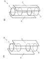
図6Aに、第3の実施形態にかかるRFコイル30の外観を示す。本実施形態では、第1の実施形態のRFコイルにおいて、垂直バンド部33にウィング部33a,33bを設け、垂直バンド部34にウィング部34a,34bを設けている。より具体的には、垂直バンド部33は、下部ガードリング32付近ではストレート形状であるのに対し、上部ガードリング31付近では、上部ガードリングの周面に沿って垂直バンド部34に向かって突出するウィング部33aおよび33bを有する。同様に、垂直バンド部34は、上部ガードリング31付近ではストレート形状であるのに対して、下部ガードリング32付近では、下部ガードリングの周面に沿って垂直バンド部33に向かって突出するウィング部34aおよび34bを有する。
<Third Embodiment: Asymmetric Wing Type>
FIG. 6A shows an appearance of the
Alderman−Grant型コイルでは2つの垂直バンド部から互いにウィング部が突出して向かい合うのに対し、本実施形態では、一方の垂直バンド部はストレート形状であり、他方の垂直バンドにのみウィング部が設けられている。 In the Alderman-Grant type coil, the wings protrude from the two vertical band parts and face each other. In this embodiment, one vertical band part has a straight shape, and the wing part is provided only in the other vertical band. ing.
本実施形態にかかるRFコイルにおいては(Alderman−Grant型コイルと同様に)、例えば、ガードリング31を経由する合成キャパシタンスは、垂直バンド部33とガードリング31の間のコンデンサと、ガードリング31と垂直バンド部34の間のコンデンサの直列接続(図20におけるCLGとCRG)になる。ガードリング31と垂直バンド部34の間の極板面積(キャパシタンス)が他方に比べて十分に小さければ、ガードリング31を経由する合成キャパシタンスは、ガードリング31と垂直バンド部34の間のコンデンサに近い値となる。本実施形態では、垂直バンド部33の上端部にはウィング部を設けるが、垂直バンド部34の上端部にはウィング部を設けていない。したがって、ガードリング31と垂直バンド部34の間のキャパシタンスは小さくなり、ガードリング31を経由する合成キャパシタンスも小さくなる。
In the RF coil according to the present embodiment (similar to the Alderman-Grant type coil), for example, the combined capacitance via the
本実施形態にかかるRFコイルの特性をシミュレーションによって解析した結果を図7に示す。図7は、RFコイルに給電ポートを取り付けたときの周波数ごとの複素インピーダンスをスミスチャートで示している。本実施形態にかかるRFコイルのうち、5mmのNMR試料管用に設計したRFコイルについて上記の方法により自己共振周波数を求めた。その結果は、876MHzであった。一方、従来型の垂直バンドが二つに分割されたAlderman−Grant型で同様の直径で設計したRFコイルの場合、自己共振周波数は842MHzという結果が得られた。したがって、自己共振周波数が小幅ではあるが34MHz上昇しより高い周波数で使用することができることが確認できた。そこで図10(B)のように垂直バンド部のストレート部分を短くしたRFコイルに変更して再度シミュレーションを行った。その結果自己共振周波数は1148MHzまで上昇した。この結果より、本発明ではストレート部分の形状を変更することで容易に自己共振周波数を向上させることができることがわかった。 The result of having analyzed the characteristic of the RF coil concerning this embodiment by simulation is shown in FIG. FIG. 7 is a Smith chart showing the complex impedance for each frequency when the power supply port is attached to the RF coil. Among the RF coils according to the present embodiment, the self-resonant frequency was determined for the RF coil designed for a 5 mm NMR sample tube by the above method. The result was 876 MHz. On the other hand, in the case of an Alderman-Grant type RF coil designed with the same diameter in which the conventional vertical band is divided into two, a result that the self-resonant frequency is 842 MHz was obtained. Therefore, although the self-resonance frequency was small, it was confirmed that it can be used at a higher frequency by 34 MHz. Therefore, as shown in FIG. 10B, the straight band of the vertical band portion was changed to a shortened RF coil, and the simulation was performed again. As a result, the self-resonance frequency increased to 1148 MHz. From this result, it was found that the self-resonant frequency can be easily improved by changing the shape of the straight portion in the present invention.
<第3の実施形態の変形例>
第3の実施形態にかかるRFコイルの形状は種々の変更が可能である。
<Modification of Third Embodiment>
The shape of the RF coil according to the third embodiment can be variously changed.
第3の実施形態においても、第1および第2の実施形態と同様に、図6Bに示すように、垂直バンド部の先端部を先細り形状(順テーパ形状)としても良い。なお、本実施形態の場合は、垂直バンド部のストレート形状を取る端部(ウィング部が設けられていない端部)において、先細り形状とする。また、垂直バンド部のストレート側を先細り形状とする場合には、図6Cに示すように、ウィング部を先端部ほど幅が広い形状(逆テーパ形状)としても良い。図6Cでは、垂直バンド部とウィング部の間の距離が一定となるように、それぞれが同一のテーパ度合いとしているが、テーパ度合いは必ずしも同一でなくても構わない。テーパ度合いを異ならせる場合は、先端ほど垂直バンド部とウィング部の間の距離が広くなるようにしても良いし、狭くなるようにしても良い。 Also in the third embodiment, as in the first and second embodiments, as shown in FIG. 6B, the tip of the vertical band portion may be tapered (forward tapered shape). In the case of the present embodiment, the end of the vertical band portion having a straight shape (the end where no wing portion is provided) is tapered. When the straight side of the vertical band portion is tapered, the wing portion may have a shape that is wider at the tip (reverse taper shape) as shown in FIG. 6C. In FIG. 6C, the taper degree is not necessarily the same, although the taper degree is the same so that the distance between the vertical band part and the wing part is constant. When the degree of taper is varied, the distance between the vertical band part and the wing part may be increased or narrowed toward the tip.
また、ストレート形状を取る側の垂直バンドの形状を、先端に行くほど徐々に幅が細くなるようにする代わりに、先端に行くほど幅が広くなる形状(逆テーパ形状)にしても構わない。この場合は、ウィングをストレート形状にしても良いし、ウィング部の形状を先端に行くほど幅が細くなる形状(順テーパ形状)にしても良い。 Further, the shape of the vertical band on the side that takes the straight shape may be a shape (reverse taper shape) that becomes wider toward the tip instead of being gradually narrowed toward the tip. In this case, the wing may be a straight shape, or the shape of the wing portion may be a shape that becomes narrower toward the tip (forward tapered shape).
また、垂直バンド部とウィング部との間のなす角度は、垂直以外の角度としても構わない。 Further, the angle formed between the vertical band portion and the wing portion may be an angle other than vertical.
また、図6−2Dに示すように、2つの垂直バンド部33,34の両方にウィング部を設けても良い。ただし、上端部においては、垂直バンド部33のウィング部33a,33bとそれぞれ周方向に対向する、垂直バンド部34のウィング部34c,34dの周方向の長さは、ウィング部33a,33bの周方向長さよりも短く設定される。同様に、下端部においては、垂直バンド部34のウィング部34a,34bとそれぞれ周方向に対向する、垂直バンド部33のウィング部33c、33dは、ウィング部34a,34bの周方向長さよりも短く設定される。この変形例は、図6Aに示すRFコイルにおいて、ストレート形状をとる垂直バンド部の端部に、対向する垂直バンド部のウィング部の周方向長さよりも短いウィング部を設けたRFコイルということができる。あるいは、Alderman−Grant型コイルにおいて、対向する2つのウィング部について周方向長さを異ならせたということもできる。なお、図6−2Dでは、上端において垂直バンド部33が有するウィング部の周方向長さを大きくし、垂直バンド部34が有するウィング部の周方向長さを小さくしているが、これは必須ではない。例えば、ウィング部33aの周方向長さをウィング部34cの周方向長さよりも大きくし、ウィング部34dの周方向長さをウィング部33bの周方向長さより大きくしても良い。すなわち、互いに対向するウィング部の周方向長さを異ならせればよい。このようなRFコイルにおいても、垂直バンドとガードリングの間のキャパシタンスに差が生じるので、ガードリングを介した垂直バンド部間の合成キャパシタンスは、Alderman−Grant型コイルのように2つの等しいキャパシタを直列接続した場合よりも小さくなる。なお、ウィング部や垂直バンド部の一部を切り取ってもかまわない。
Further, as shown in FIG. 6D, a wing portion may be provided in both of the two
図6の説明では、それぞれの垂直バンド部が一方の端部においてウィング部を有し、他方の端部においてストレート形状を有するものとして説明した。しかしながら、図17Aに示すように、一方の垂直バンド部は両端においてストレート形状であり、他方の垂直バンド部が両端においてウィングを有しても構わない。より具体的には、一方の垂直バンド部33は、上端および下端の両方においてストレート形状を取るのに対し、他方の垂直バンド部34は、上端において垂直バンド部33に向かって突出するウィング部34a,34bを有し、下端において垂直バンド部33に向かって突出するウィング部34c,34dを有する。なお、ストレート形状の垂直バンド部33の先端をテーパ形状(順テーパおよび逆テーパのいずれも可)としたり、さらにウィング部をテーパ形状(順テーパおよび逆テーパのいずれも可)したりしても構わない。
In the description of FIG. 6, each vertical band portion has been described as having a wing portion at one end portion and having a straight shape at the other end portion. However, as shown in FIG. 17A, one vertical band portion may have a straight shape at both ends, and the other vertical band portion may have wings at both ends. More specifically, one
<その他の変形例>
上記の説明は本発明の実施形態の例示にすぎず、本発明にかかるRFコイルは種々の形態を取ることができる。
<Other variations>
The above description is merely an example of an embodiment of the present invention, and the RF coil according to the present invention can take various forms.
(1.各構造の組合せ)
上記の説明では、2つのガードリング付近での垂直バンド部の形状を同様のものとしたが、それぞれ異なるようにしても良い。例えば、上記第1から第3の実施形態(およびその変形例)を、任意に組み合わせた形状とすることができる。すなわち、一端においてストレート型であり他端において分離ウィング型、一端において分離ウィング型であり他端において非対称ウィング型、一端において非対称ウィング型であり他端においてストレート型を採用しても構わない。
(1. Combination of each structure)
In the above description, the shapes of the vertical band portions in the vicinity of the two guard rings are the same, but they may be different from each other. For example, the first to third embodiments (and modifications thereof) can be arbitrarily combined. That is, a straight type at one end and a separation wing type at the other end, a separation wing type at one end and an asymmetric wing type at the other end, an asymmetric wing type at one end and a straight type at the other end may be adopted.
(2.一端における構造の変形)
さらに、一方のガードリングにおける形状は、上記の説明と異なる形状として構わない。例えば、2つの垂直バンド部の間にガードリングの周面に対向して接続部が設けられており、この接続部によって2つの接続部が接続されて、ガードリングの全周を覆うようにしても構わない。このような形状を接続型と称すると、本発明にかかるRFコイルは、一端においてストレート型であり他端において接続型(図8A)、一端において分離ウィン
グ型であり他端において接続型(図8B)、一端において非対称ウィング型であり他端において接続型(図8C)を採用しても構わない。なお、図8ではストレート型、分離ウィング型および非対称ウィング型の基本形(図1A,3A,6A)と、接続型とを組み合わせた例を示したが、各タイプの変形例(図1B,3B,3C,5A,5B,6B、6Cおよび以下で説明する図9,10,11等)と接続型を組み合わせても良い。
(2. Structural deformation at one end)
Furthermore, the shape of one guard ring may be different from the above description. For example, a connecting portion is provided between two vertical band portions so as to face the peripheral surface of the guard ring, and the two connecting portions are connected by this connecting portion so as to cover the entire circumference of the guard ring. It doesn't matter. When such a shape is referred to as a connection type, the RF coil according to the present invention is a straight type at one end, a connection type at the other end (FIG. 8A), a separation wing type at one end, and a connection type at the other end (FIG. 8B). ), One end may be an asymmetric wing type and the other end may be a connection type (FIG. 8C). 8 shows an example in which the basic type (FIGS. 1A, 3A, 6A) of the straight type, the separation wing type and the asymmetric wing type is combined with the connection type, but each type of modification (FIGS. 1B, 3B, 3C, 5A, 5B, 6B, 6C and FIGS. 9, 10, and 11 described below) and the connection type may be combined.
(3.垂直バンド部の短縮化)
また、上記の説明では、垂直バンド部の上端位置が上部ガードリングの上端位置と等しく、垂直バンド部の下端位置が下部ガードリングの下端位置と等しいものとして説明したが、垂直バンド部の長さはこれよりも短くしても構わない。特に、垂直バンド部の先端形状がストレート型(テーパ形状を含む)の場合には、垂直バンド部の端部位置をガードリングの端部位置と異なるようにしてキャパシタンスをより小さくすることも好ましい。ストレート型、分離ウィング型、非対称ウィング型のそれぞれにおける変形例を、図9に示す。
(3. Shortening of vertical band)
In the above description, the upper end position of the vertical band portion is equal to the upper end position of the upper guard ring, and the lower end position of the vertical band portion is equal to the lower end position of the lower guard ring. May be shorter than this. In particular, when the tip shape of the vertical band portion is a straight type (including a taper shape), it is also preferable to make the capacitance smaller by making the end position of the vertical band portion different from the end position of the guard ring. FIG. 9 shows a modification of each of the straight type, separation wing type, and asymmetric wing type.
図9Aは、ストレート型において垂直バンド部を短くした構成である。すなわち、垂直バンド部13,14の上端位置13u,14uを、上部ガードリング11の上端位置11uより低い位置としている。同様に、垂直バンド部13,14の下端位置13b、14bを、下部ガードリング12の下端位置12bより高い位置としている。なお、図9Aでは、垂直バンド部13,14の上端位置13u,14uを、ガードリング11の下端位置11bよりも高い位置としているが、これは必ずしも必須ではなく、上部ガードリング11の下端位置11bよりも低い位置であっても構わない。同様に、垂直バンド部13,14の下端位置13b,14bも、下部ガードリング12の上端位置12uよりも高い位置であっても構わない。このような構成により、垂直バンド部とガードリングの間の極板面積を小さくできるので、キャパシタンス成分をより小さくできる。
FIG. 9A shows a configuration in which the vertical band portion is shortened in the straight type. That is, the upper end positions 13 u and 14 u of the
図9Bは、分離ウィング型において垂直バンド部を短くした構成である。図9Aの構成と基本的に同様であるので詳細な説明は省略する。図9Cは、非対称ウィング型において、ストレート形状を取る垂直バンド部の端部(ウィング部が設けられていない端部)の上下方向の長さを短くしている。ウィング部が設けられる端部の位置は、ガードリングの端部位置と一致するようにしているが、ウィング部の端部位置についても必ずしもガードリングと一致させなくても構わない。 FIG. 9B shows a configuration in which the vertical band portion is shortened in the separation wing type. Since it is basically the same as the configuration of FIG. 9A, detailed description is omitted. FIG. 9C shows the asymmetric wing type in which the vertical length of the vertical band portion (the end portion where no wing portion is provided) in the straight shape is shortened. The position of the end portion where the wing portion is provided is made to coincide with the end portion position of the guard ring, but the end portion position of the wing portion may not necessarily coincide with the guard ring.
第3の実施形態のシミュレーション結果の説明の欄で説明したように、垂直バンド部の長さを調整することで、RFコイルの自己共振周波数を容易に調整することができる。Alderman−Grant型コイルでは、静磁場の均一度に与える影響等を考慮すると、コイル形状を調整できる余裕が少ないのに対して、本発明にかかるRFコイルではこのような調整の余地が大きい点で有利である。 As described in the description of the simulation result of the third embodiment, the self-resonant frequency of the RF coil can be easily adjusted by adjusting the length of the vertical band portion. In the Alderman-Grant type coil, considering the influence on the uniformity of the static magnetic field, etc., there is little room for adjusting the coil shape, whereas the RF coil according to the present invention has a large room for such adjustment. It is advantageous.
(4.ウィング部の接続)
また、分離ウィング型において、垂直バンド部の長さを短くした場合には、図10Aに示すように、空き領域(垂直バンド部が存在しないガードリングの周面)を用いて、ウィング部を接続させても構わない。図10Aでは、分離ウィング部25、26を接続する接続リング25aが、ガードリング21の上端部分を取り囲むように設けられている。同様に、下部ガードリング22の下端部分を取り囲むように設けられた接続リング27aによって、分離ウィング部27,28を接続する。このように接続リング部を設けることで、分離ウィング部の固定が容易となる。
(4. Connection of wing part)
In the case of the separation wing type, when the length of the vertical band portion is shortened, as shown in FIG. 10A, the wing portion is connected using an empty area (a peripheral surface of the guard ring where no vertical band portion exists). It does n’t matter. In FIG. 10A, a
非対称ウィング型において、垂直バンド部の長さを短くした場合も、上記と同様に図10Bに示すように、空き領域を用いてウィング部を接続させても構わない。図10Bでは
、垂直バンド部33は、上部ガードリング31付近でウィング部33aおよび33bを有するが、これらのウィング部33aおよび33bを接続する接続部33cが空き領域に設けられる。同様に、垂直バンド部34は、下部ガードリング32付近において、ウィング部34aおよび34bを接続する接続部34cを、下部ガードリング32の周囲に有する。このように接続部33c、34cを有することで、ウィング部の固定が容易となる。
In the asymmetric wing type, even when the length of the vertical band portion is shortened, the wing portion may be connected using an empty area as shown in FIG. 10B as described above. In FIG. 10B, the
また、図17Aに示すような非対称ウィング型の変形例においても、同様に図17Bに示すようにウィング部を接続できる。この例では、垂直バンド部33は長さが短いストレート型であり、垂直バンド部33の上下端は、ガードリングの上下端よりも内側である。また、垂直バンド部34が上端においてウィング部34a,34bを有しており、下端においてウィング部34c,34dを有している。そして、空き領域を用いてウィング部34a,34bを接続する接続部34eがガードリング31の周囲に設けられ、ウィング部34c,34dを接続する接続部34fがガードリング32の周囲に設けられる。
Also in the asymmetric wing type modification as shown in FIG. 17A, the wing portions can be similarly connected as shown in FIG. 17B. In this example, the
(5.垂直バンド部端部の変形)
また、垂直バンド部のストレート形状を取る端部について、ガードリングとの間の距離をより大きくすることも好ましい。図11Aは、ストレート型のRFコイルにおいて、垂直バンド13,14の下部ガードリング12側の端部13e,14eは、ガードリング12からの距離が垂直バンド部の本体部13g,14gよりも離れた構造となっている。なお、端部13e,14eは、本体部13g,14gと平行である。また、本体部13g、14gと端部13e,14eを接続するための、接続部13f、14fも設けられる。図11Aでは、接続部13f,14fは、本体部13g、14gや端部13e,14eと直交するように描いているが、必ずしも直交させる必要は無い。また、角を丸めるようにしても良い。このように端部を設けることで、給電ポートの取り付け部分を下端にすることができ、かつ、垂直バンド部とガードリングとの間のキャパシタンスを小さくすることができる。
(5. Deformation of vertical band end)
It is also preferable to increase the distance from the guard ring at the end portion of the vertical band portion having a straight shape. FIG. 11A shows a straight type RF coil in which the
図11Bおよび図11Cは、それぞれ分離ウィング型および非対称ウィング型に同様の変形を施した例である。図11Bの分離ウィング型では、垂直バンド部23,24のそれぞれが、下部ガードリング22付近において、端部23e,24eはガードリング22との距離が大きくなった構造を有する。また、図11Cの非対称ウィング型では、下部ガードリング付近においてストレート形状を取る垂直バンド部33の端部33eが、下部ガードリング32との距離が大きくなった構造を有する。
FIG. 11B and FIG. 11C are examples in which the same modification is applied to the separation wing type and the asymmetric wing type, respectively. In the separation wing type of FIG. 11B, each of the
なお、図11A−図11Cに示すように、垂直バンド部の端部においてガードリングからの距離を離した場合には、この部分に、図10A,図10Bに示したようにウィング部を接続する接続部を設けることもできる。 As shown in FIGS. 11A to 11C, when the distance from the guard ring is increased at the end of the vertical band part, the wing part is connected to this part as shown in FIGS. 10A and 10B. A connection can also be provided.
(6.ガードリング形状および垂直バンド部形状の変形)
また、ガードリングは円筒形状であるとして説明したが、楕円筒形状であっても構わないし、多角形筒形状であっても構わない。また、垂直バンド部の形状も、円弧筒形状(楕円弧筒形状を含む)に限られず、平板形状であっても構わないし、複数の平板を組み合わせた形状であっても構わない。図12Aにストレート型のRFコイルにおいて、垂直バンド部の形状を平板形状とする例を示した。また、図12Bに、ストレート型のRFコイルにおいて、垂直バンド部の形状を、2つの平板を組み合わせた形状とする例を示した。ここで説明した、ガードリングの形状および垂直バンド部の形状は、任意に組み合わせて構わない。図12では、ストレート型のRFコイルに対する変形例を示したが、その他のタイプに対しても同様の変形は可能である。
(6. Deformation of guard ring shape and vertical band part shape)
Further, although the guard ring has been described as having a cylindrical shape, it may have an elliptical cylindrical shape or a polygonal cylindrical shape. Further, the shape of the vertical band portion is not limited to the arc tube shape (including the elliptic arc tube shape), and may be a flat plate shape or a shape in which a plurality of flat plates are combined. FIG. 12A shows an example in which the shape of the vertical band portion is a flat plate shape in a straight type RF coil. FIG. 12B shows an example in which the shape of the vertical band portion is a shape obtained by combining two flat plates in a straight type RF coil. The shape of the guard ring and the shape of the vertical band portion described here may be arbitrarily combined. Although FIG. 12 shows a modification of the straight type RF coil, the same modification is possible for other types.
(7.ガードリングと垂直バンド部の位置の変形)
また、上記の説明では、ガードリングの外側に垂直バンド部が設けられるものとして説明したが、垂直バンド部はガードリングの内側に設けられても構わない。図13A−図13Cに、それぞれストレート型、分離ウィング型、非対称ウィング型において、垂直バンド部をガードリングの内側に設けたRFコイルの例を示す。また、給電ポートを、垂直バンド部の上端と下端に設ける場合や、ガードリングの上端と下端に設ける場合には、このような構成にすることが好ましい。
(7. Deformation of guard ring and vertical band part)
In the above description, the vertical band portion is provided outside the guard ring. However, the vertical band portion may be provided inside the guard ring. FIG. 13A to FIG. 13C show examples of RF coils in which a vertical band portion is provided inside a guard ring in a straight type, a separated wing type, and an asymmetric wing type, respectively. In addition, when the power supply ports are provided at the upper end and the lower end of the vertical band portion, or when provided at the upper end and the lower end of the guard ring, such a configuration is preferable.
また、図17A,図17Bに示すRFコイルにおいて、垂直バンド部をガードリングの内側に設けた変形例を図17C、図17Dにそれぞれ示す。 In addition, in the RF coil shown in FIGS. 17A and 17B, modifications in which the vertical band portion is provided inside the guard ring are shown in FIGS. 17C and 17D, respectively.
(8.スリット部の付加)
また、窓部分(ガードリングがない部分)において垂直バンド部にスリット部を設けても構わない。こうすることで、他のRFコイルを用いて異なる周波数の磁場を印加することができる。複数の周波数を用いる場合には、1つのRFコイルでは対応できなくなるので、スリット部を設けたRFコイルの外側に、向きが90度異なるRFコイルを取り付ける。外側RFコイルの高周波磁場はスリットのすき間を通して測定試料に照射される。窓部分においてスリットが設けられればスリット部の形状はどのようなものであって構わない。一例を図14A−図14Cに示す。図14A―図14Cは、それぞれストレート型、分離ウィング型、非対称ウィング型において、垂直バンド部にスリット部を設けたRFコイルの例を示す図である。ここでは、垂直バンド部の上端から窓部分に至るスリット部を設けている。なお、スリット部の形状は種々変形が可能である。一例として図15Aに示すように、スリット部の下端位置13sbを下部ガードリング12の上端位置12uよりも低くしても良い。また、図15Bに示すように、スリット部をより長くして、垂直バンド部を2つに分割してしまっても良い。また、図15Cに示すように、スリット部の幅をガードリング付近と窓付近とで異なるようにして、窓付近でのスリット幅をより広くするようにしても良い。図15の各例はストレート型に対する変形のみを示しているが、分離ウィング型や非対称ウィング型にも同様の変形が適用可能である。
(8. Addition of slit part)
Moreover, you may provide a slit part in a vertical band part in a window part (part without a guard ring). By doing so, magnetic fields of different frequencies can be applied using other RF coils. When a plurality of frequencies are used, one RF coil cannot be used. Therefore, RF coils whose directions are different by 90 degrees are attached to the outside of the RF coil provided with the slit portion. The high frequency magnetic field of the outer RF coil is irradiated to the measurement sample through the slit gap. As long as a slit is provided in the window portion, the slit portion may have any shape. An example is shown in FIGS. 14A-14C. 14A to 14C are diagrams showing examples of RF coils in which a slit portion is provided in a vertical band portion in a straight type, a separated wing type, and an asymmetric wing type, respectively. Here, a slit portion extending from the upper end of the vertical band portion to the window portion is provided. Note that the shape of the slit portion can be variously modified. As an example, as shown in FIG. 15A, the
(9.その他)
また、上記の説明では、1.03GHz超の高周波磁場を印加するための、直径5mm試料管用のRFコイル(RFコイルの最小内径が5.4mm程度から10mm)を例として説明したが、本発明にかかるRFコイルが印加する磁場の周波数は1.03GHzよりも高くても低くても構わないし、RFコイルの直径は上記範囲よりも大きくても小さくても構わない。他の条件を一定として本発明にRFコイルの形状を用いることで、コイルの直径や磁場生成効率などを低下させることなく、RFコイルの自己共振周波数を向上させることができる。したがって、静磁場強度を向上させた場合に受信感度を悪化させることなく、より高い周波数の高周波磁場を送信もしくは受信することができる。
(9. Other)
In the above description, an RF coil for a sample tube having a diameter of 5 mm for applying a high frequency magnetic field exceeding 1.03 GHz (the minimum inner diameter of the RF coil is about 5.4 mm to 10 mm) has been described as an example. The frequency of the magnetic field applied by the RF coil may be higher or lower than 1.03 GHz, and the diameter of the RF coil may be larger or smaller than the above range. By using the shape of the RF coil in the present invention under other conditions, the self-resonant frequency of the RF coil can be improved without reducing the coil diameter, magnetic field generation efficiency, and the like. Therefore, when the static magnetic field strength is improved, a high frequency magnetic field with a higher frequency can be transmitted or received without deteriorating the reception sensitivity.
また、上記の説明では、1つのRFコイルを用いて核磁気共鳴現象の励起(高周波磁場の送信)と、核磁気共鳴現象の検出(NMR信号の受信)を行っているが、それぞれを異なるRFコイルで行っても構わない。本発明にかかるRFコイルは、励起と検出のために共用されるコイル以外にも、励起用のコイルおよび検出用のコイルのいずれにも用いることができる。 In the above description, the excitation of the nuclear magnetic resonance phenomenon (transmission of the high-frequency magnetic field) and the detection of the nuclear magnetic resonance phenomenon (reception of the NMR signal) are performed using one RF coil. You may do with a coil. The RF coil according to the present invention can be used for both an excitation coil and a detection coil in addition to a coil shared for excitation and detection.
また、上記の説明では、溶液NMR装置を例に説明したが、本発明にかかるRFコイルは固体NMR装置にも適用することもできる。また、核磁気共鳴現象を用いて生体の内部情報を画像化するMRI(核磁気共鳴画像法)装置も、装置の大きさや印加する磁場の大きさ等では異なるものの、測定原理はNMR装置と同一である。したがって、本発明にかかるRFコイルはMRI装置にも適用することができる。MRI装置で用いられる静磁場強度は数T程度であるが、RFコイルの直径も大きいためRFコイルの自己共振周波数も
小さくなる。静磁場強度を増加させた場合に、コイルの大きさを小さくしたりすることなく自己共振周波数を向上させるために、本発明にかかるRFコイルは有用である。
In the above description, the solution NMR apparatus has been described as an example. However, the RF coil according to the present invention can also be applied to a solid-state NMR apparatus. In addition, an MRI (nuclear magnetic resonance imaging) apparatus that images internal information of a living body using a nuclear magnetic resonance phenomenon is different in the size of the apparatus and the magnitude of a magnetic field to be applied, but the measurement principle is the same as the NMR apparatus. It is. Therefore, the RF coil according to the present invention can also be applied to an MRI apparatus. The static magnetic field strength used in the MRI apparatus is about several T, but since the diameter of the RF coil is large, the self-resonant frequency of the RF coil is also small. The RF coil according to the present invention is useful for improving the self-resonance frequency without increasing the size of the coil when the static magnetic field strength is increased.
また、上記の説明では、垂直バンド部間にチップコンデンサを設けていないが、非特許文献1等に記載されるように、垂直バンド部同士をチップコンデンサによって接続しても構わない。チップコンデンサを用いることでRFコイルの形状の保持に役立つし、コイルのみではキャパシタンスが不十分になる場合に補うことができる。
In the above description, the chip capacitor is not provided between the vertical band portions. However, as described in
上記で説明した変形例は、技術的に矛盾の生じない限り、第1から第3の実施形態の任意の形態と組み合わせたり、また変形例同士を組み合わせたりしても構わない。また、上部および下部のガードリング付近における垂直バンド部や分離ウィング部などの形状は、上記で説明した各種の実施形態および変形例の構造を、任意に組み合わせることができる。すなわち、垂直バンド部に着目すると、2つの垂直バンド部の上端および下端の4つの端部に関して、各種の構造を任意に採用することができる。 The modifications described above may be combined with any form of the first to third embodiments or may be combined with each other as long as there is no technical contradiction. In addition, the shapes of the vertical band part and the separation wing part in the vicinity of the upper and lower guard rings can be arbitrarily combined with the structures of the various embodiments and modifications described above. That is, when paying attention to the vertical band portion, various structures can be arbitrarily adopted for the four end portions of the upper end and the lower end of the two vertical band portions.
10,20,30 RFコイル
11,12,21,22,31,32 ガードリング
13,14,23,24,33,34 垂直バンド部
25,26,27,28 分離ウィング部
33a,33b,34a,34b ウィング部
10, 20, 30
Claims (8)
外形がほぼ円筒形または楕円筒形または多角筒形をしており、前記円筒または楕円筒または多角筒の軸方向に離間して設けられた2つのガードリングと、
前記軸方向に延びるほぼ直線形状またはテーパ形状の第1および第2の垂直バンド部であって、前記2つのガードリングを挟んで互いに対向して設けられた第1および第2の垂直バンド部と、
を備え、
前記2つのガードリングの少なくとも一方のガードリングの周面と対向する位置の、周方向に沿った前記第1および第2の垂直バンド部の間に、これらの垂直バンド部と分離して設けられた分離ウィング部をさらに備える、
RFコイル。 An RF coil for exciting or detecting a nuclear magnetic resonance phenomenon,
Two guard rings having an outer shape that is substantially cylindrical, elliptical, or polygonal, and spaced apart in the axial direction of the cylinder, elliptical, or polygonal;
First and second vertical band portions having substantially linear or tapered shapes extending in the axial direction, the first and second vertical band portions being opposed to each other with the two guard rings interposed therebetween; ,
With
Between the first and second vertical band portions in the circumferential direction at a position facing the peripheral surface of at least one guard ring of the two guard rings, the vertical band portions are provided separately from the first and second vertical band portions. Further comprising a separate wing part,
RF coil.
請求項1に記載のRFコイル。 A capacitor is formed between the vertical band part and the separation wing part.
The RF coil according to claim 1 .
請求項1または2に記載のRFコイル。 The two guard rings are divided at a position facing the separation wing part,
The RF coil according to claim 1 or 2.
請求項1から3のいずれかに記載にRFコイル。 The separation wing portion is provided at a position farther from the guard ring as compared to the first and second vertical band portions.
The RF coil according to claim 1.
請求項1〜4のいずれかに記載のRFコイル。 The length of the first and second vertical band portions in the axial direction is shorter than the length between the upper end and the lower end of the two guard rings, and the first and second vertical bands at the upper end or the lower end of the guard ring. Having a portion not facing the band,
The RF coil in any one of Claims 1-4.
られる、
請求項5に記載のRFコイル。 At the upper end or lower end of the guard ring that does not face the first and second vertical bands, a connecting portion that connects the separation wing portion is provided at a position facing the peripheral surface of the guard ring.
The RF coil according to claim 5.
請求項1〜6のいずれかに記載のRFコイル。 A plurality of separation wing portions which are positions facing the peripheral surface of the guard ring and are separated from these vertical band portions and separated from each other between the first and second vertical band portions. ,
The RF coil according to claim 1.
Priority Applications (2)
| Application Number | Priority Date | Filing Date | Title |
|---|---|---|---|
| JP2012148036A JP6048868B2 (en) | 2012-06-29 | 2012-06-29 | RF coil for measuring nuclear magnetic resonance phenomena |
| EP13174124.1A EP2680022B9 (en) | 2012-06-29 | 2013-06-27 | Radiofrequency coil for measurement of nuclear magnetic resonance |
Applications Claiming Priority (1)
| Application Number | Priority Date | Filing Date | Title |
|---|---|---|---|
| JP2012148036A JP6048868B2 (en) | 2012-06-29 | 2012-06-29 | RF coil for measuring nuclear magnetic resonance phenomena |
Publications (3)
| Publication Number | Publication Date |
|---|---|
| JP2014010090A JP2014010090A (en) | 2014-01-20 |
| JP2014010090A5 JP2014010090A5 (en) | 2015-08-20 |
| JP6048868B2 true JP6048868B2 (en) | 2016-12-21 |
Family
ID=49110972
Family Applications (1)
| Application Number | Title | Priority Date | Filing Date |
|---|---|---|---|
| JP2012148036A Active JP6048868B2 (en) | 2012-06-29 | 2012-06-29 | RF coil for measuring nuclear magnetic resonance phenomena |
Country Status (2)
| Country | Link |
|---|---|
| EP (1) | EP2680022B9 (en) |
| JP (1) | JP6048868B2 (en) |
Families Citing this family (5)
| Publication number | Priority date | Publication date | Assignee | Title |
|---|---|---|---|---|
| JP6341535B2 (en) | 2014-04-30 | 2018-06-13 | 株式会社エム・アール・テクノロジー | Imaging unit |
| KR102277899B1 (en) | 2014-08-11 | 2021-07-15 | 삼성전자주식회사 | Radio frequency coil and Magnetic resonance imaging system comprising the radio frequency coil |
| CN104483641B (en) * | 2014-12-19 | 2017-04-12 | 中国科学院武汉物理与数学研究所 | Electronic-nuclear double-resonance resonator |
| TWI626461B (en) | 2015-05-12 | 2018-06-11 | Hyperfine Research, Inc. | Radio frequency coils, radio frequency components and apparatuses comprising the same, and methods of determining configurations for the same |
| CN106405458B (en) * | 2016-08-30 | 2020-01-14 | 凯思轩达医疗科技无锡有限公司 | Scanning coil for nuclear magnetic resonance |
Family Cites Families (12)
| Publication number | Priority date | Publication date | Assignee | Title |
|---|---|---|---|---|
| US4641097A (en) * | 1984-05-10 | 1987-02-03 | General Electrtic Company | Elliptical cross-section slotted-tube radio-frequency resonator for nuclear magnetic resonance imaging |
| JPH0331047Y2 (en) * | 1985-04-03 | 1991-07-01 | ||
| JPH0446727Y2 (en) * | 1987-01-13 | 1992-11-04 | ||
| US4875013A (en) * | 1987-03-13 | 1989-10-17 | Hitachi, Ltd. | High-frequency coil for nuclear magnetic imaging |
| JPH01285253A (en) * | 1988-05-13 | 1989-11-16 | Hitachi Ltd | Probe for examination apparatus using nuclear magnetic resonance |
| JPH02195938A (en) * | 1989-01-25 | 1990-08-02 | Hitachi Ltd | Probe for nuclear magnetic resonance equipment |
| JP2865375B2 (en) * | 1990-05-14 | 1999-03-08 | 株式会社東芝 | Quadrature coil device |
| JP2638420B2 (en) * | 1993-02-28 | 1997-08-06 | 株式会社島津製作所 | Quadrature coil for MRI equipment |
| DE19733574C2 (en) * | 1997-08-02 | 2000-04-06 | Bruker Ag | Superconducting hybrid resonator for receiving NMR signals |
| CA2334929A1 (en) * | 2000-02-10 | 2001-08-10 | Jarod Matwiy | Quadrature rf field coil for use in magnetic resonance |
| US7132829B2 (en) * | 2005-01-18 | 2006-11-07 | Varian, Inc. | NMR RF coils with improved low-frequency efficiency |
| US7106063B1 (en) * | 2005-08-05 | 2006-09-12 | Varian, Inc. | Axially constrained RF probe coil |
-
2012
- 2012-06-29 JP JP2012148036A patent/JP6048868B2/en active Active
-
2013
- 2013-06-27 EP EP13174124.1A patent/EP2680022B9/en not_active Not-in-force
Also Published As
| Publication number | Publication date |
|---|---|
| EP2680022A3 (en) | 2014-03-19 |
| EP2680022A2 (en) | 2014-01-01 |
| JP2014010090A (en) | 2014-01-20 |
| EP2680022B1 (en) | 2017-12-06 |
| EP2680022B9 (en) | 2018-02-07 |
Similar Documents
| Publication | Publication Date | Title |
|---|---|---|
| US8421462B2 (en) | Sinusoidally resonant radio frequency volume coils for high field magnetic resonance applications | |
| JP4155988B2 (en) | Birdcage coil and NMR system | |
| US8106657B2 (en) | Apparatus for high-resolution NMR spectroscopy and/or imaging with an improved filling factor and RF field amplitude | |
| US4590427A (en) | Nuclear magnetic resonance apparatus having semitoroidal rf coil for use in topical NMR and NMR imaging | |
| JP4426975B2 (en) | Crushed liquid NMR sample tube and RF coil | |
| JP6048868B2 (en) | RF coil for measuring nuclear magnetic resonance phenomena | |
| JPWO2008075614A1 (en) | Nuclear magnetic resonance measuring apparatus and coil unit | |
| Zhang et al. | Higher‐order harmonic transmission‐line RF coil design for MR applications | |
| US9287606B2 (en) | Dual-mode microwave resonator device and method of electron spin resonance measurement | |
| US20090085567A1 (en) | Magnetic resonance apparatus with shim arrangement | |
| RU2597068C2 (en) | Transverse-electromagnetic (tem) radio-frequency coil for magnetic resonance | |
| Badilita et al. | Microfabricated inserts for magic angle coil spinning (MACS) wireless NMR spectroscopy | |
| JP5355584B2 (en) | Antenna apparatus and magnetic resonance inspection apparatus | |
| US20200292647A1 (en) | Slotted waveguide array rf coil for magnetic resonance systems | |
| Rinard et al. | Resonators for in vivo imaging: practical experience | |
| CN103018689A (en) | Design method for magnetic resonance radio-frequency coil based on stream function | |
| CN115184849B (en) | High-resolution magnetic field measuring device based on NMR probe | |
| Lu et al. | Low‐cost inductively coupled stacked wireless RF coil for MRI at 3 T | |
| JP2009276340A (en) | Nmr probe | |
| Shajan et al. | Rat brain MRI at 16.4 T using a capacitively tunable patch antenna in combination with a receive array | |
| CN104155622B (en) | A kind of planar radio frequency coils for nuclear magnetic resonance | |
| Utz et al. | Nuclear magnetic resonance in microfluidic environments using inductively coupled radiofrequency resonators | |
| Avdievich et al. | 7T head volume coils: improvements for rostral brain imaging | |
| Noohi et al. | A flexible rectangular PCB coil to excite uniform magnetic field in nuclear magnetic resonance spectroscopy: design, optimization and implementation | |
| Stara et al. | Quadrature birdcage coil with distributed capacitors for 7.0 T magnetic resonance data acquisition of small animals |
Legal Events
| Date | Code | Title | Description |
|---|---|---|---|
| A521 | Request for written amendment filed |
Free format text: JAPANESE INTERMEDIATE CODE: A523 Effective date: 20150626 |
|
| A621 | Written request for application examination |
Free format text: JAPANESE INTERMEDIATE CODE: A621 Effective date: 20150626 |
|
| A977 | Report on retrieval |
Free format text: JAPANESE INTERMEDIATE CODE: A971007 Effective date: 20160328 |
|
| A131 | Notification of reasons for refusal |
Free format text: JAPANESE INTERMEDIATE CODE: A131 Effective date: 20160412 |
|
| A521 | Request for written amendment filed |
Free format text: JAPANESE INTERMEDIATE CODE: A523 Effective date: 20160613 |
|
| A131 | Notification of reasons for refusal |
Free format text: JAPANESE INTERMEDIATE CODE: A131 Effective date: 20160823 |
|
| A521 | Request for written amendment filed |
Free format text: JAPANESE INTERMEDIATE CODE: A523 Effective date: 20160909 |
|
| TRDD | Decision of grant or rejection written | ||
| A01 | Written decision to grant a patent or to grant a registration (utility model) |
Free format text: JAPANESE INTERMEDIATE CODE: A01 Effective date: 20161025 |
|
| A61 | First payment of annual fees (during grant procedure) |
Free format text: JAPANESE INTERMEDIATE CODE: A61 Effective date: 20161111 |
|
| R150 | Certificate of patent or registration of utility model |
Ref document number: 6048868 Country of ref document: JP Free format text: JAPANESE INTERMEDIATE CODE: R150 |
|
| R250 | Receipt of annual fees |
Free format text: JAPANESE INTERMEDIATE CODE: R250 |
|
| R250 | Receipt of annual fees |
Free format text: JAPANESE INTERMEDIATE CODE: R250 |
|
| R250 | Receipt of annual fees |
Free format text: JAPANESE INTERMEDIATE CODE: R250 |
|
| R250 | Receipt of annual fees |
Free format text: JAPANESE INTERMEDIATE CODE: R250 |
|
| R250 | Receipt of annual fees |
Free format text: JAPANESE INTERMEDIATE CODE: R250 |
|
| R250 | Receipt of annual fees |
Free format text: JAPANESE INTERMEDIATE CODE: R250 |