JP6046051B2 - Automatic feeder for industrial metal steam generators. - Google Patents
Automatic feeder for industrial metal steam generators. Download PDFInfo
- Publication number
- JP6046051B2 JP6046051B2 JP2013548844A JP2013548844A JP6046051B2 JP 6046051 B2 JP6046051 B2 JP 6046051B2 JP 2013548844 A JP2013548844 A JP 2013548844A JP 2013548844 A JP2013548844 A JP 2013548844A JP 6046051 B2 JP6046051 B2 JP 6046051B2
- Authority
- JP
- Japan
- Prior art keywords
- metal
- pot
- pipe
- evaporation
- valve
- Prior art date
- Legal status (The legal status is an assumption and is not a legal conclusion. Google has not performed a legal analysis and makes no representation as to the accuracy of the status listed.)
- Active
Links
- 229910052751 metal Inorganic materials 0.000 title claims description 83
- 239000002184 metal Substances 0.000 title claims description 83
- 238000001704 evaporation Methods 0.000 claims description 89
- 230000008020 evaporation Effects 0.000 claims description 88
- 238000002844 melting Methods 0.000 claims description 57
- 230000008018 melting Effects 0.000 claims description 55
- 229910001338 liquidmetal Inorganic materials 0.000 claims description 45
- 238000010438 heat treatment Methods 0.000 claims description 39
- FYYHWMGAXLPEAU-UHFFFAOYSA-N Magnesium Chemical compound [Mg] FYYHWMGAXLPEAU-UHFFFAOYSA-N 0.000 claims description 22
- 229910052749 magnesium Inorganic materials 0.000 claims description 22
- 239000011777 magnesium Substances 0.000 claims description 22
- 238000009434 installation Methods 0.000 claims description 20
- 238000000151 deposition Methods 0.000 claims description 17
- 238000009826 distribution Methods 0.000 claims description 17
- 230000008021 deposition Effects 0.000 claims description 16
- 239000011248 coating agent Substances 0.000 claims description 15
- 238000000576 coating method Methods 0.000 claims description 15
- 239000007788 liquid Substances 0.000 claims description 15
- 238000000034 method Methods 0.000 claims description 15
- 239000007787 solid Substances 0.000 claims description 12
- HCHKCACWOHOZIP-UHFFFAOYSA-N Zinc Chemical compound [Zn] HCHKCACWOHOZIP-UHFFFAOYSA-N 0.000 claims description 9
- 239000000463 material Substances 0.000 claims description 9
- 229910052725 zinc Inorganic materials 0.000 claims description 9
- 239000011701 zinc Substances 0.000 claims description 9
- 238000001816 cooling Methods 0.000 claims description 8
- OKTJSMMVPCPJKN-UHFFFAOYSA-N Carbon Chemical compound [C] OKTJSMMVPCPJKN-UHFFFAOYSA-N 0.000 claims description 7
- 229910002804 graphite Inorganic materials 0.000 claims description 7
- 239000010439 graphite Substances 0.000 claims description 7
- 239000000758 substrate Substances 0.000 claims description 7
- 238000001771 vacuum deposition Methods 0.000 claims description 7
- 229910001209 Low-carbon steel Inorganic materials 0.000 claims description 6
- 238000001912 gas jet deposition Methods 0.000 claims description 6
- 239000010935 stainless steel Substances 0.000 claims description 5
- 229910001220 stainless steel Inorganic materials 0.000 claims description 5
- 239000011261 inert gas Substances 0.000 claims description 3
- 238000002347 injection Methods 0.000 claims description 3
- 239000007924 injection Substances 0.000 claims description 3
- 239000002826 coolant Substances 0.000 claims description 2
- 230000001105 regulatory effect Effects 0.000 claims description 2
- 229910003564 SiAlON Inorganic materials 0.000 claims 1
- 230000008878 coupling Effects 0.000 claims 1
- 238000010168 coupling process Methods 0.000 claims 1
- 238000005859 coupling reaction Methods 0.000 claims 1
- XKRFYHLGVUSROY-UHFFFAOYSA-N Argon Chemical compound [Ar] XKRFYHLGVUSROY-UHFFFAOYSA-N 0.000 description 14
- 229910052786 argon Inorganic materials 0.000 description 7
- 239000012535 impurity Substances 0.000 description 7
- 230000006698 induction Effects 0.000 description 6
- 238000011049 filling Methods 0.000 description 4
- 239000010953 base metal Substances 0.000 description 3
- 238000005259 measurement Methods 0.000 description 3
- 239000000523 sample Substances 0.000 description 3
- 238000000926 separation method Methods 0.000 description 3
- 238000007711 solidification Methods 0.000 description 3
- 230000008023 solidification Effects 0.000 description 3
- XEEYBQQBJWHFJM-UHFFFAOYSA-N Iron Chemical compound [Fe] XEEYBQQBJWHFJM-UHFFFAOYSA-N 0.000 description 2
- 229910000831 Steel Inorganic materials 0.000 description 2
- 230000007797 corrosion Effects 0.000 description 2
- 238000005260 corrosion Methods 0.000 description 2
- 230000000694 effects Effects 0.000 description 2
- 229910001026 inconel Inorganic materials 0.000 description 2
- 238000004519 manufacturing process Methods 0.000 description 2
- 238000001883 metal evaporation Methods 0.000 description 2
- 229910001092 metal group alloy Inorganic materials 0.000 description 2
- 230000001681 protective effect Effects 0.000 description 2
- 238000005086 pumping Methods 0.000 description 2
- 229920006395 saturated elastomer Polymers 0.000 description 2
- 239000010959 steel Substances 0.000 description 2
- 238000012360 testing method Methods 0.000 description 2
- 238000007738 vacuum evaporation Methods 0.000 description 2
- 229910045601 alloy Inorganic materials 0.000 description 1
- 239000000956 alloy Substances 0.000 description 1
- 239000011324 bead Substances 0.000 description 1
- 230000015572 biosynthetic process Effects 0.000 description 1
- 238000006243 chemical reaction Methods 0.000 description 1
- 230000003749 cleanliness Effects 0.000 description 1
- 238000004891 communication Methods 0.000 description 1
- 238000009833 condensation Methods 0.000 description 1
- 230000005494 condensation Effects 0.000 description 1
- 239000000356 contaminant Substances 0.000 description 1
- 230000006378 damage Effects 0.000 description 1
- 238000010908 decantation Methods 0.000 description 1
- 230000001934 delay Effects 0.000 description 1
- 230000001627 detrimental effect Effects 0.000 description 1
- 238000004821 distillation Methods 0.000 description 1
- 238000005516 engineering process Methods 0.000 description 1
- 239000008187 granular material Substances 0.000 description 1
- 230000005484 gravity Effects 0.000 description 1
- 229910052742 iron Inorganic materials 0.000 description 1
- 238000001540 jet deposition Methods 0.000 description 1
- 238000005339 levitation Methods 0.000 description 1
- 238000012423 maintenance Methods 0.000 description 1
- 239000000155 melt Substances 0.000 description 1
- 229910044991 metal oxide Inorganic materials 0.000 description 1
- 150000004706 metal oxides Chemical class 0.000 description 1
- 150000002739 metals Chemical class 0.000 description 1
- 230000003647 oxidation Effects 0.000 description 1
- 238000007254 oxidation reaction Methods 0.000 description 1
- 238000004382 potting Methods 0.000 description 1
- 230000000630 rising effect Effects 0.000 description 1
- 238000007789 sealing Methods 0.000 description 1
- 238000005204 segregation Methods 0.000 description 1
- 238000004088 simulation Methods 0.000 description 1
- 230000003068 static effect Effects 0.000 description 1
- 238000003756 stirring Methods 0.000 description 1
- 238000003860 storage Methods 0.000 description 1
- 239000000126 substance Substances 0.000 description 1
- 238000009834 vaporization Methods 0.000 description 1
- 230000008016 vaporization Effects 0.000 description 1
- XLYOFNOQVPJJNP-UHFFFAOYSA-N water Substances O XLYOFNOQVPJJNP-UHFFFAOYSA-N 0.000 description 1
- 238000003466 welding Methods 0.000 description 1
Images


Classifications
-
- C—CHEMISTRY; METALLURGY
- C23—COATING METALLIC MATERIAL; COATING MATERIAL WITH METALLIC MATERIAL; CHEMICAL SURFACE TREATMENT; DIFFUSION TREATMENT OF METALLIC MATERIAL; COATING BY VACUUM EVAPORATION, BY SPUTTERING, BY ION IMPLANTATION OR BY CHEMICAL VAPOUR DEPOSITION, IN GENERAL; INHIBITING CORROSION OF METALLIC MATERIAL OR INCRUSTATION IN GENERAL
- C23C—COATING METALLIC MATERIAL; COATING MATERIAL WITH METALLIC MATERIAL; SURFACE TREATMENT OF METALLIC MATERIAL BY DIFFUSION INTO THE SURFACE, BY CHEMICAL CONVERSION OR SUBSTITUTION; COATING BY VACUUM EVAPORATION, BY SPUTTERING, BY ION IMPLANTATION OR BY CHEMICAL VAPOUR DEPOSITION, IN GENERAL
- C23C16/00—Chemical coating by decomposition of gaseous compounds, without leaving reaction products of surface material in the coating, i.e. chemical vapour deposition [CVD] processes
- C23C16/44—Chemical coating by decomposition of gaseous compounds, without leaving reaction products of surface material in the coating, i.e. chemical vapour deposition [CVD] processes characterised by the method of coating
- C23C16/54—Apparatus specially adapted for continuous coating
-
- C—CHEMISTRY; METALLURGY
- C23—COATING METALLIC MATERIAL; COATING MATERIAL WITH METALLIC MATERIAL; CHEMICAL SURFACE TREATMENT; DIFFUSION TREATMENT OF METALLIC MATERIAL; COATING BY VACUUM EVAPORATION, BY SPUTTERING, BY ION IMPLANTATION OR BY CHEMICAL VAPOUR DEPOSITION, IN GENERAL; INHIBITING CORROSION OF METALLIC MATERIAL OR INCRUSTATION IN GENERAL
- C23C—COATING METALLIC MATERIAL; COATING MATERIAL WITH METALLIC MATERIAL; SURFACE TREATMENT OF METALLIC MATERIAL BY DIFFUSION INTO THE SURFACE, BY CHEMICAL CONVERSION OR SUBSTITUTION; COATING BY VACUUM EVAPORATION, BY SPUTTERING, BY ION IMPLANTATION OR BY CHEMICAL VAPOUR DEPOSITION, IN GENERAL
- C23C14/00—Coating by vacuum evaporation, by sputtering or by ion implantation of the coating forming material
- C23C14/06—Coating by vacuum evaporation, by sputtering or by ion implantation of the coating forming material characterised by the coating material
- C23C14/14—Metallic material, boron or silicon
- C23C14/16—Metallic material, boron or silicon on metallic substrates or on substrates of boron or silicon
-
- C—CHEMISTRY; METALLURGY
- C23—COATING METALLIC MATERIAL; COATING MATERIAL WITH METALLIC MATERIAL; CHEMICAL SURFACE TREATMENT; DIFFUSION TREATMENT OF METALLIC MATERIAL; COATING BY VACUUM EVAPORATION, BY SPUTTERING, BY ION IMPLANTATION OR BY CHEMICAL VAPOUR DEPOSITION, IN GENERAL; INHIBITING CORROSION OF METALLIC MATERIAL OR INCRUSTATION IN GENERAL
- C23C—COATING METALLIC MATERIAL; COATING MATERIAL WITH METALLIC MATERIAL; SURFACE TREATMENT OF METALLIC MATERIAL BY DIFFUSION INTO THE SURFACE, BY CHEMICAL CONVERSION OR SUBSTITUTION; COATING BY VACUUM EVAPORATION, BY SPUTTERING, BY ION IMPLANTATION OR BY CHEMICAL VAPOUR DEPOSITION, IN GENERAL
- C23C14/00—Coating by vacuum evaporation, by sputtering or by ion implantation of the coating forming material
- C23C14/22—Coating by vacuum evaporation, by sputtering or by ion implantation of the coating forming material characterised by the process of coating
- C23C14/24—Vacuum evaporation
- C23C14/246—Replenishment of source material
-
- C—CHEMISTRY; METALLURGY
- C23—COATING METALLIC MATERIAL; COATING MATERIAL WITH METALLIC MATERIAL; CHEMICAL SURFACE TREATMENT; DIFFUSION TREATMENT OF METALLIC MATERIAL; COATING BY VACUUM EVAPORATION, BY SPUTTERING, BY ION IMPLANTATION OR BY CHEMICAL VAPOUR DEPOSITION, IN GENERAL; INHIBITING CORROSION OF METALLIC MATERIAL OR INCRUSTATION IN GENERAL
- C23C—COATING METALLIC MATERIAL; COATING MATERIAL WITH METALLIC MATERIAL; SURFACE TREATMENT OF METALLIC MATERIAL BY DIFFUSION INTO THE SURFACE, BY CHEMICAL CONVERSION OR SUBSTITUTION; COATING BY VACUUM EVAPORATION, BY SPUTTERING, BY ION IMPLANTATION OR BY CHEMICAL VAPOUR DEPOSITION, IN GENERAL
- C23C14/00—Coating by vacuum evaporation, by sputtering or by ion implantation of the coating forming material
- C23C14/22—Coating by vacuum evaporation, by sputtering or by ion implantation of the coating forming material characterised by the process of coating
- C23C14/56—Apparatus specially adapted for continuous coating; Arrangements for maintaining the vacuum, e.g. vacuum locks
- C23C14/562—Apparatus specially adapted for continuous coating; Arrangements for maintaining the vacuum, e.g. vacuum locks for coating elongated substrates
Landscapes
- Chemical & Material Sciences (AREA)
- Chemical Kinetics & Catalysis (AREA)
- Engineering & Computer Science (AREA)
- Materials Engineering (AREA)
- Mechanical Engineering (AREA)
- Metallurgy (AREA)
- Organic Chemistry (AREA)
- General Chemical & Material Sciences (AREA)
- Physical Vapour Deposition (AREA)
- Manufacture And Refinement Of Metals (AREA)
- Crucibles And Fluidized-Bed Furnaces (AREA)
- Vaporization, Distillation, Condensation, Sublimation, And Cold Traps (AREA)
Description
本発明は、液体金属を工業用蒸気発生器に自動的に供給するための装置に関する。工業用蒸気発生器は、良好なスタンピング及び溶接特性を保ちながら、腐食に対する優れた抵抗性を与えるように、金属の層、好ましくは金属合金の層をその表面上に形成するために、金属蒸気を用いて移動中の金属ストリップを連続的に真空被覆するために使用される。 The present invention relates to an apparatus for automatically supplying liquid metal to an industrial steam generator. An industrial steam generator is used to form a metal layer, preferably a metal alloy layer, on its surface so as to provide excellent resistance to corrosion while maintaining good stamping and welding properties. Is used to continuously vacuum coat the moving metal strip.
本発明は、ジェット蒸着(JVD)を用いる金属蒸気発生器に関する先行出願EP1972699及びEP2048261の継続出願である。より詳細には、EP1972699は、金属合金の蒸着を可能にする、供給パイプ及び戻りパイプにより互いに連結された炉及び蒸発ポットにより蒸気を供給されたJVD被覆のための方法及び装置を記載する。EP2048261は、供給パイプにより連結された炉と蒸発ポットを含みかつJVD蒸着ヘッドのレベルでの金属蒸気の流速、圧力及び/または速度を調整するための手段を含む蒸気発生器を記載する。WO2005/116290もまた知られており、それは、溶融金属を蒸発ポット内で一定レベルに維持することを可能にする磁気−流体力学システムを備えた、加熱されたパイプにより連結された溶融ポットと少なくとも一つの蒸発ポットを含む真空蒸着のための設備を記載する。 The present invention is a continuation of prior applications EP 1972699 and EP 2048261 relating to a metal vapor generator using jet deposition (JVD). More particularly, EP 1972699 describes a method and apparatus for JVD coating supplied with steam by a furnace and an evaporation pot connected to each other by a supply pipe and a return pipe, which enables the deposition of metal alloys. EP 2048261 describes a steam generator that includes a furnace and an evaporation pot connected by a supply pipe and includes means for adjusting the flow rate, pressure and / or speed of the metal vapor at the level of the JVD deposition head. WO 2005/116290 is also known, which comprises at least a melting pot connected by a heated pipe with a magneto-hydrodynamic system that allows the molten metal to be maintained at a constant level in the evaporation pot. A facility for vacuum deposition including one evaporation pot is described.
前述の特許出願に記載のように、誘導加熱ポットから出発して蒸気が発生される。損失が取り除かれた注入されたエネルギーは、モル蒸発容積に相当する。相関関係は完全に直線状である。 As described in the aforementioned patent application, steam is generated starting from the induction heating pot. The injected energy with the loss removed corresponds to the molar evaporation volume. The correlation is completely linear.
この蒸気発生器は、蒸発した容積を補償するように金属を供給されなければならない。異なる供給モードを試験した後、液体金属による供給が選択された。連続工業ライン上では、供給は、実際、自動的でなければならない。マグネシウムまたは亜鉛を用いる被覆のための鋼ライン上で、ストリップ蒸着は1時間当たり数百kg、さらには数トンの金属を含む。ポットの供給は、直接、固体形態(コード、粒状体、インゴット等)でないかもしれない。なぜならそれは、例えば複雑すぎる真空区画室を持つエアロックシステムの使用を必要とするからである。本技術では、ポットは、ポットの下に設けられた溶融炉からパイプ中にポンプ輸送された液体金属を大気圧で供給される。 The steam generator must be supplied with metal to compensate for the evaporated volume. After testing different feeding modes, liquid metal feeding was selected. On a continuous industrial line, the supply must in fact be automatic. On steel lines for coating with magnesium or zinc, strip deposition contains hundreds of kilograms per hour and even several tons of metal. The pot supply may not be directly in solid form (codes, granules, ingots, etc.). This is because, for example, it requires the use of an airlock system with a vacuum compartment that is too complex. In the present technology, the pot is supplied with liquid metal pumped into a pipe from a melting furnace provided under the pot at atmospheric pressure.
さらに、ポット内で、得られた飽和蒸気圧が蒸発を可能にする種のみが蒸発するだろう。他の種は、ポット内に残りかつ蓄積するだろう。これは蒸留の一つの形態である。従って、蒸発するのが不可能または困難である基礎金属(それはコスト理由のために100%純度でない)中に含まれる不純物の全てはポット内に蓄積するだろう。それらの濃度は最後には蒸発を邪魔するか、または妨げさえするだろう。従って、これらの不純物は周期的にまたは連続的に除去されなければならない。 Furthermore, in the pot only those species whose saturated vapor pressure obtained will allow evaporation will evaporate. Other species will remain and accumulate in the pot. This is a form of distillation. Thus, all of the impurities contained in the base metal that is impossible or difficult to evaporate (it is not 100% pure for cost reasons) will accumulate in the pot. Their concentration will eventually disturb or even prevent evaporation. Therefore, these impurities must be removed periodically or continuously.
蒸発ポット内に蓄積するかもしれない物質中に、特に基礎金属の金属酸化物がある。これらの酸化物は、主として、外表面が酸化されているインゴットで一般的に購入される充填金属から来る。適度な蒸発能力を持つ工業的プロトタイプ上でのデジタルシュミレーションは、不純物の濃度レベルが、99.8%の純度を持つ基礎材料(マグネシウム)を考慮すると製造40時間後に10%に達しうることを示した。提供される酸化物は、基礎金属からの偏析による分離のためにデカントまたはフロートのいずれかであることができる。この第二分離モードでは、それらは蒸発に大きく影響を及ぼすことができる。 Among the substances that may accumulate in the evaporation pot are metal oxides, especially base metals. These oxides come primarily from filled metals that are commonly purchased with ingots whose outer surfaces are oxidized. Digital simulations on industrial prototypes with moderate evaporation capability show that the concentration level of impurities can reach 10% after 40 hours of production considering the base material (magnesium) with a purity of 99.8% It was. The provided oxide can be either decanted or float for separation by segregation from the base metal. In this second separation mode, they can greatly affect evaporation.
このタイプの設備のための蒸気発生器により、次の問題またはそのための要求が起こる:
− 蒸発ポットが空である間の設備の始動;
− 始動時に蒸気分配弁を通しての漏れが起こる場合にパイプ内の金属の真空蒸着ヘッドの方への蒸発の防止。これらの漏れは、それらが待機しているストリップ上に(ビーズの形の)静的付着を起こすので、非常に有害である。さらに、蒸発流速、及び金属から取られる大量のエネルギー(蒸発潜熱)を補償することは、より大きい追加の電力を必要とする。液体金属の冷却を防ぐために、液体パイプの全長に渡ってかなりの電力を設置する必要があるだろうし、それは設置される必要がある表面積単位当たりの電力密度を想定すれば技術的に不可能である;
− 溶融炉の始動及び真空の影響下の金属蒸発の防止;
− 蒸発による炉の自由表面上及びパイプ内の固体凝固物の形成を防止すること、それは液体形態への変換及びポットの供給を防ぐだろう;
− 供給パイプ内の金属の凝固の防止、それはそうでなければ再溶融時に、金属膨張の影響下にパイプの破壊に導くだろう;
− 前述の問題を避けることを可能にするようにかつそのメンテナンスのためにパイプを分解することを可能にするように液体を含むパイプを空にすること;
− 設備の残り全体を加熱したりまたは真空を作る必要なしに、10時間を越える加熱を必要とする溶融炉の始動。実際には、冷たい壁上の蒸気の凝縮を避けるために設備の残りのために必要な加熱はかなり短い(例えば2時間);
− パイプ内でそれらを破壊することなしに凝固を可能にする。
The steam generator for this type of equipment raises the following problems or demands:
-Starting the equipment while the evaporation pot is empty;
-Prevention of evaporation of metal in the pipe towards the vacuum evaporation head if a leak through the vapor distribution valve occurs during start-up. These leaks are very detrimental because they cause static deposition (in the form of beads) on the strip they are waiting on. Furthermore, compensating for the evaporation flow rate and the large amount of energy taken from the metal (latent heat of vaporization) requires greater additional power. To prevent cooling of the liquid metal, it will be necessary to install significant power over the entire length of the liquid pipe, which is technically impossible given the power density per unit of surface area that needs to be installed. is there;
-Prevention of metal evaporation under the influence of melting furnace start-up and vacuum;
-Preventing the formation of solid coagulum on the free surface of the furnace and in the pipes by evaporation, which will prevent the conversion to liquid form and the feeding of pots;
-Prevention of solidification of the metal in the supply pipe, which would otherwise lead to breakage of the pipe under the influence of metal expansion during remelting;
-Emptying the pipe containing the liquid so as to avoid the aforementioned problems and to allow the pipe to be disassembled for its maintenance;
-Starting a melting furnace that requires more than 10 hours of heating without having to heat the rest of the equipment or create a vacuum. In practice, the heating required for the rest of the equipment to avoid condensation of steam on the cold walls is fairly short (eg 2 hours);
-Allow solidification without breaking them in the pipes.
本発明は、従来技術の欠点を克服することを目的とする。 The present invention aims to overcome the disadvantages of the prior art.
本発明は、最適な安全及び品質条件下に、液体金属の再循環を確保しながら、溶融炉から蒸発ポットに供給することを目的とする。 It is an object of the present invention to supply a liquid metal from a melting furnace to an evaporation pot while ensuring recirculation of liquid metal under optimal safety and quality conditions.
本発明はまた、蒸発のために使用される設備の残りに真空を作ったりまたは加熱する必要なしにまず溶融炉を始動することを目的とする。 The invention also aims at starting the melting furnace first without having to create a vacuum or heat the rest of the equipment used for evaporation.
本発明はまた、設備の容易な始動及び停止を可能にすることを目的とする。 The invention also aims to allow easy starting and stopping of the equipment.
本発明はまた、炉の自由表面上へ固体凝縮物を作ることなく、または金属膨張による再溶融時に供給パイプを破壊する危険を持つ固体凝縮物を作ることなく供給パイプ内での液体金属の凝固を可能にすることを目的とする。 The present invention also consolidates liquid metal in the supply pipe without making a solid condensate on the free surface of the furnace or without creating a solid condensate that risks breaking the supply pipe upon remelting due to metal expansion. It aims to make possible.
本発明は、移動中の基板上に金属被覆を連続真空蒸着するための設備であって、真空蒸着囲い、液体の形態の被覆金属を含むように設計された蒸発ポットに、分配弁を備えた蒸気供給パイプを通して連結された少なくとも一つの音速蒸気ジェット蒸着ヘッド、及び前記金属のための溶融炉を含み、前記炉が、大気圧にあり、蒸発ポットの最下方部の下に設けられ、供給ポンプを備えた蒸発ポットの少なくとも一つの自動供給パイプにより及び弁を任意選択的に備えた少なくとも一つの液体金属のための戻りパイプにより蒸発ポットに連結されており、供給ポンプのための調節手段が、蒸発ポット内の決定された液体金属レベルを調節するためにさらに与えられているものにおいて、設備が、前記供給パイプ及び戻りパイプのそれぞれにおいて、溶融炉の温度から独立して、前記パイプの残りの部分内及び蒸発ポット内で広がる調節された温度を得て、その場所に見出される金属を溶融または凝固するために、加熱装置と冷却装置を備えたいわゆる加熱弁領域を含むことを特徴とする設備に関する。 The present invention is an apparatus for continuous vacuum deposition of a metal coating on a moving substrate, comprising a distribution valve in an evaporation pot designed to include a vacuum deposition enclosure and a coating metal in liquid form. A feed pump comprising at least one sonic vapor jet deposition head connected through a steam supply pipe and a melting furnace for the metal, the furnace being at atmospheric pressure and provided below the lowermost part of the evaporation pot Connected to the evaporation pot by at least one automatic supply pipe of the evaporation pot with and by a return pipe for at least one liquid metal optionally equipped with a valve, adjusting means for the supply pump, Further provided for adjusting the determined liquid metal level in the evaporation pot, a facility is provided in each of the supply pipe and the return pipe. Independent of the temperature of the melting furnace, the heating and cooling devices are used to obtain a regulated temperature that spreads in the rest of the pipe and in the evaporation pot and melts or solidifies the metal found there. The present invention relates to a facility including a so-called heating valve region.
本発明の文脈において、特に特許EP909342に記載されたような音速蒸気ジェット蒸着法が使用される。 In the context of the present invention, a sonic vapor jet deposition method is used, in particular as described in patent EP 909342.
本発明の特定の実施態様によれば、この設備はさらに、次の特徴の一つまたは好適な組み合わせを含む:
− この設備は、炉と被覆ヘッドの間に金属蒸気を局在化した態様で発生可能にする手段を含む;
− この設備は、金属蒸気を局在化した態様で発生するために、蒸発ポットの底に位置される液体金属を保持するための装置を含む;
− この設備は、金属蒸気を局在化した態様で発生するために、蒸気供給パイプに連結された余分のポットを含む;
− 前記加熱弁(単数または複数)は二重囲いから作られており、その中では冷却は冷却剤の注入及び循環により起こる;
− 供給パイプは、供給パイプを空のチューブとして使用することを可能にするバイパス弁を備えている;
− 前記パイプは二重材料から作られ、内側は低炭素鋼、黒鉛またはSiAlONから作られた非溶接チューブから作られており、外側はステンレス鋼で被覆されている;
− チューブはベローズの形の第二金属囲い内に置かれる;
− 溶融炉と蒸発ポットの間の連結は硬い基準棒により与えられ、パイプはリラの形で作られる;
− パイプは互いに並びに炉及び蒸発ポットに金属フランジにより固定され、真空封止が膨張可能な金属封止と黒鉛封止を重ねることにより得られる;
− 蒸発ポットは不活性ガス分配装置と連通しており、その圧力を使用して液体金属を溶融炉中に押し戻す。
According to a particular embodiment of the invention, the installation further comprises one or a suitable combination of the following features:
-The facility includes means that allow metal vapor to be generated in a localized manner between the furnace and the coating head;
The equipment includes a device for holding the liquid metal located at the bottom of the evaporation pot in order to generate metal vapor in a localized manner;
-The facility includes an extra pot connected to the steam supply pipe to generate metal vapor in a localized manner;
Said heating valve (s) are made of double enclosures, in which cooling occurs by injection and circulation of coolant;
The supply pipe is provided with a bypass valve that allows the supply pipe to be used as an empty tube;
The pipe is made of a double material, the inside is made of a non-welded tube made of low carbon steel, graphite or SiAlON and the outside is coated with stainless steel;
-The tube is placed in a second metal enclosure in the form of a bellows;
The connection between the melting furnace and the evaporation pot is provided by a hard reference rod and the pipe is made in the form of a lira;
The pipes are secured to each other and to the furnace and the evaporation pot by means of metal flanges, the vacuum seal being obtained by stacking an expandable metal seal and a graphite seal;
The evaporation pot is in communication with an inert gas distributor and uses its pressure to push the liquid metal back into the melting furnace.
本発明はまた、この設備を上述のように始動するための方法に関し、それによれば:
− 炉内の金属の溶融は、供給パイプ及び戻りパイプの加熱弁内の金属を固体状態に保ちながら、開始される;
− 前記設備の残りは、液体金属及び/または金属蒸気を受けるために必要な温度に加熱され、供給パイプの分配弁は閉じられ、かつ蒸着囲いが真空下に置かれる;
− 前記金属蒸気を局在化した態様で発生可能にする手段は蒸着時の設備内の液体金属の温度より高い温度に活性化される;
− 加熱弁内に含まれる凝固金属は溶融される;
− 蒸発ポットは次いで供給ポンプを使用して満たされ、供給パイプの分配弁は開かれ、かつ移動中の前記基板上への金属の蒸着が始まる。
The invention also relates to a method for starting this installation as described above, according to:
-Melting of the metal in the furnace is initiated while keeping the metal in the heating valves of the supply and return pipes in a solid state;
The rest of the equipment is heated to the temperature necessary to receive liquid metal and / or metal vapor, the supply pipe distribution valve is closed, and the deposition enclosure is placed under vacuum;
The means enabling the metal vapor to be generated in a localized manner is activated to a temperature higher than the temperature of the liquid metal in the equipment during the deposition;
-The solidified metal contained in the heating valve is melted;
The evaporation pot is then filled using a supply pump, the distribution valve of the supply pipe is opened and the deposition of metal on the moving substrate begins.
有利には、溶融炉に対する蒸発ポットの高さは、真空が設備内に達成され、供給ポンプが作動していないとき、供給パイプ内の自由液体金属表面がポットの下に位置するように決定される。 Advantageously, the height of the evaporation pot relative to the melting furnace is determined such that when a vacuum is achieved in the facility and the supply pump is not activated, the free liquid metal surface in the supply pipe is located below the pot. The
本発明は、最後に、上述の設備を実施するための方法に関し、それに対し基板は金属ストリップであり、金属被覆はマグネシウムまたは亜鉛から作られる。 The invention finally relates to a method for carrying out the above-mentioned installation, whereas the substrate is a metal strip and the metal coating is made from magnesium or zinc.
この設備は、異なる方式で組み立てられかつ使用されることができる。以下において図1及び図3を参照するだろう。それらは、連続移動中の鋼ストリップ上にマグネシウムまたは亜鉛を蒸着するための設備の一つの好ましい実施態様を記載する。従って、この設備は、誘導により加熱されかつ溶融炉1により供給された少なくとも一つの真空蒸発ポット(排出ポット)9を備えた蒸気発生器を含む。溶融炉1と蒸発ポット9の間に配置されているのは、蒸発される金属2によりポット9の更新された供給のみならず、装置の二つの部分(すなわち溶融炉1及び蒸発ポット9)間の連続または非連続の再循環も可能にするパイプ8,8A,18である。蒸発ポット9は、蒸発ポット9を真空蒸着囲い24から分離することを可能にする少なくとも一つの蒸気分配弁19を含む蒸気供給パイプ20により被覆ヘッドに連結される。
This equipment can be assembled and used in different ways. In the following, reference will be made to FIGS. They describe one preferred embodiment of an installation for depositing magnesium or zinc on a continuously moving steel strip. This installation therefore comprises a steam generator with at least one vacuum evaporation pot (discharge pot ) 9 heated by induction and supplied by the
図2に示された溶融炉1は、いかなる湿分も炉に入るのを防ぐためにインゴットの予熱を備えた自動供給装置31,32を通して例えばインゴット33,34の形の固体金属を供給される。
The
溶融炉1は、蒸発ポット9の質量流より高い容量(kg/h)を持つことが好ましく、炉の容量と蒸発ポットの流速の間の比は好ましくは2〜25、特に好ましくは10〜25である。この方法では、一つ以上の新しいインゴット34の溶融時であっても温度の非常に良好な均一性を確保することができる。例えば蒸発に関して50〜100kg/hの要求に対して800kg/hの容量を選ぶことができる。
The
さらに、溶融炉1は、蒸発ポット9の容量より高い、従って再循環流速に関して大きい容量(m3またはkg)を持つことが好ましい。溶融炉の容量とポットの容量の間の比は、好ましくは2〜10、より好ましくは5〜10である。例えば、ここで考慮されたプロトタイプに対しては、250kgの蒸発ポットの容量に対して800kgの炉が選ばれた。
Furthermore, the
溶融炉が蒸発ポット及び再循環流速に比べて大きな容量を持つということは、炉内の攪拌がほとんどないかまたは全くないことを意味する。従って、不純物の分離及びデカンテーションまたは浮揚がある。炉内に含まれる液体金属の底と表面は、インゴットによりもたらされた不純物及びインゴットの溶融時に発生した酸化物を排除するために定期的に浄化されることができる。ポンプ輸送は、そのとき、好ましくはその中の汚染物の最少量を導入しながら比較的純粋な金属を蒸発ポットに供給するために表面からまたは底から離れた領域で達成される。 The fact that the melting furnace has a large capacity compared to the evaporation pot and the recirculation flow rate means that there is little or no stirring in the furnace. Thus, there is impurity separation and decantation or levitation. The bottom and surface of the liquid metal contained in the furnace can be periodically cleaned to eliminate impurities introduced by the ingot and oxides generated during melting of the ingot. Pumping is then accomplished in an area away from the surface or from the bottom in order to supply relatively pure metal to the evaporation pot, preferably introducing a minimum amount of contaminants therein.
一つの好適な実施態様では、溶融炉1はその充填レベルに依存して、加熱を異なるように管理する:
− 溶融炉が充満している(従って蒸発ポットが空である)とき、溶融炉はその全高さに渡って加熱される;
− 溶融炉が充満していない(従って蒸発ポットが充満している)とき、溶融炉は全充満高さに渡って加熱され、上部は単にその温度に維持される。
In one preferred embodiment, the
When the melting furnace is full (and thus the evaporation pot is empty), the melting furnace is heated over its entire height;
-When the melting furnace is not full (and thus the evaporation pot is full), the melting furnace is heated over the full charge height and the top is simply maintained at that temperature.
従って、溶融炉では、二つのレベルが区別される:充満レベルと中間レベル、すなわち充満レベルから蒸発ポット内に含まれる容積を差し引くことにより得られるレベル。これは、自動的であろうとなかろうと、インゴットの添加がレベルの一方または他方を、従って設備の操作状態を考慮に入れて達成されなければならないことを意味する。炉内のレベルセンサ29,30は、蒸発ポットが空であるかまたは充満しているかに依存して二つのレベルを管理可能にする。
In the melting furnace, therefore, two levels are distinguished: a full level and an intermediate level, ie the level obtained by subtracting the volume contained in the evaporation pot from the full level. This means that ingot addition, whether automatic or not, must be achieved taking into account one or the other of the levels and thus the operating conditions of the equipment. The
蒸発ポット9内に含まれる金属に対し、ポット9を空にすることを可能にする空間が溶融炉1内にあることはまた注目されるだろう。
It will also be noted that there is a space in the
前述でわかるように、本発明による設備は、蒸発ポット9が含む液体金属の性質に適した材料から作られた蒸発ポット9を含む。マグネシウムの場合、例えば低炭素鋼から作られたポットを使用することが可能であるが、亜鉛の場合、ポットは黒鉛、SiAlON(ケイ素−アルミニウム−酸素−窒化物)等のような相溶性材料から作られることができる。このポットは誘導装置42により加熱されることが好ましく、一つの好適な実施態様では、誘導加熱装置42とは異なる周波数を持つように選ばれた高周波電磁探針39,40,41を使用する液体金属レベルの測定を含むことができる。
As can be seen from the foregoing, the installation according to the invention comprises an
本発明によれば、蒸発ポット9は、液体金属の再循環を確保することを可能にする少なくとも一つの金属供給パイプ8により及び少なくとも一つの戻りパイプ8A,18により炉1に連結される(図1)。炉1と蒸発ポット9の間のこの再循環の実施は、残留不純物レベルを供給流速の数%の再循環に対し約2%の値まで減らすことを可能にする。従って、再循環により不純物を排除することは、蒸発ポットを浄化するための中断なしに一日24時間作動することができる装置を達成可能にする。
According to the invention, the
供給パイプ8は、液体金属を炉1から蒸発ポット9に運ぶために使用される。それは供給ポンプ6を与えられ、供給ポンプ6は回転してその速度を調節して、達成可能にする流速を確保し、次いで希望のレベルを維持する。ポット9をできるだけ迅速に空にするために、供給ポンプ6の出口は、ポットの供給パイプ8を空のチューブとして使用することを可能にする弁14を備えていることが好ましい。
The supply pipe 8 is used to carry liquid metal from the
戻りパイプ(単数または複数)8A,18は、液体金属をポット9から炉1に向けて運ぶ役割をする。戻りパイプ8A,18は、その端部に戻り弁16,17を備えることができる。この任意選択的な戻り弁は、ポットを空にする間は完全に開かれる。それは充填時にはその時間を最少にするように完全に閉じられる。それは被覆時に漏れ損失を再循環流として作用させるように部分的に開かれる。この流れは、各始動時に、空にする速度を測定しかつ弁の位置を調節することにより調節される。
The return pipe (s) 8A, 18 serve to carry liquid metal from the
戻りパイプの一つの特定のタイプは炉内の最大液体金属レベルを設定するように溢流パイプ8Aである。もしポット9内のレベルが測定または管理問題(例えば測定レベルの信頼性の問題)のために過剰に上昇するなら、溢流液体金属は、そのパイプを通して完全に安全に溶融炉1に向けて再配向されることができる。
One particular type of return pipe is the
別のタイプの戻りパイプは再循環パイプ18であり、それは、レベルが調節されなければならないときに液体金属を連続的にまたは断続的に循環することを可能にする。
Another type of return pipe is the
一つの好適な実施態様では、この設備は、溢流パイプ8Aと再循環パイプ18を含む二つの戻りパイプ8A,18を含み、それらのそれぞれは弁16,17を備えることができる。
In one preferred embodiment, the facility includes two
前に述べた弁14,16,17のそれぞれは、空気から保護されるようにかつ酸化しないように、従ってその性質、特徴及び清浄性を保つために、溶融されたマグネシウム中に沈められる。弁を操作するために、金属を溶融しかつ弁を液体金属から除去することが必要である(厳密に言えば、図中の記号14,16及び17はそれらの弁の制御を示す)。
Each of the previously mentioned
前に述べたように、溢流弁8Aの存在は任意である。実際、流速が供給ポンプ6の速度により課されかつ液体金属のレベルが戻り弁17の開きを通して維持される制御を採用することができる。従って、この実施態様による設備は一つの供給パイプと一つの再循環パイプを含むのみである。
As described above, the presence of the
また、供給パイプ8と溢流パイプ8Aを保つために再循環パイプ18を排除することも可能である。蒸発ポット9は、そのとき、レベルセンサ40をもはや必要とせず、周波数変動器を持つ供給ポンプ6のみを必要とする。周波数は、再循環流を管理し、レベルは溢流に相当する。充填すること及び空にすることは同じ供給パイプ8を通して起こり、それは供給ポンプ6を備えたものである。
It is also possible to eliminate the
最後に、周波数変動器によってではなく、従って供給ポンプ6の回転速度によってではなく、供給ポンプ6により発生される流れの一部を弁14を部分的に開くことにより炉内に残すことを可能にしながら漏れ損失によって、調節することも可能である。
Finally, it is possible to leave part of the flow generated by the
本発明による設備に使用される様々なパイプを作る材料は、蒸発される金属の機能及び選ばれた方法のタイプとして決定される。 The materials making the various pipes used in the installation according to the invention are determined as the function of the metal to be evaporated and the type of method chosen.
パイプは、実際、使用される全温度範囲について、パイプが含む液体金属と相溶性でなければならない。それはまた、機械的に強くかつ真空封止しなければならない。それは高温であっても十分な機械的性質を保たなければならず、それを取り囲む非常に高い温度の空気による腐食に外部的に耐えなければならない。 The pipe must in fact be compatible with the liquid metal it contains for the entire temperature range used. It must also be mechanically strong and vacuum sealed. It must retain sufficient mechanical properties even at high temperatures and must externally resist corrosion by the very high temperature air surrounding it.
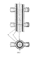
マグネシウム被覆の場合、二重材料(図4参照)から作られたパイプを選ぶことができる。内側はボイラーのための低炭素鋼から作られた非溶接Cチューブにより形成される。実際、このタイプのチューブは完全に適しており、鉄は液体マグネシウムに非常に溶解困難である(数ppmのオーダー)。外側Bはインコネルから作られる。ステンレス鋼は、再溶融される前に低炭素鋼Cチューブ上に溶融により付着される。機械応力を制限するために、非常に固い基準棒(図示せず)が付加されており、溶融炉と蒸発ポットの間の連結を与える。それは同様にチューブに対して膨張し、初期機械応力に反発する。加熱の均一性不足によるチューブのそれぞれの間の小さな温度差のための膨張差を容認することができるように、それぞれのチューブはリラ(lyre)の形に作られている(図1参照)。マグネシウムの場合にこの方法の700℃の温度を達成するための全体の膨張はパイロット設備では65mmより大きく表わされ、リラは数ミリメートルの膨張差に耐えることができただけである。従って、チューブは互いに対して並びにポットに対して及びインコネルフランジ(図示せず)を使用する溶融炉に対して固定された。真空封止は、膨張可能な金属封止の後に黒鉛封止を重ねることにより得られた。 In the case of magnesium coating, a pipe made from a double material (see FIG. 4) can be chosen. The inside is formed by a non-welded C tube made from low carbon steel for boilers. In fact, this type of tube is perfectly suitable and iron is very difficult to dissolve in liquid magnesium (on the order of a few ppm). Outer B is made from Inconel. The stainless steel is deposited by melting on the low carbon steel C tube before being remelted. To limit the mechanical stress, a very hard reference rod (not shown) is added to provide a connection between the melting furnace and the evaporation pot. It likewise expands against the tube and repels the initial mechanical stress. Each tube is made in the form of a lyre (see FIG. 1) so that differential expansion due to small temperature differences between each of the tubes due to poor heating uniformity can be tolerated. The overall expansion to achieve a 700 ° C. temperature for this method in the case of magnesium was represented by a pilot installation greater than 65 mm, and the lira could only withstand a few millimeters of expansion differential. Accordingly, the tubes were fixed to each other and to the pot and to the melting furnace using an Inconel flange (not shown). The vacuum seal was obtained by overlaying a graphite seal after an expandable metal seal.
最後に、さらに安全上の理由のため、チューブはベローズの形の第二金属囲いA内に置かれた(図4参照)。あまり強くない第二囲いは、各始動時にチューブの封止を試験することを可能にし、設備を空にしかつそれを留めるために必要な時間の間、チューブの破壊または漏れの際の一時的液溜めとしての役割をすることができる。亜鉛被覆の場合、相溶性材料がまた、二重囲い内に含まれるだろうし、そこでは高温の黒鉛のような材料を保護するために保護雰囲気を注入するかまたは真空を作ることが有利に可能である。 Finally, for further safety reasons, the tube was placed in a second metal enclosure A in the form of a bellows (see FIG. 4). A second enclosure that is not very strong makes it possible to test the sealing of the tube at each start-up, and during the time required to empty and fasten the equipment, a temporary liquid in the event of tube breakage or leakage. Can serve as a reservoir. In the case of zinc coating, compatible materials will also be included in the double enclosure, where it is advantageously possible to inject a protective atmosphere or create a vacuum to protect materials such as hot graphite It is.
溶融炉1は、蒸発ポット9の高さより低い高さに位置される。設備内に作られた真空の効果は液体金属をポンプ輸送し、かつ溶融炉1のレベルと異なるレベルに第二自由表面を発生するだろう。これは、溶融炉1の高さとは異なる高さに位置した蒸発表面となる。この高さの差は二つの主要な特徴に依存する:金属の密度(これはまた、その温度に依存する)、及び大気圧。パイプ8内の弁7がたとえ完全に封止されていなくても、重力単独で真空下の設備の充填を防ぐだろう。
The
以下は、1000mbarの大気圧に対してこれを説明可能にする幾つかの数字である。1barの圧力に対するマノメーターヘッドは、金属の密度により割った10.33に等しい(1bar=10.33m水柱)。
固体マグネシウムの密度:1.74kg/dm3。対応するマノメーターヘッド:5.93m。
660℃での液体マグネシウムの密度:1.59kg/dm3。対応するマノメーターヘッド:6.50m。
700℃での液体マグネシウムの密度:1.56kg/dm3。対応するマノメーターヘッド:6.62m。
固体亜鉛の密度:7.18kg/dm3。対応するマノメーターヘッド:1.44m。
Below are some numbers that make this accountable for an atmospheric pressure of 1000 mbar. The manometer head for a pressure of 1 bar is equal to 10.33 divided by the density of the metal (1 bar = 10.33 m water column).
Solid magnesium density: 1.74 kg / dm 3 . Corresponding manometer head: 5.93 m.
Liquid magnesium density at 660 ° C .: 1.59 kg / dm 3 . Corresponding manometer head: 6.50 m.
Liquid magnesium density at 700 ° C .: 1.56 kg / dm 3 . Corresponding manometer head: 6.62 m.
Solid zinc density: 7.18 kg / dm 3 . Corresponding manometer head: 1.44 m.
従って、一つの金属から次の金属で、自由表面間の高さ、従って装置の高さは非常に異なりうることがわかる。即ち、亜鉛とマグネシウムの間で4.5倍である。 Thus, it can be seen that from one metal to the next, the height between the free surfaces and thus the height of the device can be very different. That is, 4.5 times between zinc and magnesium.
この方法のために選ばれた温度の関数として、高さもまた、例えば660℃と700℃のマグネシウムに対し例えば数十ミリメートルでかなり変わりうることがわかる。 It can be seen that as a function of the temperature chosen for this method, the height can also vary considerably, for example several tens of millimeters, for example for 660 ° C. and 700 ° C. magnesium.
大気圧はまた強い影響を持つ。なぜならそれは、真空が絶対的に残りながら溶融炉の自由表面上に及ぼされる力を表わすからである。50mbarの大気圧の変動は全く普通であり、亜鉛の場合に蒸発ポット内またはパイプ内の高さの70mmより大きい差、マグネシウムの場合に300mmより大きい差を起こすことができる。 Atmospheric pressure also has a strong effect. This is because it represents the force exerted on the free surface of the melting furnace while the vacuum remains absolutely. Variations in atmospheric pressure of 50 mbar are quite common and can cause a difference of more than 70 mm in height in the evaporation pot or pipe in the case of zinc and more than 300 mm in the case of magnesium.
本発明によれば、そのとき、大気圧にかかわらず、真空により発生された低い圧力が蒸発ポットを充填しないような高さに位置された蒸発ポットを使用する選択がなされる。真空が作られるとき、有利には、溶融金属は、蒸発ポット9の下に数十センチメートルに位置したレベルまで供給パイプ8及び戻り18,8Aパイプ内で上昇できるのみである。次いで最適な状態下の金属の蒸発を確保するのに必要な予め決められたレベルまで蒸発ポット9を充填するのは、供給ポンプ6により発生された圧力である。この原理は、本発明による設備に対する安全の強い意向を付加する。実際に、もし真空が高温の液体金属の有意な量(典型的には数百kg)の高さを維持するために本質的に十分であったなら、ポットまたはパイプの破壊の危険は、金属が溶融炉1に向けて戻るよう強制されない限り液体金属の有意な量の低下を作りうる。
According to the invention, then a choice is made to use an evaporation pot positioned at a height such that the low pressure generated by the vacuum does not fill the evaporation pot, regardless of atmospheric pressure. When a vacuum is created, advantageously, the molten metal can only rise in the supply pipe 8 and the
ここで、供給ポンプ6を停止することまたは弁を開くことは、蒸発ポット9を空にすることを作り、レベルは低い圧力により発生されたそのマノメーターヘッドに自動的に戻る。液体金属はそのときパイプ内に残るにすぎず、それはほんの数リットルを示す。
Here, stopping the
本発明による設備は、最後に、パイプ8,8A,18内に決定されかつ強化された領域7,13,15を含み、パイプを破壊することなくマグネシウムを溶融可能にする。このパイプ部分のために選ばれた合金は、高圧及び高温に適している。「加熱弁(heat valve)」と呼ばれるこの領域は、強力な加熱装置及び迅速な冷却装置を備えており、他の領域(溶融炉、蒸発ポット及び液体金属パイプの残りの部分)から独立して、希望の温度を管理可能にするように調節される。従って、その領域内の金属を凝固及び溶融可能にする。
The installation according to the invention finally comprises the determined and strengthened
本発明によれば、加熱弁は、二重囲いから作られることができ、冷却はそのとき二重囲い(図示せず)内の冷たい空気の注入及び循環により起こる。 According to the invention, the heating valve can be made from a double enclosure, and cooling then takes place by the injection and circulation of cold air in a double enclosure (not shown).
本発明によれば、この設備を保護する固体金属プラグがこのようにして作られることができる。比較的低い温度が維持されることもでき、蒸発を防止または制限する。従って、パイプ内の蒸発またはその中の金属の上昇なしに溶融炉及びその上の真空を持たせることが可能である。従って、二つの製造操業間で、設備の残りを真空下に維持及び/または加熱させることなしに溶融状態の金属を含む溶融炉を維持することが可能である。パイプ内に液体金属がもはや存在せず、決して凝固されないので、パイプはもし必要なら分解されることができる。 According to the invention, a solid metal plug that protects this installation can be made in this way. A relatively low temperature can also be maintained, preventing or limiting evaporation. It is therefore possible to have a melting furnace and a vacuum above it without evaporation in the pipe or rise of the metal therein. It is thus possible to maintain a melting furnace containing molten metal between the two production operations without having to maintain and / or heat the rest of the equipment under vacuum. Since the liquid metal no longer exists in the pipe and is never solidified, the pipe can be disassembled if necessary.
本発明による設備はさらに、次の装置を単独または組み合わせて備えることができる(図2及び3):
− 一次蒸気弁19に加えて、蒸着囲い内に真空を持たせながら封止を与えかつポット内に大気圧を持たせることを可能にする二次蒸気弁22,23;
− 不活性ガスを蒸発ポット9中に送り、従ってマグネシウム11を溶融炉の方に押し戻すことを可能にするアルゴン分配キャビネット37;
− 蒸発ポットの底の保持区画室43、または一次蒸気パイプ上にあるが一次弁19の前の余分なポット44、前記ポットは、液体金属の供給パイプ及び戻りパイプ内での蒸発のために十分な圧力の金属蒸気を発生するために必要な出力を局所化された態様で発生させることを可能にする加熱手段(図示せず)を備え、それらのパイプ中の液体金属の凝固から始まる。区画室43は、有利にはポットの誘導手段42によりまたはいずれかの他の好適な装置により加熱されることができる。
The installation according to the invention can further comprise the following devices alone or in combination (FIGS. 2 and 3):
In addition to the
An
A holding
装置のこれらの種々の部分により、始動サイクルは次の通りである:
− 金属の溶融は、真空を作ったりまたはパイプ及び設備の残りをあらかじめ加熱する必要なしに炉内で始動される;
− 金属はそれぞれの加熱弁7,13,15内で固体状態に保たれ、従って低温に保たれる;
− 設備が準備され、すなわち排気されかつ液体金属及び/または蒸気を受ける温度にあるとき、蒸気パイプ上の分配弁は閉じられ、金属蒸気が、液体金属がパイプ及びポット内でポットの出口のパイプ上の追加のポット44または蒸気ポットの底の保持区画室43を通して持つであろう温度より高い温度で発生される。この蒸気は、蒸発ポット9及びパイプを満たし、加熱弁7,13,15内または真空により発生された低い圧力の影響下でパイプ内を上昇する液体の表面上での蒸発を防ぐだろう。例えば、マグネシウムに対しては、液体は685〜690℃の温度にもたらされるだろうし、蒸気は保持区画室43または余分なポット44から出発して700℃で発生されるだろう。上昇する傾向がある液体に対しては、雰囲気は既に飽和され、いかなる蒸発も不可能である。
With these various parts of the device, the start-up cycle is as follows:
-Melting of the metal is initiated in the furnace without the need to create a vacuum or preheat the rest of the pipes and equipment;
The metal is kept in a solid state in each
The distribution valve on the steam pipe is closed when the equipment is ready, i.e. evacuated and at a temperature to receive liquid metal and / or steam, the metal steam is in the pipe and in the pot and the pipe at the outlet of the pot It is generated at a temperature above that which would have through the
そのとき低温の加熱弁7,13,15の調節を停止しかつそこに見出される金属をそれを炉の温度にもたらすことにより溶融することも可能である。いったんそれが溶融されたら、金属はパイプ内の低い圧力の影響下で上昇するだろう。発生される金属蒸気による蒸発ポット9内の圧力は数mbarであるだろうし、パイプの容積に対して大きい蒸発ポットの容積は、金属の上昇にもかかわらずその圧力を保つことを可能にする。蒸発ポットは、次いで供給ポンプ6及び戻り弁14及び溶融炉1中の他のものに作用することにより満たされることができる。本発明の好適な実施態様によれば、溶融炉1が充満しておりかつ蒸発ポット9が空であるときに溶融炉1内の液体金属と同じレベル高さは例えば加熱弁7,13,15の位置として選ばれる。これは第一始動を容易にするが、いかなる他の位置も本発明の適用範囲内である。
It is then also possible to melt by stopping the adjustment of the
設備を空にするために、次の操作が実施される:
− 蒸気パイプ上の弁19が閉じられる;
− 供給ポンプ6が停止され、パイプ8,18上の弁14,17が開かれる;
− 液体金属がアルゴン圧により溶融炉の方に押し戻される。アルゴン流は、初めに、加熱弁7,13,15内の金属を正確に正しい高さで停止するように、溶融炉上に及ぼされる大気圧に等しい圧力を維持するために流速を調節する前に大気圧に近い圧力まで管理される;
− 状態の適切な平衡を確保することを可能にする長さの時間の後に、加熱弁の加熱は停止されることができ、それらの冷却はそれらのまさに内側の金属を凝固するように確保されることができる。従って、ポット側では、自由表面は冷たくかつ不活性である;
− 従って、空になった設備はいかなる危険もなしに停止されることができる。
To empty the equipment, the following operations are performed:
The
The
The liquid metal is pushed back towards the melting furnace by argon pressure. The argon flow is initially adjusted before the flow rate is adjusted to maintain a pressure equal to the atmospheric pressure exerted on the melting furnace so that the metal in the
-After a length of time that makes it possible to ensure a proper balance of the conditions, the heating of the heating valves can be stopped and their cooling is ensured to solidify their very inner metal. Can. Thus, on the pot side, the free surface is cold and inert;
-The emptied equipment can therefore be shut down without any danger.
加熱弁内の「凍結」プラグを持つ位置は安全位置と呼ばれる。設備内で観察される異常及び深刻になりうる異常もその位置への強制的な戻り(例えば加熱要素の破壊)を自動的に発生する。 The position with the “frozen” plug in the heating valve is called the safe position. Anomalies observed in the facility and anomalies that can become serious also automatically generate a forced return to that position (eg, destruction of the heating element).
ポット内に位置されるアルゴンは、もし装置が再始動されなければならないならポット内の適切な真空レベルを回復するように徐々に真空ポンプ輸送設備に向けて放出されることができる。さもなければ、アルゴンはポット内に残され、液体パイプ、蒸発ポット及び加熱弁内の金属の自由表面の酸化を遅らせる保護クッションを構成する。 Argon located in the pot can be gradually released towards the vacuum pumping facility to restore the proper vacuum level in the pot if the device must be restarted. Otherwise, argon is left in the pot and constitutes a protective cushion that delays oxidation of the free surface of the metal in the liquid pipe, evaporation pot and heating valve.
1:溶融炉
2:溶融炉内のマグネシウム
3:供給弁
4,5:供給弁制御
6:供給ポンプ
7:供給加熱弁
8:ポットの供給パイプ
8A:溢流パイプ
9:ポットの本体(誘導加熱された)
10:ポットのドーム及び蒸気溜め(輻射加熱された)
11:ポット内のマグネシウム
13:溢流加熱弁
14:戻り弁
15:再循環加熱弁
16:溢流弁
17:戻り弁
18:再循環パイプ
19:一次蒸気分配弁
20:一次蒸気供給パイプ
21:二次蒸気供給弁
22及び23:蒸気流速調節弁
24:蒸着囲い
25,26:被覆ヘッド
27,28:蒸着区画室
29:高レベル探針
30:低レベル探針
31:インゴット供給器(加熱T1を持つ)
32:インゴット分配弁
33:貯蔵インゴット
34:炉内で溶融を受けるインゴット
35:低レベル加熱
36:高レベル加熱
37:アルゴン分配キャビネット
38:アルゴン分配弁
39,40,41:ポットのためのレベル探針
42:金属の蒸発のための加熱誘導器
43:蒸発ポットの底の保持区画室
44:蒸気を発生するための余分なポット
A:ベローズの形の金属囲い
B:抵抗性ステンレス鋼被覆
C:低炭素鋼から作られた非溶接チューブ
1: Melting furnace 2: Magnesium in melting furnace 3: Feed valve 4, 5: Feed valve control 6: Feed pump 7: Feed heating valve 8:
10: Pot dome and steam reservoir (radiant heated)
11: Magnesium in the pot 13: Overflow heating valve 14: Return valve 15: Recirculation heating valve 16: Overflow valve 17: Return valve 18: Recirculation pipe 19: Primary steam distribution valve 20: Primary steam supply pipe 21: Secondary
32: Ingot distribution valve 33: Storage ingot 34: Ingot subjected to melting in the furnace 35: Low level heating 36: High level heating 37: Argon distribution cabinet 38:
Claims (14)
− 炉(1)内の金属の溶融が、供給パイプ及び戻りパイプ(8,8A,18)の加熱弁(7,13,15)内の一部の金属を固体状態に保ちながら、始動される;
− 前記設備の残りが、液体金属及び/または金属蒸気を受けるために必要な温度に加熱され、供給パイプ(20)の分配弁(19)が閉じられ、かつ蒸着囲い(24)が真空下に置かれる;
− 前記液体金属保持装置(43)が、蒸着時の設備内の液体金属の温度より高い温度に活性化される;
− 加熱弁(7,13,15)内に含まれる凝固金属が溶融される;
− 蒸発ポット(9)が次いで供給ポンプ(6)を使用して満たされ、供給パイプ(20)の分配弁(19)が開かれ、かつ移動中の前記基板上の金属の蒸着が始まる;ことを特徴とする方法。 A method for starting an installation as claimed in claim 2 , according to which:
-The melting of the metal in the furnace (1) is started while keeping some of the metal in the heating valves (7, 13, 15) of the supply and return pipes (8 , 8A, 18) in a solid state. ;
The remainder of the equipment is heated to the temperature required to receive liquid metal and / or metal vapor, the distribution valve (19) of the supply pipe (20) is closed and the deposition enclosure (24) is under vacuum Placed;
The liquid metal holding device (43) is activated to a temperature higher than the temperature of the liquid metal in the equipment during the deposition;
The solidified metal contained in the heating valve (7, 13, 15) is melted;
The evaporation pot (9) is then filled using the supply pump (6), the distribution valve (19) of the supply pipe (20) is opened and the deposition of metal on the moving substrate begins ; A method characterized by .
− 炉(1)内の金属の溶融が、供給パイプ及び戻りパイプ(8,8A,18)の加熱弁(7,13,15)内の一部の金属を固体状態に保ちながら、始動される;
− 前記設備の残りが、液体金属及び/または金属蒸気を受けるために必要な温度に加熱され、供給パイプ(20)の分配弁(19)が閉じられ、かつ蒸着囲い(24)が真空下に置かれる;
− 前記余分のポット(44)が、蒸着時の設備内の液体金属の温度より高い温度に活性化される;
− 加熱弁(7,13,15)内に含まれる凝固金属が溶融される;
− 蒸発ポット(9)が次いで供給ポンプ(6)を使用して満たされ、供給パイプ(20)の分配弁(19)が開かれ、かつ移動中の前記基板上の金属の蒸着が始まる;ことを特徴とする方法。 A method for starting an installation as claimed in claim 3 , according to which:
-The melting of the metal in the furnace (1) is started while keeping some of the metal in the heating valves (7, 13, 15) of the supply and return pipes (8 , 8A, 18) in a solid state. ;
The remainder of the equipment is heated to the temperature required to receive liquid metal and / or metal vapor, the distribution valve (19) of the supply pipe (20) is closed and the deposition enclosure (24) is under vacuum Placed;
The extra pot (44) is activated to a temperature higher than the temperature of the liquid metal in the equipment during the deposition;
The solidified metal contained in the heating valve (7, 13, 15) is melted;
The evaporation pot (9) is then filled using the supply pump (6), the distribution valve (19) of the supply pipe (20) is opened and the deposition of metal on the moving substrate begins ; A method characterized by.
Applications Claiming Priority (3)
| Application Number | Priority Date | Filing Date | Title |
|---|---|---|---|
| EP11151004 | 2011-01-14 | ||
| EP11151004.6 | 2011-01-14 | ||
| PCT/EP2012/050432 WO2012095489A1 (en) | 2011-01-14 | 2012-01-12 | Automatic feeding device for an industrial metal-vapor generator |
Publications (3)
| Publication Number | Publication Date |
|---|---|
| JP2014505794A JP2014505794A (en) | 2014-03-06 |
| JP2014505794A5 JP2014505794A5 (en) | 2014-11-27 |
| JP6046051B2 true JP6046051B2 (en) | 2016-12-14 |
Family
ID=43711015
Family Applications (1)
| Application Number | Title | Priority Date | Filing Date |
|---|---|---|---|
| JP2013548844A Active JP6046051B2 (en) | 2011-01-14 | 2012-01-12 | Automatic feeder for industrial metal steam generators. |
Country Status (17)
| Country | Link |
|---|---|
| US (1) | US10011905B2 (en) |
| EP (1) | EP2663665B1 (en) |
| JP (1) | JP6046051B2 (en) |
| KR (1) | KR101786160B1 (en) |
| CN (1) | CN103328680B (en) |
| AU (1) | AU2012206581B2 (en) |
| BR (1) | BR112013018030B1 (en) |
| CA (1) | CA2824248C (en) |
| ES (1) | ES2538661T3 (en) |
| HU (1) | HUE026398T2 (en) |
| IN (1) | IN2013DN06279A (en) |
| MX (1) | MX342299B (en) |
| PL (1) | PL2663665T3 (en) |
| RU (1) | RU2584369C2 (en) |
| UA (1) | UA111602C2 (en) |
| WO (1) | WO2012095489A1 (en) |
| ZA (1) | ZA201305032B (en) |
Families Citing this family (12)
| Publication number | Priority date | Publication date | Assignee | Title |
|---|---|---|---|---|
| KR101461738B1 (en) * | 2012-12-21 | 2014-11-14 | 주식회사 포스코 | Apparatus for heating materials and coatting system having the same |
| US9240584B1 (en) | 2012-12-27 | 2016-01-19 | Sakti3, Inc. | Phase change material source for physical vapor deposition |
| EP3066229B1 (en) * | 2013-11-05 | 2020-08-26 | Tata Steel Nederland Technology B.V. | Method for controlling the composition of liquid metal in an evaporator device |
| US11220739B2 (en) * | 2016-05-03 | 2022-01-11 | Tata Steel Nederland Technology B.V. | Apparatus for feeding a liquid material to an evaporator device |
| WO2018020296A1 (en) | 2016-07-27 | 2018-02-01 | Arcelormittal | Apparatus and method for vacuum deposition |
| EP3735996B1 (en) * | 2019-05-07 | 2023-09-27 | Free Life Medical GmbH | Bi-directional perfusion cannula |
| CN112505286B (en) * | 2019-09-16 | 2023-08-11 | 中国科学院上海光学精密机械研究所 | Detection device and method for zinc-induced liquid metal crack formation condition |
| CN113930738B (en) * | 2020-06-29 | 2023-09-12 | 宝山钢铁股份有限公司 | Metal vapor modulation device for vacuum coating and modulation method thereof |
| CN113957389B (en) * | 2020-07-21 | 2023-08-11 | 宝山钢铁股份有限公司 | Vacuum coating device with porous noise reduction and uniform distribution of metal vapor |
| US20220090256A1 (en) * | 2020-09-18 | 2022-03-24 | Applied Materials, Inc. | Evaporation apparatus, vapor deposition apparatus, and evaporation method |
| CN114029001B (en) * | 2021-12-03 | 2023-11-24 | 上海镁源动力科技有限公司 | Device and method for automatically feeding liquid metal raw materials |
| EP4446459A1 (en) * | 2023-04-11 | 2024-10-16 | NEOVAC GmbH | Evaporation crucible and evaporation unit |
Family Cites Families (8)
| Publication number | Priority date | Publication date | Assignee | Title |
|---|---|---|---|---|
| SU1505064A2 (en) * | 1987-08-04 | 1994-12-15 | Специализированное конструкторско-технологическое бюро с опытным производством Института электроники им.У.А.Арифова | Electric-arc evaporator |
| US5356673A (en) * | 1991-03-18 | 1994-10-18 | Jet Process Corporation | Evaporation system and method for gas jet deposition of thin film materials |
| BE1010351A6 (en) | 1996-06-13 | 1998-06-02 | Centre Rech Metallurgique | Method and device for coating continuous substrate in motion with a metal vapor. |
| JP3901773B2 (en) * | 1996-11-26 | 2007-04-04 | 三菱重工業株式会社 | Vacuum deposition equipment |
| LV13383B (en) * | 2004-05-27 | 2006-02-20 | Sidrabe As | Method and device for vacuum vaporization metals or alloys |
| EP1972699A1 (en) * | 2007-03-20 | 2008-09-24 | ArcelorMittal France | Method of coating a substrate under vacuum |
| EP2048261A1 (en) | 2007-10-12 | 2009-04-15 | ArcelorMittal France | Industrial steam generator for depositing an alloy coating on a metal band |
| EP2199425A1 (en) * | 2008-12-18 | 2010-06-23 | ArcelorMittal France | Industrial steam generator for depositing any alloy coating on a metal band (II) |
-
2012
- 2012-01-12 PL PL12700188T patent/PL2663665T3/en unknown
- 2012-01-12 WO PCT/EP2012/050432 patent/WO2012095489A1/en active Application Filing
- 2012-01-12 US US13/979,598 patent/US10011905B2/en active Active
- 2012-01-12 RU RU2013137228/02A patent/RU2584369C2/en active
- 2012-01-12 BR BR112013018030-7A patent/BR112013018030B1/en active IP Right Grant
- 2012-01-12 ES ES12700188.1T patent/ES2538661T3/en active Active
- 2012-01-12 EP EP12700188.1A patent/EP2663665B1/en active Active
- 2012-01-12 CA CA2824248A patent/CA2824248C/en active Active
- 2012-01-12 AU AU2012206581A patent/AU2012206581B2/en active Active
- 2012-01-12 CN CN201280005167.6A patent/CN103328680B/en active Active
- 2012-01-12 KR KR1020137021413A patent/KR101786160B1/en active IP Right Grant
- 2012-01-12 JP JP2013548844A patent/JP6046051B2/en active Active
- 2012-01-12 IN IN6279DEN2013 patent/IN2013DN06279A/en unknown
- 2012-01-12 HU HUE12700188A patent/HUE026398T2/en unknown
- 2012-01-12 MX MX2013008174A patent/MX342299B/en active IP Right Grant
- 2012-12-01 UA UAA201310074A patent/UA111602C2/en unknown
-
2013
- 2013-07-04 ZA ZA2013/05032A patent/ZA201305032B/en unknown
Also Published As
| Publication number | Publication date |
|---|---|
| JP2014505794A (en) | 2014-03-06 |
| WO2012095489A1 (en) | 2012-07-19 |
| UA111602C2 (en) | 2016-05-25 |
| ES2538661T3 (en) | 2015-06-23 |
| CN103328680B (en) | 2015-05-20 |
| KR20140041436A (en) | 2014-04-04 |
| ZA201305032B (en) | 2014-07-30 |
| HUE026398T2 (en) | 2016-06-28 |
| BR112013018030A2 (en) | 2020-10-27 |
| US20140127406A1 (en) | 2014-05-08 |
| MX2013008174A (en) | 2013-12-02 |
| RU2013137228A (en) | 2015-02-20 |
| CA2824248A1 (en) | 2012-07-19 |
| RU2584369C2 (en) | 2016-05-20 |
| IN2013DN06279A (en) | 2015-08-14 |
| EP2663665B1 (en) | 2015-03-11 |
| CN103328680A (en) | 2013-09-25 |
| EP2663665A1 (en) | 2013-11-20 |
| US10011905B2 (en) | 2018-07-03 |
| PL2663665T3 (en) | 2015-08-31 |
| CA2824248C (en) | 2019-11-05 |
| AU2012206581B2 (en) | 2017-03-30 |
| KR101786160B1 (en) | 2017-10-17 |
| MX342299B (en) | 2016-09-23 |
| BR112013018030B1 (en) | 2021-05-18 |
Similar Documents
| Publication | Publication Date | Title |
|---|---|---|
| JP6046051B2 (en) | Automatic feeder for industrial metal steam generators. | |
| JP6313746B2 (en) | Method and apparatus for supplying liquid metal to an evaporator | |
| JP2008500454A (en) | Vacuum deposition method and apparatus by evaporation of metal and alloy | |
| JP7182466B2 (en) | Method for operating a device for supplying liquid metal to an evaporator | |
| WO2010030331A1 (en) | Method and apparatus for sealing an ingot at initial startup | |
| KR101713112B1 (en) | Deposition material supply apparatus which can continuously charged | |
| US20140041414A1 (en) | Remote Cool Down of a Purified Directionally Solidified Material From an Open Bottom Cold Crucible Induction Furnace | |
| KR0173457B1 (en) | Method and apparatus for continuously discharging molten metal and slag | |
| JP2008161875A (en) | Casting nozzle suitable for achieving cast product having excellent surface property, method for manufacturing cast product using the same, and magnesium alloy | |
| TWI402215B (en) | Molten evaporation device of metals | |
| AU2017260147B2 (en) | Apparatus for feeding a liquid material to an evaporator device | |
| US6819704B2 (en) | Induction melting furnace with metered discharge | |
| KR20070015923A (en) | Method and apparatus for vacuum deposition by vaporizing metals and metal alloys | |
| WO2003048398A1 (en) | Method of and apparatus for condensing metallic vapours | |
| WO2010143417A1 (en) | Silicon melt transfer member and silicon melt transfer method | |
| JP2794655B2 (en) | Pressurized pouring furnace | |
| JPH09164476A (en) | Apparatus for distribution of magnesium or magnesium alloy | |
| JP2010099666A (en) | Molten metal distribution method in molten metal retaining furnace for casting | |
| RU2244030C1 (en) | Vacuum arc furnace | |
| KR100735094B1 (en) | The mixing-device for molten-metal of thermostat-solution system it uses the electromagnetic pump, and The mixing-system | |
| JP2006179711A (en) | Heating method and heating apparatus | |
| JPH09137268A (en) | Method for evaporating magnesium |
Legal Events
| Date | Code | Title | Description |
|---|---|---|---|
| A521 | Request for written amendment filed |
Free format text: JAPANESE INTERMEDIATE CODE: A523 Effective date: 20141007 |
|
| A621 | Written request for application examination |
Free format text: JAPANESE INTERMEDIATE CODE: A621 Effective date: 20141007 |
|
| A977 | Report on retrieval |
Free format text: JAPANESE INTERMEDIATE CODE: A971007 Effective date: 20150710 |
|
| A131 | Notification of reasons for refusal |
Free format text: JAPANESE INTERMEDIATE CODE: A131 Effective date: 20150717 |
|
| A601 | Written request for extension of time |
Free format text: JAPANESE INTERMEDIATE CODE: A601 Effective date: 20151014 |
|
| A521 | Request for written amendment filed |
Free format text: JAPANESE INTERMEDIATE CODE: A523 Effective date: 20160115 |
|
| A131 | Notification of reasons for refusal |
Free format text: JAPANESE INTERMEDIATE CODE: A131 Effective date: 20160603 |
|
| TRDD | Decision of grant or rejection written | ||
| A01 | Written decision to grant a patent or to grant a registration (utility model) |
Free format text: JAPANESE INTERMEDIATE CODE: A01 Effective date: 20161021 |
|
| A61 | First payment of annual fees (during grant procedure) |
Free format text: JAPANESE INTERMEDIATE CODE: A61 Effective date: 20161116 |
|
| R150 | Certificate of patent or registration of utility model |
Ref document number: 6046051 Country of ref document: JP Free format text: JAPANESE INTERMEDIATE CODE: R150 |
|
| R250 | Receipt of annual fees |
Free format text: JAPANESE INTERMEDIATE CODE: R250 |
|
| R250 | Receipt of annual fees |
Free format text: JAPANESE INTERMEDIATE CODE: R250 |
|
| R250 | Receipt of annual fees |
Free format text: JAPANESE INTERMEDIATE CODE: R250 |
|
| R250 | Receipt of annual fees |
Free format text: JAPANESE INTERMEDIATE CODE: R250 |
|
| R250 | Receipt of annual fees |
Free format text: JAPANESE INTERMEDIATE CODE: R250 |