JP6045924B2 - Touch panel display device and touch panel controller - Google Patents
Touch panel display device and touch panel controller Download PDFInfo
- Publication number
- JP6045924B2 JP6045924B2 JP2013012921A JP2013012921A JP6045924B2 JP 6045924 B2 JP6045924 B2 JP 6045924B2 JP 2013012921 A JP2013012921 A JP 2013012921A JP 2013012921 A JP2013012921 A JP 2013012921A JP 6045924 B2 JP6045924 B2 JP 6045924B2
- Authority
- JP
- Japan
- Prior art keywords
- detection
- touch panel
- touch
- drive
- panel display
- Prior art date
- Legal status (The legal status is an assumption and is not a legal conclusion. Google has not performed a legal analysis and makes no representation as to the accuracy of the status listed.)
- Active
Links
Images


Classifications
-
- G—PHYSICS
- G06—COMPUTING; CALCULATING OR COUNTING
- G06F—ELECTRIC DIGITAL DATA PROCESSING
- G06F3/00—Input arrangements for transferring data to be processed into a form capable of being handled by the computer; Output arrangements for transferring data from processing unit to output unit, e.g. interface arrangements
- G06F3/01—Input arrangements or combined input and output arrangements for interaction between user and computer
- G06F3/03—Arrangements for converting the position or the displacement of a member into a coded form
- G06F3/041—Digitisers, e.g. for touch screens or touch pads, characterised by the transducing means
- G06F3/0416—Control or interface arrangements specially adapted for digitisers
- G06F3/04166—Details of scanning methods, e.g. sampling time, grouping of sub areas or time sharing with display driving
- G06F3/041661—Details of scanning methods, e.g. sampling time, grouping of sub areas or time sharing with display driving using detection at multiple resolutions, e.g. coarse and fine scanning; using detection within a limited area, e.g. object tracking window
-
- G—PHYSICS
- G06—COMPUTING; CALCULATING OR COUNTING
- G06F—ELECTRIC DIGITAL DATA PROCESSING
- G06F3/00—Input arrangements for transferring data to be processed into a form capable of being handled by the computer; Output arrangements for transferring data from processing unit to output unit, e.g. interface arrangements
- G06F3/01—Input arrangements or combined input and output arrangements for interaction between user and computer
- G06F3/03—Arrangements for converting the position or the displacement of a member into a coded form
- G06F3/041—Digitisers, e.g. for touch screens or touch pads, characterised by the transducing means
- G06F3/044—Digitisers, e.g. for touch screens or touch pads, characterised by the transducing means by capacitive means
- G06F3/0446—Digitisers, e.g. for touch screens or touch pads, characterised by the transducing means by capacitive means using a grid-like structure of electrodes in at least two directions, e.g. using row and column electrodes
-
- G—PHYSICS
- G06—COMPUTING; CALCULATING OR COUNTING
- G06F—ELECTRIC DIGITAL DATA PROCESSING
- G06F2203/00—Indexing scheme relating to G06F3/00 - G06F3/048
- G06F2203/048—Indexing scheme relating to G06F3/048
- G06F2203/04809—Textured surface identifying touch areas, e.g. overlay structure for a virtual keyboard
Landscapes
- Engineering & Computer Science (AREA)
- General Engineering & Computer Science (AREA)
- Theoretical Computer Science (AREA)
- Human Computer Interaction (AREA)
- Physics & Mathematics (AREA)
- General Physics & Mathematics (AREA)
- Position Input By Displaying (AREA)
- Push-Button Switches (AREA)
Description
本発明は、表示領域としてタッチパネル表示部を備え且つボタン領域としてタッチキー入力部を備えたタッチパネル表示装置、及びそのようなタッチパネル表示装置に適用可能なタッチパネルコントローラに関し、例えば情報端末などに適用して有効な技術に関する。 The present invention relates to a touch panel display device including a touch panel display unit as a display region and a touch key input unit as a button region, and a touch panel controller applicable to such a touch panel display device. It relates to effective technology.
タブレットやスマートフォンなどの携帯情報端末の表面には表示領域とボタン領域が形成され、特許文献1に例示されるように表示領域には液晶パネルにタッチパネルが重ねて配置され、ボタン領域には複数のボタンが配置される。ユーザは、表示領域に表示された情報に対応する位置に対してタッチパネルを指などで直接操作することができるようになされる。ボタン領域のボタンはタッチパネルの操作から切り離して操作可能にされる。 A display area and a button area are formed on the surface of a portable information terminal such as a tablet or a smartphone. As exemplified in Patent Document 1, a touch panel is arranged on a liquid crystal panel in the display area, and a plurality of buttons are provided in the button area. A button is placed. The user can directly operate the touch panel with a finger or the like at a position corresponding to the information displayed in the display area. The buttons in the button area can be operated separately from the operation of the touch panel.
本発明者はボタン領域のボタンをタッチスイッチのようなタッチセンサで形成したとき、表示領域のタッチパネルに対する駆動及び検出と、ボタン領域のタッチセンサに対する駆動及び検出とを一つのタッチパネルコントローラで制御することについて検討した。 When the inventor forms the buttons in the button area with a touch sensor such as a touch switch, the touch area in the display area is controlled and driven and the touch sensor in the button area is controlled by a single touch panel controller. Was examined.
タッチパネルに対してはマルチタッチ検出を実現するために例えば相互容量方式を採用するが必要であるが、ボタン領域のタッチセンサはオン・オフスイッチ機能が実現されれば十分なことから自己容量検出方式で済む。更にパネルと単体スイッチの違い等から負荷容量も相違する。そのような違いに対してそれぞれに好適な駆動及び検出を行なうタッチパネルコントローラを別々に用いることが可能である。 In order to realize multi-touch detection for the touch panel, it is necessary to adopt the mutual capacitance method, for example, but the touch sensor in the button area is sufficient if the on / off switch function is realized, so the self-capacitance detection method Just do it. Furthermore, the load capacity is also different due to the difference between the panel and the single switch. It is possible to separately use touch panel controllers that perform suitable driving and detection for such differences.
しかしながら、表示用とボタン用に2個のタッチパネルコントローラを別々に用いる場合にはコスト上昇を招くという問題を生ずる。表示用とボタン用に一つのタッチパネルコントローラを用いる場合にはパネルとスイッチとに対する検出特性やその他電気的特性の相違がタッチ検出に悪影響を与えないようにする新たな工夫が必要になる。 However, when two touch panel controllers are used separately for display and buttons, there is a problem that the cost increases. When one touch panel controller is used for the display and the button, a new device is required to prevent a difference in detection characteristics and other electrical characteristics between the panel and the switch from adversely affecting touch detection.
上記並びにその他の課題と新規な特徴は本明細書の記述及び添付図面から明らかになるであろう。 The above and other problems and novel features will become apparent from the description of the specification and the accompanying drawings.
本願において開示される実施の形態のうち代表的ものの概要を簡単に説明すれば下記の通りである。 An outline of representative ones of the embodiments disclosed in the present application will be briefly described as follows.
すなわち、表示用のタッチパネル表示部のディスプレイパネルに重ねられたタッチパネルと、ボタン用のタッチキー入力部のタッチキーのパターンに重ねられたタッチセンサとの双方を駆動してタッチ検出を行なうのに共通のタッチパネルコントローラを用いる。このタッチパネルコントローラに、双方に共通の検出回路の検出特性をタッチパネル表示部からの検出時とタッチキー入力部からの検出時とに応じて切り替え可能な制御回路を採用する。或いは、タッチパネルコントローラに、タッチパネルとタッチセンサとのそれぞれに個別の検出回路を採用して個別に検出パラメータを設定しておけばよい。タッチパネルとタッチセンサとの駆動回路はそれぞれ個別にしても、或いは、タッチパネルの一部の駆動回路をタッチセンサと共通化してもよい。 That is, it is common to perform touch detection by driving both the touch panel superimposed on the display panel of the display touch panel display unit and the touch sensor superimposed on the touch key pattern of the touch key input unit for buttons. The touch panel controller is used. The touch panel controller employs a control circuit capable of switching the detection characteristics of the detection circuit common to both of them according to the detection from the touch panel display unit and the detection from the touch key input unit. Alternatively, the detection parameters may be set individually by adopting separate detection circuits for the touch panel and the touch sensor in the touch panel controller. The drive circuits for the touch panel and the touch sensor may be individually provided, or a part of the drive circuit for the touch panel may be shared with the touch sensor.
本願において開示される実施の形態のうち代表的なものによって得られる効果を簡単に説明すれば下記のとおりである。 The effects obtained by the representative ones of the embodiments disclosed in the present application will be briefly described as follows.
すなわち、表示用とボタン用に共通のタッチパネルコントローラを用いてタッチパネル表示装置のコストを低減することができると共に、タッチパネルとスイッチとしてのタッチセンサとに対する検出特性やその他電気的特性の相違がタッチ検出に悪影響を与えないようにすることができる。 That is, it is possible to reduce the cost of the touch panel display device by using a common touch panel controller for display and buttons, and the difference in detection characteristics and other electrical characteristics between the touch panel and the touch sensor as a switch is used for touch detection. It is possible to prevent adverse effects.
1.実施の形態の概要
先ず、本願において開示される実施の形態について概要を説明する。実施の形態についての概要説明で括弧を付して参照する図面中の参照符号はそれが付された構成要素の概念に含まれるものを例示するに過ぎない。
1. First, an outline of an embodiment disclosed in the present application will be described. Reference numerals in the drawings referred to with parentheses in the outline description of the embodiments merely exemplify what are included in the concept of the components to which the reference numerals are attached.
〔1〕<ボタン領域と表示領域でタッチ検出特性を切り替える>
タッチパネル表示装置(1A、図3)は、タッチパネル表示部(3)と、タッチキー入力部(4)と、前記タッチパネル表示部及び前記タッチキー入力部を駆動してタッチ検出を行なうタッチパネルコントローラ(6)と、を有する。前記タッチパネル表示部は、相互に重ねて配置された、ドットマトリクス型のディスプレイパネル(10)と、複数の第1駆動電極(20)と複数の第1検出電極(21)との交差部に交差容量(22)がマトリクス状に形成されたタッチパネル(11)とを有する。前記タッチキー入力部は、相互に重ねて配置された、タッチキーのパターン(12)と、第2駆動電極(30)と第2検出電極(31)との交差部に交差容量(32)を持つタッチセンサ(13)とを有する。前記タッチパネルコントローラは、前記第1駆動電極及び第2駆動電極に個別に接続される駆動端子(40,41)と、前記第1検出電極に個別に接続されると共に一部が前記第2検出電極に共通接続される検出端子(50,51)と、所定の順番で前記駆動端子に駆動電圧を与える駆動回路(60)と、前記駆動端子の駆動に同期して前記複数の検出端子に現れる電位変化によって検出信号を形成する検出回路(70)と、前記検出回路の検出特性を前記タッチパネル表示部からの検出時と前記タッチキー入力部からの検出時とに応じて切り替え可能な制御回路(90)とを有する。
[1] <Switching touch detection characteristics between button area and display area>
The touch panel display device (1A, FIG. 3) includes a touch panel display unit (3), a touch key input unit (4), and a touch panel controller (6) that performs touch detection by driving the touch panel display unit and the touch key input unit. And). The touch panel display unit intersects the intersection of the dot matrix type display panel (10), the plurality of first drive electrodes (20), and the plurality of first detection electrodes (21), which are arranged to overlap each other. The touch panel (11) has a capacitor (22) formed in a matrix. The touch key input unit includes a cross capacitor (32) at an intersection of the touch key pattern (12), the second drive electrode (30), and the second detection electrode (31), which are arranged to overlap each other. And a touch sensor (13). The touch panel controller includes a drive terminal (40, 41) individually connected to the first drive electrode and the second drive electrode, a separate connection to the first detection electrode, and a part of the second detection electrode. Detection terminals (50, 51) connected in common to each other, a drive circuit (60) for applying a drive voltage to the drive terminals in a predetermined order, and potentials appearing at the plurality of detection terminals in synchronization with the drive of the drive terminals A detection circuit (70) that forms a detection signal according to a change, and a control circuit (90) that can switch detection characteristics of the detection circuit according to detection from the touch panel display unit and detection from the touch key input unit. ).
これによれば、表示用とボタン用に共通のタッチパネルコントローラを用いてタッチパネル表示装置のコストを低減することができると共に、検出特性の切り替え制御によりタッチパネルとスイッチとしてのタッチセンサとに対する検出特性の相違がタッチ検出に悪影響を与えないようにすることができる。 According to this, it is possible to reduce the cost of the touch panel display device by using a common touch panel controller for display and buttons, and to detect the difference in detection characteristics between the touch panel and the touch sensor as a switch by switching detection characteristics. Does not adversely affect touch detection.
〔2〕<キャリブレーションデータによる検出特性の切り替え>
項1において、前記検出回路は前記検出端子に現れる電位変化に重畳されるオフセット成分をキャリブレーションデータに基づいてキャンセルするキャリブレーション回路(101)を有する。前記制御回路は、前記タッチパネル表示部からの検出時と前記タッチキー入力部からの検出時とに応じて前記キャリブレーションデータを切り替える。
[2] <Switching detection characteristics based on calibration data>
In item 1, the detection circuit includes a calibration circuit (101) that cancels an offset component superimposed on a potential change appearing at the detection terminal based on calibration data. The control circuit switches the calibration data according to detection from the touch panel display unit and detection from the touch key input unit.
これによれば、キャリブレーションデータの切り替えによって簡単に検出特性の切り替えを行う事ができる。 According to this, detection characteristics can be easily switched by switching calibration data.
〔3〕<レジスタ回路のキャリブレーションデータの選択>
項2において、前記制御回路は、書き換え可能にキャリブレーションデータを保持するレジスタ回路と、前記タッチパネル表示部からの検出時と前記タッチキー入力部からの検出時とに応じてレジスタ回路(203,204)からキャリブレーション回路に供給するキャリブレーションデータを選択する選択回路(206)とを有する。
[3] <Selection of register circuit calibration data>
In
これによれば、キャリブレーションデータの切り替えを容易に行う事ができる。 According to this, it is possible to easily switch the calibration data.
〔4〕<積分回路の積分容量値による検出特性の切り替え>
項1又は2において、前記検出回路は前記検出端子に現れる電位変化を積分する積分回路(100)を有する。前記制御回路は、前記タッチパネル表示部からの検出時と前記タッチキー入力部からの検出時とに応じて前記積分回路の積分容量値を切り替える。
[4] <Switching detection characteristics based on integration capacitance value of integration circuit>
In
これによれば、積分回路の積分容量値の切り替えによって簡単に検出特性の切り替えを行う事ができる。 According to this, the detection characteristics can be easily switched by switching the integration capacitance value of the integration circuit.
〔5〕<レジスタ回路の積分容量値指示データの選択>
項4において、前記積分回路は前記電位変化を積分する可変容量素子(102)を有する。前記制御回路は、書き換え可能に前記可変容量素子の積分容量値指示データを保持するレジスタ回路(201,201と、前記タッチパネル表示部からの検出時と前記タッチキー入力部からの検出時とに応じて前記レジスタ回路から前記可変容量素子に供給する積分容量値指示データを選択する選択回路(205)とを有する。
[5] <Selection of integration capacitance value instruction data of register circuit>
In
これによれば、積分容量値の切り替えを容易に行う事ができる。 According to this, the integration capacitance value can be easily switched.
〔6〕<タッチスキャンモードの選択>
項1において、前記制御回路は、前記タッチパネル表示部と前記タッチキー入力部の双方に対応する駆動端子を駆動してタッチ検出動作を行うフルスキャンモード、前記タッチパネル表示部に対応する駆動端子だけを駆動してタッチ検出動作を行う第1パーシャルスキャンモード、又は前記タッチキー入力部に対応する駆動端子だけを駆動してタッチ検出動作を行う第2パーシャルスキャンモードを選択可能にされる。
[6] <Selection of touch scan mode>
In item 1, the control circuit drives a drive terminal corresponding to both the touch panel display unit and the touch key input unit to perform a touch detection operation, and has only a drive terminal corresponding to the touch panel display unit. A first partial scan mode in which a touch detection operation is performed by driving or a second partial scan mode in which only a drive terminal corresponding to the touch key input unit is driven to perform a touch detection operation can be selected.
これによれば、フルスキャンモードにより表示領域としてのタッチパネル表示部とボタン領域としてタッチキー入力部とを併せてタッチ検出を行うことができる。第1パーシャルスキャンモードによりボタン領域としてタッチキー入力部を不使用にする選択が可能になる。第2パーシャルスキャンモードにより、単なる動画表示のようなときに、表示領域からの入力を不可能とする選択を行って低消費電力化を図ることができる。 According to this, it is possible to perform touch detection by combining the touch panel display unit as a display region and the touch key input unit as a button region in the full scan mode. The first partial scan mode makes it possible to select that the touch key input unit is not used as a button area. With the second partial scan mode, it is possible to reduce power consumption by performing selection that disables input from the display area in the case of simple moving image display.
〔7〕<モードレジスタ>
項6において、前記フルスキャンモード、第1パーシャルモード、又は第2パーシャルモードを選択するためのモードデータが書き換え可能に設定されるモードレジスタ(210)を有する。
[7] <Mode register>
これにより、フルスキャンモード、第1パーシャルモード、又は第2パーシャルモードの選択を容易に行うことができる。 Thereby, selection of a full scan mode, a 1st partial mode, or a 2nd partial mode can be performed easily.
〔8〕<ボタン領域と表示領域でタッチ検出特性を切り替えるタッチパネルコントローラ>
タッチパネルコントローラ(6、図3)は、タッチパネル表示部(3)及びタッチキー入力部(4)を駆動してタッチ検出を行なう。前記タッチパネル表示部は、相互に重ねて配置された、ドットマトリクス型のディスプレイパネル(10)と、複数の第1駆動電極(20)と複数の第1検出電極(21)との交差部に交差容量(22)がマトリクス状に形成されたタッチパネル(11)とを有する。前記タッチキー入力部は、相互に重ねて配置された、タッチキーのパターン(12)と、第2駆動電極(30)と第2検出電極(31)との交差部に交差容量(32)を持つタッチセンサ(13)とを有する。前記タッチパネルコントローラは、前記第1駆動電極及び第2駆動電極に個別に接続される駆動端子(40,41)と、前記第1検出電極に個別に接続されると共に一部が前記第2検出電極に共通接続される検出端子(50,51)と、所定の順番で前記駆動端子に駆動電圧を与える駆動回路(60)と、前記駆動端子の駆動に同期して前記複数の検出端子に現れる電位変化によって検出信号を形成する検出回路(70)と、前記検出回路の検出特性を前記タッチパネル表示部からの検出時と前記タッチキー入力部からの検出時とに応じて切り替え可能な制御回路(90)とを有する。
[8] <Touch panel controller that switches touch detection characteristics between button area and display area>
The touch panel controller (6, FIG. 3) drives the touch panel display unit (3) and the touch key input unit (4) to perform touch detection. The touch panel display unit intersects the intersection of the dot matrix type display panel (10), the plurality of first drive electrodes (20), and the plurality of first detection electrodes (21), which are arranged to overlap each other. The touch panel (11) has a capacitor (22) formed in a matrix. The touch key input unit includes a cross capacitor (32) at an intersection of the touch key pattern (12), the second drive electrode (30), and the second detection electrode (31), which are arranged to overlap each other. And a touch sensor (13). The touch panel controller includes a drive terminal (40, 41) individually connected to the first drive electrode and the second drive electrode, a separate connection to the first detection electrode, and a part of the second detection electrode. Detection terminals (50, 51) connected in common to each other, a drive circuit (60) for applying a drive voltage to the drive terminals in a predetermined order, and potentials appearing at the plurality of detection terminals in synchronization with the drive of the drive terminals A detection circuit (70) that forms a detection signal according to a change, and a control circuit (90) that can switch detection characteristics of the detection circuit according to detection from the touch panel display unit and detection from the touch key input unit. ).
これによれば、表示用とボタン用に共通のタッチパネルコントローラを用いてタッチパネル表示装置のコスト低減に寄与することができると共に、検出特性の切り替え制御によりタッチパネルとスイッチとしてのタッチセンサとに対する検出特性の相違がタッチ検出に悪影響を与えないようにすることができる。 According to this, it is possible to contribute to the cost reduction of the touch panel display device by using the common touch panel controller for the display and the button, and the detection characteristic of the touch sensor as the touch panel and the switch by the switching control of the detection characteristic. Differences can be prevented from adversely affecting touch detection.
〔9〕<タッチパネル表示部とタッチキー入力部で検出回路を個別化>
タッチパネル表示装置(1B、図10)は、タッチパネル表示部(3)と、タッチキー入力部(4)と、前記タッチパネル表示部及び前記タッチキー入力部を駆動してタッチ検出を行なうタッチパネルコントローラ(6B)と、を有する。前記タッチパネル表示部は、相互に重ねて配置された、ドットマトリクス型のディスプレイパネル(10)と、複数の第1駆動電極(20)と複数の第1検出電極(21)との交差部に交差容量(22)がマトリクス状に形成されたタッチパネル(11)とを有する。前記タッチキー入力部は、相互に重ねて配置された、タッチキーのパターン(12)と、第2駆動電極(30)と第2検出電極(31)との交差部に交差容量(32)を持つタッチセンサ(13)とを有する。前記タッチパネルコントローラは、前記第1駆動電極及び第2駆動電極に個別に接続される駆動端子(40,41)と、前記第1検出電極及び第2検出電極に個別に接続される検出端子(50,52)と、所定の順番で前記駆動端子に駆動電圧を与える駆動回路(60)と、前記駆動端子の駆動に同期して前記複数の検出端子に現れる電位変化によって検出信号を形成する検出回路(71,72)と、前記駆動回路及び前記検出回路の動作を制御する制御回路(91)とを有する。
[9] <Individual detection circuit with touch panel display and touch key input>
The touch panel display device (1B, FIG. 10) includes a touch panel display unit (3), a touch key input unit (4), and a touch panel controller (6B) that detects the touch by driving the touch panel display unit and the touch key input unit. And). The touch panel display unit intersects the intersection of the dot matrix type display panel (10), the plurality of first drive electrodes (20), and the plurality of first detection electrodes (21), which are arranged to overlap each other. The touch panel (11) has a capacitor (22) formed in a matrix. The touch key input unit includes a cross capacitor (32) at an intersection of the touch key pattern (12), the second drive electrode (30), and the second detection electrode (31), which are arranged to overlap each other. And a touch sensor (13). The touch panel controller includes a drive terminal (40, 41) individually connected to the first drive electrode and the second drive electrode, and a detection terminal (50) individually connected to the first detection electrode and the second detection electrode. , 52), a drive circuit (60) for applying a drive voltage to the drive terminals in a predetermined order, and a detection circuit for forming detection signals by potential changes appearing at the plurality of detection terminals in synchronization with the drive of the drive terminals (71, 72) and a control circuit (91) for controlling the operation of the drive circuit and the detection circuit.
これによれば、表示用とボタン用に共通のタッチパネルコントローラを用いてタッチパネル表示装置のコストを低減することができると共に、タッチパネルとタッチセンサとのそれぞれに個別の検出回路を採用して個別に検出パラメータを設定しておけばタッチパネルとスイッチとしてのタッチセンサとに対する検出特性の相違がタッチ検出に悪影響を与えないようにすることができる。 According to this, it is possible to reduce the cost of the touch panel display device by using a common touch panel controller for the display and the button, and individually detect the touch panel and the touch sensor by using separate detection circuits. If the parameters are set, the difference in detection characteristics between the touch panel and the touch sensor as a switch can be prevented from adversely affecting touch detection.
〔10〕<第1検出電極用の検出回路と第2検出電極用の検出回路との検出特性の最適化>
項9において、前記第1検出電極に対応する検出端子と接続する検出回路の検出特性と、前記第2検出電極に対応する検出端子と接続する検出回路の検出特性との間に相違を有する。
[10] <Optimization of detection characteristics of detection circuit for first detection electrode and detection circuit for second detection electrode>
In item 9, there is a difference between the detection characteristic of the detection circuit connected to the detection terminal corresponding to the first detection electrode and the detection characteristic of the detection circuit connected to the detection terminal corresponding to the second detection electrode.
これによれば、タッチパネルとタッチセンサとのそれぞれに個別の検出回路に好適な検出特性を予め設定しておくことが可能になる。 According to this, it becomes possible to set beforehand the detection characteristic suitable for an individual detection circuit for each of a touch panel and a touch sensor.
〔11〕<タッチスキャンモードの選択>
項9において、前記制御回路は、前記タッチパネル表示部と前記タッチキー入力部のそれぞれに対応する駆動端子を駆動し且つ前記タッチパネル表示部と前記タッチキー入力部のそれぞれに対応する検出端子からの入力を用いてタッチ検出動作を行うフルスキャンモード、前記タッチパネル表示部に対応する駆動端子を駆動し且つ前記タッチパネル表示部に対応する検出端子からの入力を用いてタッチ検出動作を行う第1パーシャルスキャンモード、又は前記タッチキー入力部に対応する駆動端子を駆動し且つ前記タッチキー入力部に対応する検出端子からの入力を用いてタッチ検出動作を行う第2パーシャルスキャンモードを選択可能にされる。
[11] <Selection of touch scan mode>
In item 9, the control circuit drives drive terminals corresponding to the touch panel display unit and the touch key input unit and inputs from detection terminals corresponding to the touch panel display unit and the touch key input unit, respectively. full scan mode for performing touch detection operation using a first partial performing data pitch detection operation using the input from the detection terminals corresponding to the drives the drive terminal corresponding to the touch panel display unit and the touch panel display unit scan mode, or selectable second partial scan mode for performing data pitch detection operation using the input from the detection terminals corresponding to the driving terminal drives and the touch key input unit corresponding to the touch key input unit Is done.
これによれば、フルスキャンモードにより表示領域としてのタッチパネル表示部とボタン領域としてタッチキー入力部とを併せてタッチ検出を行うことができる。第1パーシャルスキャンモードによりボタン領域としてタッチキー入力部を不使用にする選択が可能になる。第1パーシャルスキャンモードにより、単なる動画表示のようなときに、表示領域からの入力を不可能とする選択を行って低消費電力化を図ることができる。 According to this, it is possible to perform touch detection by combining the touch panel display unit as a display region and the touch key input unit as a button region in the full scan mode. The first partial scan mode makes it possible to select that the touch key input unit is not used as a button area. With the first partial scan mode, it is possible to reduce power consumption by performing selection that disables input from the display area in the case of simple moving image display.
〔12〕<モードレジスタ>
項11において、前記フルスキャンモード、第1パーシャルモード、又は第2パーシャルモードを選択するためのモードデータが書き換え可能に設定されるモードレジスタ(210)を有する。
[12] <Mode register>
In
これにより、フルスキャンモード、第1パーシャルモード、又は第2パーシャルモードの選択を容易に行うことができる。 Thereby, selection of a full scan mode, a 1st partial mode, or a 2nd partial mode can be performed easily.
〔13〕<タッチパネル表示部とタッチキー入力部で検出回路を個別化したタッチパネルコントローラ>
タッチパネルコントローラ(6B、図10)は、タッチパネル表示部(3)及びタッチキー入力部(4)を駆動してタッチ検出を行なう。前記タッチパネル表示部は、相互に重ねて配置された、ドットマトリクス型のディスプレイパネル(10)と、複数の第1駆動電極(20)と複数の第1検出電極(21)との交差部に交差容量(22)がマトリクス状に形成されたタッチパネル(11)とを有する。前記タッチキー入力部は、相互に重ねて配置された、タッチキーのパターン(12)と、第2駆動電極(30)と第2検出電極(31)との交差部に交差容量(32)を持つタッチセンサ(13)とを有する。前記タッチパネルコントローラは、前記第1駆動電極及び第2駆動電極に個別に接続される駆動端子(40,41)と、前記第1検出電極及び第2検出電極に個別に接続される検出端子(50,52)と、所定の順番で前記駆動端子に駆動電圧を与える駆動回路(60)と、前記駆動端子の駆動に同期して前記複数の検出端子に現れる電位変化によって検出信号を形成する検出回路(71,72)とを有する。
[13] <Touch panel controller in which detection circuit is individualized by touch panel display unit and touch key input unit>
Touch panel controller (6B, 10) performs touch detection by driving the touch panel display unit (3)及beauty data Tchiki input unit (4). The touch panel display unit intersects the intersection of the dot matrix type display panel (10), the plurality of first drive electrodes (20), and the plurality of first detection electrodes (21), which are arranged to overlap each other. The touch panel (11) has a capacitor (22) formed in a matrix. The touch key input unit includes a cross capacitor (32) at an intersection of the touch key pattern (12), the second drive electrode (30), and the second detection electrode (31), which are arranged to overlap each other. And a touch sensor (13). The touch panel controller includes a drive terminal (40, 41) individually connected to the first drive electrode and the second drive electrode, and a detection terminal (50) individually connected to the first detection electrode and the second detection electrode. , 52), a drive circuit (60) for applying a drive voltage to the drive terminals in a predetermined order, and a detection circuit for forming detection signals by potential changes appearing at the plurality of detection terminals in synchronization with the drive of the drive terminals (71, 72).
これによれば、表示用とボタン用に共通のタッチパネルコントローラを用いてタッチパネル表示装置のコストを低減することができると共に、タッチパネルとタッチセンサとのそれぞれに個別の検出回路を採用して個別に検出パラメータを設定しておけばタッチパネルとスイッチとしてのタッチセンサとに対する検出特性の相違がタッチ検出に悪影響を与えないようにすることができる。 According to this, it is possible to reduce the cost of the touch panel display device by using a common touch panel controller for the display and the button, and individually detect the touch panel and the touch sensor by using separate detection circuits. If the parameters are set, the difference in detection characteristics between the touch panel and the touch sensor as a switch can be prevented from adversely affecting touch detection.
〔14〕<タッチパネル表示部とタッチキー入力部で検出回路を個別化し駆動回路を一部共通化>
タッチパネル表示装置(1C,図15)は、タッチパネル表示部(3)と、タッチキー入力部(4)と、前記タッチパネル表示部及び前記タッチキー入力部を駆動してタッチ検出を行なうタッチパネルコントローラ(6C)と、を有する。前記タッチパネル表示部は、相互に重ねて配置された、ドットマトリクス型のディスプレイパネル(10)と、複数の第1駆動電極(20)と複数の第1検出電極(21)との交差部に交差容量(22)がマトリクス状に形成されたタッチパネル(11)とを有する。前記タッチキー入力部は、相互に重ねて配置された、タッチキーのパターン(12)と、第2駆動電極(30)と第2検出電極(31)との交差部に交差容量(32)を持つタッチセンサ(13)とを有する。前記タッチパネルコントローラは、前記第1検出電極及び第2検出電極に個別に接続される検出端子50,52)と、前記第1駆動電極に個別に接続されると共に一部が前記第2駆動電極に共通接続される駆動端子(40,42)と、所定の順番で前記駆動端子に駆動電圧を与える駆動回路(60)と、前記駆動端子の駆動に同期して前記複数の検出端子に現れる電位変化によって検出信号を形成する検出回路(71,72)と、前記駆動回路及び前記検出回路の動作を制御する制御回路(92)とを有する。
[14] <Individual detection circuit in touch panel display unit and touch key input unit, and partly common drive circuit>
The touch panel display device (1C, FIG. 15) includes a touch panel display unit (3), a touch key input unit (4), and a touch panel controller (6C) that performs touch detection by driving the touch panel display unit and the touch key input unit. And). The touch panel display unit intersects the intersection of the dot matrix type display panel (10), the plurality of first drive electrodes (20), and the plurality of first detection electrodes (21), which are arranged to overlap each other. The touch panel (11) has a capacitor (22) formed in a matrix. The touch key input unit includes a cross capacitor (32) at an intersection of the touch key pattern (12), the second drive electrode (30), and the second detection electrode (31), which are arranged to overlap each other. And a touch sensor (13). The touch panel controller is connected to the
これによれば、表示用とボタン用に共通のタッチパネルコントローラを用いてタッチパネル表示装置のコストを低減することができると共に、タッチパネルとタッチセンサとのそれぞれに個別の検出回路を採用して個別に検出パラメータを設定しておけばタッチパネルとスイッチとしてのタッチセンサとに対する検出特性の相違がタッチ検出に悪影響を与えないようにすることができる。タッチパネルとタッチセンサとの駆動回路が共通化されるので、タッチパネルとタッチセンサとの駆動回路が個別化される構成に比べて、使用する駆動回路の数を減らすことができる。 According to this, it is possible to reduce the cost of the touch panel display device by using a common touch panel controller for the display and the button, and individually detect the touch panel and the touch sensor by using separate detection circuits. If the parameters are set, the difference in detection characteristics between the touch panel and the touch sensor as a switch can be prevented from adversely affecting touch detection. Since the drive circuits for the touch panel and the touch sensor are shared, the number of drive circuits to be used can be reduced as compared with the configuration in which the drive circuits for the touch panel and the touch sensor are individualized.
〔15〕<第1検出電極用の検出回路と第2検出電極用の検出回路との検出特性の最適化>
項14において、前記第1検出電極に対応する検出端子と接続する検出回路の検出特性と、前記第2検出電極に対応する検出端子と接続する検出回路の検出特性との間に相違を有する。
[15] <Optimization of detection characteristics of detection circuit for first detection electrode and detection circuit for second detection electrode>
In item 14, there is a difference between the detection characteristic of the detection circuit connected to the detection terminal corresponding to the first detection electrode and the detection characteristic of the detection circuit connected to the detection terminal corresponding to the second detection electrode.
これによれば、タッチパネルとタッチセンサとのそれぞれに個別の検出回路に好適な検出特性を予め設定しておくことが可能になる。 According to this, it becomes possible to set beforehand the detection characteristic suitable for an individual detection circuit for each of a touch panel and a touch sensor.
〔16〕<タッチスキャンモードの選択>
項14において、前記制御回路は、前記タッチパネル表示部と前記タッチキー入力部のそれぞれに対応する駆動端子を駆動し且つ前記タッチパネル表示部と前記タッチキー入力部のそれぞれに対応する検出端子からの入力を用いてタッチ検出動作を行うフルスキャンモード、前記タッチパネル表示部に対応する駆動端子を駆動し且つ前記タッチパネル表示部に対応する検出端子からの入力を用いてタッチ検出動作を行う第1パーシャルスキャンモード、又は前記タッチキー入力部に対応する駆動端子を駆動し且つ前記タッチキー入力部に対応する検出端子からの入力を用いてタッチ検出動作を行う第2パーシャルスキャンモードを選択可能にされる。
[16] <Selection of touch scan mode>
In item 14, the control circuit drives a drive terminal corresponding to each of the touch panel display unit and the touch key input unit and inputs from a detection terminal corresponding to each of the touch panel display unit and the touch key input unit. full scan mode for performing touch detection operation using a first partial performing data pitch detection operation using the input from the detection terminals corresponding to the drives the drive terminal corresponding to the touch panel display unit and the touch panel display unit scan mode, or selectable second partial scan mode for performing data pitch detection operation using the input from the detection terminals corresponding to the driving terminal drives and the touch key input unit corresponding to the touch key input unit Is done.
これによれば、フルスキャンモードにより表示領域としてのタッチパネル表示部とボタン領域としてタッチキー入力部とを併せてタッチ検出を行うことができる。第1パーシャルスキャンモードによりボタン領域としてタッチキー入力部を不使用にする選択が可能になる。第1パーシャルスキャンモードにより、単なる動画表示のようなときに、表示領域からの入力を不可能とする選択を行って低消費電力化を図ることができる。 According to this, it is possible to perform touch detection by combining the touch panel display unit as a display region and the touch key input unit as a button region in the full scan mode. The first partial scan mode makes it possible to select that the touch key input unit is not used as a button area. With the first partial scan mode, it is possible to reduce power consumption by performing selection that disables input from the display area in the case of simple moving image display.
〔17〕<モードレジスタ>
項16において、前記フルスキャンモード、第1パーシャルスキャンモード、又は第2パーシャルスキャンモードを選択するためのモードデータが書き換え可能に設定されるモードレジスタ(210)を有する。
[17] <Mode register>
Item 16 includes a mode register (210) in which mode data for selecting the full scan mode, the first partial scan mode, or the second partial scan mode is set to be rewritable.
これにより、フルスキャンモード、第1パーシャルスキャンモード、又は第2パーシャルスキャンモードの選択を容易に行うことができる。 Thereby, selection of a full scan mode, a 1st partial scan mode, or a 2nd partial scan mode can be performed easily.
〔18〕<タッチパネル表示部とタッチキー入力部で検出回路を個別化し駆動回路を一部共通化したタッチパネルコントローラ>
タッチパネルコントローラ(6C、図15)は、タッチパネル表示部(3)及びタッチキー入力部(4)を駆動してタッチ検出を行なう。前記タッチパネル表示部は、相互に重ねて配置された、ドットマトリクス型のディスプレイパネル(10)と、複数の第1駆動電極(20)と複数の第1検出電極(21)との交差部に交差容量(22)がマトリクス状に形成されたタッチパネル(11)とを有する。前記タッチキー入力部は、相互に重ねて配置された、タッチキーのパターン(12)と、第2駆動電極(30)と第2検出電極(31)との交差部に交差容量(32)を持つタッチセンサ(13)とを有する。前記タッチパネルコントローラは、前記第1検出電極及び第2検出電極に個別に接続される検出端子(50,52)と、前記第1駆動電極に個別に接続されると共に一部が前記第2駆動電極に共通接続される駆動端子(40,42)と、所定の順番で前記駆動端子に駆動電圧を与える駆動回路(60)と、前記駆動端子の駆動に同期して前記複数の検出端子に現れる電位変化によって検出信号を形成する検出回路(71,72)とを有する。
[18] <Touch panel controller in which the detection circuit is individualized by the touch panel display unit and the touch key input unit, and the drive circuit is partially shared>
The touch panel controller (6C, FIG. 15) drives the touch panel display unit (3) and the touch key input unit (4) to perform touch detection. The touch panel display unit intersects the intersection of the dot matrix type display panel (10), the plurality of first drive electrodes (20), and the plurality of first detection electrodes (21), which are arranged to overlap each other. The touch panel (11) has a capacitor (22) formed in a matrix. The touch key input unit includes a cross capacitor (32) at an intersection of the touch key pattern (12), the second drive electrode (30), and the second detection electrode (31), which are arranged to overlap each other. And a touch sensor (13). The touch panel controller has a detection terminal (50, 52) individually connected to the first detection electrode and the second detection electrode, and is individually connected to the first drive electrode and partly the second drive electrode. Drive terminals (40, 42) connected in common to each other, a drive circuit (60) for applying a drive voltage to the drive terminals in a predetermined order, and potentials appearing at the plurality of detection terminals in synchronization with the drive of the drive terminals And a detection circuit (71, 72) for forming a detection signal by a change.
これによれば、表示用とボタン用に共通のタッチパネルコントローラを用いてタッチパネル表示装置のコストを低減することができると共に、タッチパネルとタッチセンサとのそれぞれに個別の検出回路を採用して個別に検出パラメータを設定しておけばタッチパネルとスイッチとしてのタッチセンサとに対する検出特性の相違がタッチ検出に悪影響を与えないようにすることができる。タッチパネルとタッチセンサとの駆動回路が共通化されるので、タッチパネルとタッチセンサとの駆動回路が個別化される構成に比べて、使用する駆動回路の数を減らすことができる。 According to this, it is possible to reduce the cost of the touch panel display device by using a common touch panel controller for the display and the button, and individually detect the touch panel and the touch sensor by using separate detection circuits. If the parameters are set, the difference in detection characteristics between the touch panel and the touch sensor as a switch can be prevented from adversely affecting touch detection. Since the drive circuits for the touch panel and the touch sensor are shared, the number of drive circuits to be used can be reduced as compared with the configuration in which the drive circuits for the touch panel and the touch sensor are individualized.
2.実施の形態の詳細
実施の形態について更に詳述する。
2. Details of Embodiments Embodiments will be further described in detail.
図1にはタッチパネル表示装置を適用したタブレットやスマートフォンなどの携帯情報端末の外観が例示される。同図に示される携帯情報端末1は、筐体2の表面に表示領域としてタッチパネル表示部3とボタン領域としてタッチキー入力部4が形成される。タッチパネル表示部3にはドットマトリクス型のディスプレイパネル例えば液晶パネル10と、タッチパネル11とが重ねて形成されている。タッチキー入力部4にはタッチキーのパターン12とタッチセンサ13とが重ねて配置されることによって、3個のボタン4A,4B,4Cが形成されている。
FIG. 1 illustrates the appearance of a portable information terminal such as a tablet or a smartphone to which a touch panel display device is applied. The portable information terminal 1 shown in the figure has a touch
図2には携帯情報端末1に適用されたタッチパネル表示装置のブロック図が例示される。タッチパネル表示装置は、特に制限されないが、前記タッチパネル表示部3及びタッチキー入力部4と共にそれらを制御するコントローラデバイス5によって構成される。コントローラデバイス5は、特に制限されないが、タッチパネルコントローラ(TPC)6、サブプロセッサ(MPU)7、及び液晶ドライバ(LCDD)8を有し、CMOS集積回路製造技術によって単結晶シリコンのような1個の半導体基板に形成されている。タッチパネルコントローラ6は前記タッチパネル表示部3及び前記タッチキー入力部4を駆動してタッチ検出を行なう。サブプロセッサ7は、ホストプロセッサ(HST)9から与えられるコマンドにしたがってタッチパネルコントローラ6の動作を指示し、タッチパネルコントローラ6がタッチパネル表示部3のタッチパネル11から取得した検出データに対してタッチ位置の座標演算を行い、また、タッチパネルコントローラ6がタッチキー入力部4のタッチセンサ13から取得した検出データに対してタッチの有無を演算する。ホストプロセッサ(HMPU)9は表示データを生成し、液晶ドライバ8はホストプロセッサ9から受け取った表示データを液晶パネル10に表示するための表示制御を行う。ホストプロセッサ9は、接触イベントが発生したときの位置座標のデータをサブプロセッサ7から取得し、その位置座標のデータと液晶ドライバ8に与えて表示させた表示画面との関係から、タッチパネル11の操作による入力を解析する。
FIG. 2 illustrates a block diagram of a touch panel display device applied to the portable information terminal 1. The touch panel display device is not particularly limited, and is configured by the touch
特に制限されないが、ホストプロセッサ9には夫々図示を省略する、通信制御ユニット、画像処理ユニット、音声処理ユニット、及びその他アクセラレータなどが接続されることによって、携帯情報端末が構成される。 Although not particularly limited, a portable information terminal is configured by connecting to the host processor 9 a communication control unit, an image processing unit, an audio processing unit, and other accelerators that are not shown.
図3にはタッチパネル表示装置の詳細な第1の例が示される。同図に示されるタッチパネル表示装置1Aは、タッチキー入力部(ボタン領域)4のタッチセンサ13とタッチパネル表示部(表示領域)3のタッチパネル11との双方に対して検出回路を共通化すると共に双方の回路特性の相違意に対してタッチ検出特性を切り替えるように構成したものである。
FIG. 3 shows a detailed first example of the touch panel display device. The touch panel display device 1 </ b> A shown in FIG. 1 has a common detection circuit for both the
具体的には、タッチパネル11は、複数の第1駆動電極20と複数の第1検出電極21との交差部に交差容量22がマトリクス状に形成されて成る。ここでは第1検出電極は5本例示されている。タッチパネル11は透過性(透光性)の電極や誘電体膜を用いて構成される。例えばタッチパネル11は液晶パネル10の表示面に重ねて配置された外付け構造、又は液晶パネル10にタッチパネル11を作り込んだインセル構造の何れの構造を採用してもよい。
Specifically, the
タッチパネル11に重ねて配置された液晶パネル10は、例えば、横方向に形成された複数の走査電極と縦方向に形成された複数の信号電極とが配置され、その交点部分には選択端子が対応する走査電極に接続され、入力端子が対応する信号電極に接続された多数の液晶表示セルが配置される。走査電極には例えばその配列順に液晶ドライバ8から走査パルスが印加されて走査駆動され、信号電極には走査電極の走査駆動に同期して当該走査電極の1走査ライン分の階調データが供給される。これにより、フレーム単位の画像表示が行われる。
For example, the
3個のボタン4A,4B,4Cを形成するタッチキーのパターン12は印刷又はエンボス加工で形成される。例えばボタン4Aは戻りボタン、ボタン4Bはホームボタン、ボタン4Cはファンクションボタンを意味する。
The touch
タッチキーのパターン12に重ねて配置されたタッチセンサ13は第2駆動電極30と第2検出電極31との交差部に交差容量32が形成されて成る。ここでは第2検出電極31は3本例示され、3本の第2検出電極は5本の第1検出電極21の内の奇数番目の第1検出電極21と電気的に接続されている。
The
タッチパネルコントローラ6は、第1駆動電極20及び第2駆動電極30に個別に接続される駆動端子40,41と、前記第1検出電極21に個別に接続されると共に一部が前記第2検出電極31に共通接続される検出端子50,51とを有する。駆動端子40は第1駆動電極20に、駆動端子41は第2駆動電極30
に接続される。検出端子50には偶数番目の第1検出電極21が接続される。検出端子51には奇数番目の第1検出電極21と第2検出電極31が共通接続される。タッチパネルコントローラ6は、駆動端子40,41に駆動電圧を出力する駆動回路60と、夫々の検出端子50,51に現れる電位変化によって検出信号を形成する検出回路(DTC)70を有する。検出回路70で形成された検出信号はアナログディジタル変換回路(ADC)80でアナログ信号からディジタル信号に変換される。
The
Connected to. The even-numbered
前述の如くタッチパネル表示部3におけるタッチパネル11とタッチキー入力部4におけるタッチセンサ13との第1駆動電極20と第2駆動電極30は個別化され、第1検出電極21は一部が第2検出電極31に共通接続された配置構造を持つ。したがって、ADC80で変換されたデータは駆動電極20,30と検出電極21,31の交差位置の交差容量22,32の配列に対応させてRAM81に格納される。図4にはタッチパネル表示部(表示領域)3及びタッチキー入力部(ボタン領域)4の一面の走査から得られる検出データのRAM81上の配置を交差容量22,32の配列に対応させて模式的に示している。ハッチングされた個々の矩形部分HTは個々に不要データ(無効データ)を意味し、個々の非ハッチングの矩形部分BLは個々に有効データを意味する。
As described above, the
RAM81に格納されたデータは外部インタフェース回路(IF)82を介してサブプロセッサ7がリードし、サブプロセッサ7による座標演算及びタッチ有無の演算などに供される。
The data stored in the
更にタッチパネルコントローラ6は、駆動回路60,61の駆動タイミング、これに同期する、検出回路70の動作制御、ADC80に対する変換制御、及びRAM81に対する書き込み制御、そしてIF82に対するインタフェース制御を行う制御回路(CNT)90を備える。特に、制御回路90は、検出回路70の検出特性を前記タッチパネル表示部3におけるタッチパネル11からの検出時と前記タッチキー入力部4におけるタッチセンサ13からの検出時とに応じて切り替える制御機能を備える。
The
図5には検出回路70と制御回路90の具体例が示される。同図には検出回路70として検出端子51に接続する一つの回路構成が例示される。タッチパネル11側において検出端子51には検出電極21と検出電極31が直列に接続され、検出電極31とこれに交差する駆動電極30とには例えばボタン4Cを構成する交差容量32の容量電極が結合される。この検出電極31に直列接続する検出電極21とこれに交差する駆動電極20とには交差容量22の容量電極が結合される。タッチパネルコントローラ6側において前記検出端子51に検出回路70が接続される。検出回路70は、積分回路100とキャリブレーション回路101を有する。積分回路100は、例えば、検出電極21,31をチャージするためのプリチャージ電圧Vrefを検出端子51を介して検出電極21,31へ供給するためのチャージスイッチ104、非反転入力端子(+)にプリチャージ電圧Vrefが供給されると共に反転入力端子(−)に対応する検出端子51が接続されるオペアンプ103、積分容量102、及び積分容量102のリセットスイッチ105などによって構成される。プリチャージ電圧Vrefは、タッチ検出動作の基準電圧であり、大凡回路の電源電圧に等しい電圧である。駆動回路60から駆動電極20、30には駆動電極1本毎に所定の複数パルス数の駆動パルスが供給される。表示領域3及びボタン領域4の一面に対する1フレーム分の駆動電極20,30に対する駆動パルスの供給は、駆動電極1本当たり前記所定の複数パルス数毎に、駆動対象の駆動電極を重なりなく順次切り替えて行っていく。図6には駆動電極20に供給される駆動パルスの変化に同期した積分回路100の検出動作タイミングが例示される。まず、チャージスイッチ104がオン状態にされて、検出電極21,31にプリチャージ電圧Vrefを印加する非検出状態aに遷移させ、リセットスイッチ105をオン状態にして、積分容量102をリセットする。次に、スイッチ104,102をオフ状態にして、検出待受状態bに遷移する。検出待受状態bでは、検出電極21,31は、プリチャージ電圧Vrefに接続されない状況になるが、仮想接地の構成であるオペアンプ103の反転入力端子(−)の電圧レベルはそのまま保持される。検出待受状態bに遷移した後、先ず、駆動電極20に駆動パルスとして振幅Vyの立ち上がりパルスを入力する(他の駆動電極はローレベルに固定)。その結果、当該駆動電極20の交差容量(その容量値をCxyとする)22を介して検出電極21に電荷(=Vy×Cxy)が移動し、これを反転入力端子(−)に受けるオペアンプ103の出力電圧VOUTがその移動電荷に応ずる電圧分だけ下がる。その交差容量22の近傍に指などがあればそれによる浮遊容量によって当該交差部分の合成容量値が減少する。例えば検出電極21の交差部分の合成容量値が容量値Cfだけ減少したとすれば、当該検出電極21のオペアンプ103に入力される電荷はVy×(Cxy−Cf)となり、オペアンプ103の出力VOUTのレベル低下が、当該交差部に指がない場合に比べて小さくなる。その出力電圧の相違によって、当該交差部分におけるタッチと非タッチの区別が可能になる。実際には出力電圧VOUTはADC80でデジタル値の検出データに変換され、交差容量22の配置と相関を持ってRAM81にバッファリングされ、例えば検出フレーム単位でサブプロセッサ7による座標演算などに供せられることになる。
FIG. 5 shows specific examples of the
前述の如く、液晶パネル10にタッチパネル11を重ね又は一体的に構成したタッチパネル表示部3と、タッチキーのパターン12にタッチセンサ13を重ねて構成したタッチキー入力部4とはその回路構成はもとより回路特性にも大きな差がある。しかも、検出端子50を介して検出回路70に接続される回路負荷と、検出端子51を介して検出回路70に接続される回路負荷も相違される。したがって、同じ検出回路70でも少なくとも検出対象がタッチパネル表示部3側なのか、又はタッチキー入力部4側なのかに応じて、検出回路70の検出特性をキャリブレーション回路101を用いて切り替え可能に構成される。更に当該検出特性は積分容量102の容量値を選択することによっても切り替え可能に構成される。
As described above, the touch
前記キャリブレーション回路101はオペアンプ103の反転入力端子(−)のプリチャージ電圧Vrefにオフセット電圧を与える回路であり、交差容量22,32の何れの位置の検出動作に対しても出力電圧VOUTの電圧レンジが所望範囲に入るようにオフセット電圧をオペアンプ103の反転入力端子(−)に印加する回路である。前記キャリブレーション回路101が発生するオフセット電圧はキャリブレーションRAM106に格納されたキャリブレーションデータによって決定される。キャリブレーションデータは検出端子50,51の位置によって相違するが、同じ検出端子であっても、検出対象がタッチパネル11なのかタッチセンサ13なのかに応じて大きく相違される。積分容量102に設定される容量値も同様であり、可変容量素子で構成される積分容量102の容量値も検出対象がタッチパネル11なのかタッチセンサ13なのかに応じて大きく相違される。例えば、負荷容量が大きな検出系ではキャリブレーションデータによるオフセット値及び積分容量価を大きくすることが望ましい。
The
制御回路90は、前記タッチパネル表示部3及び前記タッチキー入力部4を駆動してタッチ検出を行なうための制御を行い、特に、上述のような検出特性の切り替えを制御する。具体的には、制御回路90は、タッチパネルコントローラ6内部の制御タイミングを生成するシーケンサ200、レジスタ201〜204、及びセレクタ205,206などを有する。レジスタ201〜204はサブプロセッサ7によりインタフェース回路82を介して書き換え可能にされる。レジスタ201にはタッチパネル表示部3からの検出時に可変容量素子102に供給する積分容量値指示データが保持される。レジスタ202にはタッチキー入力部4からの検出時に可変容量素子102に供給する積分容量値指示データが保持される。レジスタ203にはタッチパネル表示部3からの検出時にキャリブレーションRAM106に供給するキャリブレーションデータが保持される。レジスタ204にはタッチキー入力部4からの検出時にキャリブレーションRAM106に供給するキャリブレーションデータが保持される。セレクタ205はレジスタ201又は202が保持する容量値指示データをシーケンサ200の制御で可変容量素子102に供給する。セレクタ206はレジスタ203又は204が保持するキャリブレーションデータをシーケンサ200の制御で選択してキャリブレーションRAM106に供給する。シーケンサ200は、タッチパネル表示部3とタッチキー入力部4との検出フレーム単位で駆動端子60に順次駆動パルスを出力するタイミングに同期してセレクタ205、206を選択制御する。タッチパネル表示部3におけるタッチパネル11の駆動電極20を駆動する期間(表示領域3のスキャン期間)はレジスタ201,203のデータを選択する。タッチキー入力部4におけるタッチセンサ13の駆動電極30を駆動する期間(ボタン領域4のスキャン期間)はレジスタ202,204のデータを選択する。
The
図7には上記表示領域3のスキャン期間とボタン領域4のスキャン期間とにおけるレジスタ選択状態の関係が図示される。図7の動作は前記タッチパネル表示部と前記タッチキー入力部の双方に対応する駆動端子を駆動してタッチ検出動作を行うフルスキャンモードによる動作である。これに対して、図8の動作は前記タッチパネル表示部に対応する駆動端子だけを駆動してタッチ検出動作を行う第1パーシャルスキャンモードによる動作である。図9の動作は前記タッチキー入力部に対応する駆動電極だけを駆動してタッチ検出動作を行う第2パーシャルスキャンモードによる動作である。何れの動作モードを選択するかは、シーケンサ200に設けられたモードレジスタ210にインタフェース回路82を介してサブプロセッサ7が書き換え可能に設定したモードデータにより決定される。シーケンサ200はモードレジスタ210に書き込まれたモードデータで指定されたフルスキャンモード、第1パーシャルモード、又は第2パーシャルモードによって検出フレームに対する駆動電極の駆動と検出電極からの検出動作を制御する。
FIG. 7 shows the relationship between the register selection states in the scan period of the
尚、図5では検出回路70としてその一つを代表的に図示して説明したが、他の検出回路70も同様に構成される。特に図示はしないが、複数の検出回路70の出力電圧VOUTはセレクタを介して順番にADC80のアナログ入力端子に供給されるようになっている。また、図3では駆動電極30を駆動する駆動回路60と駆動電極20を駆動する駆動回路を60について同じ参照符号をして説明したが、双方の駆動回路は同一であることに限定されず、後者に対して前者の駆動能力をその複数倍に設定してもよい。
In FIG. 5, one of the
上記タッチパネル表示装置1Aによれば以下の作用効果を得ることができる。
According to the touch
(1)表示領域(タッチパネル表示部)3とボタン領域(タッチキー入力部)4に共通のタッチパネルコントローラ6を用いてタッチパネル表示装置1Aのコストを低減することができると共に、検出特性の切り替え制御によりタッチパネル11とスイッチとしてのタッチセンサ13とに対する検出特性の相違がタッチ検出に悪影響を与えないようにすることができる。
(1) The cost of the touch
(2)タッチパネル表示部3からの検出時と前記タッチキー入力部4からの検出時とに応じて前記キャリブレーションデータを切り替えることによって、簡単に検出特性の切り替えを行う事ができる。レジスタ回路203,204のキャリブレーションデータを選択するから、キャリブレーションデータの切り替えを容易に行う事ができる。
(2) By switching the calibration data according to the detection from the touch
(3)タッチパネル表示部3からの検出時と前記タッチキー入力部4からの検出時とに応じて前記積分回路100の積分容量値を切り替えることによって、簡単に検出特性の切り替えを行う事ができる。レジスタ回路201,201の積分容量値指示データを選択するから、積分容量値の切り替えを容易に行う事ができる。
(3) By switching the integration capacitance value of the
(4)フルスキャンモードにより表示領域(タッチパネル表示部)3とボタン領域(タッチキー入力部)4とを併せてタッチ検出を行うことができる。第1パーシャルスキャンモードによりボタン領域を不使用にする選択が可能になる。第2パーシャルスキャンモードにより、単なる動画表示のようなときに、表示領域からの入力を不可能とする選択を行って低消費電力化を図ることができる。モードレジスタ210のモードデータによってスキャンモードを選択するから、フルスキャンモード、第1パーシャルモード、又は第2パーシャルモードの選択を容易に行うことができる。
(4) Touch detection can be performed in combination with the display area (touch panel display section) 3 and the button area (touch key input section) 4 in the full scan mode. The first partial scan mode makes it possible to select not to use the button area. With the second partial scan mode, it is possible to reduce power consumption by performing selection that disables input from the display area in the case of simple moving image display. Since the scan mode is selected based on the mode data in the
図10にはタッチパネル表示装置の詳細な第2の例が示される。同図に示されるタッチパネル表示装置1Bには、タッチキー入力部(ボタン領域)4のタッチセンサ13とタッチパネル表示部(表示領域)3のタッチパネル11との双方に対して検出回路と駆動回路を個別化したタッチパネルコントローラ6Bを採用する。図3同様に駆動端子40には表示領域3の駆動電極20が個別に結合され、ボタン領域4の駆動端子41には駆動電極30が結合される。一方、検出端子50には表示領域3の検出電極21が個別に結合され、検出端子52にはボタン領域4の検出電極31が個別に結合される。
FIG. 10 shows a second detailed example of the touch panel display device. In the touch
タッチパネルコントローラ6Bは検出電極50に接続される検出回路(DTC)71と検出電極52に接続される検出回路(DTC)72を有する。検出回路71,72は図5で説明した積分回路100とキャリブレーション回路101によって構成されるが、積分容量102は可変容量素子であることを要さず、また、キャリブレーション回路101は表示領域3のスキャンとボタン領域4のスキャンでカリブレーションデータの切り替えを必要としない。要するに、検出回路71の検出特性は表示領域3のタッチパネル11の回路特性に対して最適化され、検出回路72の検出特性はボタン領域4のタッチセンサ13の回路特性に対して最適化されていて、表示領域3のスキャンとボタン領域4のスキャンで検出特性の切り替えを行なうことを必要としない。したがって制御回路91は図5の制御回路90に対して検出特性を切り替えるための構成を備えていない。その他の構成は図3及び図5で説明したのと同様であり、同一機能を有する構成要素にはそれと同じ参照符号を付してその詳細な説明を省略する。
The
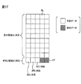
表示領域3の検出電極21とボタン領域4の検出電極31で個別化された検出回路71,72で得られる検出信号をADC80で変換した検出データは並列された検出回路71、72の並列数毎にRAM81に格納される。図11にはタッチパネル表示部(表示領域)3及びタッチキー入力部(ボタン領域)4の一面の走査から得られる検出データのRAM81上の配置を検出回路71、72の並列数毎に対応させて模式的に示している。ハッチングされた個々の矩形部分HTは個々に不要データ(無効データ)を意味し、個々の非ハッチングの矩形部分BLは個々に有効データを意味する。図11から明らかなように、ここでは駆動電極20,30の順次駆動に同期して全ての検出回路71,72の検出動作を行うものとした場合について示したものである。よって、駆動電極20、30の順次駆動に同期して検出回路71,72で得られるデータに対して、表示領域3のスキャンでは検出回路52の検出データが無効にされ、ボタン領域4のスキャンでは検出回路50の検出データが無効にされる。特に制限されないが、図11に示されるデータ格納方法では無効データHTが多くなりRAM81の使用効率が悪いと考えられる。これを改善するには、例えば図17に例示されるように、ボタン領域4からの検出データに対しては書き込み時にアドレス変換を行って有効データの格納メモリアドレスの延長上にボタン領域4からの検出データを格納すればよい。これにより無効データの領域を削減でき、図11で必要とされた8×10のサイズの記憶領域を5×10のサイズに縮小することが可能になる。
The detection data obtained by converting the detection signals obtained by the
制御回路91はタッチパネルコントローラ6B内部の制御タイミング、即ち、駆動回路40,41による駆動電極20,30の駆動に同期する検出回路71、72の検出動作と共に、ADC80の変換動作及びRAM81のアクセス動作のための制御信号を生成する。
The
制御回路91はモードレジスタ210を有する。モードレジスタ210は、タッチパネル表示部3と前記タッチキー入力部4の双方に対応する駆動端子40,41を駆動してタッチ検出動作を行うフルスキャンモード、前記タッチパネル表示部3に対応する駆動端子40だけを駆動してタッチ検出動作を行う第1パーシャルスキャンモード、又は前記タッチキー入力部4に対応する駆動端子41だけを駆動してタッチ検出動作を行う第2パーシャルスキャンモードを選択するモードデータが書き換え可能に設定されるレジスタである。制御回路91はモードレジスタ210に書き込まれたモードデータで指定されたフルスキャンモード、第1パーシャルモード、又は第2パーシャルモードによって検出フレームに対する駆動電極の駆動と検出電極からの検出動作を制御する。何れの動作モードを選択するかは、モードレジスタ210にインタフェース回路82を介してサブプロセッサ7が書き換え可能に設定したモードデータにより決定される。
The
図12にはフルスキャンモードによる動作が例示される。図13には第1パーシャルスキャンモードによる動作が例示される。図14には第2パーシャルスキャンモードによる動作が例示される。各図に示されるように、動作モードに応じて表示領域3のスキャンとボタン領域4のスキャンを取捨選択することによって低消費電力に寄与する。更に、各図の動作モードにおいて、表示領域3のスキャンでは駆動端子40、41の内で駆動端子40だけを駆動し、且つ検出回路71,72の内で検出回路71だけを動作させ、ボタン領域4のスキャンでは駆動端子40、41の内で駆動端子41だけを駆動し、且つ検出回路71,72の内で検出回路72だけを動作させるようにすることにより、各動作モードにおいて更なる低消費電力を実現することができる。
FIG. 12 illustrates an operation in the full scan mode. FIG. 13 illustrates an operation in the first partial scan mode. FIG. 14 illustrates an operation in the second partial scan mode. As shown in each figure, by selecting the scan of the
上記タッチパネル表示装置1Bによれば以下の作用効果を得ることができる。
According to the touch
(1)表示用とボタン用に共通のタッチパネルコントローラ6Bを用いてタッチパネル表示装置1Bのコストを低減することができると共に、タッチパネル11とタッチセンサ13とのそれぞれに個別の検出回路71,72を採用して個別に検出パラメータを設定することができるので、タッチパネル11とスイッチとしてのタッチセンサ13とに対する検出特性の相違がタッチ検出に悪影響を与えないようにすることができる。
(1) The cost of the touch
(2)タッチパネル11用の検出回路70と、タッチスイッチ13用の検出回路71とが個別化されているので検出回路に好適な検出特性を予め設定しておくことが容易である。
(2) Since the
(3)フルスキャンモードにより表示領域(タッチパネル表示部)3とボタン領域(タッチキー入力部)4とを併せてタッチ検出を行うことができる。第1パーシャルスキャンモードによりボタン領域を不使用にする選択が可能になる。第2パーシャルスキャンモードにより、単なる動画表示のようなときに、表示領域からの入力を不可能とする選択を行って低消費電力化を図ることができる。モードレジスタ210のモードデータによってスキャンモードを選択するから、フルスキャンモード、第1パーシャルモード、又は第2パーシャルモードの選択を容易に行うことができる。
(3) Touch detection can be performed in combination with the display area (touch panel display section) 3 and the button area (touch key input section) 4 in the full scan mode. The first partial scan mode makes it possible to select not to use the button area. With the second partial scan mode, it is possible to reduce power consumption by performing selection that disables input from the display area in the case of simple moving image display. Since the scan mode is selected based on the mode data in the
図15にはタッチパネル表示装置の詳細な第3の例が示される。同図に示されるタッチパネル表示装置1Cには、タッチキー入力部(ボタン領域)4のタッチセンサ13とタッチパネル表示部(表示領域)3のタッチパネル11との双方に対して検出回路を個別化し駆動回路を共通化したタッチパネルコントローラ6Cを採用する。図10と同様に、検出端子50には表示領域3の検出電極21が個別に結合され、検出端子52にはボタン領域4の検出電極31が個別に結合される。一方、タッチキー入力部(ボタン領域)4とタッチパネル表示部(表示領域)3とにおいて隣り合うタッチセンサ13の第2駆動電極30とタッチパネル11の第1駆動電極20が共通接続され、これが一つの駆動端子42に共通接続される。残りの駆動電極20は駆動端子40に個別に接続される。したがって、第1駆動電極20に接続された第2駆動電極30は駆動端子42によって一緒に駆動される。
FIG. 15 shows a detailed third example of the touch panel display device. In the touch
タッチパネルコントローラ6Cは検出電極50に接続される検出回路(DTC)71と検出電極52に接続される検出回路(DTC)72を有する。検出回路71,72は図5で説明した積分回路100とキャリブレーション回路101によって構成されるが、積分容量102は可変容量素子であることを要さず、また、キャリブレーション回路101は表示領域3のスキャンとボタン領域4のスキャンでカリブレーションデータの切り替えを必要としない。要するに、検出回路71の検出特性は表示領域3のタッチパネル11の回路特性に対して最適化され、検出回路72の検出特性はボタン領域4のタッチセンサ13の回路特性に対して最適化されていて、表示領域3のスキャンとボタン領域4のスキャンで検出特性の切り替えを行なうことを必要としない。したがって制御回路92は図5の制御回路90に対して検出特性を切り替えるための構成を備えていない。
The
表示領域3の検出電極21とボタン領域4の検出電極31で個別化された検出回路71,72で得られる検出信号をADC80で変換した検出データは並列された検出回路71、72の並列数毎にRAM81に格納される。図16にはタッチパネル表示部(表示領域)3及びタッチキー入力部(ボタン領域)4の一面の走査から得られる検出データのRAM81上の配置を検出回路71、72の並列数毎に対応させて模式的に示している。ハッチングされた個々の矩形部分HTは個々に不要データ(無効データ)を意味し、個々の非ハッチングの矩形部分BLは個々に有効データを意味する。図16から明らかなようにここでは駆動電極20,30の順次駆動に同期して全ての検出回路71、72の検出動作を行うものとした場合について示したものである。よって、駆動電極20、30の順次駆動に同期して検出回路71,72で得られるデータに対して、表示領域3のスキャンでは検出回路52の検出データが無効にされるが、ボタン領域4のスキャンでは双方の検出回路50、52の検出データが共に有効にされる。
The detection data obtained by converting the detection signals obtained by the
制御回路91はタッチパネルコントローラ6C内部の制御タイミング、即ち、駆動回路40,42による駆動電極20,30の駆動に同期する検出回路71、72の検出動作と共に、ADC80の変換動作及びRAM81のアクセス動作のための制御信号を生成する。
The
制御回路92はモードレジスタ210を有する。モードレジスタ210は、タッチパネル表示部3と前記タッチキー入力部4の双方に対応する駆動端子40,42を駆動してタッチ検出動作を行うフルスキャンモード、前記タッチパネル表示部3に対応する駆動端子40だけを駆動してタッチ検出動作を行う第1パーシャルスキャンモード、又は前記タッチキー入力部4に対応する駆動端子42だけを駆動してタッチ検出動作を行う第2パーシャルスキャンモードを選択するモードデータが書き換え可能に設定されるレジスタである。制御回路92はモードレジスタ210に書き込まれたモードデータで指定されたフルスキャンモード、第1パーシャルモード、又は第2パーシャルモードによって検出フレームに対する駆動電極の駆動と検出電極からの検出動作を制御する。何れの動作モードを選択するかは、モードレジスタ210にインタフェース回路82を介してサブプロセッサ7が書き換え可能に設定したモードデータにより決定される。
The
各スキャンモードの動作は図12乃至図14に示される通りである。各図に示されるように、動作モードに応じて表示領域3のスキャンとボタン領域4のスキャンを取捨選択することによって低消費電力に寄与する。更に、各図の動作モードにおいて、表示領域3のスキャンでは双方駆動端子40、42を駆動し、且つ検出回路71,72の内で検出回路71だけを動作させ、ボタン領域4のスキャンでは駆動端子40、42の内で駆動端子42だけを駆動し、且つ検出回路71,72の内で検出回路72だけを動作させるようにすることにより、各動作モードにおいて更なる低消費電力を実現することができる。
The operation in each scan mode is as shown in FIGS. As shown in each figure, by selecting the scan of the
上記タッチパネル表示装置1Cによれば上記タッチパネル表示装置1Bと同様の作用効果を得ることができる。特に、タッチパネル表示装置1Bに比べて無効な検出データ量を少なくすることができる。
According to the touch
本発明は上記実施の形態に限定されるものではなく、その要旨を逸脱しない範囲において種々変更可能であることは言うまでもない。 It goes without saying that the present invention is not limited to the above-described embodiment, and various modifications can be made without departing from the scope of the invention.
例えば、ドットマトリクス型のディスプレイパネルは液晶パネルに限定される、エレクトロルミネッセンスパネルなどであってもよい。タッチキー入力部のボタンの数は3個に限定されず適宜個数であってよい。検出回路の検出特性はキャリブレーションデータと積分容量値との双方で可変することに限定されず、いずれか一方だけを採用し、又はその他の手段を採用することも可能である。本発明はタブレットやスマートフォンなどの携帯情報端末だけでなくその他の情報端末装置などに広く適用することができる。液晶ドライバ、タッチパネルコントローラ、及びサブプロセッサはシングルチップで構成されることに限定されず、マルチチップ又はそれぞれ個別に半導体集積回路化してもよい。 For example, the dot matrix type display panel may be an electroluminescence panel, which is limited to a liquid crystal panel. The number of buttons on the touch key input unit is not limited to three and may be an appropriate number. The detection characteristic of the detection circuit is not limited to being variable by both the calibration data and the integral capacitance value, and only one of them or other means can be adopted. The present invention can be widely applied to such other information terminal device as well as a portable information terminal end, such as tablets and smartphones. The liquid crystal driver, the touch panel controller, and the sub processor are not limited to being configured by a single chip, and may be formed as a multichip or a semiconductor integrated circuit individually.
1 携帯情報端末
1A タッチパネル表示装置
1B タッチパネル表示装置
1C タッチパネル表示装置
2 筐体
3 タッチパネル表示部(表示領域)
4 タッチキー入力部(ボタン領域)
4A,4B,4C ボタン
5 コントローラデバイス
6 タッチパネルコントローラ(TPC)
6B タッチパネルコントローラ
6C タッチパネルコントローラ
7 サブプロセッサ(MPU)
8 液晶ドライバ(LCDD)
9 ホストプロセッサ(HST)
10 液晶パネル(ドットマトリクス型のディスプレイパネル)
11 タッチパネル
12 タッチキーのパターン
13 タッチセンサ
20、21 第1駆動電極
30、31 第2駆動電極
40、41 駆動端子
50,51 検出端子
52 検出端子
60 駆動回路
70 検出回路(DTC)
71 検出回路(DTC)
72 検出回路(DTC)
80 アナログディジタル変換回路(ADC)
81 RAM
82 外部インタフェース回路(IF)
90 制御回路(CNT)
91 制御回路
92 制御回路
100 積分回路
101 キャリブレーション回路
Vref プリチャージ電圧
102 積分容量(可変容量素子)
103 オペアンプ
104 チャージスイッチ
105 リセットスイッチ
106 キャリブレーションRAM
200 シーケンサ
201〜204 レジスタ
205,206 セレクタ
201 モードレジスタ
DESCRIPTION OF SYMBOLS 1
4 Touch key input section (button area)
4A, 4B,
6B
8 Liquid crystal driver (LCDD)
9 Host processor (HST)
10 Liquid crystal panel (dot matrix type display panel)
DESCRIPTION OF
71 Detection circuit (DTC)
72 Detection circuit (DTC)
80 Analog-digital conversion circuit (ADC)
81 RAM
82 External interface circuit (IF)
90 Control circuit (CNT)
91
103
200 Sequencer 201-204
Claims (18)
前記タッチパネル表示部は、相互に重ねて配置された、ドットマトリクス型のディスプレイパネルと、複数の第1駆動電極と複数の第1検出電極との交差部に交差容量がマトリクス状に形成されたタッチパネルとを有し、
前記タッチキー入力部は、相互に重ねて配置された、タッチキーのパターンと、第2駆動電極と第2検出電極との交差部に交差容量を持つタッチセンサとを有し、
前記タッチパネルコントローラは、前記第1駆動電極及び第2駆動電極に個別に接続される駆動端子と、
前記第1検出電極に個別に接続されると共に一部が前記第2検出電極に共通接続される検出端子と、
所定の順番で前記駆動端子に駆動電圧を与える駆動回路と、
前記駆動端子の駆動に同期して前記複数の検出端子に現れる電位変化によって検出信号を形成する検出回路と、
前記検出回路の検出特性を前記タッチパネル表示部からの検出時と前記タッチキー入力部からの検出時とに応じて切り替え可能な制御回路とを有する、タッチパネル表示装置。 A touch panel display device comprising: a touch panel display unit; a touch key input unit; and a touch panel controller that detects the touch by driving the touch panel display unit and the touch key input unit,
The touch panel display unit is a touch panel in which cross capacitances are formed in a matrix at intersections of a dot matrix type display panel and a plurality of first drive electrodes and a plurality of first detection electrodes, which are arranged to overlap each other. And
The touch key input unit includes a touch key pattern and a touch sensor having a cross capacitance at a crossing portion of the second drive electrode and the second detection electrode, which are arranged to overlap each other.
The touch panel controller includes drive terminals individually connected to the first drive electrode and the second drive electrode;
A detection terminal individually connected to the first detection electrode and partially connected to the second detection electrode;
A drive circuit for applying a drive voltage to the drive terminals in a predetermined order;
A detection circuit that forms a detection signal by a potential change appearing at the plurality of detection terminals in synchronization with driving of the drive terminal;
A touch panel display device comprising: a control circuit capable of switching a detection characteristic of the detection circuit according to detection from the touch panel display unit and detection from the touch key input unit.
前記制御回路は、前記タッチパネル表示部からの検出時と前記タッチキー入力部からの検出時とに応じて前記キャリブレーションデータを切り替える、タッチパネル表示装置。 2. The calibration circuit according to claim 1, wherein the detection circuit includes a calibration circuit that cancels an offset component superimposed on a potential change appearing at the detection terminal based on calibration data,
The control circuit is a touch panel display device that switches the calibration data according to detection from the touch panel display unit and detection from the touch key input unit.
前記制御回路は、前記タッチパネル表示部からの検出時と前記タッチキー入力部からの検出時とに応じて前記積分回路の積分容量値を切り替える、タッチパネル表示装置。 3. The detection circuit according to claim 1, wherein the detection circuit includes an integration circuit that integrates a potential change appearing at the detection terminal,
The control circuit is a touch panel display device that switches an integration capacitance value of the integration circuit in accordance with detection from the touch panel display unit and detection from the touch key input unit.
前記制御回路は、書き換え可能に前記可変容量素子の容量値指示データを保持するレジスタ回路と、前記タッチパネル表示部からの検出時と前記タッチキー入力部からの検出時とに応じて前記レジスタ回路から前記可変容量素子に供給する容量値指示データを選択する選択回路とを有する、タッチパネル表示装置。 In Claim 4, the said integration circuit has a variable capacity element which integrates the said potential change,
The control circuit includes a register circuit that holds the capacitance value instruction data of the variable capacitance element in a rewritable manner, and the register circuit in response to detection from the touch panel display unit and detection from the touch key input unit. and a selection circuit for selecting a capacitance value instruction data you supplied to the variable capacitance element, a touch panel display device.
前記タッチパネル表示部は、相互に重ねて配置された、ドットマトリクス型のディスプレイパネルと、複数の第1駆動電極と複数の第1検出電極との交差部に交差容量がマトリクス状に形成されたタッチパネルとを有し、
前記タッチキー入力部は、相互に重ねて配置された、タッチキーのパターンと、第2駆動電極と第2検出電極との交差部に交差容量を持つタッチセンサとを有し、
前記タッチパネルコントローラは、前記第1駆動電極及び第2駆動電極に個別に接続される駆動端子と、
前記第1検出電極に個別に接続されると共に一部が前記第2検出電極に共通接続される検出端子と、
所定の順番で前記駆動端子に駆動電圧を与える駆動回路と、
前記駆動端子の駆動に同期して前記複数の検出端子に現れる電位変化によって検出信号を形成する検出回路と、
前記検出回路の検出特性を前記タッチパネル表示部からの検出時と前記タッチキー入力部からの検出時とに応じて切り替え可能な制御回路とを有する、タッチパネルコントローラ。 A touch panel controller that detects a touch by driving a touch panel display unit and a touch key input unit,
The touch panel display unit is a touch panel in which cross capacitances are formed in a matrix at intersections of a dot matrix type display panel and a plurality of first drive electrodes and a plurality of first detection electrodes, which are arranged to overlap each other. And
The touch key input unit includes a touch key pattern and a touch sensor having a cross capacitance at a crossing portion of the second drive electrode and the second detection electrode, which are arranged to overlap each other.
The touch panel controller includes drive terminals individually connected to the first drive electrode and the second drive electrode;
A detection terminal individually connected to the first detection electrode and partially connected to the second detection electrode;
A drive circuit for applying a drive voltage to the drive terminals in a predetermined order;
A detection circuit that forms a detection signal by a potential change appearing at the plurality of detection terminals in synchronization with driving of the drive terminal;
A touch panel controller comprising: a control circuit capable of switching a detection characteristic of the detection circuit according to a detection time from the touch panel display unit and a detection time from the touch key input unit.
前記タッチパネル表示部は、相互に重ねて配置された、ドットマトリクス型のディスプレイパネルと、複数の第1駆動電極と複数の第1検出電極との交差部に交差容量がマトリクス状に形成されたタッチパネルとを有し、
前記タッチキー入力部は、相互に重ねて配置された、タッチキーのパターンと、第2駆動電極と第2検出電極との交差部に交差容量を持つタッチセンサとを有し、
前記タッチパネルコントローラは、前記第1駆動電極及び第2駆動電極に個別に接続される駆動端子と、
前記第1検出電極及び第2検出電極に個別に接続される検出端子と、
所定の順番で前記駆動端子に駆動電圧を与える駆動回路と、
前記駆動端子の駆動に同期して前記複数の検出端子に現れる電位変化によって検出信号を形成する検出回路と、
前記駆動回路及び前記検出回路の動作を制御する制御回路とを有する、タッチパネル表示装置。 A touch panel display device comprising: a touch panel display unit; a touch key input unit; and a touch panel controller that detects the touch by driving the touch panel display unit and the touch key input unit,
The touch panel display unit is a touch panel in which cross capacitances are formed in a matrix at intersections of a dot matrix type display panel and a plurality of first drive electrodes and a plurality of first detection electrodes, which are arranged to overlap each other. And
The touch key input unit includes a touch key pattern and a touch sensor having a cross capacitance at a crossing portion of the second drive electrode and the second detection electrode, which are arranged to overlap each other.
The touch panel controller includes drive terminals individually connected to the first drive electrode and the second drive electrode;
A detection terminal individually connected to the first detection electrode and the second detection electrode;
A drive circuit for applying a drive voltage to the drive terminals in a predetermined order;
A detection circuit that forms a detection signal by a potential change appearing at the plurality of detection terminals in synchronization with driving of the drive terminal;
A touch panel display device comprising: a control circuit that controls operations of the drive circuit and the detection circuit.
前記タッチパネル表示部は、相互に重ねて配置された、ドットマトリクス型のディスプレイパネルと、複数の第1駆動電極と複数の第1検出電極との交差部に交差容量がマトリクス状に形成されたタッチパネルとを有し、
前記タッチキー入力部は、相互に重ねて配置された、タッチキーのパターンと、第2駆動電極と第2検出電極との交差部に交差容量を持つタッチセンサとを有し、
前記タッチパネルコントローラは、前記第1駆動電極及び第2駆動電極に個別に接続される駆動端子と、
前記第1検出電極及び第2検出電極に個別に接続される検出端子と、
所定の順番で前記駆動端子に駆動電圧を与える駆動回路と、
前記駆動端子の駆動に同期して前記複数の検出端子に現れる電位変化によって検出信号を形成する検出回路とを有する、タッチパネルコントローラ。 A touch panel controller for performing touch detection by driving the touch panel display unit及beauty data Tchiki input unit,
The touch panel display unit is a touch panel in which cross capacitances are formed in a matrix at intersections of a dot matrix type display panel and a plurality of first drive electrodes and a plurality of first detection electrodes, which are arranged to overlap each other. And
The touch key input unit includes a touch key pattern and a touch sensor having a cross capacitance at a crossing portion of the second drive electrode and the second detection electrode, which are arranged to overlap each other.
The touch panel controller includes drive terminals individually connected to the first drive electrode and the second drive electrode;
A detection terminal individually connected to the first detection electrode and the second detection electrode;
A drive circuit for applying a drive voltage to the drive terminals in a predetermined order;
A touch panel controller, comprising: a detection circuit that forms a detection signal by a potential change appearing at the plurality of detection terminals in synchronization with driving of the drive terminal.
前記タッチパネル表示部は、相互に重ねて配置された、ドットマトリクス型のディスプレイパネルと、複数の第1駆動電極と複数の第1検出電極との交差部に交差容量がマトリクス状に形成されたタッチパネルとを有し、
前記タッチキー入力部は、相互に重ねて配置された、タッチキーのパターンと、第2駆動電極と第2検出電極との交差部に交差容量を持つタッチセンサとを有し、
前記タッチパネルコントローラは、前記第1検出電極及び第2検出電極に個別に接続される検出端子と、
前記第1駆動電極に個別に接続されると共に一部が前記第2駆動電極に共通接続される駆動端子と、
所定の順番で前記駆動端子に駆動電圧を与える駆動回路と、
前記駆動端子の駆動に同期して前記複数の検出端子に現れる電位変化によって検出信号を形成する検出回路と、
前記駆動回路及び前記検出回路の動作を制御する制御回路とを有する、タッチパネル表示装置。 A touch panel display device comprising: a touch panel display unit; a touch key input unit; and a touch panel controller that detects the touch by driving the touch panel display unit and the touch key input unit,
The touch panel display unit is a touch panel in which cross capacitances are formed in a matrix at intersections of a dot matrix type display panel and a plurality of first drive electrodes and a plurality of first detection electrodes, which are arranged to overlap each other. And
The touch key input unit includes a touch key pattern and a touch sensor having a cross capacitance at a crossing portion of the second drive electrode and the second detection electrode, which are arranged to overlap each other.
The touch panel controller includes detection terminals individually connected to the first detection electrode and the second detection electrode;
Drive terminals individually connected to the first drive electrodes and partially connected to the second drive electrodes;
A drive circuit for applying a drive voltage to the drive terminals in a predetermined order;
A detection circuit that forms a detection signal by a potential change appearing at the plurality of detection terminals in synchronization with driving of the drive terminal;
A touch panel display device comprising: a control circuit that controls operations of the drive circuit and the detection circuit.
前記タッチパネル表示部は、相互に重ねて配置された、ドットマトリクス型のディスプレイパネルと、複数の第1駆動電極と複数の第1検出電極との交差部に交差容量がマトリクス状に形成されたタッチパネルとを有し、
前記タッチキー入力部は、相互に重ねて配置された、タッチキーのパターンと、第2駆動電極と第2検出電極との交差部に交差容量を持つタッチセンサとを有し、
前記タッチパネルコントローラは、前記第1検出電極及び第2検出電極に個別に接続される検出端子と、
前記第1駆動電極に個別に接続されると共に一部が前記第2駆動電極に共通接続される駆動端子と、
所定の順番で前記駆動端子に駆動電圧を与える駆動回路と、
前記駆動端子の駆動に同期して前記複数の検出端子に現れる電位変化によって検出信号を形成する検出回路とを有する、タッチパネルコントローラ。 A touch panel controller that detects a touch by driving a touch panel display unit and a touch key input unit,
The touch panel display unit is a touch panel in which cross capacitances are formed in a matrix at intersections of a dot matrix type display panel and a plurality of first drive electrodes and a plurality of first detection electrodes, which are arranged to overlap each other. And
The touch key input unit includes a touch key pattern and a touch sensor having a cross capacitance at a crossing portion of the second drive electrode and the second detection electrode, which are arranged to overlap each other.
The touch panel controller includes detection terminals individually connected to the first detection electrode and the second detection electrode;
Drive terminals individually connected to the first drive electrodes and partially connected to the second drive electrodes;
A drive circuit for applying a drive voltage to the drive terminals in a predetermined order;
A touch panel controller, comprising: a detection circuit that forms a detection signal by a potential change appearing at the plurality of detection terminals in synchronization with driving of the drive terminal.
Priority Applications (3)
| Application Number | Priority Date | Filing Date | Title |
|---|---|---|---|
| JP2013012921A JP6045924B2 (en) | 2013-01-28 | 2013-01-28 | Touch panel display device and touch panel controller |
| US14/147,513 US9442612B2 (en) | 2013-01-28 | 2014-01-04 | Touch panel display device and touch panel controller |
| CN201410040462.6A CN103970347B (en) | 2013-01-28 | 2014-01-27 | Contact panel display device and touching control panel controller |
Applications Claiming Priority (1)
| Application Number | Priority Date | Filing Date | Title |
|---|---|---|---|
| JP2013012921A JP6045924B2 (en) | 2013-01-28 | 2013-01-28 | Touch panel display device and touch panel controller |
Publications (2)
| Publication Number | Publication Date |
|---|---|
| JP2014146092A JP2014146092A (en) | 2014-08-14 |
| JP6045924B2 true JP6045924B2 (en) | 2016-12-14 |
Family
ID=51222396
Family Applications (1)
| Application Number | Title | Priority Date | Filing Date |
|---|---|---|---|
| JP2013012921A Active JP6045924B2 (en) | 2013-01-28 | 2013-01-28 | Touch panel display device and touch panel controller |
Country Status (3)
| Country | Link |
|---|---|
| US (1) | US9442612B2 (en) |
| JP (1) | JP6045924B2 (en) |
| CN (1) | CN103970347B (en) |
Families Citing this family (16)
| Publication number | Priority date | Publication date | Assignee | Title |
|---|---|---|---|---|
| CN104679310A (en) * | 2013-11-28 | 2015-06-03 | 天津富纳源创科技有限公司 | Control method of touch screen |
| WO2016033750A1 (en) * | 2014-09-03 | 2016-03-10 | 华为技术有限公司 | Terminal, terminal control device and method |
| FR3025623B1 (en) * | 2014-09-05 | 2017-12-15 | Fogale Nanotech | CONTROL INTERFACE DEVICE AND FINGERPRINT SENSOR |
| CN104199577B (en) * | 2014-09-25 | 2017-02-15 | 深圳市华星光电技术有限公司 | Method and circuit of providing synchronous signals for touch panel by display panel |
| CN104461198B (en) * | 2014-12-03 | 2017-07-07 | 深圳市华星光电技术有限公司 | A kind of touch base plate and terminal |
| TWI569177B (en) * | 2014-12-15 | 2017-02-01 | The touch control system is planned by the arithmetic processing unit | |
| JP6495748B2 (en) * | 2015-06-05 | 2019-04-03 | 株式会社ジャパンディスプレイ | Touch detection device, display device with touch detection function, and cover member |
| CN105278753B (en) * | 2015-11-17 | 2018-05-08 | 小米科技有限责任公司 | Touch-control response method and device |
| CN106855759A (en) * | 2015-12-16 | 2017-06-16 | 小米科技有限责任公司 | Touch controlled key, contact panel and touch control terminal |
| JP6706508B2 (en) * | 2016-02-15 | 2020-06-10 | シナプティクス・ジャパン合同会社 | Touch panel device, touch controller, and touch detection method |
| JP6625212B2 (en) * | 2016-06-09 | 2019-12-25 | シャープ株式会社 | Display device and manufacturing method thereof |
| JP6802009B2 (en) | 2016-08-29 | 2020-12-16 | エルジー ディスプレイ カンパニー リミテッド | Pressure detector and its driving method |
| US20180095563A1 (en) * | 2016-10-05 | 2018-04-05 | Visteon Global Technologies, Inc. | Non-rectilinear touch surface |
| CN107450775B (en) | 2017-07-31 | 2021-08-31 | 京东方科技集团股份有限公司 | Touch substrate, preparation method thereof and touch display device |
| US11016617B2 (en) * | 2019-04-12 | 2021-05-25 | Egalax_Empia Technology Inc. | Touch sensitive processing method and apparatus and touch sensitive system |
| KR20220018116A (en) * | 2020-08-05 | 2022-02-15 | 삼성디스플레이 주식회사 | Touch detection device, display device including the same, and method for driving the same |
Family Cites Families (11)
| Publication number | Priority date | Publication date | Assignee | Title |
|---|---|---|---|---|
| JP4158935B2 (en) * | 2005-09-12 | 2008-10-01 | シャープ株式会社 | Memory card input / output device and control method thereof |
| TWI528250B (en) * | 2009-06-25 | 2016-04-01 | Elan Microelectronics Corp | Object Detector and Method for Capacitive Touchpad |
| JP2011170617A (en) * | 2010-02-18 | 2011-09-01 | On Semiconductor Trading Ltd | Electrostatic capacity type touch sensor |
| TWI420826B (en) * | 2010-04-09 | 2013-12-21 | Memsor Corp | Capacitive sensor having calibration mechanism and capacitive sensing method |
| JP2012103797A (en) * | 2010-11-08 | 2012-05-31 | Sony Corp | Input device, coordinate detection method and program |
| JP5432193B2 (en) * | 2011-01-18 | 2014-03-05 | 株式会社ジャパンディスプレイ | Display device |
| JP5726606B2 (en) * | 2011-04-13 | 2015-06-03 | 株式会社ジャパンディスプレイ | Display panel with touch detection function, driving method thereof, driving circuit, and electronic device |
| JP5811603B2 (en) | 2011-06-07 | 2015-11-11 | ソニー株式会社 | Information processing terminal and method, program, and recording medium |
| JP5231605B2 (en) * | 2011-06-10 | 2013-07-10 | シャープ株式会社 | Touch panel controller and electronic device using the same |
| CN102799330B (en) * | 2012-07-26 | 2016-04-13 | 惠州Tcl移动通信有限公司 | Based on the sensor connecting circuit of electronic equipment and control method thereof and electronic equipment |
| CN102841716B (en) * | 2012-08-21 | 2015-08-05 | 北京京东方光电科技有限公司 | A kind of capacitance type in-cell touch panel and display device |
-
2013
- 2013-01-28 JP JP2013012921A patent/JP6045924B2/en active Active
-
2014
- 2014-01-04 US US14/147,513 patent/US9442612B2/en active Active
- 2014-01-27 CN CN201410040462.6A patent/CN103970347B/en active Active
Also Published As
| Publication number | Publication date |
|---|---|
| CN103970347A (en) | 2014-08-06 |
| JP2014146092A (en) | 2014-08-14 |
| US9442612B2 (en) | 2016-09-13 |
| US20140210776A1 (en) | 2014-07-31 |
| CN103970347B (en) | 2018-03-30 |
Similar Documents
| Publication | Publication Date | Title |
|---|---|---|
| JP6045924B2 (en) | Touch panel display device and touch panel controller | |
| US8970527B2 (en) | Capacitive touch panel having mutual capacitance and self capacitance sensing modes and sensing method thereof | |
| JP6012437B2 (en) | Semiconductor device and electronic equipment | |
| JP4945345B2 (en) | Display device with touch panel | |
| KR101480315B1 (en) | Display device with integrated touch screen and method for driving the same | |
| KR101480314B1 (en) | Display device with integrated touch screen and method for driving the same | |
| US9904407B2 (en) | Touch sensor, display apparatus including the same, and method of sensing touch panel | |
| US8878802B2 (en) | Display unit, display method, and electronic system | |
| CN107422929B (en) | Touch panel controller and semiconductor device | |
| JP6211409B2 (en) | Display device | |
| KR101746022B1 (en) | Touch sensor and display apparatus including the same | |
| US20150062062A1 (en) | Touch Integrated Circuit And Display Device Integrated With Touch Screen Using The Same | |
| US10001877B2 (en) | Semiconductor device | |
| JP2011002926A (en) | Display device with tactile exhibition function | |
| US10222916B2 (en) | Device and method for self-capacitance touch sensing | |
| KR20150079241A (en) | Display device with integrated touch screen and method for driving thereof | |
| JP6242717B2 (en) | Semiconductor device and electronic equipment | |
| CN103853402A (en) | Semiconductor device and electronic device | |
| JP2022528806A (en) | Electronic device with fingerprint detection function | |
| JP6022320B2 (en) | Liquid crystal display | |
| KR20160115644A (en) | Driver integrated circuit, driving method, and touch display system | |
| JP6034442B2 (en) | Semiconductor device | |
| US20230367425A1 (en) | Touch Display Device and Weighted Touch Sensing Method of Touch Controller | |
| US11822753B2 (en) | Touch sensor and touch sensing method | |
| JP5988283B2 (en) | Touch sensor panel controller and semiconductor device |
Legal Events
| Date | Code | Title | Description |
|---|---|---|---|
| A621 | Written request for application examination |
Free format text: JAPANESE INTERMEDIATE CODE: A621 Effective date: 20151211 |
|
| A131 | Notification of reasons for refusal |
Free format text: JAPANESE INTERMEDIATE CODE: A131 Effective date: 20160915 |
|
| A977 | Report on retrieval |
Free format text: JAPANESE INTERMEDIATE CODE: A971007 Effective date: 20160914 |
|
| A521 | Request for written amendment filed |
Free format text: JAPANESE INTERMEDIATE CODE: A523 Effective date: 20161025 |
|
| TRDD | Decision of grant or rejection written | ||
| A01 | Written decision to grant a patent or to grant a registration (utility model) |
Free format text: JAPANESE INTERMEDIATE CODE: A01 Effective date: 20161110 |
|
| A61 | First payment of annual fees (during grant procedure) |
Free format text: JAPANESE INTERMEDIATE CODE: A61 Effective date: 20161116 |
|
| R150 | Certificate of patent or registration of utility model |
Ref document number: 6045924 Country of ref document: JP Free format text: JAPANESE INTERMEDIATE CODE: R150 |
|
| RD02 | Notification of acceptance of power of attorney |
Free format text: JAPANESE INTERMEDIATE CODE: R3D02 |
|
| R250 | Receipt of annual fees |
Free format text: JAPANESE INTERMEDIATE CODE: R250 |
|
| S111 | Request for change of ownership or part of ownership |
Free format text: JAPANESE INTERMEDIATE CODE: R313113 |
|
| R350 | Written notification of registration of transfer |
Free format text: JAPANESE INTERMEDIATE CODE: R350 |
|
| R250 | Receipt of annual fees |
Free format text: JAPANESE INTERMEDIATE CODE: R250 |
|
| R250 | Receipt of annual fees |
Free format text: JAPANESE INTERMEDIATE CODE: R250 |
|
| S111 | Request for change of ownership or part of ownership |
Free format text: JAPANESE INTERMEDIATE CODE: R313113 |
|
| S531 | Written request for registration of change of domicile |
Free format text: JAPANESE INTERMEDIATE CODE: R313531 |
|
| R350 | Written notification of registration of transfer |
Free format text: JAPANESE INTERMEDIATE CODE: R350 |
|
| R250 | Receipt of annual fees |
Free format text: JAPANESE INTERMEDIATE CODE: R250 |
|
| R250 | Receipt of annual fees |
Free format text: JAPANESE INTERMEDIATE CODE: R250 |