JP6043772B2 - Liquid medicine supply device - Google Patents
Liquid medicine supply device Download PDFInfo
- Publication number
- JP6043772B2 JP6043772B2 JP2014210673A JP2014210673A JP6043772B2 JP 6043772 B2 JP6043772 B2 JP 6043772B2 JP 2014210673 A JP2014210673 A JP 2014210673A JP 2014210673 A JP2014210673 A JP 2014210673A JP 6043772 B2 JP6043772 B2 JP 6043772B2
- Authority
- JP
- Japan
- Prior art keywords
- liquid medicine
- supply
- bottle
- nozzle
- medicine bottle
- Prior art date
- Legal status (The legal status is an assumption and is not a legal conclusion. Google has not performed a legal analysis and makes no representation as to the accuracy of the status listed.)
- Active
Links
- 239000003814 drug Substances 0.000 title claims description 298
- 239000007788 liquid Substances 0.000 title claims description 295
- XLYOFNOQVPJJNP-UHFFFAOYSA-N water Substances O XLYOFNOQVPJJNP-UHFFFAOYSA-N 0.000 claims description 8
- 238000007599 discharging Methods 0.000 claims description 2
- 229940079593 drug Drugs 0.000 claims 1
- 238000003780 insertion Methods 0.000 description 8
- 230000037431 insertion Effects 0.000 description 8
- 230000003028 elevating effect Effects 0.000 description 7
- 230000002093 peripheral effect Effects 0.000 description 7
- 238000001514 detection method Methods 0.000 description 5
- 230000001965 increasing effect Effects 0.000 description 5
- 238000005192 partition Methods 0.000 description 5
- 238000011109 contamination Methods 0.000 description 3
- 239000000725 suspension Substances 0.000 description 3
- 238000013459 approach Methods 0.000 description 2
- 230000005587 bubbling Effects 0.000 description 2
- 210000000078 claw Anatomy 0.000 description 2
- 238000004140 cleaning Methods 0.000 description 2
- 230000003247 decreasing effect Effects 0.000 description 2
- 230000000694 effects Effects 0.000 description 2
- 238000005187 foaming Methods 0.000 description 2
- 238000000638 solvent extraction Methods 0.000 description 2
- 239000003795 chemical substances by application Substances 0.000 description 1
- 238000006073 displacement reaction Methods 0.000 description 1
- 239000006260 foam Substances 0.000 description 1
- 230000009191 jumping Effects 0.000 description 1
- 238000012423 maintenance Methods 0.000 description 1
- 238000004519 manufacturing process Methods 0.000 description 1
- 230000003287 optical effect Effects 0.000 description 1
- 238000002360 preparation method Methods 0.000 description 1
- 230000000717 retained effect Effects 0.000 description 1
- 238000004804 winding Methods 0.000 description 1
Images


Description
本発明は、供給ボトルから水薬ボトルに水薬を供給するようにする水薬供給装置に関する。 The present invention relates to a liquid medicine supply device that supplies liquid medicine from a supply bottle to a liquid medicine bottle.
従来から、病院や薬局等の医療機関では、水薬を供給ボトルから水薬ボトルに供給するようにした水薬供給装置が使用されている(例えば、下記特許文献1参照)。この水薬供給装置では、底板側に回転駆動部を設け、この回転駆動部に上方が下方に比べて大径となっているベースを設け、このベースの上端部に供給ボトルを複数載置する載置板を設け、載置板に供給ボトルを載置して、供給ボトルと水薬ボトルとを供給管で接続し、供給管を供給ポンプに接続して、供給ポンプの駆動により必要な水薬を選択された供給ボトルから、供給管の先端部を下方に向けて水薬ボトルに必要な水薬を供給するようにしている。 Conventionally, in medical institutions such as hospitals and pharmacies, a liquid medicine supply device that supplies liquid medicine from a supply bottle to a liquid medicine bottle has been used (for example, see Patent Document 1 below). In this liquid medicine supply device, a rotation drive unit is provided on the bottom plate side, a base whose upper side is larger than the lower side is provided in the rotation drive unit, and a plurality of supply bottles are placed on the upper end of the base. A mounting plate is provided, a supply bottle is mounted on the mounting plate, the supply bottle and the liquid medicine bottle are connected by a supply pipe, the supply pipe is connected to a supply pump, and the necessary water is driven by driving the supply pump. The liquid medicine required for the liquid medicine bottle is supplied from the supply bottle in which the medicine is selected with the tip of the supply pipe directed downward.
上記従来の水薬供給装置では、先端部を下方に向けた供給管から水薬ボトルに水薬を供給すると、水衝作用(水勢)によって水薬ボトル内で水薬が泡だってしまい易く、水薬が適量だけ供給ボトルから供給されたかどうか(払い出されたかどうか)が外観的に判断しにくくなってしまう。すなわち、処方箋どおりの水薬量となっているかどうかが判断しにくくなってしまうという課題がある。 In the above conventional liquid medicine supply device, when the liquid medicine is supplied to the liquid medicine bottle from the supply pipe with the tip portion directed downward, the liquid medicine is easily bubbled in the liquid medicine bottle due to the water impact action (water force). It becomes difficult to judge visually whether or not an appropriate amount of medicine has been supplied from the supply bottle (whether or not it has been dispensed). That is, there is a problem that it is difficult to determine whether or not the amount of liquid medicine is as prescribed.
そこで本発明は、上記課題に鑑み、水薬ボトル内の水薬が処方箋どおりになっているかどうかを判断し易く、さらには処方箋どおりの量の水薬を確実に水薬ボトルに供給できる水薬供給装置の提供を課題とする。 Therefore, in view of the above problems, the present invention makes it easy to determine whether or not the liquid medicine in the liquid medicine bottle is in accordance with the prescription, and furthermore, the liquid medicine that can reliably supply the liquid medicine in the amount according to the prescription to the liquid medicine bottle. It is an object to provide a supply device.
本発明の水薬供給装置は、複数の供給ボトルにそれぞれ接続される複数の供給ノズルが上下軸線周りに配置されており、処方箋に応じて各供給ボトルから各供給ノズルを介して水薬ボトルに水薬を選択的に供給する水薬供給装置であって、前記各供給ノズルを前記上下軸線周りに移動させるための回転駆動部と、前記水薬ボトルが載置され、昇降自在な載置台と、前記載置台を昇降させるための昇降装置と、を備え、前記水薬ボトルに供給すべき水薬を収容する前記供給ボトルに接続される前記供給ノズルが前記水薬ボトルに水薬を供給可能な位置にない場合には、前記回転駆動部が駆動することで、当該供給ノズルが前記水薬ボトルに水薬を供給可能な位置に移動し、前記昇降装置が駆動することで、前記水薬ボトルが供給位置に移動して前記水薬ボトルの上端口部が前記供給ノズルに接近し、この後、当該供給ノズルから前記水薬ボトルに水薬を供給することを特徴としている。 In the liquid medicine supply device of the present invention, a plurality of supply nozzles respectively connected to a plurality of supply bottles are arranged around the vertical axis, and from each supply bottle to each liquid medicine bottle via each supply nozzle according to a prescription. A liquid medicine supply device for selectively supplying liquid medicine, wherein a rotation drive unit for moving each supply nozzle around the vertical axis, a mounting table on which the liquid medicine bottle is placed and which can be moved up and down, An elevating device for raising and lowering the mounting table, and the supply nozzle connected to the supply bottle storing the liquid medicine to be supplied to the liquid medicine bottle can supply liquid medicine to the liquid medicine bottle If it is not in the correct position, the rotation drive unit is driven to move the supply nozzle to a position where the liquid medicine can be supplied to the liquid medicine bottle, and the elevating device is driven to drive the liquid medicine. to move the bottle is in the supply position Serial approaches the upper end opening portion of the liquid medicine bottle to the supply nozzle, thereafter, it is characterized by supplying liquid medicine in the liquid medicine bottle from the supply nozzle.
また、前記昇降装置の駆動が停止した状態で、前記供給ノズルから前記水薬ボトルに水薬を供給するものとできる。
また、前記各供給ノズルをそれぞれ保持する複数の保持部を備え、各保持部は、前記回転駆動部が駆動することで前記上下軸線周りに移動するものとできる。
また、前記各供給ボトルが載置される載置体を備え、前記載置体は、前記保持部とともに前記上下軸線周りに移動するものとできる。
また、前記各供給ボトルは、前記載置体に着脱自在に設けられるものとできる。
Further, the liquid medicine can be supplied from the supply nozzle to the liquid medicine bottle in a state where the driving of the lifting device is stopped.
In addition, a plurality of holding units that hold the supply nozzles may be provided, and the holding units may be moved around the vertical axis when the rotation driving unit is driven.
Moreover, the said mounting bottle is equipped with the mounting body in which each said supply bottle is mounted, and the said mounting body shall move to the said up-down axis line with the said holding part.
The supply bottles can be detachably provided on the mounting body.
また、前記各供給ボトルに収容された水薬を前記各供給ノズルからそれぞれ吐出させるための複数の供給ポンプを備えるものとできる。
また、前記載置台は、前記水薬ボトルの底部が挿入される凹部を有するものとできる。
また、前記供給ノズルから吐出される水薬の有無を検出するためのセンサを備えるものとできる。
また、前記水薬ボトルに対して水薬を供給するとき、供給の終了に近くなる時点で、前記供給ノズルから吐出される水薬の量を減少させるものとできる。
Moreover, the liquid medicine accommodated in each said supply bottle can be equipped with the several supply pump for discharging from each said supply nozzle, respectively.
Moreover, the said mounting stand can have a recessed part in which the bottom part of the said liquid medicine bottle is inserted.
Moreover, it can be equipped with the sensor for detecting the presence or absence of the liquid medicine discharged from the said supply nozzle.
In addition, when the liquid medicine is supplied to the liquid medicine bottle, the amount of liquid medicine discharged from the supply nozzle can be reduced at the time when the supply is nearly finished.
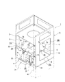
以下、本発明に係る水薬供給装置の実施形態を、図1ないし図10に基づいて説明する。図1の一部省略正面図に示すように、水薬供給装置1は、患者に対して処方される水薬2を、処方箋に応じるべく予め準備している必要な水薬2を収容した供給ボトル3から水薬2を導出して、患者に必要な水薬2を収容した水薬ボトル4とするためのもので、供給ボトル3を載置する載置体5が本体6の天板7側に吊持された構成を有し、本体6の底板8と載置体5との間に、隙間10が設けられた構成を有する。以下にその構成を詳述する。
Hereinafter, an embodiment of a liquid medicine supply device according to the present invention will be described with reference to FIGS. 1 to 10. As shown in the partially omitted front view of FIG. 1, the liquid medicine supply device 1 supplies the
水薬供給装置1の本体6は、天板7と底板8と左右の両側板11,11と背板12と前板13とを有する。前板13は使用者に対して、上下方向の支軸(図示せず)周りに開閉自在に設けられている。特に側板11,11と背板12には、その板面中央部に開口11A,12Aが形成されている。
The
水薬供給装置1は、この本体6内に配置される環状の前記載置体5と、載置体5を吊持する吊持手段15と、吊持手段15を含めて載置体5を上下方向軸線16周りに間欠的に回転駆動させるための回転駆動部17と、載置体5に周方向に所定間隔置きに配置される供給ボトル3毎に設けられる供給ポンプ18(この種の水薬供給装置に用いられるポンプである)と、選択された供給ボトル3に対応する供給ポンプ18を駆動するためのポンプ駆動部20と、各供給ポンプ18に一端側が挿入される水薬供給管21の他端側に取付けられた中継ノズル19と、一端側が中継ノズル19に取付けられた水薬管29の他端側に取付けられる供給ノズル22と、供給ノズル22を保持する保持部23と、水薬ボトル4を載置する載置台24と、この載置台24を昇降させるための昇降装置25と、供給ノズル22の水薬吐出口部26から吐出されている水薬2の有無を検出するための水薬センサ27とを備える。
The liquid medicine supply apparatus 1 includes the
図7ないし図10に示すように、水薬ボトル4の形状は、下部に同一断面に形成されているボトル胴体4aと、ボトル胴体4aの上部から、上方に向かうほど縮径された首部4bと、首部4bから上方に向けて延長された同一断面の口部4cとを有する。
As shown in FIGS. 7 to 10, the shape of the
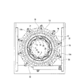
底板8は本体6の上下方向途中に配置された平板状に形成されている。天板7は中心が円形に中抜きされた平板状に形成されている。図3の断面図に示すように、回転駆動部17は天板7に設けられている。回転駆動部17は天板7の上面に載置された回転駆動モータ28と、天板7の下面に上下方向軸線16周りに回転自在に支持されて内周面の上下方向中心に水平に形成された環状の突条30を有する回転環体31と、回転環体31の下面に固着された環状薄板状の歯車板32と、前記回転駆動モータ28の駆動軸に取付けられて歯車板32の外周辺に形成された歯33に噛合する駆動歯車33aと、天板7の下面に上下方向軸線16周りにその場回転自在に取付けられて外周面に前記突条30に嵌合する凹条34を有する複数の支持ローラ35とを有する。各供給ポンプ18は、回転駆動部17(回転駆動モータ28)の間欠駆動に連動して供給ポンプ18毎に駆動するよう構成されている。
The
歯車板32の下面に、供給ポンプ18を取付けるための取付け枠体36が歯車板32の周方向に隣接するように設けられている。各取付け枠体36は、径方向外周面に供給ポンプ18の本体部37が組付けられる矩形の平板部38と、この平板部38の各辺に径方向内方に向けて突出する矩形のフレーム部40とを有する。フレーム部40の上部は前記歯車板32の下面に、例えばネジ止めされることで固定されている。平板部38はまた、その下方寄りに供給ポンプ18を駆動させる従動歯車(従動係止回転爪)41を径方向内方に突出させるための挿通孔43が形成されている。供給ポンプ18の本体部37は、平板部38の径方向外側面にネジ止め等により固定されている。供給ポンプ18の従動歯車41は、挿通孔43から平板部38の径方向内方に突出しておりその外周部は取付けプレート44によって、平板部38の径方向内方面からネジ止め等されている。この構成によって、各供給ポンプ18は、それぞれ取付け枠体36に確実に固定されるとともに、従動歯車41は、水平軸線45周りにそれぞれその場回転自在な構成となっている。
An
図5に示すように、ポンプ駆動部20は、取付け枠体36で囲まれる領域の径方向内方に配置されている。このポンプ駆動部20は、水平に保持されたサーボモータ46と、サーボモータ46の駆動軸の先端に設けられた駆動歯車47(駆動係止回転爪)と、サーボモータ46の側部に設けられてサーボモータ46を選択された供給ポンプ18の従動歯車41に向けて横方向(水平方向)に前進させるためのソレノイド48と、サーボモータ46を後退させる方向に付勢するバネ50と、サーボモータ46の位置を検出するする位置検出センサ51と、サーボモータ46の変位位置を調整可能なストッパ52とを有する。なお、図示しないが、ポンプ駆動部20は、支持板部材に載置され、且つ横方向に移動可能に支持されている。
As shown in FIG. 5, the
取付け枠体36のフレーム部40の下部に環状のノズル取付け板53がネジ止め等により固定されている。ノズル取付け板53の外周部には周方向に供給ポンプ18毎の間隔に応じて、供給ポンプ18によって送られる水薬2を下方に設けられる水薬ボトル4へ向けて中継する前記中継ノズル19を装着するための装着片55が、径方向外方に突出するよう形成されている。この装着片55の板面にノズル挿通孔55a、あるいはノズル装着用切欠がそれぞれ形成されている。中継ノズル19は適宜の手段によりノズル挿通孔55aに着脱自在に装着されている。例えば図1および図3では、ノズル取付け板53上に上下方向軸線16a周りに回動自在に取付けたフック部19aを有する保持具19Aによって、保持される構成である。
An annular
図1および図3に示すように、ノズル取付け板53の下面に、上下方向に実質的に同一高さを有する板状の仕切り体56が、供給ボトル3に応じた数だけネジ止め等により取付けられている。仕切り体56の下端部には、供給ボトル3を載置するための環状且つ板状の載置体5が、仕切り体56にネジ止め等により固定されている。すなわち、載置体5を天板7に吊持する吊持手段15として、回転環体31、歯車板32、各取付け枠体36、ノズル取付け板53、および仕切り体56の連続構造を有している。
As shown in FIGS. 1 and 3, plate-
載置体5上で仕切り体56間に、供給ボトル3を載置するための載置皿57が設けられている。載置皿57は載置体5の上面に固定されて供給ボトル3の底面が載置される受け板58と、この受け板58に磁力により着脱自在に装着される受け筒60とを有する。供給ボトル3の下部は受け筒60に挿入されて受け板上に配置される。載置体5には、供給ボトル3毎に水薬管29の途中を挿通保持するための径方向内方へ向けて切欠いた保持凹部5Aが形成されている。この保持凹部5Aは、径方向外方側が水薬管29の径にくらべてわずかに幅狭の装着切欠5aとされており、径方向内方が拡径された挿通部5bとされている。
A mounting
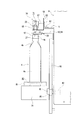
次に、載置体5の供給ポンプ18毎の間隔に応じて設けられる供給ノズル22と、これを保持するための前記保持部23について説明する。この保持部23は、供給ノズル22の向きを上下方向軸線16bに対して傾斜角度を変更可能とする変更機構によって構成されている。この変更機構の構成は、供給ノズル22の傾斜角度を水薬ボトル4の形状に合わせて、制御装置によって自動的に制御する構成であってもよいし、機構的に手動で行う構成であってもよい。この場合、手動で行う構成を採用している。何れの傾斜角度であっても、供給ノズル22の水薬吐出口部26はその角度に応じた高さ位置に保持されることになる。
Next, the
変更機構は、載置体5の外周部上面にネジ止め等によって固定される取付けフランジ61を有する。この取付けフランジ61は、載置体5の外周部上面に取付けられる止め板62とこの止め板62の径方向外方から上方に向けて折曲された案内面部63とを有する。案内面部63の板面には周方向に沿う第一長孔64が形成されている。変更機構は、さらに供給ノズル22を取付ける取付け部65を有する。取付け部65は案内面部63の径方向外方に重ねられる重ね板66と、この重ね板66の下端部から径方向外方に向けて折曲される板状の保持片67とを有する。重ね板66には、第一長孔64の径方向外方に重ねられる第二長孔73が形成されている。第二長孔73は、重ね板66の高さ方向に沿う長孔とされている。
The changing mechanism has a mounting
保持片67の一方寄りには供給ノズル22を挿通するための挿通孔が形成されている。さらに、保持片67の上面には、挿通孔に挿通した供給ノズル22の円筒部68をサイドから嵌合して固定する保持ブロック70がネジ孔71を介して保持片67の上面に取付けられている。保持ブロック70の挿通孔49側には供給ノズル22の円筒部68に嵌合する半円筒状の嵌合凹部72が形成されている。上記構成の変更機構では、第一長孔64と第二長孔73とを重ねて両長孔64,73にビス等の止め具を挿通することで、取付けフランジ61に取付け部65が固定されることになる。さらに、第一長孔64に対する第二長孔73の傾斜角度θを変更することで、取付けフランジ61に対する取付け部65の傾斜角度θ1が変更されることになる。なお、供給ノズル22は、円筒部68と先端が先細りの円錐台形状に形成された水薬吐出口部26から一体に形成されている。変更機構において、第一長孔64と第二長孔73との重なり角度や重なり高さ等を変更することで、取付け部65は取付けフランジ61に対して、第一長孔64と第二長孔73の長さ等に応じて位置変更も可能であることは勿論である。
An insertion hole for inserting the
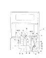
次に、図7および図8に基づいて、水薬ボトル4を載置する前記載置台24および、この載置台24を供給ノズル22に対して昇降させるための昇降装置25について説明する。載置台24は本体6の前面下部に配置されており、前面下部を上方から下方に向けて切欠いた正面視して矩形の切欠74の両側壁部75,76に案内されて昇降自在とされた案内板部材77と、この案内板部材77の前面下部に前方に突出するよう固定された固定台78と、この固定台78の上面に水薬ボトル4を直接載置して、水薬ボトル4の底部が挿入される凹部80を有する受け皿81とを一体、または別体に有する。
Next, based on FIGS. 7 and 8, the mounting table 24 on which the
昇降装置25は、昇降用モータ82と、本体6の前面下部に配置されて昇降用モータ82の駆動によって駆動するベルト機構83とを有する。昇降用モータ82は本体6の前面下部の裏面に、その駆動軸84が前方に突出するよう取付けられ、駆動軸84には、駆動プーリ85が本体6の前面下部から水平方向前方に突出するように取付けられている。ベルト機構83は、案内板部材77の側方部に固定されたベルト固定具86と、駆動プーリ85の斜め下方に配置されたテンションプーリ87と、上下方向に離間して配置された巻回プーリ90,91と、各プーリ85,87,90,91に巻回されるベルト92とを有する。なお、ベルト92をタイミングベルトとし、これら各プーリ85,87,90,91は、その周囲にタイミングベルトに噛合う凹凸部を有するものであってもよい。さらに、テンションプーリ87は、不図示の揺動軸周りに揺動して、ベルト92に適切なテンションを付与できる構成とすることが好ましい。昇降装置25の駆動については、不図示の駆動スイッチを操作することで行うよう構成している。
The elevating
次に、供給ノズル22の水薬吐出口部26から吐出されている水薬2の有無を検出するための光学センサとしての水薬センサ27について説明する。水薬センサ27は本体6の前面下部に前方に突出するよう左右に離間した取付けプレート93,94の左右対向面93a,94aの下面それぞれに発光部95と受光部96として、両者が基準面から同一高さとなるよう水薬センサ27の本体がネジ止め等により、取付けられている。
Next, the
取付けプレート93,94は、正面視して載置体5よりもわずかに下方に位置している。前記底板8は載置体5のさらに下方に、少なくとも手指や製造具が入る上下方向高さを有する隙間(空間)を介して本体6に装着されている。
The mounting
この構成により、水薬センサ27は、供給ノズル22(水薬吐出口部26)の側方近傍に配置されている。なお、左右対向面93a,94aの何れに発光部95、受光部96を取付けてもよい。水薬センサ27では、発光部95側からの発光量に対する受光部96の受光量を予め関係付けておいて、供給ノズル22から水薬2が吐出している場合はその分だけ発光量と受光量の関係が崩れることから、直接的に水薬2の吐出の有無を検出することになる。
With this configuration, the
水薬センサ27は、発光部95、受光部96間の水薬ボトル4の上端口部97の有無、すなわち水薬ボトル4に水薬2を供給可能か否かを検出する機能を兼用している。水薬センサ27が水薬ボトル4の存在を検出すると、その信号が制御装置を介して昇降用モータ82の駆動部に出力されて、水薬ボトル4の上端口部97が水薬センサ27からわずかに下方に位置するまで載置台24を下降させるよう制御装置によって制御される。このように水薬ボトル4の上端口部97を水薬センサ27からわずかに下方に位置させることで、水薬センサ27間に検出空間を確保でき、その後、水薬センサ27は水薬2の有無のみを検出することになるから、水薬2の検出を正確に行うことができる。なお、水薬センサ27は、昇降用モータ82の駆動部、回転駆動モータ28の駆動部、各供給ポンプ18の駆動部に電気的に接続されている。
The
上記構成の水薬供給装置1において、載置体5の各載置皿57に、水薬2が充填された供給ボトル3を載置し、各水薬供給管21の一端側を供給ボトル3内に挿入し、その途中を供給ポンプ18に挿通し、さらに他端側を中継ノズル19に接続し、さらに水薬管29の一端側を中継ノズル19に接続するとともに他端側を供給ノズル22に接続する。また、固定台78に、水薬ボトル4を受け皿81に載置する。
In the liquid medicine supply device 1 having the above-described configuration, the
そして駆動スイッチを操作(オン操作)することで、水薬センサ27が水薬ボトル4の上端口部97を検出していない場合は、昇降装置25すなわち昇降用モータ82が駆動し、これによりベルト92が回転し、ベルト92と案内板部材77とはベルト固定具86を介して固定されているから案内板部材77が上昇し、水薬センサ27が水薬ボトル4の上端口部97を検出した時点で昇降装置25(昇降用モータ82)が駆動を停止させ、上記したように水薬ボトル4の上端口部97が水薬センサ27からわずかに下方に位置するまで載置台24が下降する。供給ノズル22の傾斜角度θについては、第一長孔64に対する第二長孔73の周方向位置や高さ方向位置を調整することで、取付けフランジ61の案内面部63に対して重ね板66の傾斜角度を調整し、水薬ボトル4の形状にあわせて、予め水薬ボトル4(上端口部97)に対して斜め方向から吐出されるように設定しておくことが好ましい。
When the
このように予め準備をしておき、水薬2の供給を開始するものであるが、初期状態においては、供給ボトル3すなわち供給ノズル22が周方向で、水薬ボトル4に水薬2を供給可能な位置にある場合はよいが、そうでない場合も考えられる。このような場合のため、本体駆動のスイッチ(図示せず)を操作(オン操作)した時点で、回転駆動モータ28を駆動させて、水薬ボトル4に最も近い供給ボトル3すなわち供給ノズル22が周方向に水薬ボトル4に水薬2を供給可能な位置に至るまで載置体5を回転させることとする。この場合、特別に上記位置を検出するセンサを設けておいて、そのセンサからの検出信号によって、制御装置が水薬ボトル4に最も近い供給ボトル3が水薬ボトル4に水薬2を供給可能な位置に至るまで載置体5を回転させることが好ましい。このとき、回転駆動モータ28を駆動すると駆動歯車が回転駆動し、この駆動歯車33aは歯車板32の歯33に噛合しているから、歯車板32に一体に設けられている回転環体31が、その突条30が支持ローラ35の凹条34と嵌合しつつ上下方向軸線16周りに回転駆動することになる。また、歯車板32の下方に一体設けられている取付け枠体36、供給ポンプ18、ノズル取付け板53、仕切り体56、および載置体5が上下方向軸線16周りに回転することになる。
In this way, the preparation of the
ポンプ駆動部20においてソレノイド48が駆動してバネ50の弾性に抗してサーボモータ46が供給ポンプ18の従動歯車41に向けて横方向に前進し、駆動歯車47が従動歯車41に係合(噛合)したことを位置検出センサ51が検出すると、サーボモータ46が駆動して駆動歯車47とともに従動歯車41が回転し、供給ポンプ18が駆動することになる。そして、供給ポンプ18が駆動すると、供給ボトル3内の水薬2が吸い上げられ、水薬供給管21から中継ノズル19を通り、水薬管29に至り、さらに供給ノズル22の水薬吐出口部26から水薬2が吐出する。このとき、供給ノズル22は上下方向軸線16に対して傾斜しているから、水薬ボトル4の底面に直角に当ることがなく、例えば水薬ボトル4の内壁面に対して斜めに吐出して当ることになる。つまり、水薬ボトル4の内壁面に対して斜めに当る分だけ水衝現象に伴う水薬2の泡立ちが小さくなることになり、水薬2が水薬ボトル4内で泡立つのを効果的に防止でき、したがって、水薬ボトル4内の水薬2の量を容易に確認することができる。
In the
供給ノズル22の傾斜角度によっては、水薬2が水薬ボトル4の口部4cや首部4bに当ることが考えられるが、何れにしても、水薬ボトル4の内面に直角に当ることを防止すれば、従来底面に直角な方向に当っていた場合に比べて水薬2の泡立ちを抑制することができるから、水薬ボトル4内の水薬2の量を確認し易い。
Depending on the inclination angle of the
水薬2を水薬ボトル4に供給する際は、供給の開始時には水薬2の量を多くし(水薬吐出口部26の口径は同一であるから水薬2の吐出速度を速くすることなる)、供給の終了に近くなるほど少なく供給する(水薬2の吐出速度を遅くすることになる)ようにする。そうすると、水薬2の水薬ボトル4外への飛び散りが抑制できて、水薬ボトル4周りの汚れを抑制でき、したがってその分だけ水薬ボトル4内に供給される水薬2の実質量を正確にすることができる。このため、本発明の実施形態では、上記のように水薬2の供給量を変更するよう制御装置によって制御している。
When the
なお、初期状態での水衝現象による水薬2の泡立ちをいっそう確実に抑制するために、供給初期状態では水薬2の量を少なくすることも考えられる。この場合、水薬2の供給終了に近付くまでは水薬2を多く供給し、供給終了に近くなった時点では、再び水薬2の供給量が少なくなるよう制御することで、水薬2の供給時間を短縮することが可能になるとともに、水薬2の水薬ボトル4外への飛び散りを抑制することができる。
In addition, in order to suppress more reliably the foaming of the
ところで、従来では、供給ポンプ18が駆動しているにも拘わらず、例えば供給ボトル3内の水薬2が不足したり、中継ノズル19部分から水薬2が漏れたりしていて、供給ノズル22から水薬2が吐出されていない場合であっても、制御装置が供給ポンプ18の駆動を検出することで水薬2が供給ノズル22から吐出しているものとして判断していたが、この実施形態では、実際に供給ノズル22から水薬2が吐出されているかどうか、すなわち水薬センサ27からの受光量信号によって水薬2の有無を検出することになるから、上記のような不都合が解消でき、水薬2が供給ノズル22から吐出されているかどうかを確実に知ることができる。さらに水薬センサ27は、水薬ボトル4の位置が水薬2を供給可能であるかどうかを検出するセンサを兼用しているから、特別に水薬ボトル4の位置を検出するセンサを設ける必要がなくなり、構造が簡単になるとともに、コストの低減が可能になる。
By the way, conventionally, although the
ところで、例えば、供給ボトル3内の水薬2が無くなった場合や、別の水薬2をひとつの水薬ボトル4内に収容する場合、予め水薬2が充填されている別の供給ボトル3を使用することになる。この場合、一旦ポンプ駆動部20の駆動を停止し、サーボモータ46の駆動を停止させることで従動歯車41の回転を停止させ、ソレノイド48の駆動を停止させる。そうすると、バネ50の弾性によってサーボモータ46が基準位置に復帰することになる。続いて、次に使用する供給ポンプ18(同一の水薬2、あるいは異なる水薬2が収容されている場合もある)を用いるべく、回転駆動部17(回転駆動モータ28)を間欠駆動させて、その使用する供給ポンプ18すなわち供給ノズル22が水薬ボトル4に対応する位置に至るよう、載置体5を上下軸線16周りに回動させる。そして上記したように、ポンプ駆動部20を駆動させて供給ノズル22から水薬2を吐出させる。
By the way, for example, when the
ひとつの水薬ボトル4に対して処方箋どおりの水薬2が供給されたら、次の水薬ボトル4を受け皿81に載せ、上記と同様に水薬ボトル4の高さ位置を調整して、供給ノズル22から水薬2を水薬ボトル4に供給することになる。このとき、上記したように水薬2の飛び散りを防止していることで受け皿81等、新たな水薬ボトル4の周囲の汚れは防止されているから、特に清掃の手間を省くことができる。
When the
以上のような動作を繰返して、水薬ボトル4に水薬2を供給することになるが、供給ボトル3を交換する際等に、水薬供給管21、中継ノズル19、水薬管29などから水薬2が底板8等に零れ落ちることがある。この実施形態では、供給ボトル3を載置する載置体5が本体6の天板7側に吊持された構成を有し、本体6の底板8と載置体5との間に、隙間10が設けられた構成を有するから、手指や清掃具を底板8上で動かし易く、また底板8と載置体5との間には従来のような複雑な構造部分を有するものが何もないから、零れ落ちた水薬2を容易に且つ楽に清掃することができる。したがって、水薬供給装置1を常に清潔な状態に維持することが可能となる。
The above operation is repeated to supply the
なお、本発明につき上記実施形態では、供給ボトル3を載置する載置体5が本体6の天板7側に吊持された構成を有し、本体6の底板8と載置体5との間に、隙間10が設けられた構成を有する水薬供給装置1において説明したが、これに限定されるものではなく、上記従来技術に示したように、底板側に回転駆動部を設け、この回転駆動部にベースを設け、ベースの上端部に供給ボトルを複数載置する載置板を設け、載置板に供給ボトルを載置して、供給ボトルと水薬ボトルとを供給管で接続し、供給管を供給ポンプに接続して、供給ポンプの駆動により必要な水薬を選択された供給ボトルから、供給管の先端部を下方に向けて水薬ボトルに必要な水薬を供給するようにしている水薬供給装置にも適応可能であることは、勿論である。この構成の場合でも、供給ボトル3を載置する載置体5が本体6の天板7側に吊持された構成を有して、本体6の底板8と載置体5との間に、隙間10が設けられた構成の水薬供給装置1による作用効果以外には同様の作用効果を奏し得る。
In addition, in the said embodiment per this invention, it has the structure by which the mounting
また、水薬が水薬吐出部から吐出される量を、水薬供給開始には多くし、水薬供給終了には少なくするよう変更することもできる。 It is also possible to change the amount of liquid medicine discharged from the liquid medicine discharge unit so as to increase at the start of liquid medicine supply and decrease at the end of liquid medicine supply.
このように、ある量だけ水薬ボトルに水薬が供給された後に水薬の供給量をそれまでに比べて減少させることにより、水薬ボトルからの液跳ねが抑制されて水薬ボトルから水薬が飛び出るのを効果的に防止し、水薬ボトル周囲の汚れが抑制されるとともに、したがってその分だけ水薬が水薬ボトル内に供給される実質量が正確になる(処方箋どおりの供給量となる)。なお、供給される水薬の量を減少させるということは、供給ノズルの水薬吐出部の口径が同一であるならば、水薬の供給速度を遅くするということになる。 In this way, after the liquid medicine is supplied to the liquid medicine bottle by a certain amount, the supply amount of the liquid medicine is reduced as compared with the previous amount, so that the liquid splash from the liquid medicine bottle is suppressed and the liquid from the liquid medicine bottle is reduced. It effectively prevents the medicine from popping out and suppresses contamination around the liquid medicine bottle, so that the actual amount of liquid medicine supplied into the liquid medicine bottle is accurate accordingly (the supply amount as prescribed) Becomes). Note that reducing the amount of liquid medicine to be supplied means that the liquid medicine supply speed is reduced if the diameter of the liquid medicine discharge portion of the supply nozzle is the same.
また、水薬吐出部から吐出させる水薬の速度を速くすることで水薬供給開始には水薬を多く供給し、水薬吐出部から吐出させる水薬の速度を遅くすることで水薬供給終了時には水薬を供給開始に比べて少なくするよう構成することもできる。 In addition, by increasing the speed of the liquid medicine discharged from the liquid medicine discharge part, a lot of liquid medicine is supplied to start the liquid medicine supply, and the liquid medicine is supplied by decreasing the speed of the liquid medicine discharged from the liquid medicine discharge part. At the end, the liquid medicine can be configured to be smaller than that at the start of supply.
このように、ある量だけ水薬ボトルに水薬が供給されるまでは水薬吐出部から水薬の吐出速度を速くして、その後に水薬吐出部からの水薬の吐出速度を遅くして水薬の供給量をそれまでに比べて減少させることにより、水薬ボトルからの液跳ねが抑制されて水薬ボトルから水薬が飛び出るのを効果的に防止し、水薬ボトル周囲の汚れが抑制されるとともに、したがってその分だけ水薬が水薬ボトル内に供給される実質量が正確になる(処方箋どおりの供給量となる)。 Thus, until the liquid medicine is supplied to the liquid medicine bottle by a certain amount, the liquid medicine discharge speed is increased from the liquid medicine discharge section, and then the liquid medicine discharge speed from the liquid medicine discharge section is decreased. By reducing the amount of liquid medicine supplied compared to before, liquid splash from the liquid medicine bottle is suppressed, effectively preventing the liquid medicine from jumping out of the liquid medicine bottle, and contamination around the liquid medicine bottle Therefore, the actual amount of liquid medicine to be supplied into the liquid medicine bottle by that amount becomes accurate (the amount supplied according to the prescription).
また、複数の供給ノズルから水薬ボトルに対して水薬を選択的に供給する水薬供給装置であって、供給ノズルは、水薬ボトルの内壁面から離れた状態で、供給する水薬が水薬ボトルの内壁面に斜めに当たるように保持されることもできる。 Further, the liquid medicine supply device for selectively supplying liquid medicine to the liquid medicine bottle from a plurality of supply nozzles, wherein the liquid supply agent is supplied in a state separated from the inner wall surface of the liquid medicine bottle. It can also be held so as to strike the inner wall of the liquid medicine bottle at an angle.
また、複数の供給ノズルから水薬ボトルに対して水薬を選択的に供給する水薬供給装置であって、各供給ノズルをそれぞれ保持する複数の保持部を備え、保持部は、供給ノズルを、水薬ボトルの内壁面から離れた状態で、供給する水薬が水薬ボトルの内壁面に斜めに当たるように保持することもできる。 The liquid medicine supply device selectively supplies liquid medicine to the liquid medicine bottle from a plurality of supply nozzles, and includes a plurality of holding parts that respectively hold the supply nozzles. The liquid medicine to be supplied can also be held so as to be obliquely applied to the inner wall surface of the liquid medicine bottle while being separated from the inner wall surface of the liquid medicine bottle.
上記各構成によると、水薬は水薬ボトルに上下方向軸線に対して傾斜して供給されることで、水薬ボトルの内面に直角に衝突しなくなるから、水衝現象に伴う水薬の乱れが小さくなり、水薬の泡立ちを抑制して、水薬ボトル内の水薬の量を正確に確認することが可能となる。 According to each of the above configurations, the liquid medicine is supplied to the liquid medicine bottle while being inclined with respect to the vertical axis, so that the liquid medicine does not collide with the inner surface of the liquid medicine bottle at a right angle. It becomes possible to suppress the bubbling of the liquid medicine and accurately check the amount of the liquid medicine in the liquid medicine bottle.
また、保持部は、供給ノズルの向きを変更可能とする構成を有するものとできる。 Further, the holding unit may have a configuration that allows the direction of the supply nozzle to be changed.
上記構成によれば、水薬ボトルの形状に応じて供給ノズルの向きを変更することで、水衝現象に伴う水薬の乱れが小さくなり、水薬ボトル内の水薬の泡立ちを抑制することが可能となる。 According to the above configuration, by changing the direction of the supply nozzle according to the shape of the liquid medicine bottle, the disturbance of the liquid medicine associated with the water impact phenomenon is reduced, and the bubbling of the liquid medicine in the liquid medicine bottle is suppressed. Is possible.
1…水薬供給装置、2…水薬、3…供給ボトル、4…水薬ボトル、5…載置体、6…本体、7…天板、8…底板、10…隙間、16…上下方向軸線、18…供給ポンプ、19…中継ノズル、20…ポンプ駆動部、21…水薬供給管、22…供給ノズル、25…昇降装置、26…水薬吐出口部、27…水薬センサ、29…水薬管、30…突条、31…回転環体、32…歯車板、33a…駆動歯車、34…凹条、35…支持ローラ、36…取付け枠体、41…従動歯車、46…サーボモータ、47…駆動歯車、48…ソレノイド、50…バネ、51…位置検出センサ、53…ノズル取付け板、56…仕切り体、61…取付けフランジ、63…案内面部、64…第一長孔、66…重ね板、73…第二長孔、77…案内板部材、78…固定台、82…昇降用モータ、86…ベルト固定具、92…ベルト、97…上端口部、θ…傾斜角度 DESCRIPTION OF SYMBOLS 1 ... Liquid medicine supply apparatus, 2 ... Liquid medicine, 3 ... Supply bottle, 4 ... Liquid medicine bottle, 5 ... Mounting body, 6 ... Main body, 7 ... Top plate, 8 ... Bottom plate, 10 ... Gap, 16 ... Vertical direction Axis, 18 ... supply pump, 19 ... relay nozzle, 20 ... pump drive unit, 21 ... liquid medicine supply pipe, 22 ... supply nozzle, 25 ... lifting device, 26 ... liquid medicine discharge port, 27 ... liquid medicine sensor, 29 DESCRIPTION OF SYMBOLS ... Liquid medicine pipe, 30 ... Projection, 31 ... Rotating ring, 32 ... Gear plate, 33a ... Drive gear, 34 ... Concave, 35 ... Support roller, 36 ... Mounting frame, 41 ... Driven gear, 46 ... Servo Motor, 47 ... Drive gear, 48 ... Solenoid, 50 ... Spring, 51 ... Position detection sensor, 53 ... Nozzle mounting plate, 56 ... Partition body, 61 ... Mounting flange, 63 ... Guide surface portion, 64 ... First long hole, 66 ... Laminated plate, 73 ... Second long hole, 77 ... Guide plate member, 78 ... Fixing base, 82 ... Descending motor, 86 ... belt fastener, 92 ... belt, 97 ... upper opening, theta ... tilt angle
Claims (9)
前記各供給ノズルを前記上下軸線周りに移動させるための回転駆動部と、
前記水薬ボトルが載置され、昇降自在な載置台と、
前記載置台を昇降させるための昇降装置と、を備え、
前記水薬ボトルに供給すべき水薬を収容する前記供給ボトルに接続される前記供給ノズルが前記水薬ボトルに水薬を供給可能な位置にない場合には、前記回転駆動部が駆動することで、当該供給ノズルが前記水薬ボトルに水薬を供給可能な位置に移動し、前記昇降装置が駆動することで、前記水薬ボトルが供給位置に移動して前記水薬ボトルの上端口部が前記供給ノズルに接近し、この後、当該供給ノズルから前記水薬ボトルに水薬を供給することを特徴とする水薬供給装置。 A plurality of supply nozzles respectively connected to a plurality of supply bottles are arranged around the vertical axis, and selectively supply liquid medicine from each supply bottle to each liquid medicine bottle via each supply nozzle according to a prescription. A medicine supply device,
A rotation drive unit for moving the supply nozzles around the vertical axis;
A mounting table on which the liquid medicine bottle is mounted and which can be raised and lowered,
A lifting device for lifting and lowering the mounting table,
When the supply nozzle connected to the supply bottle containing the liquid medicine to be supplied to the liquid medicine bottle is not in a position where the liquid medicine can be supplied to the liquid medicine bottle, the rotation driving unit is driven. Then, the supply nozzle moves to a position where the liquid medicine can be supplied to the liquid medicine bottle, and the lifting device is driven, so that the liquid medicine bottle moves to the supply position and the upper end portion of the liquid medicine bottle. There was close to the feed nozzle, thereafter, liquid medicine supply unit and supplying the liquid medicine in the liquid medicine bottle from the supply nozzle.
Priority Applications (1)
| Application Number | Priority Date | Filing Date | Title |
|---|---|---|---|
| JP2014210673A JP6043772B2 (en) | 2014-10-15 | 2014-10-15 | Liquid medicine supply device |
Applications Claiming Priority (1)
| Application Number | Priority Date | Filing Date | Title |
|---|---|---|---|
| JP2014210673A JP6043772B2 (en) | 2014-10-15 | 2014-10-15 | Liquid medicine supply device |
Related Parent Applications (1)
| Application Number | Title | Priority Date | Filing Date |
|---|---|---|---|
| JP2013187233A Division JP5750480B2 (en) | 2013-09-10 | 2013-09-10 | Liquid medicine supply device |
Related Child Applications (1)
| Application Number | Title | Priority Date | Filing Date |
|---|---|---|---|
| JP2016160418A Division JP2017000793A (en) | 2016-08-18 | 2016-08-18 | Liquid medicine supply device |
Publications (3)
| Publication Number | Publication Date |
|---|---|
| JP2015016367A JP2015016367A (en) | 2015-01-29 |
| JP2015016367A5 JP2015016367A5 (en) | 2015-03-26 |
| JP6043772B2 true JP6043772B2 (en) | 2016-12-14 |
Family
ID=52437940
Family Applications (1)
| Application Number | Title | Priority Date | Filing Date |
|---|---|---|---|
| JP2014210673A Active JP6043772B2 (en) | 2014-10-15 | 2014-10-15 | Liquid medicine supply device |
Country Status (1)
| Country | Link |
|---|---|
| JP (1) | JP6043772B2 (en) |
Cited By (1)
| Publication number | Priority date | Publication date | Assignee | Title |
|---|---|---|---|---|
| CN111508130A (en) * | 2020-04-26 | 2020-08-07 | 易联众智能(厦门)科技有限公司 | Intelligent self-service recovery terminal equipment and method for reagent bottles |
Families Citing this family (1)
| Publication number | Priority date | Publication date | Assignee | Title |
|---|---|---|---|---|
| KR101806659B1 (en) | 2016-01-25 | 2017-12-07 | 박의식 | Syrup medicine preparation apparatus for children |
Family Cites Families (3)
| Publication number | Priority date | Publication date | Assignee | Title |
|---|---|---|---|---|
| JPS58203895A (en) * | 1982-05-14 | 1983-11-28 | 味の素株式会社 | Device for positioning vessel for filling |
| JPH0885593A (en) * | 1994-09-16 | 1996-04-02 | Shizukou Kk | Device and method for filling liquid |
| JP3972295B2 (en) * | 2002-05-13 | 2007-09-05 | 株式会社アポテック | Liquid medicine automatic dispensing machine |
-
2014
- 2014-10-15 JP JP2014210673A patent/JP6043772B2/en active Active
Cited By (1)
| Publication number | Priority date | Publication date | Assignee | Title |
|---|---|---|---|---|
| CN111508130A (en) * | 2020-04-26 | 2020-08-07 | 易联众智能(厦门)科技有限公司 | Intelligent self-service recovery terminal equipment and method for reagent bottles |
Also Published As
| Publication number | Publication date |
|---|---|
| JP2015016367A (en) | 2015-01-29 |
Similar Documents
| Publication | Publication Date | Title |
|---|---|---|
| JP5002196B2 (en) | Liquid medicine supply device | |
| JP5156199B2 (en) | Liquid medicine supply device | |
| JP5867666B1 (en) | Drug cassette | |
| JP6043772B2 (en) | Liquid medicine supply device | |
| JP2017000793A (en) | Liquid medicine supply device | |
| JP5401033B2 (en) | Liquid medicine supply device | |
| JP5624574B2 (en) | Liquid medicine supply device | |
| JP4887078B2 (en) | Liquid medicine supply device | |
| JP5750480B2 (en) | Liquid medicine supply device | |
| JP2008119024A (en) | Fluid medicine dispensing apparatus | |
| KR101495825B1 (en) | Apparatus for arranging vessel | |
| WO2013061696A1 (en) | Liquid agent supply device | |
| KR101990522B1 (en) | Cup washing unit of cup automatic washing apparatus | |
| JP2008119027A (en) | Fluid medicine dispensing apparatus | |
| JP4887122B2 (en) | Liquid medicine supply device | |
| JP5509356B2 (en) | Liquid medicine supply device | |
| JP5643399B2 (en) | Liquid medicine supply device | |
| JP2021052163A (en) | Substrate cleaning device and substrate cleaning method | |
| KR101444795B1 (en) | Apparatus for feeding rhinestones | |
| KR100579479B1 (en) | Apparatus for distributing wire | |
| JP7357327B2 (en) | drug supply device | |
| JP2005018111A (en) | Feeder | |
| JP6019339B2 (en) | Liquid supply device | |
| WO2020162020A1 (en) | Drug supply device | |
| WO2020162019A1 (en) | Drug packaging device |
Legal Events
| Date | Code | Title | Description |
|---|---|---|---|
| A621 | Written request for application examination |
Free format text: JAPANESE INTERMEDIATE CODE: A621 Effective date: 20141112 |
|
| A521 | Request for written amendment filed |
Free format text: JAPANESE INTERMEDIATE CODE: A523 Effective date: 20150204 |
|
| A977 | Report on retrieval |
Free format text: JAPANESE INTERMEDIATE CODE: A971007 Effective date: 20150918 |
|
| A131 | Notification of reasons for refusal |
Free format text: JAPANESE INTERMEDIATE CODE: A131 Effective date: 20151016 |
|
| A521 | Request for written amendment filed |
Free format text: JAPANESE INTERMEDIATE CODE: A523 Effective date: 20151210 |
|
| A02 | Decision of refusal |
Free format text: JAPANESE INTERMEDIATE CODE: A02 Effective date: 20160520 |
|
| A521 | Request for written amendment filed |
Free format text: JAPANESE INTERMEDIATE CODE: A523 Effective date: 20160818 |
|
| A911 | Transfer to examiner for re-examination before appeal (zenchi) |
Free format text: JAPANESE INTERMEDIATE CODE: A911 Effective date: 20160826 |
|
| TRDD | Decision of grant or rejection written | ||
| A01 | Written decision to grant a patent or to grant a registration (utility model) |
Free format text: JAPANESE INTERMEDIATE CODE: A01 Effective date: 20161028 |
|
| A61 | First payment of annual fees (during grant procedure) |
Free format text: JAPANESE INTERMEDIATE CODE: A61 Effective date: 20161114 |
|
| R150 | Certificate of patent or registration of utility model |
Ref document number: 6043772 Country of ref document: JP Free format text: JAPANESE INTERMEDIATE CODE: R150 |
|
| R250 | Receipt of annual fees |
Free format text: JAPANESE INTERMEDIATE CODE: R250 |
|
| R250 | Receipt of annual fees |
Free format text: JAPANESE INTERMEDIATE CODE: R250 |
|
| R250 | Receipt of annual fees |
Free format text: JAPANESE INTERMEDIATE CODE: R250 |
|
| R250 | Receipt of annual fees |
Free format text: JAPANESE INTERMEDIATE CODE: R250 |
|
| R250 | Receipt of annual fees |
Free format text: JAPANESE INTERMEDIATE CODE: R250 |