JP6043121B2 - Construction method of waterstop material for road bridge expansion and contraction device and road bridge expansion and contraction device - Google Patents
Construction method of waterstop material for road bridge expansion and contraction device and road bridge expansion and contraction device Download PDFInfo
- Publication number
- JP6043121B2 JP6043121B2 JP2012178521A JP2012178521A JP6043121B2 JP 6043121 B2 JP6043121 B2 JP 6043121B2 JP 2012178521 A JP2012178521 A JP 2012178521A JP 2012178521 A JP2012178521 A JP 2012178521A JP 6043121 B2 JP6043121 B2 JP 6043121B2
- Authority
- JP
- Japan
- Prior art keywords
- epoxy resin
- road bridge
- layer
- bridge expansion
- contraction
- Prior art date
- Legal status (The legal status is an assumption and is not a legal conclusion. Google has not performed a legal analysis and makes no representation as to the accuracy of the status listed.)
- Active
Links
Images


Description
本発明は、橋梁、高架道路などの道路橋の遊間に設置された道路橋伸縮装置のウェブの遊間に止水材を施工する方法、および当該方法により形成された道路橋伸縮装置に関する。 The present invention relates to a method for constructing a water stop material between the webs of a road bridge expansion / contraction device installed between road bridges such as bridges and elevated roads, and a road bridge expansion / contraction device formed by the method.
橋梁、高架道路などでは、温度変化に起因する膨張や収縮が生ずるため、一定間隔毎に遊間が設けられている。そして、温度変化などに起因する桁の膨張や収縮、車の走行に伴う圧力に応じて遊間の間隔が伸縮するように、遊間の表面(道路面)に互いに噛み合う一対のフェースプレートを備えた鋼製伸縮装置が設けられている。橋梁や高架道路に降った雨水が遊間から漏水すると、橋桁の支承部付近部が腐食し損傷を与えてしまうため、一対のフェースプレートのそれぞれの下部に位置するウェブの遊間に止水材が取り付けられている。 In bridges, elevated roads, and the like, expansion and contraction due to temperature changes occur, so there is a gap at regular intervals. And steel provided with a pair of face plates that mesh with the surface (road surface) of the gap so that the gap between the gaps expands and contracts according to the expansion and contraction of the girders caused by temperature changes, etc. A telescopic device is provided. If rainwater that falls on a bridge or an elevated road leaks from the gap, the vicinity of the support part of the bridge girder will be corroded and damaged, so a waterproof material is attached between the gaps of the webs located under each of the pair of faceplates. It has been.
従来、鋼製伸縮装置(フィンガージョイント)の止水材には、ステンレス(SUS)製樋(特許文献1など参照)、弾性シール材などが用いられてきたが、経年劣化により止水機能が損なわれるため、既設止水材を撤去した後、新しい止水材、例えば、特許文献2、3などに開示の乾式止水材をウェブの遊間に取り付ける補修工事を行うことで止水機能の復元を果たしている。
この補修工事は、既設止水材を撤去したウェブ面をケレンし、プライマーを塗布・乾燥後、次いで両ウェブ面に接着剤を塗布してウェブ間に止水材本体を挿入し、止水材を接着固定して実施される。
Conventionally, stainless steel (SUS) steel (see Patent Document 1, etc.), elastic seal material, etc. have been used for the water stop material of steel expansion and contraction devices (finger joints), but the water stop function is impaired due to aging degradation. Therefore, after removing the existing water-stopping material, a new water-stopping material, for example, a dry-type water-stopping material disclosed in
This repair work involves cleansing the web surface from which the existing water-stopping material has been removed, applying and drying the primer, then applying an adhesive to both web surfaces and inserting the water-stopping material body between the webs. It is carried out by bonding and fixing.
しかしながら、このような補修工事を実施しても、特に凍結防止剤(主に塩化ナトリウム)が多量に散布される寒冷地おいて、止水材がウェブ面から剥離して止水機能が損なわれるおそれがある。このような止水機能が損なわれたウェブ面は錆付いており、その錆内部まで凍結防止剤が含侵していた。 However, even if such repair work is carried out, the water-stopping material peels off from the web surface, particularly in cold regions where a large amount of anti-freezing agent (mainly sodium chloride) is sprayed, and the water-stopping function is impaired. There is a fear. The web surface in which such a water stop function was impaired was rusted, and the antifreeze agent was impregnated into the rust.
そこで、本発明は、塩化ナトリウム等を使った凍結防止剤などに曝される高塩分環境下においても、長期に亘って道路橋伸縮装置の止水機能を維持できるようにする道路橋伸縮装置用止水材の施工方法および道路橋伸縮装置を提供することを目的とする。 Therefore, the present invention is for a road bridge expansion / contraction device that can maintain the water stop function of the road bridge expansion / contraction device over a long period of time even in a high salinity environment exposed to an antifreezing agent using sodium chloride or the like. It aims at providing the construction method of a water stop material, and a road bridge expansion-contraction apparatus.
本発明者は、前記課題を解決すべく鋭意研究を重ねた結果、対向するウェブ面に、エポキシ樹脂層を介して、接着剤層および止水材をこの順に形成することで、高塩分環境下においても、止水材がウェブ面から剥離しにくいとの知見を得、本発明を完成するに至った。 As a result of intensive studies to solve the above-mentioned problems, the present inventor forms an adhesive layer and a water-stopping material in this order via an epoxy resin layer on the opposing web surface. In addition, the knowledge that the water-stopping material is difficult to peel from the web surface was obtained, and the present invention was completed.
すなわち、本発明は以下の構成からなる。
(1)鋼製伸縮装置の対向するウェブの遊間に止水材を設置する道路橋伸縮装置用止水材の施工方法であって、以下の工程を含むことを特徴とする道路橋伸縮装置用止水材の施工方法。
(a)ウェブ面上にエポキシ樹脂層を形成する工程
(b)前記エポキシ樹脂層上に接着剤層を形成し、止水材を貼合する工程
(2)前記工程(b)において、前記エポキシ樹脂層上にプライマー層を形成した後、プライマー層上に接着剤層を形成する前記(1)に記載の道路橋伸縮装置用止水材の施工方法。
(3)前記工程(a)および(b)を行う前に、以下の工程を行う前記(1)または(2)に記載の道路橋伸縮装置用止水材の施工方法。
(i)対向するウェブの遊間に設置されている既設止水材を撤去する工程
(ii)ウェブ面にケレンを行った後、ウェブ面を洗浄する工程
(4)前記工程(b)において、前記接着剤層の表面にある凹みにシーリング材を注入し、前記接着剤層の表面を平滑化した後に、止水材を貼合する前記(1)〜(3)のいずれかに記載の道路橋伸縮装置用止水材の施工方法。
(5)前記エポキシ樹脂層が、一液型塗料であるエポキシ樹脂塗料から形成されたものである前記(1)〜(4)のいずれかに記載の道路橋伸縮装置用止水材の施工方法。
(6)道路橋に形成された遊間の上部に設けられ、遊間の伸縮に応じて互いに噛み合うようにした一対のフェースプレートと、該一対のフェースプレートのそれぞれの下部に位置するウェブと、このウェブの遊間に設けられた止水材とを備えた鋼製伸縮装置であって、対向するウェブ面に、エポキシ樹脂層を介して、接着剤層および止水材がこの順に形成されていることを特徴とする道路橋伸縮装置。
(7)エポキシ樹脂層と接着剤層との間にプライマー層が形成されている前記(6)に記載の道路橋伸縮装置。
That is, the present invention has the following configuration.
(1) A construction method for a waterstop material for a road bridge expansion / contraction device in which a waterstop material is installed between the webs facing each other of the steel expansion / contraction device, and includes the following steps. Construction method of water-stopping material.
(A) The process of forming an epoxy resin layer on a web surface (b) The process of forming an adhesive bond layer on the said epoxy resin layer, and bonding a water stop material (2) In the said process (b), the said epoxy After forming a primer layer on a resin layer, the construction method of the water stop material for road bridge expansion-contraction apparatuses as described in said (1) which forms an adhesive bond layer on a primer layer.
(3) The construction method of the waterstop material for a road bridge expansion and contraction device according to (1) or (2), wherein the following steps are performed before performing the steps (a) and (b).
(I) The process of removing the existing water stop material installed between the play of the opposing webs (ii) The process of washing the web surface after performing the cleansing on the web surface (4) In the step (b), The road bridge according to any one of (1) to (3), wherein a sealing material is injected into a dent on the surface of the adhesive layer, the surface of the adhesive layer is smoothed, and then a water stop material is bonded. Construction method of water stop material for telescopic device.
(5) The construction method of the waterstop material for a road bridge expansion and contraction device according to any one of (1) to (4), wherein the epoxy resin layer is formed from an epoxy resin paint that is a one-component paint. .
(6) A pair of face plates provided at the upper part of the play formed on the road bridge and engaged with each other according to the expansion and contraction of the play, a web positioned at the lower part of the pair of face plates, and the web It is a steel expansion and contraction device provided with a water-stop material provided between the gaps, and an adhesive layer and a water-stop material are formed in this order via an epoxy resin layer on the facing web surface. Features a road bridge telescopic device.
(7) The road bridge expansion and contraction device according to (6), wherein a primer layer is formed between the epoxy resin layer and the adhesive layer.
本発明によれば、止水材がウェブ面から剥離しにくく、凍結防止剤などに曝される高塩分環境下においても、長期に亘って道路橋伸縮装置の止水機能を維持することができる。とくに、孔食等により凹み(食孔)が発生したウェブ面をケレンしても取り除くことができないウェブ面の食孔中の塩分に起因する、ウェブ面と接着剤層との接着強度の低下を、それらの間にエポキシ樹脂層を介在させることにより抑制することができる。 According to the present invention, the waterstop function of the road bridge expansion and contraction device can be maintained over a long period of time even in a high salinity environment where the waterstop material is difficult to peel off from the web surface and is exposed to an antifreezing agent or the like. . In particular, there is a decrease in the adhesive strength between the web surface and the adhesive layer due to the salt content in the pits on the web surface that cannot be removed even if the web surface where dents (pits) are generated due to pitting corrosion. It can be suppressed by interposing an epoxy resin layer between them.
以下、本発明の道路橋伸縮装置用止水材の施工方法の一実施形態について、図面を参照して詳細に説明する。 Hereinafter, an embodiment of a construction method of a waterstop material for a road bridge expansion and contraction device of the present invention will be described in detail with reference to the drawings.
本発明の一実施形態に係る道路橋伸縮装置用止水材の施工方法は、図1に示すように、道路橋に既設の鋼製伸縮装置1において、一対のフェースプレート2,2の下部に位置する対向するウェブ3,3の遊間に設置された止水材(図示せず)を撤去して、新たに止水材8を対向するウェブ3,3の遊間に施工する方法であり、以下の工程を含む。
(I)道路橋に既設の鋼製伸縮装置1の対向するウェブ3,3の遊間に設置されている既設止水材(図示せず)を撤去する撤去工程
(II)ウェブ3,3面にケレンを行った後、ウェブ3,3面を洗浄する洗浄工程
(III)ウェブ3,3面上にエポキシ樹脂層5を形成する成膜工程
(IV)エポキシ樹脂層5上にプライマー層6、接着剤層7をこの順で形成し、止水材8を貼合する貼合工程
As shown in FIG. 1, the construction method of the waterstop material for a road bridge expansion / contraction device according to an embodiment of the present invention is provided in a lower part of a pair of
(I) Removal process of removing the existing water stop material (not shown) installed between the facing
<撤去工程>
撤去工程では、図1(a)に示すように、道路橋に既設の鋼製伸縮装置1の一対のフェースプレート2,2の下部に位置する対向するウェブ3,3の遊間に設置されている、図示しない弾性シール材、受け桶、水切りプレートなどの既設止水材を撤去する。この際、ウェブ面に付着している土砂やゴミなども取り除き、ウェブ3,3の遊間に露出している全ての面を掃除する。
<Removal process>
In the removal process, as shown in FIG. 1 (a), it is installed between the
<洗浄工程>
まずウェブ面にケレン(以下、一次ケレンという場合がある)を行う。これにより、ウェブ面の異物、錆および劣化塗膜などを除去し、ウェブ面の洗浄効果を高めることができる。
ケレンは、通常3種ケレン以上、好ましくは3種ケレンで下地調整するのが好ましい。下地調整するには、例えば、電動サンダー、エアグラインダーなどを用いればよい。
なお、下地調整の程度は、(社)日本道路協会発行の「鋼道路橋塗装・防食便覧」に基づくものである、以下同じ。
<Washing process>
First, keren (hereinafter sometimes referred to as primary kelen) is performed on the web surface. Thereby, the foreign material of a web surface, rust, a deteriorated coating film, etc. can be removed and the cleaning effect of a web surface can be improved.
It is preferable that the base is usually prepared with at least three types of keren, preferably with three types of kelen. In order to adjust the base, for example, an electric sander, an air grinder or the like may be used.
The degree of groundwork adjustment is based on the “Handbook of Steel Road Bridge Painting and Corrosion Prevention” published by the Japan Road Association, and so on.
次いで、ウェブ3,3面を洗浄する。これにより、ウェブ3,3面の残留塩分を落とし、ケレン後の飛散塩分を除去することができる。
ウェブ3,3面を洗浄する方法として、例えば、高圧洗浄装置、噴霧器などを用いて水洗浄をする方法;公知の溶剤を用いて脱脂洗浄をする方法などが挙げられ、なかでも、ウェブ面の脱塩効果の点で、水洗浄が好ましい。水洗浄でウェブ面を洗浄する場合は、ウェブ面の発錆を抑制する観点から、水洗浄後にウェブ面を乾拭きして余分な水分を拭き取る。
Next, the
Examples of the method for cleaning the
ウェブ3,3面を洗浄後、図1(b)に示すように、止水材8を保持する支持金具9を取り付けるための取付金具4をウェブ3,3面上に取り付ける。取付金具4としては、例えば、表面が亜鉛めっきで表面処理された金具などが挙げられる。取付金具4の取付方法としては、例えば、溶接など公知の方法を採用すればよい。
After cleaning the
ウェブ3,3面を水洗浄する場合は、さらにウェブ3,3面にケレン(以下、二次ケレンという場合がある)を行い、水洗浄に起因する発錆などを除去することが好ましい。二次ケレンは、通常3種ケレン以上、好ましくは2種ケレンで下地調整するのが好ましく、上述した一次ケレンと同様にして下地調整すればよい。
In the case where the
二次ケレンを行った後は、溶剤を用いてウェブ面を拭き(脱脂し)、二次ケレンで発生するウェブ面上の油分、ホコリおよび粉末などを除去することが好ましい。
溶剤としては、例えば、トルエン、メチルエチルケトン(MEK)、メタノールなどが挙げられる。
After performing secondary keren, it is preferable to wipe (degrease) the web surface using a solvent to remove oil, dust, powder, and the like on the web surface generated by the secondary kelen.
Examples of the solvent include toluene, methyl ethyl ketone (MEK), methanol, and the like.
脱脂後、ウェブ3,3面の表面塩分量測定を行い、残留塩分(NaCl)量が管理値以下であることを確認し、残留塩分量が管理値を超えた場合は、残留塩分量が管理値以下となるまで脱脂を繰り返し行うことが好ましい。これにより、客観的な判断のもと確実にウェブ3,3面の残留塩分を除去することができる。
ウェブ3,3面の表面塩分量測定は、例えば、東亜ディーケーケー(株)製のポータブル表面塩分計「SSM−21P」、光明理化学工業(株)製の塩素イオン検知管「201SA」、「201SB」などを用いて行えばよい。残留塩分量を測定した箇所は、測定時の水により発錆するおそれがあるため、測定した箇所を再度ケレンおよび脱脂を行う。
残留塩分量の管理値は、200mg/m2以下であり、好ましくは50mg/m2以下である。
After degreasing, measure the surface salinity on the 3rd and 3rd surfaces of the web and confirm that the residual salinity (NaCl) is below the control value. If the residual salinity exceeds the control value, control the residual salinity. It is preferable to repeat degreasing until the value is below the value. Thereby, the residual salt content of the
The surface salinity measurement of the 3rd and 3rd web surfaces is, for example, a portable surface salinity meter “SSM-21P” manufactured by Toa DKK Co., Ltd., a chloride ion detector tube “201SA”, “201SB” manufactured by Komyo Chemical Co., Ltd. Etc. may be used. Since the location where the residual salt content is measured may rust due to the water during the measurement, the measured location is subjected to kelen and degreasing again.
The management value of the residual salinity is 200 mg / m 2 or less, preferably 50 mg / m 2 or less.
<成膜工程>
上述のように洗浄されたウェブ3,3面上に、図1(c)に示すように、エポキシ樹脂層5を形成する。これにより、上記洗浄工程により取り除くことができなかった凹み(食孔)等に残留する塩分や錆により、接着剤層7の接着強度を低下させるのを防止することができる。さらに、施行後に新たに散布された凍結防止剤などに起因するウェブ面の発錆をエポキシ樹脂層5により抑制することができる。
エポキシ樹脂層5を形成する方法としては、例えば、エポキシ樹脂塗料を塗布する方法;エポキシ樹脂板をエポキシ樹脂接着剤で貼り付ける方法などが挙げられる。エポキシ樹脂塗料としては、例えば、日本パーカライジング(株)製の「トリック(登録商標)シリーズ(1000、1100、1200)」、日本ペイント(株)製の「パワーバインド(登録商標)」などの一液型塗料;日本ペイント(株)製の「ハイポン(登録商標)(20、90)」などの二液型塗料などが挙げられ、なかでも、現場での作業性の観点から、一液型塗料が好ましい。エポキシ樹脂接着剤としては、例えば、コニシ(株)製の「E4000N」などが挙げられる。
エポキシ樹脂塗料の塗布方法としては、例えば、刷毛塗り、ローラー塗り、スプレー塗布などが挙げられ、エポキシ樹脂塗料の塗布量を確保し、塗膜の乾燥時間を短縮化するなどの観点から、例えば、刷毛塗りした後に、さらにローラー塗りする2回塗りを行なってもよい。
エポキシ樹脂塗料の塗布量は、30〜500g/m2、好ましくは50〜300g/m2であるのがよい。
<Film formation process>
An
Examples of the method of forming the
Examples of the application method of the epoxy resin coating include brush coating, roller coating, spray coating, and the like. From the viewpoint of securing the coating amount of the epoxy resin coating and shortening the drying time of the coating film, for example, After brushing, it may be applied twice by roller coating.
The application amount of the epoxy resin paint is 30 to 500 g / m 2 , preferably 50 to 300 g / m 2 .
<貼合工程>
まず、エポキシ樹脂層5上に接着剤7を塗布する前に、図1(d)に示すように、エポキシ樹脂層5上に均一に塗布して、プライマー層6を形成する。
プライマー層6を形成する方法としては、例えば、プライマーを塗布する方法などが挙げられる。プライマーとしては、例えば、東レ・ダウコーニング(株)製のプライマー「D3(RF)」などが挙げられる。プライマーの塗布方法としては、例えば、刷毛塗布、ローラー塗布、ハンドスプレー塗布などが挙げられる。プライマーの塗布量は、10〜100g/m2、好ましくは30〜50g/m2であるのがよい。
<Bonding process>
First, before applying the adhesive 7 on the
Examples of a method for forming the
次いで、プライマー層6上に、図1(e)に示すように、接着剤を塗布して接着剤層7を形成する。接着剤としては、例えば、東レ・ダウコーニング(株)製の「CF−5077」などが挙げられる。接着剤の塗布方法としては、例えば、刷毛塗り、ローラー塗り、スプレー塗布などが挙げられ、接着剤の塗布量を確保し、塗膜の乾燥時間を短縮化するなどの観点から、複数回重ね塗りを行なってもよい。
接着剤の塗布量は、通常100〜900g/m2、好ましくは200〜800g/m2、より好ましくは400〜600g/m2である。
Next, as shown in FIG. 1E, an adhesive is applied on the
The coating amount of the adhesive is usually 100~900g / m 2, preferably 200 to 800 g / m 2, more preferably 400-600 g / m 2.
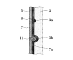
このようにして形成された接着剤層7の表面には凹みが形成される場合がある。この凹みは、主としてウェブ面の孔食に起因するものである。すなわち、図2に示すように、ケレンを行った後のウェブ3の表面には孔食の成長度合いによって大小多数の凹み3a,3bがあり、小さい凹み3aに関しては、エポキシ樹脂塗料をウェブ面の凹み3aに充填させるように塗布してエポキシ樹脂層5を形成することにより、接着剤層7の表面を平滑化することができる。一方、大きい凹み3bに関しては、エポキシ樹脂層5、プライマー層6、接着材層7によって凹み3bを消し去ることはできないため、接着剤層7の表面に凹み7aが現れる。接着剤層7の表面の凹み7aの大きさは、通常直径が1〜100mm程度である。
A dent may be formed on the surface of the
接着剤層の表面に上記凹み7aが確認できた場合には、この凹み7aにシーリング材を注入して凹み7aの内部にシーリング材層11を形成し、接着剤層7の表面を平滑化するのが好ましい。また、エポキシ樹脂層5を形成した段階で、エポキシ樹脂層5の表面に凹みが確認できた場合には、この凹みにエポキシ樹脂系シーリング材を注入してエポキシ樹脂層5の表面を平滑化した後に、プライマー層6および接着剤層7を形成してもよい。これにより、接着剤層7と後述する止水材8との接着強度を高めることができる。
シーリング材としては、例えば、東レ・ダウコーニング(株)製の「CF−5044」、コニシ(株)製の「MSシール」などのシリコン系材料などが挙げられる。エポキシ樹脂系シーリング材としては、例えば、コニシ(株)製の「E209」などのノンサグタイプのエポキシ樹脂系材料などが挙げられる。シーリング材やエポキシ樹脂系シーリング材を注入するには、例えば、ゴムヘラなどを用いればよい。
なお、接着剤層の表面を平滑化するとは、局所的な凹凸をなくし、なだらかにすることであり、具体的には局所的な凸部の高さまたは凹部の深さを表面から3mm以下、好ましくは1mm以下にすることである。
When the
Examples of the sealing material include silicon-based materials such as “CF-5044” manufactured by Toray Dow Corning Co., Ltd. and “MS Seal” manufactured by Konishi Co., Ltd. Examples of the epoxy resin sealing material include non-sag type epoxy resin materials such as “E209” manufactured by Konishi Co., Ltd. In order to inject the sealing material or the epoxy resin sealing material, for example, a rubber spatula or the like may be used.
In addition, smoothing the surface of the adhesive layer is to remove the local unevenness and smooth, specifically, the height of the local convex portion or the depth of the concave portion is 3 mm or less from the surface, Preferably, it is 1 mm or less.
次いで、対向するウェブ3,3面に止水材8を貼合する。止水材としては、例えば、ニッタ(株)製の伸縮追従性や寒冷地への適応力などに優れた乾式止水材「バリアレックス(登録商標)」、(株)川金コアテック製の「KMトップバリア」などの市販されている公知の乾式止水材、弾性シール材などが挙げられる。
ウェブ面に止水材を貼合する方法としては、例えば、図1(f)に示すように、上述した接着剤の塗布方法と同様にして止水材8の貼合面に接着剤を塗布して接着剤層7を形成した後、ウェブ3,3の遊間に位置合わせをして圧縮挿入すればよい。止水材8の貼合面に塗布する接着剤の塗布量は、100〜400g/m2、好ましくは200〜300g/m2であるのがよい。
さらに、図1(g)に示すように、鋼製伸縮装置1の対向するウェブ3,3の遊間に止水材8を設置し、止水材8を保持する支持金具9を取り付け、支持金具9に止水ゴム樋10を取り付ける。止水ゴム樋10としては、例えば、公知の止水ゴムパッキンなどが挙げられる。
Subsequently, the
As a method of bonding the water-stopping material to the web surface, for example, as shown in FIG. 1 (f), the adhesive is applied to the bonding surface of the water-stopping
Further, as shown in FIG. 1 (g), a
本発明の他の実施形態に係る道路橋伸縮装置用止水材の施工方法は、貼合工程において、プライマー層6を形成せずに、エポキシ樹脂層5上に接着剤層7を形成する他は、前記の実施形態と同様にして、図3に示すように実施することができる。
The construction method of the waterstop material for road bridge expansion and contraction device according to another embodiment of the present invention is that the
なお、本発明の道路橋伸縮装置用止水材の施工方法は、止水材の補修だけでなく、道路橋に設置する未使用の鋼製伸縮装置の対向するウェブの遊間に止水材を施工する場合にも適用可能であり、撤去工程(I)および洗浄工程(II)を行わない他は、前記の実施形態と同様にして実施することができる。 In addition, the construction method of the waterstop material for road bridge expansion and contraction device of the present invention is not only repairing the waterstop material, but also the waterstop material between the webs facing the unused steel expansion and contraction device installed on the road bridge. The present invention is also applicable to construction, and can be carried out in the same manner as in the above embodiment except that the removal step (I) and the cleaning step (II) are not performed.
<道路橋伸縮装置>
図4は、上記のようにして施行された本発明の一実施形態に係る道路橋伸縮装置1を示す断面図である。この鋼製伸縮装置1は、道路橋に形成された遊間の上部に設けられ、遊間の伸縮に応じて互いに噛み合うようにした一対のフェースプレート2,2と、該一対のフェースプレート2,2のそれぞれの下部に位置するウェブ3,3と、このウェブ3,3の遊間に設けられた止水材8とを備える。対向するウェブ面3,3には、エポキシ樹脂層5を介して、プライマー層6、接着剤層7がこの順に形成されている(図2参照)。さらに、止水材8は、ウェブ3,3の遊間に挿入され、かつ支持金具9により支持され、支持金具9には、止水ゴム樋10が取り付けられている。
<Road bridge telescopic device>
FIG. 4 is a cross-sectional view showing the road bridge telescopic device 1 according to one embodiment of the present invention, which is implemented as described above. This steel expansion / contraction device 1 is provided at the upper part of the gap formed on the road bridge, and a pair of
なお、本実施形態では、エポキシ樹脂層5上にプライマー層6、接着剤層7がこの順に形成されたものであるが、本発明はこれに限定されず、プライマー層6が形成されずに、エポキシ樹脂層5上に接着剤層7が形成されたものであってもよい。
In this embodiment, the
本発明では、対向するウェブ面にエポキシ樹脂層5を介して接着剤層7および止水材8がこの順に形成されているため塩分の影響によって接着剤層のウェブ側の接着力が損なわれない、または対向するウェブ面にエポキシ樹脂層5を介してプライマー層6、接着剤層7および止水材8がこの順に形成されているため、塩分の影響によってプライマー層の接着力が損なわれないので、止水材8がウェブ面から剥離しにくく、長期に亘って道路橋伸縮装置の止水機能を維持することができる。
In the present invention, since the
以下、実施例により本発明をより詳細に説明するが、本発明は、以下の実施例により限定されるものではない。 EXAMPLES Hereinafter, although an Example demonstrates this invention in detail, this invention is not limited by a following example.
試験体の破断強度の評価は以下の方法で行なった。
<破断強度測定>
(株)島津製作所製の万能引張試験機を用いて、各試験体を引張速度50mm/分にて上下に破断するまで拡張させ、試験体の破断強度を測定し、試験体の破断面の確認を行った。
The breaking strength of the test specimen was evaluated by the following method.
<Break strength measurement>
Using a universal tensile tester manufactured by Shimadzu Corporation, each test specimen was expanded at a tensile speed of 50 mm / min until it fractured up and down, the fracture strength of the specimen was measured, and the fracture surface of the specimen was confirmed. Went.
以下の実施例および比較例では、以下に示す鋼材、エポキシ樹脂塗料、プライマーおよび接着剤を用いた。
<鋼材>
鋼材として、一般構造用圧延鋼材SS400(JIS G 3101、サイズ:32mmφ×15mmt)を用いた。
<エポキシ樹脂塗料>
エポキシ樹脂塗料として、日本パーカライジング(株)製の「トリック(登録商標)1000」を用いた。
<プライマー>
プライマーとして、東レ・ダウコーニング(株)製のプライマー「D3(RF)」を用いた。
<接着剤>
接着剤として、東レ・ダウコーニング(株)製の「CF−5077」を用いた。
In the following examples and comparative examples, the following steel materials, epoxy resin paints, primers and adhesives were used.
<Steel>
As a steel material, a general structural rolled steel SS400 (JIS G 3101, size: 32 mmφ × 15 mmt) was used.
<Epoxy resin paint>
As an epoxy resin paint, “Trick (registered trademark) 1000” manufactured by Nippon Parkerizing Co., Ltd. was used.
<Primer>
A primer “D3 (RF)” manufactured by Toray Dow Corning Co., Ltd. was used as a primer.
<Adhesive>
As the adhesive, “CF-5077” manufactured by Toray Dow Corning Co., Ltd. was used.
(実施例1)
<試験体の作製>
鋼材を2枚用意し、それぞれの鋼材の表面にベルトサンダー等でケレンをして下地処理を行った後、以下の処理を行った。
(塩分付着工程)
下地処理を行った面に、濃度5重量%の食塩水を噴霧して付着させ、乾燥させた。試験体用鋼材に隣接させて設置した100×100の鋼材の表面塩分量をポータブル表面塩分計を用いて測定した。
(成膜工程)
鋼材の食塩水を付着させた面に、エポキシ樹脂塗料を刷毛を用いて300g/m2均一に塗布し、乾燥させてエポキシ樹脂層を形成した。なお、成膜工程は室温23度の環境下で実施した。
(貼合工程)
前記エポキシ樹脂層上にプライマーを刷毛を用いて50g/m2均一に塗布し、乾燥させてプライマー層を形成した後、このプライマー層上に接着剤を刷毛を用いて300g/m2均一に塗布し、12時間以上乾燥させて接着剤層を形成し、この接着剤層上にさらに接着剤を刷毛を用いて300g/m2均一に塗布して、すぐに2枚の鋼材を重ね合わせ、48時間以上乾燥させて試験体を得た。
(塩水処理工程)
この試験体を20重量%沸騰塩水中に1時間浸漬させて、劣化を促進させた。
Example 1
<Preparation of specimen>
Two steel materials were prepared, the surface of each steel material was cleaned with a belt sander or the like, and after the ground treatment, the following treatment was performed.
(Salting process)
A 5% strength by weight saline solution was sprayed on the surface that had been subjected to the base treatment, and dried. The surface salinity of a 100 × 100 steel material installed adjacent to the steel for the test specimen was measured using a portable surface salinity meter.
(Film formation process)
The surface adhered with saline steel, the epoxy resin coating with a brush is applied to 300 g / m 2 uniformly, to form an epoxy resin layer is dried. The film forming process was performed in an environment at room temperature of 23 degrees.
(Bonding process)
A primer is applied uniformly to the epoxy resin layer with a brush at 50 g / m 2 and dried to form a primer layer, and then an adhesive is applied onto the primer layer uniformly with a brush at a rate of 300 g / m 2. Then, it is dried for 12 hours or more to form an adhesive layer. Further, an adhesive is further uniformly applied on the adhesive layer with a brush at 300 g / m 2 , and two steel materials are immediately laminated. The test body was obtained by drying for more than an hour.
(Salt water treatment process)
This test specimen was immersed in 20% by weight boiling salt water for 1 hour to promote deterioration.
(実施例2)
塩分付着工程を行わなかった他は、実施例1と同様にして、試験体を得た。
(Example 2)
A test body was obtained in the same manner as in Example 1 except that the salt adhesion step was not performed.
(実施例3)
塩分付着工程および塩水処理工程を行わなかった他は、実施例1と同様にして、試験体を得た。
Example 3
A test body was obtained in the same manner as in Example 1 except that the salt adhesion step and the salt water treatment step were not performed.
(比較例1)
成膜工程を行わず、貼合工程において、下地処理を行った面にプライマーを塗布した他は、実施例1と同様にして、試験体を得た。
(Comparative Example 1)
A test body was obtained in the same manner as in Example 1 except that the film forming step was not performed and the primer was applied to the surface subjected to the base treatment in the bonding step.
(比較例2)
塩分付着工程および成膜工程を行わず、貼合工程において、下地処理を行った面にプライマーを塗布した他は、実施例1と同様にして、試験体を得た。
(Comparative Example 2)
A test specimen was obtained in the same manner as in Example 1 except that the salt adhesion step and the film formation step were not performed, and the primer was applied to the surface subjected to the base treatment in the bonding step.
(比較例3)
塩分付着工程、成膜工程および塩水処理工程を行わず、貼合工程において、下地処理を行った面にプライマーを塗布した他は、実施例1と同様にして、試験体を得た。
(Comparative Example 3)
A test specimen was obtained in the same manner as in Example 1 except that the primer was applied to the surface subjected to the ground treatment in the bonding step without performing the salt adhesion step, the film formation step and the salt water treatment step.
(比較例4)
塩分付着工程および塩水処理工程を行わず、成膜工程において、エポキシ樹脂層の代わりに、(株)ゼットアールシー・ジャパン製の常温亜鉛メッキ「ZRC」(スプレー)をスプレー塗布して、常温亜鉛メッキ膜を形成した他は、実施例1と同様にして、試験体を得た。
(Comparative Example 4)
Instead of the epoxy resin layer, spraying room temperature zinc plating “ZRC” (spray) manufactured by ZTRC Japan Co., Ltd. instead of the epoxy resin layer in the film forming process without performing the salt adhesion process and the salt water treatment process. A test body was obtained in the same manner as in Example 1 except that a film was formed.
(比較例5)
塩分付着工程および塩水処理工程を行わず、成膜工程において、エポキシ樹脂層の代わりに、旭化工(株)製のウレタン反応形プライマー「アサヒシールプライマー」を塗布してウレタン反応形プライマーを形成した後、シャープ化学工業(株)製のペイントウレタンを塗布し、東レ・ダウコーニング(株)製の「CF−5077」を均一に塗布した他は、実施例1と同様にして、試験体を得た。
(Comparative Example 5)
Instead of the epoxy resin layer, the urethane reactive primer “Asahi Seal Primer” manufactured by Asahi Kako Co., Ltd. was applied to form the urethane reactive primer in the film forming process without performing the salt adhesion process and the salt water treatment process. Thereafter, paint urethane manufactured by Sharp Chemical Industry Co., Ltd. was applied, and “CF-5077” manufactured by Toray Dow Corning Co., Ltd. was applied uniformly. It was.
(比較例6)
塩分付着工程、塩水処理工程を行わず、成膜工程において、エポキシ樹脂層の代わりに、関西ペイント(株)製のビニルブチラール系塗料エッチングプライマー「メタラクトH5」を均一に塗布して、エッチングプライマー層を形成した他は、実施例1と同様にして、試験体を得た。
(Comparative Example 6)
Applying the vinyl butyral paint etching primer “Metalac H5” made by Kansai Paint Co., Ltd. instead of the epoxy resin layer in the film-forming process without applying the salt adhesion process and the salt water treatment process, and etching primer layer A specimen was obtained in the same manner as in Example 1 except that was formed.
(比較例7)
塩分付着工程を行わず、成膜工程において、エポキシ樹脂層の代わりに、関西ペイント(株)製のビニルブチラール系塗料エッチングプライマー「メタラクトH5」を均一に塗布して、エッチングプライマー層を形成した他は、実施例1と同様にして、試験体を得た。
(Comparative Example 7)
In addition to forming an etching primer layer by uniformly applying the vinyl butyral paint etching primer “Metalac H5” manufactured by Kansai Paint Co., Ltd. instead of the epoxy resin layer in the film forming process without performing the salt adhesion process. Were obtained in the same manner as in Example 1.
各試験体について、破断強度の評価を行い、その結果を表1に示す。なお、表1の各試験体の(a)剥離形態、(b)剥離面積を下記のように評価した。
(a)剥離形態
PP剥離:塗料層(P)/プライマー層(P)間の剥離
PC剥離:プライマー層(P)/接着剤層(C)間の剥離
C材打破:接着剤層(C)の材破
なお、塗料層(P)とは、各実施例・比較例で用いられた表1に示す塗料により形成された層である、以下同じ。
(b)剥離面積
A:試験体の破断表面積の90〜100%が材料破断された接着剤面であり、それ以外の破断面は鋼板面、エポキシ樹脂面またはプライマー面の露出面であった。
B:試験体の破断表面積の10〜30%程度が鋼板面、エポキシ樹脂面またはプライマー露出面であり、それ以外の破断面は材料破断された接着剤面であった。
C:試験体の破断表面積の30〜50%程度が鋼板面、エポキシ樹脂面またはプライマー露出面であり、それ以外の破断面は材料破断された接着剤面であった。
D:試験体の破断表面積の50〜70%程度が鋼板面、エポキシ樹脂面またはプライマー露出面であり、それ以外の破断面は材料破断された接着剤面であった。
E:試験体の破断表面積の70%以上が鋼板面、エポキシ樹脂面またはプライマー露出面であり、それ以外の破断面は材料破断された接着剤面であった。
Each specimen was evaluated for breaking strength, and the results are shown in Table 1. In addition, (a) peeling form and (b) peeling area of each test body of Table 1 were evaluated as follows.
(A) Peeling PP peeling: peeling between paint layer (P) / primer layer (P) PC peeling: peeling between primer layer (P) / adhesive layer (C) Breaking C material: adhesive layer (C) In addition, a coating material layer (P) is a layer formed with the coating material shown in Table 1 used by each Example and the comparative example, and is the same hereafter.
(B) Peeling area A: 90 to 100% of the fracture surface area of the test specimen was the adhesive surface where the material was fractured, and the other fracture surface was the exposed surface of the steel plate surface, the epoxy resin surface or the primer surface.
B: About 10 to 30% of the fracture surface area of the test specimen was the steel plate surface, the epoxy resin surface or the primer exposed surface, and the other fractured surface was the adhesive surface with material fracture.
C: About 30 to 50% of the fracture surface area of the test specimen was a steel plate surface, an epoxy resin surface, or a primer exposed surface, and the other fracture surface was an adhesive surface with material fracture.
D: About 50 to 70% of the fracture surface area of the test specimen was a steel plate surface, an epoxy resin surface, or a primer exposed surface, and the other fracture surface was an adhesive surface with material fracture.
E: 70% or more of the fracture surface area of the test specimen was a steel plate surface, an epoxy resin surface, or a primer exposed surface, and the other fracture surface was an adhesive surface where the material was fractured.

1 鋼製伸縮装置
2 フェースプレート
3 ウェブ
4 取付金具
5 エポキシ樹脂層
6 プライマー層
7 接着剤層
8 支持金具
9 止水ゴム樋
10 シーリング材層
DESCRIPTION OF SYMBOLS 1 Steel expansion-
Claims (7)
(a)ウェブ面上にエポキシ樹脂層を形成する工程
(b)前記エポキシ樹脂層上に接着剤層を形成し、止水材を貼合する工程 A method for constructing a waterstop material for a road bridge expansion / contraction device in which a waterstop material is installed between the opposing webs of a steel expansion / contraction device, the method comprising the following steps: Construction method.
(A) The process of forming an epoxy resin layer on a web surface (b) The process of forming an adhesive bond layer on the said epoxy resin layer, and bonding a water stop material
(i)対向するウェブの遊間に設置されている既設止水材を撤去する工程
(ii)ウェブ面にケレンを行った後、ウェブ面を洗浄する工程 The construction method of the waterstop material for road bridge expansion-contraction apparatuses according to claim 1 or 2, wherein the following steps are performed before performing the steps (a) and (b).
(I) The process of removing the existing water stop material installed between the play of the opposing webs (ii) The process of cleaning the web surface after performing cleansing on the web surface
対向するウェブ面に、エポキシ樹脂層を介して、接着剤層および止水材がこの順に形成されていることを特徴とする道路橋伸縮装置。 A pair of face plates provided at the upper part of the play formed on the road bridge and engaged with each other according to the expansion and contraction of the play, a web positioned at the lower part of the pair of face plates, and the play between the webs A steel telescopic device provided with a water stop material provided,
A road bridge expansion and contraction device, wherein an adhesive layer and a water stop material are formed in this order on an opposing web surface via an epoxy resin layer.
Priority Applications (1)
| Application Number | Priority Date | Filing Date | Title |
|---|---|---|---|
| JP2012178521A JP6043121B2 (en) | 2012-08-10 | 2012-08-10 | Construction method of waterstop material for road bridge expansion and contraction device and road bridge expansion and contraction device |
Applications Claiming Priority (1)
| Application Number | Priority Date | Filing Date | Title |
|---|---|---|---|
| JP2012178521A JP6043121B2 (en) | 2012-08-10 | 2012-08-10 | Construction method of waterstop material for road bridge expansion and contraction device and road bridge expansion and contraction device |
Publications (2)
| Publication Number | Publication Date |
|---|---|
| JP2014034867A JP2014034867A (en) | 2014-02-24 |
| JP6043121B2 true JP6043121B2 (en) | 2016-12-14 |
Family
ID=50284017
Family Applications (1)
| Application Number | Title | Priority Date | Filing Date |
|---|---|---|---|
| JP2012178521A Active JP6043121B2 (en) | 2012-08-10 | 2012-08-10 | Construction method of waterstop material for road bridge expansion and contraction device and road bridge expansion and contraction device |
Country Status (1)
| Country | Link |
|---|---|
| JP (1) | JP6043121B2 (en) |
Family Cites Families (4)
| Publication number | Priority date | Publication date | Assignee | Title |
|---|---|---|---|---|
| JPS6213602A (en) * | 1985-05-15 | 1987-01-22 | 阪神高速道路公団 | Non-drainage construction method of extensible apparatus made of steel |
| JPH07150506A (en) * | 1993-11-30 | 1995-06-13 | Motonosuke Arai | Road joint expansion device |
| JP2002363912A (en) * | 2001-06-06 | 2002-12-18 | Nitta Ind Corp | Joint structure for bridge |
| JP5294672B2 (en) * | 2008-03-28 | 2013-09-18 | 北海道旅客鉄道株式会社 | Method for joining bridges |
-
2012
- 2012-08-10 JP JP2012178521A patent/JP6043121B2/en active Active
Also Published As
| Publication number | Publication date |
|---|---|
| JP2014034867A (en) | 2014-02-24 |
Similar Documents
| Publication | Publication Date | Title |
|---|---|---|
| CN105149195A (en) | Paint construction technology of novel steel structure | |
| KR20160125654A (en) | Repairing Method for Crack of Concrete Structure | |
| JP7194395B2 (en) | Joint repair method | |
| JP6043121B2 (en) | Construction method of waterstop material for road bridge expansion and contraction device and road bridge expansion and contraction device | |
| CN101761242B (en) | Lossless and reversible repairing method of damaged hard basic layer | |
| KR102076259B1 (en) | A repair unit for repairing a pop out site or a crack site of a concrete building, and a repair or pop out site using the repair unit | |
| KR100734176B1 (en) | The urethane coating waterproof method of the roof and the ground of building using by the embossment spray coating system that makes embossing layers | |
| RU2138752C1 (en) | Coat for tube sheets and cooling tubes of heat exchangers and method: of obtaining coat | |
| KR101376090B1 (en) | Repair method for concrete structure and automatic machine for the repair method | |
| JPH05214701A (en) | Coated rail | |
| JP2006064166A (en) | Oil leakage point sealing method | |
| KR101559573B1 (en) | Functional composition for steel material coating and steel material coating method using the same | |
| RU2242571C1 (en) | Method and means for repairing and filling up interpanel joints | |
| JP3106388B2 (en) | Stone finishing method and structure of steel base or steel base with old coating | |
| JP6781230B2 (en) | Water tank paint repair method | |
| KR102462451B1 (en) | A crack repairing and waterproofing method of concrete structure using spunlace non-woven fabric sheet | |
| JP6611213B1 (en) | Water tank paint repair method | |
| RU2226234C1 (en) | Method for recovering interpanel joints and organizing protection of wall structures, method for sealing interpanel joints and organizing protection of wall structures, as well as assembly for sealing interpanel joint of wall | |
| JP7144893B1 (en) | Kitchen floor renewal method | |
| JP6936708B2 (en) | Sealing structure and sealing method | |
| KR101165004B1 (en) | surface-coating construction and method of a drain pipe | |
| TWI680246B (en) | A method of sealing a metal seam | |
| KR101455274B1 (en) | Anticorrosion material and constructing method thereof and anticorrosion structure | |
| JP2004244652A (en) | Corrosion preventive method of steel structure, corrosion preventive sheet, and corrosion-proof steel structure | |
| JP2019108768A (en) | Joint reinforcement method |
Legal Events
| Date | Code | Title | Description |
|---|---|---|---|
| A621 | Written request for application examination |
Free format text: JAPANESE INTERMEDIATE CODE: A621 Effective date: 20150724 |
|
| A977 | Report on retrieval |
Free format text: JAPANESE INTERMEDIATE CODE: A971007 Effective date: 20160526 |
|
| A131 | Notification of reasons for refusal |
Free format text: JAPANESE INTERMEDIATE CODE: A131 Effective date: 20160607 |
|
| A521 | Written amendment |
Free format text: JAPANESE INTERMEDIATE CODE: A523 Effective date: 20160726 |
|
| TRDD | Decision of grant or rejection written | ||
| A01 | Written decision to grant a patent or to grant a registration (utility model) |
Free format text: JAPANESE INTERMEDIATE CODE: A01 Effective date: 20161101 |
|
| A61 | First payment of annual fees (during grant procedure) |
Free format text: JAPANESE INTERMEDIATE CODE: A61 Effective date: 20161111 |
|
| R150 | Certificate of patent or registration of utility model |
Ref document number: 6043121 Country of ref document: JP Free format text: JAPANESE INTERMEDIATE CODE: R150 |