JP6043045B2 - Vehicle control system - Google Patents
Vehicle control system Download PDFInfo
- Publication number
- JP6043045B2 JP6043045B2 JP2010146947A JP2010146947A JP6043045B2 JP 6043045 B2 JP6043045 B2 JP 6043045B2 JP 2010146947 A JP2010146947 A JP 2010146947A JP 2010146947 A JP2010146947 A JP 2010146947A JP 6043045 B2 JP6043045 B2 JP 6043045B2
- Authority
- JP
- Japan
- Prior art keywords
- current
- current sensor
- phase
- inverter circuit
- vehicle
- Prior art date
- Legal status (The legal status is an assumption and is not a legal conclusion. Google has not performed a legal analysis and makes no representation as to the accuracy of the status listed.)
- Active
Links
Images


Classifications
-
- H—ELECTRICITY
- H02—GENERATION; CONVERSION OR DISTRIBUTION OF ELECTRIC POWER
- H02H—EMERGENCY PROTECTIVE CIRCUIT ARRANGEMENTS
- H02H7/00—Emergency protective circuit arrangements specially adapted for specific types of electric machines or apparatus or for sectionalised protection of cable or line systems, and effecting automatic switching in the event of an undesired change from normal working conditions
- H02H7/08—Emergency protective circuit arrangements specially adapted for specific types of electric machines or apparatus or for sectionalised protection of cable or line systems, and effecting automatic switching in the event of an undesired change from normal working conditions for dynamo-electric motors
- H02H7/0805—Emergency protective circuit arrangements specially adapted for specific types of electric machines or apparatus or for sectionalised protection of cable or line systems, and effecting automatic switching in the event of an undesired change from normal working conditions for dynamo-electric motors for synchronous motors
-
- B—PERFORMING OPERATIONS; TRANSPORTING
- B60—VEHICLES IN GENERAL
- B60L—PROPULSION OF ELECTRICALLY-PROPELLED VEHICLES; SUPPLYING ELECTRIC POWER FOR AUXILIARY EQUIPMENT OF ELECTRICALLY-PROPELLED VEHICLES; ELECTRODYNAMIC BRAKE SYSTEMS FOR VEHICLES IN GENERAL; MAGNETIC SUSPENSION OR LEVITATION FOR VEHICLES; MONITORING OPERATING VARIABLES OF ELECTRICALLY-PROPELLED VEHICLES; ELECTRIC SAFETY DEVICES FOR ELECTRICALLY-PROPELLED VEHICLES
- B60L3/00—Electric devices on electrically-propelled vehicles for safety purposes; Monitoring operating variables, e.g. speed, deceleration or energy consumption
- B60L3/0023—Detecting, eliminating, remedying or compensating for drive train abnormalities, e.g. failures within the drive train
- B60L3/003—Detecting, eliminating, remedying or compensating for drive train abnormalities, e.g. failures within the drive train relating to inverters
-
- B—PERFORMING OPERATIONS; TRANSPORTING
- B60—VEHICLES IN GENERAL
- B60L—PROPULSION OF ELECTRICALLY-PROPELLED VEHICLES; SUPPLYING ELECTRIC POWER FOR AUXILIARY EQUIPMENT OF ELECTRICALLY-PROPELLED VEHICLES; ELECTRODYNAMIC BRAKE SYSTEMS FOR VEHICLES IN GENERAL; MAGNETIC SUSPENSION OR LEVITATION FOR VEHICLES; MONITORING OPERATING VARIABLES OF ELECTRICALLY-PROPELLED VEHICLES; ELECTRIC SAFETY DEVICES FOR ELECTRICALLY-PROPELLED VEHICLES
- B60L3/00—Electric devices on electrically-propelled vehicles for safety purposes; Monitoring operating variables, e.g. speed, deceleration or energy consumption
- B60L3/0023—Detecting, eliminating, remedying or compensating for drive train abnormalities, e.g. failures within the drive train
- B60L3/0069—Detecting, eliminating, remedying or compensating for drive train abnormalities, e.g. failures within the drive train relating to the isolation, e.g. ground fault or leak current
-
- B—PERFORMING OPERATIONS; TRANSPORTING
- B60—VEHICLES IN GENERAL
- B60L—PROPULSION OF ELECTRICALLY-PROPELLED VEHICLES; SUPPLYING ELECTRIC POWER FOR AUXILIARY EQUIPMENT OF ELECTRICALLY-PROPELLED VEHICLES; ELECTRODYNAMIC BRAKE SYSTEMS FOR VEHICLES IN GENERAL; MAGNETIC SUSPENSION OR LEVITATION FOR VEHICLES; MONITORING OPERATING VARIABLES OF ELECTRICALLY-PROPELLED VEHICLES; ELECTRIC SAFETY DEVICES FOR ELECTRICALLY-PROPELLED VEHICLES
- B60L3/00—Electric devices on electrically-propelled vehicles for safety purposes; Monitoring operating variables, e.g. speed, deceleration or energy consumption
- B60L3/04—Cutting off the power supply under fault conditions
-
- H—ELECTRICITY
- H02—GENERATION; CONVERSION OR DISTRIBUTION OF ELECTRIC POWER
- H02H—EMERGENCY PROTECTIVE CIRCUIT ARRANGEMENTS
- H02H7/00—Emergency protective circuit arrangements specially adapted for specific types of electric machines or apparatus or for sectionalised protection of cable or line systems, and effecting automatic switching in the event of an undesired change from normal working conditions
- H02H7/08—Emergency protective circuit arrangements specially adapted for specific types of electric machines or apparatus or for sectionalised protection of cable or line systems, and effecting automatic switching in the event of an undesired change from normal working conditions for dynamo-electric motors
- H02H7/0833—Emergency protective circuit arrangements specially adapted for specific types of electric machines or apparatus or for sectionalised protection of cable or line systems, and effecting automatic switching in the event of an undesired change from normal working conditions for dynamo-electric motors for electric motors with control arrangements
- H02H7/0838—Emergency protective circuit arrangements specially adapted for specific types of electric machines or apparatus or for sectionalised protection of cable or line systems, and effecting automatic switching in the event of an undesired change from normal working conditions for dynamo-electric motors for electric motors with control arrangements with H-bridge circuit
-
- H—ELECTRICITY
- H02—GENERATION; CONVERSION OR DISTRIBUTION OF ELECTRIC POWER
- H02H—EMERGENCY PROTECTIVE CIRCUIT ARRANGEMENTS
- H02H7/00—Emergency protective circuit arrangements specially adapted for specific types of electric machines or apparatus or for sectionalised protection of cable or line systems, and effecting automatic switching in the event of an undesired change from normal working conditions
- H02H7/10—Emergency protective circuit arrangements specially adapted for specific types of electric machines or apparatus or for sectionalised protection of cable or line systems, and effecting automatic switching in the event of an undesired change from normal working conditions for converters; for rectifiers
- H02H7/12—Emergency protective circuit arrangements specially adapted for specific types of electric machines or apparatus or for sectionalised protection of cable or line systems, and effecting automatic switching in the event of an undesired change from normal working conditions for converters; for rectifiers for static converters or rectifiers
- H02H7/122—Emergency protective circuit arrangements specially adapted for specific types of electric machines or apparatus or for sectionalised protection of cable or line systems, and effecting automatic switching in the event of an undesired change from normal working conditions for converters; for rectifiers for static converters or rectifiers for inverters, i.e. dc/ac converters
- H02H7/1227—Emergency protective circuit arrangements specially adapted for specific types of electric machines or apparatus or for sectionalised protection of cable or line systems, and effecting automatic switching in the event of an undesired change from normal working conditions for converters; for rectifiers for static converters or rectifiers for inverters, i.e. dc/ac converters responsive to abnormalities in the output circuit, e.g. short circuit
-
- B—PERFORMING OPERATIONS; TRANSPORTING
- B60—VEHICLES IN GENERAL
- B60L—PROPULSION OF ELECTRICALLY-PROPELLED VEHICLES; SUPPLYING ELECTRIC POWER FOR AUXILIARY EQUIPMENT OF ELECTRICALLY-PROPELLED VEHICLES; ELECTRODYNAMIC BRAKE SYSTEMS FOR VEHICLES IN GENERAL; MAGNETIC SUSPENSION OR LEVITATION FOR VEHICLES; MONITORING OPERATING VARIABLES OF ELECTRICALLY-PROPELLED VEHICLES; ELECTRIC SAFETY DEVICES FOR ELECTRICALLY-PROPELLED VEHICLES
- B60L2200/00—Type of vehicles
- B60L2200/26—Rail vehicles
-
- B—PERFORMING OPERATIONS; TRANSPORTING
- B60—VEHICLES IN GENERAL
- B60L—PROPULSION OF ELECTRICALLY-PROPELLED VEHICLES; SUPPLYING ELECTRIC POWER FOR AUXILIARY EQUIPMENT OF ELECTRICALLY-PROPELLED VEHICLES; ELECTRODYNAMIC BRAKE SYSTEMS FOR VEHICLES IN GENERAL; MAGNETIC SUSPENSION OR LEVITATION FOR VEHICLES; MONITORING OPERATING VARIABLES OF ELECTRICALLY-PROPELLED VEHICLES; ELECTRIC SAFETY DEVICES FOR ELECTRICALLY-PROPELLED VEHICLES
- B60L2220/00—Electrical machine types; Structures or applications thereof
- B60L2220/10—Electrical machine types
- B60L2220/14—Synchronous machines
-
- H—ELECTRICITY
- H02—GENERATION; CONVERSION OR DISTRIBUTION OF ELECTRIC POWER
- H02H—EMERGENCY PROTECTIVE CIRCUIT ARRANGEMENTS
- H02H3/00—Emergency protective circuit arrangements for automatic disconnection directly responsive to an undesired change from normal electric working condition with or without subsequent reconnection ; integrated protection
- H02H3/08—Emergency protective circuit arrangements for automatic disconnection directly responsive to an undesired change from normal electric working condition with or without subsequent reconnection ; integrated protection responsive to excess current
- H02H3/083—Emergency protective circuit arrangements for automatic disconnection directly responsive to an undesired change from normal electric working condition with or without subsequent reconnection ; integrated protection responsive to excess current for three-phase systems
-
- H—ELECTRICITY
- H02—GENERATION; CONVERSION OR DISTRIBUTION OF ELECTRIC POWER
- H02H—EMERGENCY PROTECTIVE CIRCUIT ARRANGEMENTS
- H02H3/00—Emergency protective circuit arrangements for automatic disconnection directly responsive to an undesired change from normal electric working condition with or without subsequent reconnection ; integrated protection
- H02H3/16—Emergency protective circuit arrangements for automatic disconnection directly responsive to an undesired change from normal electric working condition with or without subsequent reconnection ; integrated protection responsive to fault current to earth, frame or mass
- H02H3/162—Emergency protective circuit arrangements for automatic disconnection directly responsive to an undesired change from normal electric working condition with or without subsequent reconnection ; integrated protection responsive to fault current to earth, frame or mass for ac systems
- H02H3/165—Emergency protective circuit arrangements for automatic disconnection directly responsive to an undesired change from normal electric working condition with or without subsequent reconnection ; integrated protection responsive to fault current to earth, frame or mass for ac systems for three-phase systems
-
- H—ELECTRICITY
- H02—GENERATION; CONVERSION OR DISTRIBUTION OF ELECTRIC POWER
- H02H—EMERGENCY PROTECTIVE CIRCUIT ARRANGEMENTS
- H02H3/00—Emergency protective circuit arrangements for automatic disconnection directly responsive to an undesired change from normal electric working condition with or without subsequent reconnection ; integrated protection
- H02H3/26—Emergency protective circuit arrangements for automatic disconnection directly responsive to an undesired change from normal electric working condition with or without subsequent reconnection ; integrated protection responsive to difference between voltages or between currents; responsive to phase angle between voltages or between currents
- H02H3/265—Emergency protective circuit arrangements for automatic disconnection directly responsive to an undesired change from normal electric working condition with or without subsequent reconnection ; integrated protection responsive to difference between voltages or between currents; responsive to phase angle between voltages or between currents responsive to phase angle between voltages or between currents
Landscapes
- Engineering & Computer Science (AREA)
- Power Engineering (AREA)
- Life Sciences & Earth Sciences (AREA)
- Sustainable Development (AREA)
- Sustainable Energy (AREA)
- Transportation (AREA)
- Mechanical Engineering (AREA)
- Control Of Ac Motors In General (AREA)
- Electric Propulsion And Braking For Vehicles (AREA)
Description
本実施形態は、車両用制御システムに関する。 The present embodiment relates to a vehicle control system.
従来、鉄道車両の駆動システムとしては誘導電動機が広く用いられてきた。しかし近年は、省エネの観点から効率の高い永久磁石同期電動機を用いた駆動システムが広がりつつある。永久磁石同期電動機は回転子に磁石が内蔵されているため自ら磁界を発生させることができ、誘導電動機のよう回転子に電流を流す必要がない。従って、回転子での電流損失や、電流損失により熱の発生などが存在しないことから、一般に永久磁石同期電動機は誘導電動機よりも効率が高いとされている。 Conventionally, induction motors have been widely used as drive systems for railway vehicles. However, in recent years, drive systems using permanent magnet synchronous motors with high efficiency from the viewpoint of energy saving are spreading. Since the permanent magnet synchronous motor has a magnet built in the rotor, it can generate a magnetic field by itself and does not require a current to flow through the rotor unlike an induction motor. Accordingly, since there is no current loss in the rotor and no heat is generated due to the current loss, the permanent magnet synchronous motor is generally considered to be more efficient than the induction motor.
一方で、永久磁石同期電動機は回転子に磁石が内蔵されていることによる弊害もある。これは、力行や回生などの制御中でなくても、走行中には回転速度に比例した誘起電圧を発生させてしまうことである。特に、高速回転中では誘起電圧が制御装置であるインバータ回路の直流電圧を超え、自動的に回生動作が始まってしまう。そのため、惰性走行時でも意図的に磁束を弱める電流を流し続けることで誘起電圧を抑制する必要がある。さらには、インバータ回路と永久磁石同期電動機間で短絡事故や地絡事故が発生した場合には、永久磁石同期電動機が電源とした事故回路が形成されるなど、誘導電動機では考えられなかった問題も多く存在する。こういった永久磁石同期電動機、特有の事故に配慮し、インバータ回路と永久磁石同期電動機の間に接触器を接続し、インバータ回路を保護する事例も見られる。 On the other hand, the permanent magnet synchronous motor also has an adverse effect due to the magnet built in the rotor. This means that an induced voltage proportional to the rotational speed is generated during traveling even if the power running or regeneration is not being controlled. In particular, during high-speed rotation, the induced voltage exceeds the DC voltage of the inverter circuit that is the control device, and the regenerative operation starts automatically. Therefore, it is necessary to suppress the induced voltage by continuing to flow a current that intentionally weakens the magnetic flux even during inertial running. Furthermore, in the event of a short circuit accident or a ground fault between the inverter circuit and the permanent magnet synchronous motor, there is a problem that could not be considered with an induction motor, such as an accident circuit that uses the permanent magnet synchronous motor as a power source. There are many. Considering such a permanent magnet synchronous motor and a peculiar accident, there are cases where a contactor is connected between the inverter circuit and the permanent magnet synchronous motor to protect the inverter circuit.
車両用制御システムにおいて、しばしば電動機とその電動機のインバータ回路が異なる車両に設置されている場合がある。このような場合、車両間を繋ぐ配線が必要となる。この部分の配線は、車両間の動作を考慮して柔軟に可動できるように電線を用いることが一般的である。しかしながら、電線が車両の動作に合わせて動く際に、この電線部分で混触や地絡が発生するという問題があった。 In a vehicle control system, an electric motor and an inverter circuit of the electric motor are often installed in different vehicles. In such a case, the wiring which connects between vehicles is needed. As for the wiring of this part, it is common to use an electric wire so that it can move flexibly in consideration of the operation between vehicles. However, when the electric wire moves in accordance with the operation of the vehicle, there is a problem that an incompatibility or a ground fault occurs in the electric wire portion.
本発明は、上記問題点を解決するためになされたものであり、車両間を繋ぐ配線で混触や地絡が発生した場合でも、インバータ回路の保護を可能とする車両用制御システムを提供することを目的とする。 The present invention has been made to solve the above-described problems, and provides a vehicle control system that enables protection of an inverter circuit even when a contact or a ground fault occurs in wiring connecting vehicles. With the goal.
上記を解決するための車両用制御システムは、第1の車両に設置されたインバータ回路と、第2の車両に設置された永久磁石同期電動機と、前記インバータ回路と前記永久磁石同期電動機間であって、前記インバータ回路からの電力を中継するために前記第2の車両とこの第2の車両に隣接する車両との間に設けられた渡り配線と、前記インバータ回路と前記永久磁石同期電動機間に接続される電流センサと、前記渡り配線と前記永久磁石同期電動機間に接続され、電気的開放及び投入を可能とする接触器と、前記電流センサが検出した電流値を受け取り、この電流値に基づいて異常を検出するとともに、異常が検出された場合に前記接触器が開放されるように制御する制御部とを有することを特徴としている。 The vehicle control system for solving the above, an inverter circuit which is installed in the first vehicle, and a permanent magnet synchronous motor installed in the second vehicle, between the inverter circuit and the permanent magnet synchronous motor there are a interconnectors provided between the vehicle adjacent to the second vehicle and the second vehicle to relay power from the inverter circuit, said inverter circuit and said permanent magnet synchronous motor A current sensor connected in between, a contactor connected between the crossover wiring and the permanent magnet synchronous motor, enabling electrical opening and closing, and a current value detected by the current sensor; And a controller for controlling the contactor to be opened when an abnormality is detected.
本発明によれば、インバータ回路の保護が可能であるため、鉄道車両の安全な走行を提供することができる。 According to the present invention, since the inverter circuit can be protected, safe traveling of the railway vehicle can be provided.
以下、本発明の実施形態を図面を参照して説明する。 Hereinafter, embodiments of the present invention will be described with reference to the drawings.
(第1の実施形態)
図1を参照して本実施形態の構成について説明する。
(First embodiment)
The configuration of this embodiment will be described with reference to FIG.
(構成)
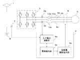
図1は、パンタグラフ1、インバータ回路2、第1電流センサ3a、第2電流センサ3b、U相線4a、V相線4b、W相線4c、接触器5、永久磁石同期電動機6、第3電流センサ7、接地8、制御部9、入力電流演算部9a、異常検知部9b、接触器開放指令部9c、U相渡り配線10a、V相渡り配線10b、W相渡り配線10cで構成される。
(Constitution)
1 shows a
インバータ回路2の直流側では、パンタグラフ1及び接地8が接続される。第3電流センサ7はインバータ回路2と接地8の間に接続される。インバータ回路3の交流側では、U相線4a上の第1電流センサ3a、U相渡り配線10a、接触器5を介してインバータ回路2と永久磁石同期電動機6が接続される。また、V相線4b上のV相渡り配線10b、接触器5を介してインバータ回路2と永久磁石同期電動機6が接続される。また、W相線4c上の第2電流センサ3b、W相渡り配線10c、接触器5を介してインバータ回路2と永久磁石同期電動機6が接続される。
On the DC side of the
制御部9は、第1電流センサ3a、第2電流センサ3b、第3電流センサ7、接触器5と接続されている。制御部9に内蔵される入力電流演算部9aは、第1電流センサ3a、第2電流センサ3b、第3電流センサ7、異常検知部9bと接続される。異常検知部9bは、入力電流演算部9a、接触器開放司令部9cと接続される。接触器開放指令部9cは、異常検知部9bと接触器5と接続される。
The controller 9 is connected to the first
(作用)
次に本実施形態の作用について説明する。架線電力はパンタグラフ1を介してインバータ回路2へ供給される。インバータ回路2では、入力電力を永久磁石同期電動機6が駆動可能な交流電力に変換する。変換された交流電力のU相電流は第1電流センサ3a(交流電流センサ)によって検出され、通常投入状態になっている接触器5を通って永久磁石同期電動機6へ流れる。W相電流も同様である。また第3電流センサ(直流電流センサ)は、インバータ回路2の直流側で帰線電流を検出する。
(Function)
Next, the operation of this embodiment will be described. The overhead line power is supplied to the
このように第1電流センサ乃至第3電流センサによって検出された電流を制御部9の入力電流演算部9aで演算する。異常検知部9bでは、後述する異常検知手段に基づき、演算された電流値をもとに異常があるかどうかを判定する。異常検知部9bで異常が判定された場合は、接触器開放指令部9cの指令により接触器9cが開放される。
Thus, the current detected by the first to third current sensors is calculated by the input
次に図2を用いて本実施形態の異常検知手段について説明する。図2(a)に示すように、第1電流センサ3a、第2電流センサ3bによってU相線4aの電流(Iu)、W相線4cの電流(Iw)が検出される(S2)。検出されたU相線4aの電流(Iu)及びW相線4cの電流(Iw)に基づき、制御部9の入力電流演算部9aでU相線4aの電流(Iu)、V相線4bの電流(Iv)、W相線4cの電流(Iw)のそれぞれ位相を演算する。入力電流演算部9aで演算した(Iu)、(Iv)、(Iw)は異常検知部9bに入力される。異常検知部9bでは、演算された(Iu)の位相から(Iw)の位相が240°ずれているかどうかを判断し(S3)、240°ずれている場合には再度、第1電流センサ3aと第2電流センサ3bでの電流検出を行なう。また、この異常検知手段において、異常の判定は、(Iu)の位相から(Iv)の位相が120°ずれているかどうか、または、(Iv)の位相から(Iw)の位相が120°ずれているかどうかによって判定することも可能である。
Next, the abnormality detection means of this embodiment will be described with reference to FIG. As shown in FIG. 2A, the current (Iu) of the
一方、240°のずれが生じていない場合、U相渡り配線10a、V相渡り配線10b、W相渡り配線10cのうち2つの配線間において2相短絡が生じている(S4)とし、異常検知部9bは接触器開放指令部9cへ接触器を開放するための異常信号を入力し、接触器開放指令部9cは接触器5の開放を実行する(S5)。
On the other hand, if there is no 240 ° shift, it is assumed that a two-phase short circuit has occurred between two of the U-phase
次に図2(b)を用いて3相短絡の場合について説明する。第1電流センサ3aはU相線4aの電流(Iu)を検出している。第2電流センサ3bは、W相線4cの電流(Iw)を検出している(S12)。検出されたU相線4aの電流(Iu)及びW相線4cの電流(Iw)に基づき、制御部9の入力電流演算部9aでU相線4aの電流(Iu)、V相線4bの電流(Iv)、W相線4cの電流(Iw)のそれぞれ電流値を演算する。入力電流演算部9aで演算した(Iu)、(Iv)、(Iw)は異常検知部9bに入力される。異常検知部9bでは、演算された(Iu)、(Iw)が所定値(α)を超過していないかを判断する(S13)。超過していない場合には再度、第1電流センサ3aと第2電流センサ3bでの電流検出を行なう。
Next, the case of a three-phase short circuit will be described with reference to FIG. The first
一方、超過している場合は場合、U相渡り配線10a、V相渡り配線10b、W相渡り配線10cの配線間において3相短絡が生じている(S14)とし、異常検知部9bは接触器開放指令部9cへ接触器を開放するための異常信号を入力し、接触器開放指令部9cは接触器5の開放を実行する(S15)。
On the other hand, if it exceeds, it is assumed that a three-phase short circuit has occurred between the
次に図2(c)を用いて地絡事故の場合について説明する。第3電流センサ7はインバータ回路2の直流帰線側の電流(IAC)を検出している(S22)。検出された直流帰線側の電流(IAC)は、制御部9の入力電流演算部9aへ入力される。電流(IAC)は、入力電流演算部9aから異常検知部9bへ入力される。異常検知部9bでは、電流(IAC)が所定値(β)を超過していないかを判断する(S23)。超過していない場合には再度、第3電流センサ7での電流検出を行なう。
Next, the case of a ground fault will be described with reference to FIG. The third current sensor 7 detects a current (IAC) on the DC return side of the inverter circuit 2 (S22). The detected DC return current (IAC) is input to the input
一方、超過している場合は場合、U相渡り配線10a、V相渡り配線10b、W相渡り配線10cの配線間のいずれかにおいて地絡事故が生じている(S24)とし、異常検知部9bは接触器開放指令部9cへ接触器を開放するための異常信号を入力し、接触器開放指令部9cは接触器5の開放を実行する(S25)。
On the other hand, if it exceeds, it is assumed that a ground fault has occurred in any of the
(効果)
本実施形態の効果について図3を用いて説明する。第1車両11にインバータ回路2が設置され、第2車両12には永久磁石同期電動機6と接触器5が設置されている。
(effect)
The effect of this embodiment will be described with reference to FIG. The
例えば、接触器5が渡り線10a、10b、10cとインバータ回路2の間に設置されている状態で渡り線10a、10bで短絡が起きた場合、永久磁石同期電動機6から出力される電流はU相線4aから渡り線10a、渡り線10bを介してV相線4bを通って永久磁石動機電動機6に回帰する事故回路が生じてしまう。このような事故回路が生じると、鉄道車両の走行に支障をきたす恐れがある。しかしながら、本実施形態では、U相渡り配線10a、V相渡り配線10b、W相渡り配線10cと永久磁石同期電動機6の間に接触器5を設けているため、図3に示すように、U相渡り配線10a、V相渡り配線10b間で短絡が起こった場合でも、接触器5を開放することで、永久磁石同期電動機6に短絡電流が流れることを防止することが可能となる。
For example, when a short circuit occurs in the connecting
このような本実施形態の構成によると、車両間を繋ぐ配線で混触や地絡が発生した場合でも、インバータ回路の保護を可能とする車両用制御システムを提供すること可能となる。 According to such a configuration of the present embodiment, it is possible to provide a vehicle control system that can protect the inverter circuit even when a contact or a ground fault occurs in the wiring connecting the vehicles.
1 パンタグタフ
2 インバータ回路
3 電流センサ
3a 第1電流センサ
3b 第2電流センサ
4 三相線
4a U相線
4b V相線
4c W相線
5 接触器
6 永久磁石同期電動機
7 第3電流センサ
8 接地
9 制御部
9a 入力電流演算部
9b 異常検知部
9c 接触器開放司令部
10a U相渡り配線
10b V相渡り配線
10c W相渡り配線
11 第1車両
12 第2車両
DESCRIPTION OF
Claims (6)
第2の車両に設置された永久磁石同期電動機と、
前記インバータ回路と前記永久磁石同期電動機間であって、前記インバータ回路からの電力を中継するために前記第2の車両とこの第2の車両に隣接する車両との間に設けられた渡り配線と、
前記インバータ回路と前記永久磁石同期電動機間に接続される電流センサと、
前記渡り配線と前記永久磁石同期電動機間に接続され、電気的開放及び投入を可能とする接触器と、
前記電流センサが検出した電流値を受け取り、この電流値に基づいて異常を検出するとともに、異常が検出された場合に前記接触器が開放されるように制御する制御部と
を有する車両用制御システム。 An inverter circuit installed in the first vehicle;
A permanent magnet synchronous motor installed in a second vehicle;
A between the inverter circuit and the permanent magnet synchronous motor, interconnectors provided between the vehicle adjacent to the second vehicle and the second vehicle to relay power from the inverter circuit When,
A current sensor connected between the inverter circuit and the permanent magnet synchronous motor,
A contactor connected between the crossover wiring and the permanent magnet synchronous motor, allowing electrical opening and closing;
A vehicle control system that receives a current value detected by the current sensor, detects an abnormality based on the current value, and controls the contactor to be opened when the abnormality is detected. .
Priority Applications (6)
| Application Number | Priority Date | Filing Date | Title |
|---|---|---|---|
| JP2010146947A JP6043045B2 (en) | 2010-06-28 | 2010-06-28 | Vehicle control system |
| US13/164,846 US8559143B2 (en) | 2010-06-28 | 2011-06-21 | Vehicle control system |
| PCT/JP2011/065240 WO2012002554A1 (en) | 2010-06-28 | 2011-06-27 | Vehicle control system |
| CN201180014928.XA CN102802997B (en) | 2010-06-28 | 2011-06-27 | Vehicle control system |
| EP11801016.4A EP2585335A4 (en) | 2010-06-28 | 2011-06-27 | Vehicle control system |
| HK13105557.9A HK1178496A1 (en) | 2010-06-28 | 2013-05-09 | Vehicle control system |
Applications Claiming Priority (1)
| Application Number | Priority Date | Filing Date | Title |
|---|---|---|---|
| JP2010146947A JP6043045B2 (en) | 2010-06-28 | 2010-06-28 | Vehicle control system |
Publications (3)
| Publication Number | Publication Date |
|---|---|
| JP2012010568A JP2012010568A (en) | 2012-01-12 |
| JP2012010568A5 JP2012010568A5 (en) | 2013-05-02 |
| JP6043045B2 true JP6043045B2 (en) | 2016-12-14 |
Family
ID=45351895
Family Applications (1)
| Application Number | Title | Priority Date | Filing Date |
|---|---|---|---|
| JP2010146947A Active JP6043045B2 (en) | 2010-06-28 | 2010-06-28 | Vehicle control system |
Country Status (6)
| Country | Link |
|---|---|
| US (1) | US8559143B2 (en) |
| EP (1) | EP2585335A4 (en) |
| JP (1) | JP6043045B2 (en) |
| CN (1) | CN102802997B (en) |
| HK (1) | HK1178496A1 (en) |
| WO (1) | WO2012002554A1 (en) |
Families Citing this family (16)
| Publication number | Priority date | Publication date | Assignee | Title |
|---|---|---|---|---|
| ES2602809T3 (en) * | 2009-12-28 | 2017-02-22 | Mitsubishi Electric Corporation | AC motor drive control device |
| JP5835692B2 (en) * | 2011-11-30 | 2015-12-24 | 株式会社東芝 | Vehicle drive control device |
| FR2987705B1 (en) * | 2012-03-02 | 2016-11-25 | Alstom Transport Sa | SYNCHRONOUS ELECTRIC MACHINE SUPPLY CHAIN, ELECTRICAL TRACTION SYSTEM COMPRISING SUCH A CHAIN, AND METHOD FOR CONTROLLING SUCH A CHAIN |
| US11329589B2 (en) | 2012-03-28 | 2022-05-10 | Joy Global Underground Mining Llc | Ground fault detection methods on variable frequency drive systems |
| JP6126081B2 (en) * | 2012-04-09 | 2017-05-10 | 東芝三菱電機産業システム株式会社 | Thyristor starter |
| DE102012223895A1 (en) * | 2012-12-20 | 2014-06-26 | Siemens Aktiengesellschaft | Method for electrically connecting an inverter to an electrical machine |
| CN104602947A (en) * | 2013-01-21 | 2015-05-06 | 株式会社东芝 | Drive control device for railway vehicles |
| JP6202925B2 (en) * | 2013-07-31 | 2017-09-27 | 株式会社東芝 | VEHICLE CONTROL DEVICE AND VEHICLE CONTROL METHOD |
| DE102015117614B4 (en) * | 2015-10-16 | 2024-06-27 | Robert Bosch Gmbh | Method for operating a permanent magnet synchronous machine, in particular a servo motor in a steering system |
| CN105700397B (en) * | 2016-01-26 | 2018-08-28 | 中车株洲电力机车有限公司 | A kind of high voltage isolator control circuit and its power supply circuit |
| DE102017207886A1 (en) * | 2016-06-03 | 2017-12-07 | Robert Bosch Engineering And Business Solutions Private Limited | Control unit and method for driving an inverter circuit for a permanent magnet synchronous motor |
| FR3052730B1 (en) | 2016-06-15 | 2018-07-13 | Alstom Transp Tech | TENSION DEVICE FOR A VEHICLE, IN PARTICULAR FOR A RAILWAY VEHICLE WITH IMPROVED SAFETY |
| CN108964524A (en) * | 2017-05-26 | 2018-12-07 | 西安中车永电捷通电气有限公司 | Permanent magnet synchronous motor trailer system |
| DE102017222420A1 (en) * | 2017-12-11 | 2019-06-13 | Bayerische Motoren Werke Aktiengesellschaft | PROCESS FOR PLAUSIBILIZATION OF THE POWER SUPPLY OF AN ELECTRIC MOTOR |
| JP6851504B2 (en) * | 2017-12-28 | 2021-03-31 | 三菱電機株式会社 | Electric vehicle control device |
| US10538169B2 (en) * | 2018-06-04 | 2020-01-21 | Ford Global Technologies, Llc | Motor operating region based random pulse width modulation |
Family Cites Families (17)
| Publication number | Priority date | Publication date | Assignee | Title |
|---|---|---|---|---|
| JPS53153611U (en) * | 1977-05-11 | 1978-12-02 | ||
| JPS56159992A (en) * | 1980-05-09 | 1981-12-09 | Mitsubishi Electric Corp | Controlling device of motor |
| US5448442A (en) * | 1988-06-22 | 1995-09-05 | Siemens Energy & Automation, Inc. | Motor controller with instantaneous trip protection |
| JPH08182105A (en) | 1994-12-21 | 1996-07-12 | Toshiba Corp | Controller for electric vehicle |
| US6281656B1 (en) * | 1998-09-30 | 2001-08-28 | Hitachi, Ltd. | Synchronous motor control device electric motor vehicle control device and method of controlling synchronous motor |
| JP2004096828A (en) * | 2002-08-29 | 2004-03-25 | Toshiba Corp | Electric vehicle controller |
| JP4847060B2 (en) * | 2005-07-15 | 2011-12-28 | 日立オートモティブシステムズ株式会社 | AC motor drive device and control method thereof |
| JP4736871B2 (en) * | 2006-03-10 | 2011-07-27 | 株式会社日立製作所 | Power converter for secondary excitation power generation system |
| KR101066700B1 (en) * | 2006-10-19 | 2011-09-21 | 미쓰비시덴키 가부시키가이샤 | Power converter |
| DE102006060208B4 (en) * | 2006-12-18 | 2013-03-07 | Miele & Cie. Kg | Apparatus and method for detecting and limiting an overcurrent in an electronically commutated motor |
| JP2008206337A (en) * | 2007-02-21 | 2008-09-04 | Daikin Ind Ltd | Power supply circuit |
| US8879218B2 (en) * | 2007-12-14 | 2014-11-04 | True-Safe Technologies, Inc. | Arc fault circuit interrupter, systems, apparatus and methods of detecting and interrupting electrical faults |
| EP2234262B1 (en) * | 2008-01-10 | 2019-08-07 | Mitsubishi Electric Corporation | Power conversion device |
| WO2009107233A1 (en) * | 2008-02-29 | 2009-09-03 | 三菱電機株式会社 | Driving controller of ac motor |
| JP5104647B2 (en) * | 2008-08-20 | 2012-12-19 | トヨタ自動車株式会社 | Control device and control method for hybrid vehicle |
| AU2009343996C1 (en) * | 2009-04-08 | 2014-07-17 | Mitsubishi Electric Corporation | Drive control system |
| US8185342B2 (en) * | 2009-08-14 | 2012-05-22 | GM Global Technology Operations LLC | Estimating rotor angular position and velocity and verifying accuracy of position sensor outputs |
-
2010
- 2010-06-28 JP JP2010146947A patent/JP6043045B2/en active Active
-
2011
- 2011-06-21 US US13/164,846 patent/US8559143B2/en not_active Expired - Fee Related
- 2011-06-27 WO PCT/JP2011/065240 patent/WO2012002554A1/en active Application Filing
- 2011-06-27 CN CN201180014928.XA patent/CN102802997B/en active Active
- 2011-06-27 EP EP11801016.4A patent/EP2585335A4/en not_active Withdrawn
-
2013
- 2013-05-09 HK HK13105557.9A patent/HK1178496A1/en unknown
Also Published As
| Publication number | Publication date |
|---|---|
| EP2585335A4 (en) | 2016-11-09 |
| US20110316460A1 (en) | 2011-12-29 |
| CN102802997B (en) | 2015-07-22 |
| CN102802997A (en) | 2012-11-28 |
| EP2585335A1 (en) | 2013-05-01 |
| WO2012002554A1 (en) | 2012-01-05 |
| US8559143B2 (en) | 2013-10-15 |
| JP2012010568A (en) | 2012-01-12 |
| HK1178496A1 (en) | 2013-09-13 |
Similar Documents
| Publication | Publication Date | Title |
|---|---|---|
| JP6043045B2 (en) | Vehicle control system | |
| JP4647684B2 (en) | Power converter | |
| JP4120708B2 (en) | Power converter | |
| JP5436592B2 (en) | Motor control device, current control method applied to motor control device, and electric power steering device using motor control device | |
| JP4926297B2 (en) | Electric vehicle power converter | |
| JP5826292B2 (en) | Motor control device and electric power steering device | |
| EP2833543B1 (en) | Alternating-current electric system and control method thereof | |
| EP2418116B1 (en) | Drive control system | |
| JP4752772B2 (en) | AC motor winding switching device and winding switching system thereof | |
| EP2154778A1 (en) | Electric motor controller | |
| JPWO2016038683A1 (en) | Inverter device for driving multiphase AC motor | |
| KR20180064456A (en) | Power conversion device and electric power steering device | |
| JP2012010568A5 (en) | ||
| JP2009022091A (en) | Device for monitoring demagnetization of permanent magnet in permanent magnet synchronous motor | |
| JP2008011670A (en) | Inverter system | |
| JP5681441B2 (en) | Vehicle drive control device | |
| JP2008043069A (en) | Electric vehicle control unit | |
| JP5481088B2 (en) | Railway vehicle drive control device | |
| JP6304401B2 (en) | Motor control device and control method | |
| US11424705B2 (en) | Electric-vehicle propulsion control system | |
| JP5835692B2 (en) | Vehicle drive control device | |
| RU2419953C1 (en) | Motor control device | |
| JP2017005910A (en) | Abnormal current detection device | |
| KR20240107734A (en) | Method for detecting portent symptoms of multi-phase motor fault and operation system for handling fault | |
| JP2017063609A (en) | AC electric machine system and control method thereof |
Legal Events
| Date | Code | Title | Description |
|---|---|---|---|
| RD02 | Notification of acceptance of power of attorney |
Free format text: JAPANESE INTERMEDIATE CODE: A7422 Effective date: 20111125 |
|
| RD04 | Notification of resignation of power of attorney |
Free format text: JAPANESE INTERMEDIATE CODE: A7424 Effective date: 20111205 |
|
| A621 | Written request for application examination |
Free format text: JAPANESE INTERMEDIATE CODE: A621 Effective date: 20130311 |
|
| A521 | Request for written amendment filed |
Free format text: JAPANESE INTERMEDIATE CODE: A523 Effective date: 20130319 |
|
| A131 | Notification of reasons for refusal |
Free format text: JAPANESE INTERMEDIATE CODE: A131 Effective date: 20140328 |
|
| A521 | Request for written amendment filed |
Free format text: JAPANESE INTERMEDIATE CODE: A523 Effective date: 20140526 |
|
| A131 | Notification of reasons for refusal |
Free format text: JAPANESE INTERMEDIATE CODE: A131 Effective date: 20141024 |
|
| RD02 | Notification of acceptance of power of attorney |
Free format text: JAPANESE INTERMEDIATE CODE: A7422 Effective date: 20150216 |
|
| RD04 | Notification of resignation of power of attorney |
Free format text: JAPANESE INTERMEDIATE CODE: A7424 Effective date: 20150218 |
|
| A02 | Decision of refusal |
Free format text: JAPANESE INTERMEDIATE CODE: A02 Effective date: 20150626 |
|
| A521 | Request for written amendment filed |
Free format text: JAPANESE INTERMEDIATE CODE: A523 Effective date: 20160907 |
|
| A61 | First payment of annual fees (during grant procedure) |
Free format text: JAPANESE INTERMEDIATE CODE: A61 Effective date: 20161111 |
|
| R151 | Written notification of patent or utility model registration |
Ref document number: 6043045 Country of ref document: JP Free format text: JAPANESE INTERMEDIATE CODE: R151 |