JP6042813B2 - Method and apparatus for encoding video signals using motion compensated case-based super-resolution for video compression - Google Patents
Method and apparatus for encoding video signals using motion compensated case-based super-resolution for video compression Download PDFInfo
- Publication number
- JP6042813B2 JP6042813B2 JP2013528305A JP2013528305A JP6042813B2 JP 6042813 B2 JP6042813 B2 JP 6042813B2 JP 2013528305 A JP2013528305 A JP 2013528305A JP 2013528305 A JP2013528305 A JP 2013528305A JP 6042813 B2 JP6042813 B2 JP 6042813B2
- Authority
- JP
- Japan
- Prior art keywords
- motion
- pictures
- resolution
- picture
- input
- Prior art date
- Legal status (The legal status is an assumption and is not a legal conclusion. Google has not performed a legal analysis and makes no representation as to the accuracy of the status listed.)
- Expired - Fee Related
Links
- 230000033001 locomotion Effects 0.000 title claims description 172
- 238000000034 method Methods 0.000 title claims description 93
- 230000006835 compression Effects 0.000 title description 23
- 238000007906 compression Methods 0.000 title description 23
- 230000003068 static effect Effects 0.000 claims description 47
- 230000008569 process Effects 0.000 claims description 42
- 230000009466 transformation Effects 0.000 claims description 21
- 238000013459 approach Methods 0.000 claims description 14
- 230000002441 reversible effect Effects 0.000 claims description 11
- 238000000844 transformation Methods 0.000 claims description 10
- 238000005192 partition Methods 0.000 claims description 5
- 238000004513 sizing Methods 0.000 claims 1
- 238000004891 communication Methods 0.000 description 42
- 238000013138 pruning Methods 0.000 description 13
- 238000010586 diagram Methods 0.000 description 11
- 238000012545 processing Methods 0.000 description 7
- 238000006243 chemical reaction Methods 0.000 description 4
- 238000000605 extraction Methods 0.000 description 4
- 230000008901 benefit Effects 0.000 description 3
- 230000007423 decrease Effects 0.000 description 2
- 239000000284 extract Substances 0.000 description 2
- 238000012986 modification Methods 0.000 description 2
- 230000004048 modification Effects 0.000 description 2
- 230000000153 supplemental effect Effects 0.000 description 2
- PXFBZOLANLWPMH-UHFFFAOYSA-N 16-Epiaffinine Natural products C1C(C2=CC=CC=C2N2)=C2C(=O)CC2C(=CC)CN(C)C1C2CO PXFBZOLANLWPMH-UHFFFAOYSA-N 0.000 description 1
- 230000008878 coupling Effects 0.000 description 1
- 238000010168 coupling process Methods 0.000 description 1
- 238000005859 coupling reaction Methods 0.000 description 1
- 238000013500 data storage Methods 0.000 description 1
- 238000011161 development Methods 0.000 description 1
- 238000006073 displacement reaction Methods 0.000 description 1
- 238000002474 experimental method Methods 0.000 description 1
- 238000010191 image analysis Methods 0.000 description 1
- 230000003993 interaction Effects 0.000 description 1
- 230000003287 optical effect Effects 0.000 description 1
- 238000005457 optimization Methods 0.000 description 1
- 230000008520 organization Effects 0.000 description 1
- 238000004091 panning Methods 0.000 description 1
- 230000002093 peripheral effect Effects 0.000 description 1
- 238000007639 printing Methods 0.000 description 1
- 238000013139 quantization Methods 0.000 description 1
- 238000011084 recovery Methods 0.000 description 1
- 230000007704 transition Effects 0.000 description 1
- 238000013519 translation Methods 0.000 description 1
Images


Classifications
-
- H—ELECTRICITY
- H04—ELECTRIC COMMUNICATION TECHNIQUE
- H04N—PICTORIAL COMMUNICATION, e.g. TELEVISION
- H04N19/00—Methods or arrangements for coding, decoding, compressing or decompressing digital video signals
- H04N19/10—Methods or arrangements for coding, decoding, compressing or decompressing digital video signals using adaptive coding
- H04N19/102—Methods or arrangements for coding, decoding, compressing or decompressing digital video signals using adaptive coding characterised by the element, parameter or selection affected or controlled by the adaptive coding
- H04N19/132—Sampling, masking or truncation of coding units, e.g. adaptive resampling, frame skipping, frame interpolation or high-frequency transform coefficient masking
-
- H—ELECTRICITY
- H04—ELECTRIC COMMUNICATION TECHNIQUE
- H04N—PICTORIAL COMMUNICATION, e.g. TELEVISION
- H04N19/00—Methods or arrangements for coding, decoding, compressing or decompressing digital video signals
- H04N19/10—Methods or arrangements for coding, decoding, compressing or decompressing digital video signals using adaptive coding
- H04N19/134—Methods or arrangements for coding, decoding, compressing or decompressing digital video signals using adaptive coding characterised by the element, parameter or criterion affecting or controlling the adaptive coding
- H04N19/136—Incoming video signal characteristics or properties
- H04N19/137—Motion inside a coding unit, e.g. average field, frame or block difference
- H04N19/139—Analysis of motion vectors, e.g. their magnitude, direction, variance or reliability
-
- H—ELECTRICITY
- H04—ELECTRIC COMMUNICATION TECHNIQUE
- H04N—PICTORIAL COMMUNICATION, e.g. TELEVISION
- H04N19/00—Methods or arrangements for coding, decoding, compressing or decompressing digital video signals
- H04N19/10—Methods or arrangements for coding, decoding, compressing or decompressing digital video signals using adaptive coding
- H04N19/134—Methods or arrangements for coding, decoding, compressing or decompressing digital video signals using adaptive coding characterised by the element, parameter or criterion affecting or controlling the adaptive coding
- H04N19/136—Incoming video signal characteristics or properties
- H04N19/14—Coding unit complexity, e.g. amount of activity or edge presence estimation
-
- H—ELECTRICITY
- H04—ELECTRIC COMMUNICATION TECHNIQUE
- H04N—PICTORIAL COMMUNICATION, e.g. TELEVISION
- H04N19/00—Methods or arrangements for coding, decoding, compressing or decompressing digital video signals
- H04N19/10—Methods or arrangements for coding, decoding, compressing or decompressing digital video signals using adaptive coding
- H04N19/169—Methods or arrangements for coding, decoding, compressing or decompressing digital video signals using adaptive coding characterised by the coding unit, i.e. the structural portion or semantic portion of the video signal being the object or the subject of the adaptive coding
- H04N19/17—Methods or arrangements for coding, decoding, compressing or decompressing digital video signals using adaptive coding characterised by the coding unit, i.e. the structural portion or semantic portion of the video signal being the object or the subject of the adaptive coding the unit being an image region, e.g. an object
- H04N19/176—Methods or arrangements for coding, decoding, compressing or decompressing digital video signals using adaptive coding characterised by the coding unit, i.e. the structural portion or semantic portion of the video signal being the object or the subject of the adaptive coding the unit being an image region, e.g. an object the region being a block, e.g. a macroblock
-
- H—ELECTRICITY
- H04—ELECTRIC COMMUNICATION TECHNIQUE
- H04N—PICTORIAL COMMUNICATION, e.g. TELEVISION
- H04N19/00—Methods or arrangements for coding, decoding, compressing or decompressing digital video signals
- H04N19/44—Decoders specially adapted therefor, e.g. video decoders which are asymmetric with respect to the encoder
-
- H—ELECTRICITY
- H04—ELECTRIC COMMUNICATION TECHNIQUE
- H04N—PICTORIAL COMMUNICATION, e.g. TELEVISION
- H04N19/00—Methods or arrangements for coding, decoding, compressing or decompressing digital video signals
- H04N19/46—Embedding additional information in the video signal during the compression process
-
- H—ELECTRICITY
- H04—ELECTRIC COMMUNICATION TECHNIQUE
- H04N—PICTORIAL COMMUNICATION, e.g. TELEVISION
- H04N19/00—Methods or arrangements for coding, decoding, compressing or decompressing digital video signals
- H04N19/50—Methods or arrangements for coding, decoding, compressing or decompressing digital video signals using predictive coding
- H04N19/587—Methods or arrangements for coding, decoding, compressing or decompressing digital video signals using predictive coding involving temporal sub-sampling or interpolation, e.g. decimation or subsequent interpolation of pictures in a video sequence
-
- H—ELECTRICITY
- H04—ELECTRIC COMMUNICATION TECHNIQUE
- H04N—PICTORIAL COMMUNICATION, e.g. TELEVISION
- H04N19/00—Methods or arrangements for coding, decoding, compressing or decompressing digital video signals
- H04N19/60—Methods or arrangements for coding, decoding, compressing or decompressing digital video signals using transform coding
- H04N19/61—Methods or arrangements for coding, decoding, compressing or decompressing digital video signals using transform coding in combination with predictive coding
-
- H—ELECTRICITY
- H04—ELECTRIC COMMUNICATION TECHNIQUE
- H04N—PICTORIAL COMMUNICATION, e.g. TELEVISION
- H04N19/00—Methods or arrangements for coding, decoding, compressing or decompressing digital video signals
- H04N19/85—Methods or arrangements for coding, decoding, compressing or decompressing digital video signals using pre-processing or post-processing specially adapted for video compression
Landscapes
- Engineering & Computer Science (AREA)
- Multimedia (AREA)
- Signal Processing (AREA)
- Compression Or Coding Systems Of Tv Signals (AREA)
Description
本原理は、概してビデオの符号化及び復号に関し、より具体的には、ビデオ圧縮のための動き報償事例ベース超解像の方法及び装置に関する。 The present principles relate generally to video encoding and decoding, and more specifically to motion reward case-based super-resolution methods and apparatus for video compression.
本願は、2010年9月10日出願の米国仮出願第61/403086号(発明の名称「MOTION COMPENSATED EXAMPLE-BASED SUPER- RESOLUTION FOR VIDEO COMPRESSION」、Technicolor Docket No. PU100190)の利益を主張するものである。 This application claims the benefit of US Provisional Application No. 61/43086 filed on Sep. 10, 2010 (Title of Invention “MOTION COMPENSATED EXAMPLE-BASED SUPER-RESOLUTION FOR VIDEO COMPRESSION”, Technicolor Docket No. PU100190). is there.
この出願は以下の同時係属中の共有に係る特許出願に関連している:
(1)国際出願第PCT/US/11/000107号(2011年1月20日出願、発明の名称「A SAMPLING-BASED SUPER-RESOLUTION APPROACH FOR EFFICIENT VIDEO COMPRESSION」、Technicolor Docket No. PU100004);
(2)国際出願第PCT/US/11/000117号(2011年1月21日出願、発明の名称「DATA PRUNING FOR VIDEO COMPRESSION USING EXAMPLE-BASED SUPER- RESOLUTION」、Technicolor Docket No. PU100014);
(3)国際出願第PCT/US11/050915号(2011年9月9日出願、発明の名称「METHODS AND APPARATUS FOR DECODING VIDEO SIGNALS USING MOTION COMPENSATED EXAMPLE-BASED SUPER-RESOLUTION FOR VIDEO COMPRESSION」、Technicolor Docket No. PU100266);
(4)国際出願第PCT/US11/050917号(2011年9月9日出願、発明の名称「VIDEO ENCODING USING EXAMPLE-BASED DATA PRUNING」、Technicolor Docket No. PU100193);
(5)国際出願第PCT/US11/050918号(2011年9月XX日出願、発明の名称「VIDEO DECODING USING EXAMPLE-BASED DATA PRUNING」、Technicolor Docket No. PU100267);
(6)国際出願第PCT/US11/050919号(2011年9月9日出願、発明の名称「VIDEO ENCODING USING BLOCK-BASED MIXED-RESOLUTION DATA PRUNING」、Technicolor Docket No. PU100194);
(7)国際出願第PCT/US11/050920号(2011年9月9日出願、発明の名称「VIDEO DECODING USING BLOCK-BASED MIXED-RESOLUTION DATA PRUNING」、Technicolor Docket No. PU100268);
(8)国際出願第PCT/US11/050921号(2011年9月9日出願、発明の名称「ENCODING OF THE LINK TO A REFERENCE BLOCK IN VIDEO COMPRESSION BY IMAGE CONTENT BASED SEARCH AND RANKING」、Technicolor Docket No. PU100195);
(9)国際出願第PCT/US11/050922号(2011年9月9日出願、発明の名称「DECODING OF THE LINK TO A REFERENCE BLOCK IN VIDEO COMPRESSION BY IMAGE CONTENT BASED SEARCH AND RANKING」、Technicolor Docket No. PU110106);
(10)国際出願第PCT/US11/050923号(2011年9月9日出願、発明の名称「ENCODING OF A PICTURE IN A VIDEO SEQUENCE BY EXAMPLE-BASED DATA PRUNING USING INTRA-FRAME PATCH SIMILARITY」、Technicolor Docket No. PU100196);
(11)国際出願第PCT/US11/050924号(2011年9月9日出願、発明の名称「RECOVERING A PRUNED VERSION OF A PICTURE IN A VIDEO SEQUENCE FOR
EXAMPLE-BASED DATA PRUNING USING INTRA-FRAME PATCH SIMILARITY」、Technicolor Docket No. PU100269);及び
(12)国際出願第PCT/US11/050925号(2011年9月9日出願、発明の名称「METHOD AND APPARATUS FOR PRUNING DECISION OPTIMIZATION IN EXAMPLE-BASED DATA PRUNING COMPRESSION」、Technicolor Docket No. PU10197)。
This application is related to the following co-pending sharing patent applications:
(1) International Application No. PCT / US / 11/000107 (filed on January 20, 2011, title of invention “A SAMPLING-BASED SUPER-RESOLUTION APPROACH FOR EFFICIENT VIDEO COMPRESSION”, Technicolor Docket No. PU100004);
(2) International Application No. PCT / US / 11/000117 (filed on January 21, 2011, title of invention “DATA PRUNING FOR VIDEO COMPRESSION USING EXAMPLE-BASED SUPER-RESOLUTION”, Technicolor Docket No. PU100014);
(3) International Application No. PCT / US11 / 050915 (filed on September 9 , 2011, title of invention “METHODS AND APPARATUS FOR DECODING VIDEO SIGNALS USING MOTION COMPENSATED EXAMPLE-BASED SUPER-RESOLUTION FOR VIDEO COMPRESSION”, Technicolor Docket No. PU10026);
(4) International Application No. PCT / US11 / 050917 (filed on September 9 , 2011, title of invention “ VIDEO ENCODING USING EXAMPLE-BASED DATA PRUNING ”, Technicolor Docket No. PU100193);
(5) International Application No. PCT / US11 / 050918 (filed on September XX, 2011, title of invention “ VIDEO DECODING USING EXAMPLE-BASED DATA PRUNING ”, Technicolor Docket No. PU1000026);
(6) International Application No. PCT / US11 / 050919 (filed on September 9 , 2011, title of invention “ VIDEO ENCODING USING BLOCK-BASED MIXED-RESOLUTION DATA PRUNING ”, Technicolor Docket No. PU100194);
(7) International Application No. PCT / US11 / 050920 (filed on September 9 , 2011, title of invention “ VIDEO DECODING USING BLOCK-BASED MIXED-RESOLUTION DATA PRUNING ”, Technicolor Docket No. PU100280);
(8) International Application No. PCT / US11 / 050921 (filed September 9 , 2011, title of invention “ ENCODING OF THE LINK TO A REFERENCE BLOCK IN VIDEO COMPRESSION BY IMAGE CONTENT BASED SEARCH AND RANKING ”), Technicolor Docket No. PU100195 );
(9) International Application No. PCT / US11 / 050922 (filed September 9 , 2011, title of invention “ DECODING OF THE LINK TO A REFERENCE BLOCK IN VIDEO COMPRESSION BY IMAGE CONTENT BASED SEARCH AND RANKING ”), Technicolor Docket No. PU110106 );
(10) International Application No. PCT / US11 / 050923 (filed on September 9 , 2011, title of invention “ ENCODING OF A PICTURE IN A VIDEO SEQUENCE BY EXAMPLE-BASED DATA PRUNING USING INTRA-FRAME PATCH SIMILARITY ”, Technicolor Docket No. PU100196);
(11) International Application No. PCT / US11 / 050924 (filed on September 9 , 2011, name of invention “ RECOVERING A PRUNED VERSION OF A PICTURE IN A VIDEO SEQUENCE FOR”
EXAMPLE-BASED DATA PRUNING USING INTRA-FRAME PATCH SIMILARITY ”, Technicolor Docket No. PU10000269); and (12) International Application No. PCT / US11 / 050925 (filed on September 9 , 2011, name of invention“ METHOD AND APPARATUS FOR ” PRUNING DECISION OPTIMIZATION IN EXAMPLE-BASED DATA PRUNING COMPRESSION ", Technicolor Docket No. PU10197).
特許文献1などに記載された従来のアプローチにおいて、事例ベース超解像(SR)を用いる、圧縮のためのビデオデータのプルーニング(pruning)が提案された。データプルーニング(data pruning)のための事例ベース超解像では、高解像度の事例パッチと低解像度フレームとをデコーダに送信する。デコーダは、低解像度パッチを事例の高解像度パッチで置き換えて、高解像度フレームを回復する。 In the conventional approach described in Patent Document 1 and the like, pruning of video data for compression using case-based super-resolution (SR) has been proposed. In case-based super-resolution for data pruning, high-resolution case patches and low-resolution frames are sent to the decoder. The decoder recovers the high resolution frame by replacing the low resolution patch with the example high resolution patch.
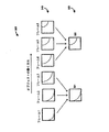
図1を参照するに、従前のアプローチの一態様を説明する。より具体的には、事例ベース超解像のエンコーダ側の処理を、参照数字100で示す。入力ビデオは、ステップ110において、(パッチ抽出及びクラスタ器151による)パッチ抽出及びクラスタリングにかけられ、クラスタリングされたパッチを求める。さらに、入力ビデオは、ステップ115において、(ダウンサイザ153により)ダウンサイジングされ、ダウンサイズされたフレームが出力される。クラスタリングされたパッチは、ステップ120において(パッチパッカー152により)パッチフレームにパッキングされ、パッキングされたパッチフレームが出力される。
Referring to FIG. 1, one aspect of the previous approach is described. More specifically, the process on the encoder side of case-based super-resolution is indicated by
図2を参照するに、従前のアプローチの他の一態様を説明する。より具体的には、事例ベース超解像のデコーダ側の処理を、参照数字200で示す。復号されたパッチフレームは、ステップ210において(パッチ抽出・処理器251により)パッチ抽出と処理がなされ、処理されたパッチを求める。処理されたパッチは、ステップ215において(パッチライブラリ252により)記憶される。復号されダウンサイジングされたフレームは、ステップ220において(アップサイザー253により)、アップサイズされる。アップサイジングされたフレームは、ステップ225において(パッチ検索・置換器254により)パッチ検索及び置換をされ、置換パッチを求める。置換パッチは、ステップ230において(後処理器255により)後処理され、高解像度フレームが得られる。
Referring to FIG. 2, another aspect of the previous approach will be described. More specifically, the processing on the decoder side of case-based super-resolution is indicated by
従前のアプローチの方法は、静的ビデオ(背景又は前景のオブジェクトに大きな動きがないビデオ)ではうまく行く。例えば、実験によると、ある種の静的ビデオの場合、圧縮効率は、事例ベース超解像を用いると、スタンドアロンのビデオエンコーダを用いる場合と比べて高くなる。スタンドアロンのビデオエンコーダとは、例えば、International Organization for Standardization / International Electro Technical Commission (ISO/IEC) Moving Picture Experts Group-4 (MPEG-4) Part 10 Advanced Video Coding (AVC) Standard / International Telecommunication Union, Telecommunication Sector (ITU-T) H.264 Recommendation(以下、MPEG-4 AVC Standardと呼ぶ)。 The previous approach method works well for static video (video where the background or foreground objects do not move significantly). For example, experiments have shown that for some types of static video, compression efficiency is higher with case-based super-resolution than with a stand-alone video encoder. Stand-alone video encoder is, for example, International Organization for Standardization / International Electro Technical Commission (ISO / IEC) Moving Picture Experts Group-4 (MPEG-4) Part 10 Advanced Video Coding (AVC) Standard / International Telecommunication Union, Telecommunication Sector (ITU-T) H.264 Recommendation (hereinafter referred to as MPEG-4 AVC Standard).
しかし、オブジェクト又は背景の動きが大きいビデオの場合、事例ベース超解像を用いた圧縮効率は、スタンドアロンMPEG-4 AVCエンコーダを用いた圧縮効率より悪くなることが多い。これは、動きが大きいビデオの場合、代表的なパッチを抽出するクラスタリングプロセスにおいては、パッチシフティングやその他の変換(例えば、ズーミング、回転など)非常に多くの冗長的な代表的パッチが生成され、パッチフレーム数が多くなり、パッチフレームの圧縮効率が低下するからである。 However, for videos with large object or background motion, compression efficiency using case-based super-resolution is often worse than compression efficiency using a stand-alone MPEG-4 AVC encoder. This is because, in the case of high-motion video, the clustering process that extracts representative patches generates a large number of redundant representative patches, including patch shifting and other transformations (eg, zooming, rotation, etc.) This is because the number of patch frames increases and the compression efficiency of the patch frames decreases.
図3を参照するに、事例ベース超解像(example-based super-resolution)に対する従前のアプローチで用いられるクラスタリングプロセスを参照数字300で示した。図3の例では、クラスタリングプロセスは6つのフレーム(フレーム1乃至フレーム6)を含む。図3では、(動いている)オブジェクトが曲線で示されている。クラスタリングプロセス300は、図3の上部と下部でしめした。上部では、入力ビデオシーケンスの連続フレームからの入力パッチ310が示されている。下部には、クラスタに対応する代表的パッチ320が示されている。具体的に、下部には、クラスタ1の代表的パッチ321と、クラスタ2の代表的パッチ322とが示されている。
Referring to FIG. 3, indicated by
要するに、データプルーニング(data pruning)用の事例ベース超解像では、デコーダ(図1参照)に、高解像度事例パッチと低解像度フレームとを送信する。デコーダは、低解像度パッチを事例の高解像度パッチで置き換えて、高解像度フレームを回復する(図2参照)。しかし、上記の通り、動きが大きいビデオの場合、代表的なパッチを抽出するクラスタリングプロセスにおいては、パッチシフティング(図3参照)やその他の変換(例えば、ズーミング、回転など)非常に多くの冗長的な代表的パッチが生成され、パッチフレーム数が多くなり、パッチフレームの圧縮効率が低下する。 In short, in case-based super-resolution for data pruning, a high-resolution case patch and a low-resolution frame are transmitted to the decoder (see FIG. 1). The decoder replaces the low resolution patch with the example high resolution patch to recover the high resolution frame (see FIG. 2). However, as described above, in the case of a video with a large amount of motion, the clustering process for extracting representative patches involves a large amount of redundancy in patch shifting (see FIG. 3) and other transformations (eg, zooming, rotation, etc.) A typical representative patch is generated, the number of patch frames increases, and the compression efficiency of the patch frames decreases.
本願は、圧縮効率が改善されたビデオ圧縮のための動き補償事例ベース超解像の方法及び装置を開示する。 The present application discloses a motion compensated case-based super-resolution method and apparatus for video compression with improved compression efficiency.
本原理の一態様によると、事例ベース超解像(example-based super-resolution)装置が提供される。本装置は、動きを有する入力ビデオシーケンスの動きパラメータを推定する動きパラメータ推定器を含む。入力ビデオシーケンスは複数の画像を含む。本装置は、複数の画像のうちの一又は複数を変換する画像ワーピングプロセスを行って、動きパラメータに基づき動き量を低減することにより、入力ビデオシーケンスの静的バージョンを提供する画像ワーパーも含む。本装置は、さらに、事例ベース超解像を行って、ビデオシーケンスの静的バージョンから一又は複数の高解像度置き換えパッチ画像を生成する事例ベース超解像プロセッサを含む。一又は複数の高解像度置き換えパッチ画像は、入力ビデオシーケンスの再構成の時に、一又は複数の低解像度パッチ画像を置き換えるものである。 According to one aspect of the present principles, case-based super-resolution (example-based super-resolution) device is provided. The apparatus includes a motion parameter estimator that estimates motion parameters of an input video sequence having motion. The input video sequence includes a plurality of images. The apparatus also includes an image warper that provides a static version of the input video sequence by performing an image warping process that transforms one or more of the plurality of images to reduce the amount of motion based on the motion parameters. The apparatus further comprises performing case-based super-resolution, a case-based super-resolution processor for generating a high resolution replacement patch images one or more of the static version of the video sequence. The one or more high-resolution replacement patch images replace one or more low-resolution patch images during reconstruction of the input video sequence.
本原理の他の一態様によると、事例ベース超解像(example-based super-resolution)方法が提供される。本方法は、動きを有する入力ビデオシーケンスの動きパラメータを推定するステップを含む。入力ビデオシーケンスは複数の画像を含む。本方法は、複数の画像のうちの一又は複数を変換する画像ワーピングプロセスを行って、動きパラメータに基づき動き量を低減することにより、入力ビデオシーケンスの静的バージョンを提供するステップも含む。本方法は、さらに、事例ベース超解像を行って、ビデオシーケンスの静的バージョンから一又は複数の高解像度置き換えパッチ画像を生成するステップを含む。一又は複数の高解像度置き換えパッチ画像は、入力ビデオシーケンスの再構成の時に、一又は複数の低解像度パッチ画像を置き換えるものである。 According to another aspect of the present principles, case-based super-resolution (example-based super-resolution) there is provided a method. The method includes estimating a motion parameter of an input video sequence having motion. The input video sequence includes a plurality of images. The method also includes providing a static version of the input video sequence by performing an image warping process that transforms one or more of the plurality of images to reduce the amount of motion based on the motion parameters. The method further includes performing case-based super-resolution to generate one or more high-resolution replacement patch images from a static version of the video sequence. The one or more high-resolution replacement patch images replace one or more low-resolution patch images during reconstruction of the input video sequence.
本原理の他の一態様によると、事例ベース超解像(example-based super-resolution)装置が提供される。本装置は、動きのある入力ビデオシーケンスの静的バージョンから生成された高解像度置き換えパッチ画像のうちの一又は複数を受け取り、事例ベース超解像を行って、前記一又は複数の高解像度置き換えパッチ画像から前記入力ビデオシーケンスの静的バージョンの再構成バージョンを生成する事例ベース超解像プロセッサを有する。入力ビデオシーケンスの静的バージョンの再構成バージョンは複数の画像を含む。装置は、さらに、前記入力ビデオシーケンスの動きパラメータを受け取り、前記動きパラメータに基づいて逆画像ワーピングプロセスを行って、前記複数の画像のうち一又は複数を変換して、前記動きを有する入力ビデオシーケンスの再構成を生成する逆画像ワーパーとを有する。 According to another aspect of the present principles, case-based super-resolution (example-based super-resolution) device is provided. The apparatus receives one or more of the high resolution replacement patch images generated from the static version of the moving input video sequence, performs case-based super-resolution, and performs the one or more high resolution replacement patches. A case-based super-resolution processor that generates a reconstructed version of the static version of the input video sequence from an image. The reconstructed version of the static version of the input video sequence includes multiple images. The apparatus further receives a motion parameter of the input video sequence, performs an inverse image warping process based on the motion parameter, converts one or more of the plurality of images, and has an input video sequence having the motion And an inverse image warper that generates a reconstruction of
本原理のさらに他の一態様によると、事例ベース超解像(example-based super-resolution)方法が提供される。本方法は、動きを有する入力ビデオシーケンスの動きパラメータと、前記入力ビデオシーケンスの静的バージョンから生成された一又は複数の高解像度置き換えパッチ画像とを受け取るステップを含む。また、本方法は、事例ベース超解像を行って、一又は複数の高解像度置き換えパッチ画像から、入力ビデオシーケンスの静的バージョンの再構成バージョンを生成するステップを含む。入力ビデオシーケンスの静的バージョンの再構成バージョンは複数の画像を含む。本方法は、さらに、前記動きパラメータに基づき逆画像ワーピングプロセスを行って、前記複数の画像のうちの一又は複数を変換して、前記動きを有する入力ビデオシーケンスの再構成を生成するステップを有する。 According to yet another aspect of the present principles, case-based super-resolution (example-based super-resolution) there is provided a method. The method includes receiving motion parameters of an input video sequence having motion and one or more high resolution replacement patch images generated from a static version of the input video sequence. The method also includes performing case-based super-resolution to generate a reconstructed version of the static version of the input video sequence from one or more high-resolution replacement patch images. The reconstructed version of the static version of the input video sequence includes multiple images. The method further comprises performing an inverse image warping process based on the motion parameter to transform one or more of the plurality of images to generate a reconstruction of the input video sequence having the motion. .
本原理のさらに他の一態様によると、事例ベース超解像(example-based super-resolution)装置が提供される。本装置は、動きを有する入力ビデオシーケンスの動きパラメータを推定する手段を含む。入力ビデオシーケンスは複数の画像を含む。本装置は、複数の画像のうちの一又は複数を変換する画像ワーピングプロセスを行って、動きパラメータに基づき動き量を低減することにより、入力ビデオシーケンスの静的バージョンを提供する手段も含む。本装置は、さらに、事例ベース超解像を行って、ビデオシーケンスの静的バージョンから一又は複数の高解像度置き換えパッチ画像を生成する手段を含む。一又は複数の高解像度置き換えパッチ画像は、入力ビデオシーケンスの再構成の時に、一又は複数の低解像度パッチ画像を置き換えるものである。 According to yet another aspect of the present principles, case-based super-resolution (example-based super-resolution) device is provided. The apparatus includes means for estimating motion parameters of an input video sequence having motion. The input video sequence includes a plurality of images. The apparatus also includes means for providing a static version of the input video sequence by performing an image warping process that transforms one or more of the plurality of images to reduce the amount of motion based on the motion parameters. The apparatus further includes means for performing case-based super-resolution to generate one or more high-resolution replacement patch images from a static version of the video sequence. The one or more high-resolution replacement patch images replace one or more low-resolution patch images during reconstruction of the input video sequence.
本原理の別の一態様によると、事例ベース超解像(example-based super-resolution)装置が提供される。本装置は、動きを有する入力ビデオシーケンスの動きパラメータと、前記入力ビデオシーケンスの静的バージョンから生成された一又は複数の高解像度置き換えパッチ画像とを受け取る手段を含む。また、本装置は、事例ベース超解像を行って、一又は複数の高解像度置き換えパッチ画像から、入力ビデオシーケンスの静的バージョンの再構成バージョンを生成する手段を含む。入力ビデオシーケンスの静的バージョンの再構成バージョンは複数の画像を含む。本装置は、さらに、前記動きパラメータに基づき逆画像ワーピングプロセスを行って、前記複数の画像のうちの一又は複数を変換して、前記動きを有する入力ビデオシーケンスの再構成を生成する手段を有する。 According to a further aspect of the present principles, case-based super-resolution (example-based super-resolution) device is provided. The apparatus includes means for receiving motion parameters of an input video sequence having motion and one or more high resolution replacement patch images generated from a static version of the input video sequence. The apparatus also includes means for performing case-based super-resolution to generate a reconstructed version of the static version of the input video sequence from one or more high-resolution replacement patch images. The reconstructed version of the static version of the input video sequence includes multiple images. The apparatus further comprises means for performing an inverse image warping process based on the motion parameters to transform one or more of the plurality of images to generate a reconstruction of an input video sequence having the motion. .
本原理の上記その他の態様、特徴、及び有利性は、添付した図面を参照して読むと、実施形態の詳細な説明から明らかとなるであろう。 These and other aspects, features, and advantages of the present principles will become apparent from the detailed description of the embodiments when read with reference to the accompanying drawings.
本原理は以下の図面を参照してよりよく理解することができる。
本原理は、ビデオ圧縮のための動き補償事例ベース超解像の方法と装置とに関する。 The present principles relate to a motion compensated case-based super-resolution method and apparatus for video compression.
この説明は本原理を例示するものである。言うまでもなく、当業者は、ここには明示的に説明や図示はしていないが、本原理を化体し、その精神と範囲内に含まれる様々な構成を工夫することができる。 This description is illustrative of the present principles. Needless to say, those skilled in the art can express the present principle and devise various configurations included in the spirit and scope of the present invention although they are not explicitly described or illustrated herein.
ここに記載したすべての例と条件付きの言葉は、発明者が技術発展に対してなした本原理とコンセプトとを、読者が理解しやすいようにするためのものであり、その解釈は具体的に記載した実施例や条件に限定されるべきではない。 All the examples and conditional words given here are intended to make it easier for the reader to understand the principles and concepts that the inventor made for technological development, and their interpretation is specific. It should not be limited to the examples and conditions described in.
さらに、本原理の原理、態様、実施形態、及びその実施例のすべての記載は、その構成的等価物及び機能的等価物の両方を含むものである。また、かかる等価物は、現在知られている等価物及び将来開発される等価物を含み、すなわち、構成にかかわらず同じ機能を発揮する開発されるすべての要素を含む。 Further, all statements of principles, aspects, embodiments, and examples of the present principles are intended to include both structural and functional equivalents thereof. Such equivalents also include currently known equivalents and equivalents that will be developed in the future, i.e., all elements that are developed that perform the same function regardless of configuration.
よって、例えば、当業者には言うまでもなく、ここに説明したブロック図は本原理を化体する回路を概念的に示すものである。同様に、言うまでもなく、フローチャート、フロー図、状態遷移図、擬似コード等は、様々な方法(processes)を表し、これらの方法をコンピュータ読み取り可能媒体に実質的に表しても、(明示的に示していようがいまいが)コンピュータやプロセッサで実行してもよい。 Thus, for example, it goes without saying to those skilled in the art that the block diagram described here conceptually shows a circuit that embodies the present principle. Similarly, it goes without saying that flowcharts, flow diagrams, state transition diagrams, pseudocode, etc. represent various processes, even if these methods are substantially represented on a computer-readable medium (shown explicitly). It may be executed by a computer or a processor.
図示した様々な要素の機能は、専用ハードウェアを用いても、ソフトウェアを実行可能なハードウェアと適当なソフトウェアとを組み合わせても提供できる。プロセッサを設けるとき、機能を単一の専用プロセッサで提供してもよいし、共有された単一のプロセッサで提供してもよいし、一部が共有された複数の個別プロセッサで提供してもよい。さらに、「プロセッサ」または「コントローラ」という用語を明示的に使用した場合、ソフトウェアを実行できるハードウェアのみをいうと解釈してはならず、限定はされないが、デジタルシグナルプロセッサ(DSP)、ソフトウェアを記憶するROM、RAM、不揮発性記憶装置を黙示的に含んでもよい。 The functions of the various elements shown in the figure can be provided using dedicated hardware or a combination of hardware capable of executing software and appropriate software. When the processor is provided, the function may be provided by a single dedicated processor, may be provided by a single shared processor, or may be provided by a plurality of individual processors that are partially shared. Good. Further, the explicit use of the terms “processor” or “controller” should not be construed to refer only to hardware capable of executing software, including but not limited to digital signal processor (DSP), software A ROM, a RAM, and a non-volatile storage device may be included implicitly.
その他のハードウェアを従来のものでもカスタムのものであっても含んでもよい。同様に、図面に示したスイッチは概念的なものである。スイッチの機能は、プログラムロジックの動作、専用ロジックの動作、プログラム制御や専用ロジックのインターラクション、またはマニュアルで実行されてもよく、具体的な方法は実施者が文脈から判断して選択できる。 Other hardware may be conventional or custom. Similarly, the switches shown in the drawings are conceptual. The function of the switch may be executed by program logic operation, dedicated logic operation, program control or dedicated logic interaction, or manually, and a specific method can be selected by a practitioner based on context.
請求項において、特定の機能を実行する手段として表した要素は、その機能を実行するいかなる方法も含み、例えば、a)その機能を実行する回路要素の組合せと、b)ファームウェアやマイクロコード等を含む任意の形式のソフトウェア及びそれと組み合わせたその機能を実行する適当な回路とを含む。請求項に記載した本原理は、記載した様々な手段が提供する機能を、請求項に記載したように組み合わせることにある。よって、これらの機能を提供できる手段はどれでも、ここに示したものと等化であると見なせる。 In the claims, elements represented as means for performing a particular function include any method for performing that function, for example: a) a combination of circuit elements that perform that function; and b) firmware, microcode, etc. Including any type of software including and appropriate circuitry to perform its function in combination therewith. The present principles set forth in the claims lie in the combination of the functions provided by the various means as described in the claims. Thus, any means that can provide these functions can be considered equivalent to that shown here.
明細書において、本発明の「一実施形態」、またはそのバリエーションと言う場合、本発明の少なくとも1つの実施形態に含まれるその実施形態に関して説明する具体的な特徴、構造、特性などを意味する。それゆえ、本明細書を通していろいろなところに記載した「一実施形態において」またはそのバリエーションは、必ずしもすべてが同じ実施形態を参照するものではない。 In the specification, reference to “one embodiment” of the present invention or a variation thereof refers to specific features, structures, characteristics, and the like described with reference to the embodiment included in at least one embodiment of the present invention. Thus, "in one embodiment" or variations thereof described variously throughout this specification are not necessarily all referring to the same embodiment.
言うまでもなく、例えば、「A/B」、「A及び/又はB」、および「AとBの少なくとも一方」のうちの「及び/又は」および「少なくとも一方」などと言うとき、第1のオプション(A)のみを選択する場合、第2のオプション(B)のみを選択する場合、又は両方のオプション(AとB)を選択する場合を含むものとする。別の例として、例えば、「A、B、及び/又はC」、および「A、B、及びCの少なくとも一方」などと言うとき、第1のオプション(A)のみを選択する場合、第2のオプション(B)のみを選択する場合、第3のオプション(C)のみを選択する場合、第1と第2のオプション(AとB)のみを選択する場合、第2と第3のオプション(BとC)を選択する場合、第1と第3のオプション(AとC)を選択する場合、又は3つすべてのオプション(AとBとC)を選択する場合を含むものとする。本技術分野及び関連技術分野の当業者には明らかなように、これは多数の場合にも拡張できる。 Needless to say, for example, when “A / B”, “A and / or B”, and “and / or” and / or “at least one” of “at least one of A and B”, the first option is used. The case where only (A) is selected, the case where only the second option (B) is selected, or the case where both options (A and B) are selected is included. As another example, for example, when saying “A, B, and / or C” and “at least one of A, B, and C”, etc., when only the first option (A) is selected, the second If only option (B) is selected, if only the third option (C) is selected, if only the first and second options (A and B) are selected, the second and third options ( The case of selecting B and C) includes the case of selecting the first and third options (A and C), or the case of selecting all three options (A, B and C). As will be apparent to those skilled in the art and related arts, this can be extended to numerous cases.
また、ここで、「ピクチャ(picture)」と「画像(image)」との用語は、交換可能に使い、静止画像とビデオシーケンスの画像とを言う。知られているように、ピクチャはフレーム又はフィールドであってもよい。 Here, the terms “picture” and “image” are used interchangeably and refer to a still image and an image of a video sequence. As is known, a picture may be a frame or a field.
上記の通り、本原理は、ビデオ圧縮のための動き補償事例ベース超解像の方法と装置とに関する。有利にも、本原理は、冗長な代表パッチの数を減らし、圧縮効率を上げる方法を提供する。 As described above, the present principles relate to a motion compensated case-based super-resolution method and apparatus for video compression. Advantageously, the present principles provide a way to reduce the number of redundant representative patches and increase compression efficiency.
本原理により、本願は、背景及びオブジェクトの動きが大きいビデオセグメントを、比較的静的なビデオセグメントに変換するコンセプトを開示する。より具体的に、図4において、オブジェクトの動きがあるビデオの静的ビデオへの変換の一例を、参照数字400で示した。変換400は、オブジェクトの動き410を有するビデオのフレーム1、フレーム2、及びフレーム3に適用して、静的ビデオ420のフレーム1、フレーム2、及びフレーム3を求めるフレームワーピング変換を含む。変換400は、クラスタリングプロセス(すなわち、事例ベース超解像の方法のエンコーダ側の処理コンポーネント)と符号化プロセスの前に行われる。変換パラメータは、回復のためデコーダ側に送信される。事例ベース超解像方法により、静的ビデオの圧縮効率は高くなり、変換パラメータデータのサイズは通常は非常に小さいので、動きのあるビデオを静的ビデオに変換することにより、動きのあるビデオでも圧縮効率を潜在的に上げることができる。
In accordance with this principle, the present application discloses the concept of converting a video segment with large background and object motion into a relatively static video segment. More specifically, in FIG. 4, an example of conversion of a video having an object motion to a static video is indicated by a
図5を参照して、エンコーダで用いるフレームワーピングを有する動き補償事例ベース超解像の装置例を、参照数字500で示した。装置500は、画像ワーパー520の入力と信号通信し得る第1の出力を有する動きパラメータ推定器510を含む。画像ワーパー520の出力は、事例ベース超解像エンコーダ側プロセッサ530の入力と信号通信可能に接続されている。事例ベース超解像エンコーダ側プロセッサ530の第1の出力は、エンコーダ540の入力と信号通信可能に接続され、それにダウンサイズされたフレームを供給する。事例ベース超解像エンコーダ側プロセッサ530の第2の出力は、エンコーダ540の入力と信号通信可能に接続され、それにパッチフレームを供給する。動きパラメータ推定器510の第2の出力は、装置500の出力となり、動きパラメータを供給する。動きパラメータ推定器510の入力は、装置500の入力となり、入力ビデオを受け取る。エンコーダ540の出力(図示せず)は、装置500の第2の出力となり、ビットストリームを出力する。ビットストリームには、例えば、符号化されたダウンサイズされたフレーム、エンコーダパッチフレーム、及び動きパラメータを含む。
With reference to FIG. 5, an example of motion compensated case based super-resolution with frame warping used in the encoder is indicated by
言うまでもなく、エンコーダ540により行われる機能すなわち符号化を行わずに、ダウンサイズされたフレーム、パッチフレーム、及び動きパラメータを、圧縮せずにデコーダ側に送信してもよい。しかし、ビットレートを節約するため、ダウンサイズされたフレームとパッチフレームは、デコーダ側に送信される前に、(エンコーダ540により)圧縮されることが好ましい。さらに、他の一実施形態では、動きパラメータ推定器510、画像ワーパー520、及び事例ベース超解像エンコーダ側プロセッサ530は、ビデオエンコーダに、又はその一部に含まれていても良い。
Needless to say, the downsized frame, the patch frame, and the motion parameter may be transmitted to the decoder side without being compressed without performing the function performed by the
よって、エンコーダ側では、クラスタリングプロセスを行う前に、(動きパラメータ推定器510により)動き推定を行い、(画像ワーパー520により)フレームワーピングプロセスを用いて、オブジェクト又は背景の動きを有するフレームを比較的静的なビデオに変換する。動き推定プロセスで抽出されたパラメータは、別のチャンネルを通じてデコーダ側に送信される。 Thus, on the encoder side, before performing the clustering process, motion estimation is performed (by the motion parameter estimator 510) and a frame warping process (by the image warper 520) is used to relatively extract frames with object or background motion. Convert to static video. The parameters extracted in the motion estimation process are transmitted to the decoder side through another channel.
図6を参照して、本原理を適用できるビデオエンコーダを参照数字600で示した。ビデオエンコーダ600は、コンバイナ685の非反転入力と信号通信している出力を有するフレーム順序付けバッファ610を含む。コンバイナ685の出力は変換器及び量子化器625の第1の入力と接続され信号通信している。変換器及び量子化器625の出力は、エントロピーコーダ645の第1の入力及び逆変換器及び逆量子化器650の第1の入力と接続され信号通信している。エントロピーコーダ645の出力は、コンバイナ690の第1の非反転入力と接続され信号通信している。コンバイナ690の出力は出力バッファ635の第1の入力と接続され信号通信している。
Referring to FIG. 6, a
エンコーダコントローラ605の第1の出力は、フレーム順序付けバッファ610の第2の入力と、逆変換器及び逆量子化器650の第2の入力と、ピクチャタイプ決定モジュール615の入力と、マクロブロックタイプ(MBタイプ)決定モジュール620の第1の入力と、イントラ予測モジュール660の第2の入力と、デブロッキングフィルタ665の第2の入力と、動き補償器670の第1の入力と、動き推定器675の第1の入力と、基準ピクチャバッファ680の第2の入力と接続され、信号通信している。
The first output of the encoder controller 605 includes the second input of the
エンコーダコントローラ605の第2の出力は、サプリメンタルエンハンスメント情報(SEI)挿入器630の第1の入力と、変換器及び量子化器625の第2の入力と、エントロピーコーダ645の第2の入力と、出力バッファ635の第2の入力と、シーケンスパラメータセット(SPS)及びピクチャパラメータセット(PPS)挿入器640の入力とに接続され、信号通信している。 The second output of encoder controller 605 includes a first input of supplemental enhancement information (SEI) inserter 630, a second input of transformer and quantizer 625, and a second input of entropy coder 645. , Connected to the second input of the output buffer 635 and the input of the sequence parameter set (SPS) and picture parameter set (PPS) inserter 640 for signal communication.
SEI挿入器630の出力は、コンバイナ690の第2の非反転入力と接続され信号通信している。 The output of the SEI inserter 630 is connected to and in signal communication with the second non-inverting input of the combiner 690.
ピクチャタイプ決定モジュール615の第1の出力は、フレーム順序付けバッファ610の第3の入力に接続され信号通信している。ピクチャタイプ決定モジュール615の第2の出力は、マクロブロックタイプ決定モジュール620の第2の入力に接続され信号通信している。
A first output of the picture type determination module 615 is connected to and in signal communication with a third input of the
シーケンスパラメータセット(SPS)及びピクチャパラメータセット(PPS)挿入器640の出力は、コンバイナ690の第3の非反転入力と接続され信号通信している。 The output of the sequence parameter set (SPS) and picture parameter set (PPS) inserter 640 is connected and in signal communication with the third non-inverting input of the combiner 690.
逆量子化及び逆変換器650の出力は、コンバイナ619の第1の非反転入力と接続され信号通信している。コンバイナ619の出力は、イントラ予測モジュール660の第1の入力と、及びデブロッキングフィルタ665の第1の入力と接続され、信号通信している。デブロッキングフィルタ665の出力は基準ピクチャバッファ680の第1の入力と接続され、信号通信している。基準ピクチャバッファ680の出力は、動き推定器675の第2の入力と、及び動き補償器670の第3の入力と接続され、信号通信している。動き推定器675の第1の出力は動き補償器670の第2の入力と接続され、信号通信している。動き推定器675の第2の出力はエントロピーコーダ645の第3の入力と接続され、信号通信している。
The output of the inverse quantization and inverse transformer 650 is connected to the first non-inverting input of the combiner 619 for signal communication. The output of the combiner 619 is connected in signal communication with the first input of the intra prediction module 660 and with the first input of the deblocking filter 665. The output of the deblocking filter 665 is connected to the first input of the reference picture buffer 680 and is in signal communication. The output of reference picture buffer 680 is connected in signal communication with a second input of
動き補償器670の出力はスイッチ697の第1の入力と接続され、信号通信している。イントラ予測モジュール660の出力はスイッチ697の第2の入力と接続され、信号通信している。マクロブロックタイプ決定モジュール620の出力はスイッチ697の第3の入力と接続され、信号通信している。スイッチ697の第3の入力は、スイッチの「データ」入力が、(制御入力すなわち第3の入力と比較して)動き補償器670から提供されるか、又はイントラ予測モジュール660から提供されるか、判断する。スイッチ697の出力は、コンバイナ619の第2の非反転入力と、及びコンバイナ685の反転入力と接続され、信号通信している。
The output of motion compensator 670 is connected to the first input of switch 697 and is in signal communication. The output of the intra prediction module 660 is connected to the second input of the switch 697 and is in signal communication. The output of the macroblock type determination module 620 is connected to the third input of the switch 697 and is in signal communication. The third input of switch 697 is whether the “data” input of the switch is provided from motion compensator 670 (compared to the control or third input) or from intra prediction module 660. ,to decide. The output of the switch 697 is connected to the second non-inverting input of the combiner 619 and the inverting input of the
フレーム順序付けバッファ610の第1の入力と、エンコーダコントローラ605の入力は、入力ピクチャを受け取る、エンコーダ600の入力としても利用可能である。さらに、サプリメンタルエンハンスメント情報(SEI)挿入器630の第2の入力は、メタデータを受け取る、エンコーダ600の入力としても利用可能である。出力バッファ635の出力は、ビットストリームを出力する、エンコーダ100の出力として利用できる。
The first input of the
言うまでもなく、図5のエンコーダ540は、エンコーダ600として実施してもよい。
Needless to say, the
図7を参照して、エンコーダで用いる動き補償事例ベース超解像の方法例を、参照数字700で示した。方法700は、開始ブロック705を含み、開始ブロック710は機能ブロック1010に制御を渡す。機能ブロック710は、オブジェクトの動きを有するビデオを入力して、機能ブロック715に制御を渡す。機能ブロック715は、オブジェクトの動きを有する入力ビデオの動きパラメータを推定して保存し、ループ制限ブロック720に制御を渡す。ループ制限ブロック720は、各フレームについてループを行い、機能ブロック725に制御を渡す。機能ブロック725において、推定された動きパラメータを用いて、現在のフレームをワープし、決定ブロック730に制御を渡す。決定ブロック730は、すべてのフレームの処理が終わったか判断する。すべてのフレームの処理が終われば、機能ブロック735に制御を渡す。機能ブロック735において、事例ベース超解像エンコーダ側処理を行い、機能ブロック750に制御を渡す。機能ブロック740は、ダウンサイズされたフレームと、パッチフレームと、動きパラメータとを出力し、終了ブロック799に制御を渡す。
With reference to FIG. 7, an example of motion compensation case-based super-resolution method used in the encoder is indicated by
図8を参照して、デコーダにおける逆フレームワーピングを有する動き補償事例ベース超解像の装置例を、参照数字800で示した。装置800は、デコーダ810を含み、上記のエンコーダ540を含む装置500により生成された信号を処理する。装置800は、事例ベース超解像デコーダ側プロセッサ820の第1の入力及び第2の入力と信号通信可能な出力を有するデコーダ810を含み、事例ベース超解像デコーダ側プロセッサ820に、(復号され)ダウンサイズされたフレームとパッチフレームをそれぞれ供給する。事例ベース超解像デコーダ側プロセッサ820の出力は、逆フレームワーパー830の入力と信号通信可能に接続され、それに超解像ビデオを供給する。逆フレームワーパー830の出力は、ビデオを出力する装置800の出力となる。逆フレームワーパー830の入力は、動きパラメータの受け取りに使える。
Referring to FIG. 8, an example of motion compensated case-based super-resolution with inverse frame warping at the decoder is indicated by
言うまでもなく、デコーダ810により行われる機能すなわち復号を行わずに、ダウンサイズされたフレーム及びパッチフレームを、圧縮せずにデコーダ側で受信してもよい。しかし、ビットレートを節約するため、ダウンサイズされたフレームとパッチフレームは、デコーダ側に送信される前に、エンコーダ側で圧縮されることが好ましい。さらに、他の一実施形態では、事例ベース超解像デコーダ側プロセッサ820と逆フレームワーパーは、ビデオデコーダ又はその一部に含まれても良い。
Needless to say, the downsized frame and the patch frame may be received on the decoder side without being compressed without performing the function performed by the
よって、デコーダ側では、フレームが事例ベース超解像により回復された後、逆ワーピングプロセスを行って、回復されたビデオセグメントを元のビデオの座標系に変換する。逆ワーピングプロセスは、エンコーダ側で推定され送信された動きパラメータを用いる。 Thus, on the decoder side, after the frame is recovered by case-based super-resolution , an inverse warping process is performed to convert the recovered video segment to the original video coordinate system. The inverse warping process uses motion parameters estimated and transmitted on the encoder side.
図9を参照して、本原理を適用できるビデオデコーダの一例を参照数字900で示した。ビデオデコーダ900は入力バッファ910を含む。入力バッファ610の出力は、エントロピーデコーダ945の第1の入力と接続され、信号通信している。エントロピーデコーダ945の第1の出力は逆変換及び逆量子化器950の第1の入力と接続され、信号通信している。逆量子化及び逆変換器950の出力は、コンバイナ925の第2の非反転入力と接続され、信号通信している。コンバイナ925の出力は、デブロッキングフィルタ965の第2の入力と、及びイントラ予測モジュール960の第1の入力と接続され、信号通信している。デブロッキングフィルタ965の第2の出力は基準ピクチャバッファ980の第1の入力と接続され、信号通信している。基準ピクチャバッファ980の出力は動き補償器970の第2の入力と接続され、信号通信している。
With reference to FIG. 9,
エントロピーデコーダ945の第2の出力は、動き報償器970の第3の入力と、デブロッキングフィルタ965の第1の入力と、及びイントラ予測器960の第3の入力と接続され、信号通信している。エントロピーデコーダ945の第3の出力はデコーダコントローラ905の入力と接続され、信号通信している。デコーダコントローラ905の第1の出力はエントロピーデコーダ945の第2の入力と接続され、信号通信している。デコーダコントローラ905の第2の出力は逆変換及び逆量子化器950の第2の入力と接続され、信号通信している。デコーダコントローラ905の第3の出力はデブロッキングフィルタ965の第3の入力と接続され、信号通信している。デコーダコントローラ905の第4の出力はイントラ予測モジュール960の第2の入力と、動き補償器970の第1の入力と、基準ピクチャバッファ980の第2の入力と接続され、信号通信している。
The second output of the entropy decoder 945 is connected to and in signal communication with the third input of the
動き補償器970の出力はスイッチ997の第1の入力と接続され、信号通信している。イントラ予測モジュール960の出力はスイッチ997の第2の入力と接続され、信号通信している。スイッチ997の出力は、コンバイナ925の第1の非反転入力と接続され、信号通信している。
The output of
入力バッファ910の入力は、入力ビットストリームを受け取る、デコーダ900の入力として利用できる。デブロッキングフィルタ965の第1の出力は、出力ピクチャを出力する、デコーダ900の出力として利用できる。
The input of the input buffer 910 can be used as an input of a
言うまでもなく、図8のデコーダは、デコーダ900として実施してもよい。
Needless to say, the decoder of FIG. 8 may be implemented as the
図10を参照して、デコーダで用いる動き補償事例ベース超解像の方法例を、参照数字1000で示した。方法1000は、開始ブロック1005を含み、開始ブロック1005は機能ブロック1010に制御を渡す。機能ブロック1010は、ダウンサイズされたフレームと、パッチフレームと、動きパラメータとを出力し、機能ブロック1015に制御を渡す。機能ブロック1015において、事例ベース超解像デコーダ側処理を行い、ループ制限ブロック1020に制御を渡す。ループ制限ブロック1020は、各フレームについてループを行い、機能ブロック1025に制御を渡す。機能ブロック1025において、受信した動きパラメータを用いて逆フレームワーピングし、決定ブロック1030に制御を渡す。決定ブロック1030は、すべてのフレームの処理が終わったか判断する。すべてのフレームの処理が終われば、機能ブロック1035に制御を渡す。終わっていなければ、機能ブロック1020に制御を戻す。機能ブロック1035において、回復したビデオを出力し、終了ブロック1099に制御を渡す。
With reference to FIG. 10, an example method of motion compensation example-based super-resolution used in the decoder is indicated by
入力ビデオはグループオブフレーム(GOF)に分割される。各GOFは、動き推定、フレームワーピング、及び事例ベース超解像のための基本単位である。GOFの複数のフレームのうちの一フレーム(例えば、中間又は始めのフレーム)が、動き推定の基準フレームとして選択される。GOFの長さは固定でも可変でもよい。 The input video is divided into groups of frames (GOF). Each GOF is a basic unit for motion estimation, frame warping, and case-based super-resolution . One frame (for example, an intermediate or first frame) of a plurality of frames of the GOF is selected as a reference frame for motion estimation. The length of the GOF may be fixed or variable.
動き推定
動き推定を用いて、フレーム中の画素の基準フレームに対する変位を推定する。動きパラメータをデコーダ側に送信しなければならないので、動きパラメータの数はできるだけ少ない方がよい。それゆえ、少数のパラメータにより制御できる、あるパラメトリック動きモデルを選択することが好ましい。例えば、ここに開示する現在のシステムでは、8個のパラメータで特徴付けられる平面動きモデルを利用する。かかるパラメトリック動きモデルは、並進、回転、アフィンワープ(affine warp)、投影変換などのフレーム間のグローバルな動きをモデル化できる。これらの動きは異なる多くのタイプのビデオに共通のものである。例えば、カメラがパンするとき、カメラパニング(camera panning)は並進運動となる。このモデルでは、前景のオブジェクトの動きはよくキャプチャできないこともあるが、前景のオブジェクトが小さく、背景の動きが大きい場合、変換後のビデオはほとんど静的なものとなる。もちろん、8個のパラメータにより特徴付けられるパラメトリック動きモデルは、単なる例示であり、本原理の教示により、本原理の精神を維持しつつ、8個より多い又は少ないパラメータで、又は8個のパラメータで特徴付けられる他のパラメトリック動きモデルを用いてもよい。
Motion estimation The motion estimation is used to estimate the displacement of the pixels in the frame relative to the reference frame. Since motion parameters must be transmitted to the decoder side, the number of motion parameters should be as small as possible. It is therefore preferable to select a parametric motion model that can be controlled by a small number of parameters. For example, the current system disclosed herein utilizes a planar motion model characterized by eight parameters. Such parametric motion models can model global motion between frames such as translation, rotation, affine warp, projection transformation and the like. These movements are common to many different types of video. For example, when the camera pans, camera panning is a translational motion. In this model, the motion of the foreground object may not be captured well, but if the foreground object is small and the background motion is large, the converted video will be almost static. Of course, a parametric motion model characterized by eight parameters is merely exemplary, and with the teaching of the present principles, with more or fewer parameters, or with eight parameters, while maintaining the spirit of the principles. Other parametric motion models that may be characterized may be used.
一般性を失わずに、基準フレームをH1、GOF中の残りのフレームをHi(i=2,3,...,N)とする。2つのフレームHiとフレームHjとの間のグローバルな動きは、Hi中の画素をHj中の対応する画素の位置に、又はその逆に動かす変換により、特徴付けられる。HiからHjへの変換をΘijと記し、そのパラメータをθijと記す。変換Θijを用いてHiをHjに(又は逆モデルΘji=Θij −1を用いてその逆に)アライメント(すなわちワープ)することができる。 Without loss of generality, let the reference frame be H 1 and the remaining frames in the GOF be H i (i = 2, 3,..., N). Global motion between two frames H i and frame H j is the pixel in the H i to the position of the corresponding pixel in the H j, or by the conversion of moving vice versa, characterized. The transformation from H i to H j is denoted as Θ ij and its parameter is denoted as θ ij . The transformation Θ ij can be used to align (ie warp) H i to H j (or vice versa using the inverse model Θ ji = Θ ij −1 ).
グローバルな動きは、いろいろなモデルと方法を用いて推定でき、そのため、本原理は、グローバルな動きを推定する特定の方法及び/又はモデルに限定されない。一例として、よく使われる一モデル(ここで参照する現在のシステムで用いられるモデル)は、

で与えられる投影変換である。
Global motion can be estimated using a variety of models and methods, so the present principles are not limited to a particular method and / or model for estimating global motion. As an example, one commonly used model (the model used in the current system referenced here) is
Is the projection transformation given by.
上記の式により、Hi中の位置(x,y)にある画素が移った、Hj中の新しい位置(x,y)が与えられる。このように、8個のモデルパラメータθij={a1,a2,a3,b1,b2,b3,c1,c2}がHiからHjへの動きを記述する。通常、パラメータは、最初に2つのフレーム間の一組の点対応を決定し、次にRANdom SAmple Consensus (RANSAC)又はそのバリエーションを用いて、ロバスト推定フレームワークを用いることにより、推定される。このバリエーションは、例えば次の文献に記載されているものである:M. A. Fischler and R. C. Bolles, "Random Sample Consensus: A Paradigm for Model Fitting with Applications to Image Analysis and Automated Cartography," Communications of the ACM, vol. 24, 1981, pp. 381-395、及びP. H. S. Torr and A. Zisserman, "MLESAC: A New Robust Estimator with Application to Estimating Image Geometry," Journal of Computer Vision and Image Understanding, vol. 78, no. 1, 2000, pp. 138-156。フレーム間の点対応は、多数の方法で決定できる。例えば、文献D. G. Lowe, "Distinctive image features from scale- invariant keypoints," International Journal of Computer Vision, vol. 2, no. 60, 2004, pp. 91-110に記載されているような、SIFT(Scale-Invariant Feature Transform)特性を抽出してマッチングすることにより、又は、文献M. J. Black and P. Anandan, "The robust estimation of multiple motions: Parametric and piecewise-smooth flow fields," Computer Vision and Image Understanding, vol. 63, no. 1, 1996, pp. 75-104に記載されているようなオプティカルフロー(optical flow)を用いることにより、決定できる。 The above equation gives a new position (x, y) in H j to which the pixel at position (x, y) in H i has moved. Thus, the eight model parameters θ ij = {a 1 , a 2 , a 3 , b 1 , b 2 , b 3 , c 1 , c 2 } describe the movement from H i to H j . Typically, the parameters are estimated by first determining a set of point correspondences between two frames and then using a robust estimation framework using RANdom SAmple Consensus (RANSAC) or variations thereof. This variation is described, for example, in the following document: MA Fischler and RC Bolles, "Random Sample Consensus: A Paradigm for Model Fitting with Applications to Image Analysis and Automated Cartography," Communications of the ACM, vol. 24, 1981, pp. 381-395, and PHS Torr and A. Zisserman, "MLESAC: A New Robust Estimator with Application to Estimating Image Geometry," Journal of Computer Vision and Image Understanding, vol. 78, no. 1, 2000 , pp. 138-156. Point correspondence between frames can be determined in a number of ways. For example, as described in the document DG Lowe, “Distinctive image features from scale-invariant keypoints,” International Journal of Computer Vision, vol. 2, no. 60, 2004, pp. 91-110, SIFT (Scale- Invariant Feature Transform) by extracting and matching characteristics, or by the literature MJ Black and P. Anandan, "The robust estimation of multiple motions: Parametric and piecewise-smooth flow fields," Computer Vision and Image Understanding, vol. 63 No. 1, 1996, pp. 75-104, and can be determined by using an optical flow.
グローバルな動きパラメータを用いて、GOF中の(基準フレームを除く)フレームをワープ(warp)して、基準フレームとアライメント(align)する。それゆえ、各フレームHi(i=2,3,...,N)と基準フレーム(H1)との間の動きパラメータを推定しなければならない。変換は可逆であり、逆変換Θji=Θij −1はHjからHiへの動きを記述する。変換結果のフレームを元のフレームにワープするために逆変換を用いる。元のビデオセグメントを回復するため、デコーダ側で逆変換を用いる。変換パラメータは圧縮され、サイドチャンネルを通じてデコーダ側に送信され、ビデオ復元プロセスを促進する。 Using global motion parameters, warp frames in the GOF (excluding the reference frame) and align them with the reference frame. Therefore, the motion parameters between each frame H i (i = 2, 3,..., N) and the reference frame (H 1 ) must be estimated. The transformation is reversible and the inverse transformation Θ ji = Θ ij −1 describes the movement from H j to H i . Inverse transformation is used to warp the resulting frame to the original frame. In order to recover the original video segment, an inverse transform is used on the decoder side. The transformation parameters are compressed and sent to the decoder side through the side channel to facilitate the video restoration process.
本原理により、グローバル動きモデルの他に、ブロックベース法などの動き推定方法を用いて、より高い精度を達成できる。ブロックベースの方法により、フレームを複数のブロックに分割して、各ブロックの動きモデルを推定する。しかし、ブロックベースモデルを用いて動きを記述するには、非常に多いビットが必要である。 According to this principle, higher accuracy can be achieved by using a motion estimation method such as a block-based method in addition to the global motion model. A frame is divided into a plurality of blocks by a block-based method, and a motion model of each block is estimated. However, describing a motion using a block-based model requires a very large number of bits.
フレームワーピング及び逆フレームワーピング
動きパラメータを推定した後、エンコーダ側において、フレームワーピングプロセスを行い、非基準フレームを基準フレームにアライメント(align)する。しかし、ビデオフレーム中のあるエリアが、上記のグローバル動きモデルに従わない可能性もる。フレームワーピングを用いることにより、これらのエリアは、そのフレーム中の残りのエリアとともに変換される。しかし、このエリアが小さければ、これは大きな問題とはならない。このエリアのワーピングにより、ワープされたフレーム中のこのエリアにだけに人工的な動きが生じるからである。人工的な動きを有するこのエリアが小さい限り、そのための代表パッチが大幅に増加することにはならない。全体的に、ワーピングプロセスにより、代表パッチの総数を低減することができる。また、小さいエリアの人工的な動きは、逆ワーピングプロセスにより可逆される。
Frame Warping and Inverse Frame Warping After estimating the motion parameters, the encoder side performs a frame warping process to align the non-reference frame with the reference frame. However, some areas in the video frame may not follow the global motion model described above. By using frame warping, these areas are transformed along with the remaining areas in the frame. But if this area is small, this is not a big problem. This is because the warping of this area causes an artificial movement only in this area in the warped frame. As long as this area with artificial movement is small, the representative patches for it will not increase significantly. Overall, the total number of representative patches can be reduced by the warping process. Also, the artificial movement of small areas is reversible by the reverse warping process.
逆フレームワーピングプロセスは、デコーダ側で行われ、事例ベース超解像コンポーネントからの復元されたフレームをワープして元の座標系に戻す。 The inverse frame warping process is performed at the decoder side and warps the reconstructed frame from the case-based super-resolution component back to the original coordinate system.
本原理の上記その他の特徴と利点は、当業者はここに開示した教示に基づき容易に確認できるであろう。言うまでもなく、本原理の教示は、ハードウェア、ソフトウェア、ファームウェア、特殊用途プロセッサ、またはこれらの組み合わせなどのいろいろな形体で実施することができる。 These and other features and advantages of the present principles will be readily ascertainable by one skilled in the art based on the teachings disclosed herein. Of course, the teachings of the present principles may be implemented in various forms such as hardware, software, firmware, special purpose processors, or combinations thereof.
最も好ましくは、本原理の教示をハードウェアとソフトウェアの組合せとして実施する。また、ソフトウェアはプログラム記録装置に実態的に化体されたアプリケーションプログラムとして実施してもよい。そのアプリケーションプログラムは、好適なアーキテクチャを有する機械にアップロードされ、実行される。好ましくは、機械は、中央処理装置(CPU)、ランダムアクセスメモリ(RAM)、及び入出力(I/O)インターフェイス等のハードウェアを有するコンピュータプラットフォームで実施される。コンピュータプラットフォームはオペレーティングシステムとマイクロコードも含んでもよい。ここに説明した様々なプロセスや機能は、CPUが実行できる、マイクロ命令コードの一部やアプリケーションプログラムの一部であってもよく、これらのいかなる組合せであってもよい。また、追加的データ記憶装置や印刷装置等その他の様々な周辺装置をコンピュータプラットフォームに接続してもよい。 Most preferably, the teachings of the present principles are implemented as a combination of hardware and software. The software may be implemented as an application program that is actually embodied in the program recording apparatus. The application program is uploaded and executed on a machine having a suitable architecture. Preferably, the machine is implemented on a computer platform having hardware such as a central processing unit (CPU), a random access memory (RAM), and an input / output (I / O) interface. The computer platform may also include an operating system and microcode. The various processes and functions described herein may be a part of microinstruction code or a part of an application program that can be executed by the CPU, or any combination thereof. In addition, various other peripheral devices such as an additional data storage device and a printing device may be connected to the computer platform.
さらに言うまでもなく、添付した図面に示したシステム構成要素や方法の一部はソフトウェアで実施されることが好ましいが、システム構成要素(または方法)間の実際的な結合は本原理をプログラムするそのプログラム方法に応じて異なる。ここに開示された本発明の教示を受けて、関連技術分野の当業者は、本原理の同様な実施形態や構成を考えることができるであろう。 Needless to say, some of the system components and methods shown in the accompanying drawings are preferably implemented in software, but the actual coupling between system components (or methods) is a program that programs the present principles. It depends on the method. Given the teachings of the invention disclosed herein, one of ordinary skill in the related art will be able to contemplate similar embodiments and configurations of the present principles.
例示した実施形態を添付した図面を参照して説明したが、言うまでもなく、本原理はこれらの実施形態には限定されず、当業者は、本原理の範囲と精神から逸脱することなく、様々な変化と修正を施すことができるであろう。かかる変更や修正はすべて添付した請求項に記載した本原理の範囲内に含まれるものである。
なお、実施形態について次の付記を記す。
(付記1) 動きを有する入力ビデオシーケンスであって複数のピクチャを含むものの動きパラメータを推定する動きパラメータ推定器と、
前記複数のピクチャのうちの一又は複数を変換するピクチャワーピングプロセスを行って、前記動きパラメータに基づき動き量を低減することにより、前記入力ビデオシーケンスの静的バージョンを提供する画像ワーパーと、
事例ベース超解像を行い、前記ビデオシーケンスの静的バージョンから一又は複数の高解像度置き換えパッチピクチャであって前記入力ビデオシーケンスの再構成において一又は複数の低解像度パッチピクチャを置き換えるものを生成する事例ベース超解像プロセッサとを有する、装置。
(付記2) 前記事例ベース超解像プロセッサは、前記入力ビデオシーケンスから、一又は複数のダウンサイズされたピクチャを生成し、前記一又は複数のダウンサイズされたピクチャは、前記複数のピクチャの一又は複数にそれぞれ対応し、前記入力ビデオシーケンスの再構成で用いられる、付記1に記載の装置。
(付記3) 前記装置はビデオエンコーダモジュールに含まれている、付記1に記載の装置。
(付記4) 前記動きパラメータは、基準ピクチャと前記複数のピクチャのうちの他の少なくとも一のピクチャとの間のグローバルな動きをモデル化する平面動きモデルを用いて推定され、前記グローバルな動きは、前記基準ピクチャ中の画素を前記他の少なくとも一のピクチャ中の画素に動かす一又は複数の可逆な変換を含み、又は前記他の少なくとも一のピクチャ中の画素を前記基準ピクチャに動かす一又は複数の可逆な変換を含む、
付記1に記載の装置。
(付記5) 前記動きパラメータはグループオブピクチャごとに推定される、
付記1に記載の装置。
(付記6) 前記動きパラメータは、前記複数のピクチャを複数のブロックにパーティションし、前記複数のブロックのそれぞれの動きモデルを推定するブロックベース動きアプローチを用いて推定される、付記1に記載の装置。
(付記7) 前記ピクチャワーピングプロセスは、前記複数のピクチャよりなるグループオブピクチャ中の基準ピクチャを、前記グループオブピクチャ中の非基準ピクチャとアライメントする、付記1に記載の装置。
(付記8) 動きを有する入力ビデオシーケンスであって複数のピクチャを含むものの動きパラメータを推定するステップと、
前記複数のピクチャのうちの一又は複数を変換するピクチャワーピングプロセスを行って、前記動きパラメータに基づき動き量を低減することにより、前記入力ビデオシーケンスの静的バージョンを提供するステップと、
事例ベース超解像を行い、前記ビデオシーケンスの静的バージョンから一又は複数の高解像度置き換えパッチピクチャであって前記入力ビデオシーケンスの再構成において一又は複数の低解像度パッチピクチャを置き換えるものを生成するステップとを有する、
方法。
(付記9) 前記事例ベース超解像を行うステップは、前記入力ビデオシーケンスから一又は複数のダウンサイズされたピクチャを生成するステップを有し、前記一又は複数のダウンサイズされたピクチャは、前記複数のピクチャの一又は複数にそれぞれ対応し、前記入力ビデオシーケンスの再構成で用いられる、付記8に記載の方法。
(付記10) 前記方法はビデオエンコーダで行われる、付記8に記載の方法。
(付記11) 前記動きパラメータは、基準ピクチャと前記複数のピクチャのうちの他の少なくとも一のピクチャとの間のグローバルな動きをモデル化する平面動きモデルを用いて推定され、前記グローバルな動きは、前記基準ピクチャ中の画素を前記他の少なくとも一のピクチャ中の同一位置の画素に動かす一又は複数の可逆な変換を含み、又は前記他の少なくとも一のピクチャ中の画素を前記基準ピクチャ中の同一位置の他の画素に動かす一又は複数の可逆な変換を含む、付記8に記載の方法。
(付記12) 前記動きパラメータはグループオブピクチャごとに推定される、
付記8に記載の方法。
(付記13) 前記動きパラメータは、前記複数のピクチャを複数のブロックにパーティションし、前記複数のブロックのそれぞれの動きモデルを推定するブロックベース動きアプローチを用いて推定される、付記8に記載の方法。
(付記14) 前記ピクチャワーピングプロセスは、前記複数のピクチャよりなるグループオブピクチャ中の基準ピクチャを、前記グループオブピクチャ中の非基準ピクチャとアライメントする、付記8に記載の方法。
(付記15) 動きを有する入力ビデオシーケンスであって複数のピクチャを有するものの動きパラメータを推定する手段と、
前記複数のピクチャのうちの一又は複数を変換するピクチャワーピングプロセスを行って、前記動きパラメータに基づき動き量を低減することにより、前記入力ビデオシーケンスの静的バージョンを提供する手段と、
事例ベース超解像を行い、前記ビデオシーケンスの静的バージョンから一又は複数の高解像度置き換えパッチピクチャであって前記入力ビデオシーケンスの再構成において一又は複数の低解像度パッチピクチャを置き換えるものを生成する手段とを有する、
装置。
(付記16) 前記事例ベース超解像を行う手段は、前記入力ビデオシーケンスから、一又は複数のダウンサイズされたピクチャを生成し、前記一又は複数のダウンサイズされたピクチャは、前記複数のピクチャの一又は複数にそれぞれ対応し、前記入力ビデオシーケンスの再構成で用いられる、付記15に記載の装置。
(付記17) 前記動きパラメータは、基準ピクチャと前記複数のピクチャのうちの他の少なくとも一のピクチャとの間のグローバルな動きをモデル化する平面動きモデルを用いて推定され、前記グローバルな動きは、前記基準ピクチャ中の画素を前記他の少なくとも一のピクチャ中の同一位置の画素に動かす一又は複数の可逆な変換を含み、又は前記他の少なくとも一のピクチャ中の画素を前記基準ピクチャ中の同一位置の他の画素に動かす一又は複数の可逆な変換を含む、付記15に記載の装置。
(付記18) 前記動きパラメータはグループオブピクチャごとに推定される、
付記15に記載の装置。
(付記19) 前記動きパラメータは、前記複数のピクチャを複数のブロックにパーティションし、前記複数のブロックのそれぞれの動きモデルを推定するブロックベース動きアプローチを用いて推定される、付記15に記載の装置。
(付記20) 前記ピクチャワーピングプロセスは、前記複数のピクチャよりなるグループオブピクチャ中の基準ピクチャを、前記グループオブピクチャ中の非基準ピクチャとアライメントする、付記15に記載の装置。
While the illustrated embodiments have been described with reference to the accompanying drawings, it will be understood that the present principles are not limited to these embodiments, and those skilled in the art will be able to understand various aspects without departing from the scope and spirit of the principles. Changes and modifications could be made. All such changes and modifications are intended to be included within the scope of the present principles as set forth in the appended claims.
In addition, the following additional notes are described about the embodiment.
(Supplementary note 1) A motion parameter estimator for estimating a motion parameter of an input video sequence having motion and including a plurality of pictures;
An image warper that provides a static version of the input video sequence by performing a picture warping process that transforms one or more of the plurality of pictures to reduce the amount of motion based on the motion parameters;
Perform case-based super-resolution to generate one or more high-resolution replacement patch pictures from the static version of the video sequence that replace one or more low-resolution patch pictures in the reconstruction of the input video sequence An apparatus having a case-based super-resolution processor.
(Supplementary Note 2) The case-based super-resolution processor generates one or more downsized pictures from the input video sequence, and the one or more downsized pictures are one of the plurality of pictures. Or the apparatus according to appendix 1, which corresponds to each of a plurality and is used in the reconstruction of the input video sequence.
(Supplementary note 3) The device according to supplementary note 1, wherein the device is included in a video encoder module.
(Supplementary Note 4) The motion parameter is estimated using a planar motion model that models a global motion between a reference picture and at least one other picture of the plurality of pictures, and the global motion is One or more reversible transformations that move pixels in the reference picture to pixels in the at least one other picture, or one or more that move pixels in the at least one other picture to the reference picture Including reversible transformations of
The apparatus according to appendix 1.
(Supplementary Note 5) The motion parameter is estimated for each group of pictures.
The apparatus according to appendix 1.
(Supplementary note 6) The apparatus according to supplementary note 1, wherein the motion parameter is estimated using a block-based motion approach that partitions the plurality of pictures into a plurality of blocks and estimates a motion model of each of the plurality of blocks. .
(Supplementary note 7) The apparatus according to supplementary note 1, wherein the picture warping process aligns a reference picture in a group of pictures composed of the plurality of pictures with a non-reference picture in the group of pictures.
(Supplementary Note 8) Estimating a motion parameter of an input video sequence having motion, including a plurality of pictures;
Providing a static version of the input video sequence by performing a picture warping process that transforms one or more of the plurality of pictures to reduce the amount of motion based on the motion parameters;
Perform case-based super-resolution to generate one or more high-resolution replacement patch pictures from the static version of the video sequence that replace one or more low-resolution patch pictures in the reconstruction of the input video sequence And having steps
Method.
(Supplementary Note 9) The step of performing the case-based super-resolution includes generating one or more downsized pictures from the input video sequence, and the one or more downsized pictures include The method according to claim 8, wherein the method corresponds to one or more of a plurality of pictures and is used in the reconstruction of the input video sequence.
(Supplementary note 10) The method according to supplementary note 8, wherein the method is performed by a video encoder.
(Supplementary Note 11) The motion parameter is estimated using a planar motion model that models a global motion between a reference picture and at least one other picture of the plurality of pictures, and the global motion is One or more reversible transformations that move a pixel in the reference picture to a co-located pixel in the at least one other picture, or a pixel in the at least one other picture in the reference picture 9. The method of claim 8 including one or more reversible transformations that move to other pixels at the same location.
(Supplementary Note 12) The motion parameter is estimated for each group of pictures.
The method according to appendix 8.
(Supplementary note 13) The method according to supplementary note 8, wherein the motion parameter is estimated using a block-based motion approach that partitions the plurality of pictures into a plurality of blocks and estimates a motion model of each of the plurality of blocks. .
(Supplementary note 14) The method according to supplementary note 8, wherein the picture warping process aligns a reference picture in a group of pictures composed of the plurality of pictures with a non-reference picture in the group of pictures.
(Supplementary Note 15) Means for estimating a motion parameter of an input video sequence having motion and having a plurality of pictures;
Means for providing a static version of the input video sequence by performing a picture warping process that transforms one or more of the plurality of pictures to reduce the amount of motion based on the motion parameters;
Perform case-based super-resolution to generate one or more high-resolution replacement patch pictures from the static version of the video sequence that replace one or more low-resolution patch pictures in the reconstruction of the input video sequence Having means,
apparatus.
(Supplementary Note 16) The case-based super-resolution unit generates one or more downsized pictures from the input video sequence, and the one or more downsized pictures are the plurality of pictures. 16. The apparatus according to appendix 15, wherein the apparatus corresponds to one or more of each and is used in the reconstruction of the input video sequence.
(Supplementary Note 17) The motion parameter is estimated using a planar motion model that models global motion between a reference picture and at least one other picture of the plurality of pictures, and the global motion is One or more reversible transformations that move a pixel in the reference picture to a co-located pixel in the at least one other picture, or a pixel in the at least one other picture in the reference picture The apparatus of claim 15 comprising one or more reversible transformations that move to other pixels at the same location.
(Supplementary Note 18) The motion parameter is estimated for each group of pictures.
The apparatus according to appendix 15.
(Supplementary note 19) The apparatus according to supplementary note 15, wherein the motion parameter is estimated using a block-based motion approach that partitions the plurality of pictures into a plurality of blocks and estimates a motion model of each of the plurality of blocks. .
(Supplementary note 20) The apparatus according to supplementary note 15, wherein the picture warping process aligns a reference picture in a group of pictures composed of the plurality of pictures with a non-reference picture in the group of pictures.
Claims (11)
前記複数のピクチャのうちの一以上のピクチャを変換するピクチャワーピングプロセスを行って、前記動きパラメータに基づき動き量を低減することにより、前記入力ビデオシーケンスの静的バージョンを提供するステップと、
クラスタリングプロセスを用いて、前記入力ビデオシーケンスの静的バージョンに基づき一以上の代表的パッチを生成するステップと、
前記静的バージョンをダウンサイズして、ダウンサイズした前記静的バージョンを符号化するステップと、
ダウンサイズされ符号化された前記静的バージョンを復号して、前記入力ビデオシーケンスのダウンサイズされた再構成されたバージョンを構成するステップと、
前記ビデオシーケンスのダウンサイズされた再構成された静的バージョンをアップサイズして、再構成された静的バージョンを構成するステップと、
前記再構成された静的バージョンの一以上のパッチが前記一以上の代表的パッチで置き換えられる事例ベース超解像を行うステップとを有する、
方法。 Determining a motion parameter of an input video sequence having motion and comprising a plurality of pictures;
Providing a static version of the input video sequence by performing a picture warping process that transforms one or more pictures of the plurality of pictures to reduce the amount of motion based on the motion parameters;
Generating one or more representative patches based on a static version of the input video sequence using a clustering process;
Downsize the static version and encode the downsized static version;
Decoding the downsized and encoded static version to form a downsized reconstructed version of the input video sequence;
Upsizing a downsized reconstructed static version of the video sequence to form a reconstructed static version;
And a steps in which one or more patches of static version of the reconstructed performs case-based RET be replaced by typical patch of the one or more,
Method.
請求項1に記載の方法。 The motion parameter is determined for each group of pictures.
The method of claim 1.
前記複数のピクチャのうちの一以上を変換するピクチャワーピングプロセスを行って、前記動きパラメータに基づき動き量を低減することにより、前記入力ビデオシーケンスの静的バージョンを提供する手段と、
クラスタリングプロセスを用いて、前記入力ビデオシーケンスの静的バージョンに基づき一以上の代表的パッチを生成する手段と、
前記静的バージョンをダウンサイズして、ダウンサイズした前記静的バージョンを符号化する手段と、
ダウンサイズされ符号化された前記静的バージョンを復号して、前記入力ビデオシーケンスのダウンサイズされた再構成されたバージョンを構成する手段と、
前記ビデオシーケンスのダウンサイズされた再構成された静的バージョンをアップサイズして、再構成された静的バージョンを構成する手段と、
前記再構成された静的バージョンの一以上のパッチが前記一以上の代表的パッチで置き換えられる事例ベース超解像を行う手段とを有する、
装置。 Means for determining motion parameters of an input video sequence having motion and having a plurality of pictures;
Means for providing a static version of the input video sequence by performing a picture warping process to transform one or more of the plurality of pictures to reduce the amount of motion based on the motion parameters;
Means for generating one or more representative patches based on a static version of the input video sequence using a clustering process;
Means for downsizing the static version and encoding the downsized static version;
Means for decoding the downsized and encoded static version to form a downsized reconstructed version of the input video sequence;
Means for up-sizing a downsized reconstructed static version of the video sequence to form a reconstructed static version;
And a hand stage in which one or more patches of static version of the reconstructed performs case-based RET be replaced by typical patch of the one or more,
apparatus.
請求項7に記載の装置。 The motion parameter is determined for each group of pictures.
The apparatus according to claim 7 .
Applications Claiming Priority (3)
| Application Number | Priority Date | Filing Date | Title |
|---|---|---|---|
| US40308610P | 2010-09-10 | 2010-09-10 | |
| US61/403,086 | 2010-09-10 | ||
| PCT/US2011/050913 WO2012033962A2 (en) | 2010-09-10 | 2011-09-09 | Methods and apparatus for encoding video signals using motion compensated example-based super-resolution for video compression |
Publications (3)
| Publication Number | Publication Date |
|---|---|
| JP2013537380A JP2013537380A (en) | 2013-09-30 |
| JP2013537380A5 JP2013537380A5 (en) | 2014-10-30 |
| JP6042813B2 true JP6042813B2 (en) | 2016-12-14 |
Family
ID=44652031
Family Applications (2)
| Application Number | Title | Priority Date | Filing Date |
|---|---|---|---|
| JP2013528306A Pending JP2013537381A (en) | 2010-09-10 | 2011-09-09 | Method and apparatus for decoding video signal using motion compensated learning super-resolution for video compression |
| JP2013528305A Expired - Fee Related JP6042813B2 (en) | 2010-09-10 | 2011-09-09 | Method and apparatus for encoding video signals using motion compensated case-based super-resolution for video compression |
Family Applications Before (1)
| Application Number | Title | Priority Date | Filing Date |
|---|---|---|---|
| JP2013528306A Pending JP2013537381A (en) | 2010-09-10 | 2011-09-09 | Method and apparatus for decoding video signal using motion compensated learning super-resolution for video compression |
Country Status (7)
| Country | Link |
|---|---|
| US (2) | US20130163673A1 (en) |
| EP (2) | EP2614641A2 (en) |
| JP (2) | JP2013537381A (en) |
| KR (2) | KR101878515B1 (en) |
| CN (2) | CN103210645B (en) |
| BR (1) | BR112013004107A2 (en) |
| WO (2) | WO2012033962A2 (en) |
Families Citing this family (12)
| Publication number | Priority date | Publication date | Assignee | Title |
|---|---|---|---|---|
| WO2011090798A1 (en) * | 2010-01-22 | 2011-07-28 | Thomson Licensing | Data pruning for video compression using example-based super-resolution |
| JP5911809B2 (en) | 2010-01-22 | 2016-04-27 | トムソン ライセンシングThomson Licensing | Sampling-based super-resolution video encoding and decoding method and apparatus |
| US9544598B2 (en) | 2010-09-10 | 2017-01-10 | Thomson Licensing | Methods and apparatus for pruning decision optimization in example-based data pruning compression |
| US9338477B2 (en) | 2010-09-10 | 2016-05-10 | Thomson Licensing | Recovering a pruned version of a picture in a video sequence for example-based data pruning using intra-frame patch similarity |
| WO2013105946A1 (en) * | 2012-01-11 | 2013-07-18 | Thomson Licensing | Motion compensating transformation for video coding |
| CN104376544B (en) * | 2013-08-15 | 2017-04-19 | 北京大学 | Non-local super-resolution reconstruction method based on multi-region dimension zooming compensation |
| US9774865B2 (en) | 2013-12-16 | 2017-09-26 | Samsung Electronics Co., Ltd. | Method for real-time implementation of super resolution |
| JP6986721B2 (en) * | 2014-03-18 | 2021-12-22 | パナソニックIpマネジメント株式会社 | Decoding device and coding device |
| CN106056540A (en) * | 2016-07-08 | 2016-10-26 | 北京邮电大学 | Video time-space super-resolution reconstruction method based on robust optical flow and Zernike invariant moment |
| JP6921966B2 (en) * | 2017-01-27 | 2021-08-18 | アパリオ グローバル ソリューションズ (アーゲーエス) アーゲー | Methods and systems for communicating alternative image content on physical displays to different viewers |
| CN111882486B (en) * | 2020-06-21 | 2023-03-10 | 南开大学 | A mixed-resolution multi-view video super-resolution method based on low-rank prior information |
| CN118283201B (en) * | 2024-06-03 | 2024-10-15 | 上海蜜度科技股份有限公司 | Video synthesis method, system, storage medium and electronic equipment |
Family Cites Families (22)
| Publication number | Priority date | Publication date | Assignee | Title |
|---|---|---|---|---|
| US11711A (en) | 1854-09-19 | William h | ||
| US10711A (en) | 1854-03-28 | Improvement in furnaces for zinc-white | ||
| US5537155A (en) * | 1994-04-29 | 1996-07-16 | Motorola, Inc. | Method for estimating motion in a video sequence |
| US6043838A (en) * | 1997-11-07 | 2000-03-28 | General Instrument Corporation | View offset estimation for stereoscopic video coding |
| US6766067B2 (en) * | 2001-04-20 | 2004-07-20 | Mitsubishi Electric Research Laboratories, Inc. | One-pass super-resolution images |
| US7656950B2 (en) * | 2002-05-29 | 2010-02-02 | Diego Garrido | Video interpolation coding |
| US7119837B2 (en) * | 2002-06-28 | 2006-10-10 | Microsoft Corporation | Video processing system and method for automatic enhancement of digital video |
| AU2002951574A0 (en) * | 2002-09-20 | 2002-10-03 | Unisearch Limited | Method of signalling motion information for efficient scalable video compression |
| DE10310023A1 (en) * | 2003-02-28 | 2004-09-16 | Fraunhofer-Gesellschaft zur Förderung der angewandten Forschung e.V. | Method and arrangement for video coding, the video coding comprising texture analysis and texture synthesis, as well as a corresponding computer program and a corresponding computer-readable storage medium |
| US7218796B2 (en) * | 2003-04-30 | 2007-05-15 | Microsoft Corporation | Patch-based video super-resolution |
| KR100504594B1 (en) * | 2003-06-27 | 2005-08-30 | 주식회사 성진씨앤씨 | Method of restoring and reconstructing a super-resolution image from a low-resolution compressed image |
| US7715658B2 (en) * | 2005-08-03 | 2010-05-11 | Samsung Electronics Co., Ltd. | Apparatus and method for super-resolution enhancement processing |
| US7460730B2 (en) * | 2005-08-04 | 2008-12-02 | Microsoft Corporation | Video registration and image sequence stitching |
| CN100413316C (en) * | 2006-02-14 | 2008-08-20 | 华为技术有限公司 | A video image super-resolution reconstruction method |
| US7933464B2 (en) * | 2006-10-17 | 2011-04-26 | Sri International | Scene-based non-uniformity correction and enhancement method using super-resolution |
| KR101381600B1 (en) * | 2006-12-20 | 2014-04-04 | 삼성전자주식회사 | Method and apparatus for encoding and decoding using texture synthesis |
| US8417037B2 (en) * | 2007-07-16 | 2013-04-09 | Alexander Bronstein | Methods and systems for representation and matching of video content |
| JP4876048B2 (en) * | 2007-09-21 | 2012-02-15 | 株式会社日立製作所 | Video transmission / reception method, reception device, video storage device |
| WO2009087641A2 (en) * | 2008-01-10 | 2009-07-16 | Ramot At Tel-Aviv University Ltd. | System and method for real-time super-resolution |
| WO2010122502A1 (en) * | 2009-04-20 | 2010-10-28 | Yeda Research And Development Co. Ltd. | Super-resolution from a single signal |
| CN101551903A (en) * | 2009-05-11 | 2009-10-07 | 天津大学 | Super-resolution image restoration method in gait recognition |
| WO2011090798A1 (en) * | 2010-01-22 | 2011-07-28 | Thomson Licensing | Data pruning for video compression using example-based super-resolution |
-
2011
- 2011-09-09 EP EP11757721.3A patent/EP2614641A2/en not_active Withdrawn
- 2011-09-09 KR KR1020137009099A patent/KR101878515B1/en active IP Right Grant
- 2011-09-09 KR KR1020137006098A patent/KR101906614B1/en active IP Right Grant
- 2011-09-09 US US13/820,901 patent/US20130163673A1/en not_active Abandoned
- 2011-09-09 BR BR112013004107A patent/BR112013004107A2/en not_active Application Discontinuation
- 2011-09-09 WO PCT/US2011/050913 patent/WO2012033962A2/en active Application Filing
- 2011-09-09 EP EP11757722.1A patent/EP2614642A2/en not_active Withdrawn
- 2011-09-09 JP JP2013528306A patent/JP2013537381A/en active Pending
- 2011-09-09 JP JP2013528305A patent/JP6042813B2/en not_active Expired - Fee Related
- 2011-09-09 CN CN201180043275.8A patent/CN103210645B/en not_active Expired - Fee Related
- 2011-09-09 US US13/821,078 patent/US20130163676A1/en not_active Abandoned
- 2011-09-09 WO PCT/US2011/050915 patent/WO2012033963A2/en active Application Filing
- 2011-09-09 CN CN201180043723.4A patent/CN103141092B/en not_active Expired - Fee Related
Also Published As
| Publication number | Publication date |
|---|---|
| CN103141092A (en) | 2013-06-05 |
| US20130163673A1 (en) | 2013-06-27 |
| CN103210645B (en) | 2016-09-07 |
| KR20130105827A (en) | 2013-09-26 |
| US20130163676A1 (en) | 2013-06-27 |
| WO2012033962A3 (en) | 2012-09-20 |
| WO2012033962A2 (en) | 2012-03-15 |
| WO2012033963A2 (en) | 2012-03-15 |
| KR101878515B1 (en) | 2018-07-13 |
| KR20130143566A (en) | 2013-12-31 |
| BR112013004107A2 (en) | 2016-06-14 |
| KR101906614B1 (en) | 2018-10-10 |
| EP2614642A2 (en) | 2013-07-17 |
| CN103141092B (en) | 2016-11-16 |
| JP2013537380A (en) | 2013-09-30 |
| EP2614641A2 (en) | 2013-07-17 |
| WO2012033963A8 (en) | 2012-07-19 |
| JP2013537381A (en) | 2013-09-30 |
| WO2012033963A3 (en) | 2012-09-27 |
| CN103210645A (en) | 2013-07-17 |
Similar Documents
| Publication | Publication Date | Title |
|---|---|---|
| JP6042813B2 (en) | Method and apparatus for encoding video signals using motion compensated case-based super-resolution for video compression | |
| Agustsson et al. | Scale-space flow for end-to-end optimized video compression | |
| JP2013537381A5 (en) | ||
| CN102823242B (en) | Based on sampling super-resolution Video coding and the method and apparatus of decoding | |
| CN107318026B (en) | Video encoder and video encoding method | |
| KR101838320B1 (en) | Video decoding using example - based data pruning | |
| US9554145B2 (en) | Re-encoding image sets using frequency-domain differences | |
| JP7591338B2 (en) | Decoding using signaling of segmentation information | |
| CN114793282B (en) | Neural network-based video compression with bit allocation | |
| JP5844745B2 (en) | Method and apparatus for reducing vector quantization error through patch shifting | |
| WO2023001042A1 (en) | Signaling of down-sampling information for video bitstreams | |
| WO2024015639A9 (en) | Neural network-based image and video compression method with parallel processing |
Legal Events
| Date | Code | Title | Description |
|---|---|---|---|
| A521 | Request for written amendment filed |
Free format text: JAPANESE INTERMEDIATE CODE: A523 Effective date: 20140908 |
|
| A621 | Written request for application examination |
Free format text: JAPANESE INTERMEDIATE CODE: A621 Effective date: 20140908 |
|
| A977 | Report on retrieval |
Free format text: JAPANESE INTERMEDIATE CODE: A971007 Effective date: 20150814 |
|
| A131 | Notification of reasons for refusal |
Free format text: JAPANESE INTERMEDIATE CODE: A131 Effective date: 20150901 |
|
| A601 | Written request for extension of time |
Free format text: JAPANESE INTERMEDIATE CODE: A601 Effective date: 20151201 |
|
| A521 | Request for written amendment filed |
Free format text: JAPANESE INTERMEDIATE CODE: A523 Effective date: 20151224 |
|
| A131 | Notification of reasons for refusal |
Free format text: JAPANESE INTERMEDIATE CODE: A131 Effective date: 20160322 |
|
| A601 | Written request for extension of time |
Free format text: JAPANESE INTERMEDIATE CODE: A601 Effective date: 20160621 |
|
| A521 | Request for written amendment filed |
Free format text: JAPANESE INTERMEDIATE CODE: A523 Effective date: 20160920 |
|
| TRDD | Decision of grant or rejection written | ||
| A01 | Written decision to grant a patent or to grant a registration (utility model) |
Free format text: JAPANESE INTERMEDIATE CODE: A01 Effective date: 20161018 |
|
| A61 | First payment of annual fees (during grant procedure) |
Free format text: JAPANESE INTERMEDIATE CODE: A61 Effective date: 20161110 |
|
| R150 | Certificate of patent or registration of utility model |
Ref document number: 6042813 Country of ref document: JP Free format text: JAPANESE INTERMEDIATE CODE: R150 |
|
| S111 | Request for change of ownership or part of ownership |
Free format text: JAPANESE INTERMEDIATE CODE: R313113 |
|
| S531 | Written request for registration of change of domicile |
Free format text: JAPANESE INTERMEDIATE CODE: R313531 |
|
| R371 | Transfer withdrawn |
Free format text: JAPANESE INTERMEDIATE CODE: R371 |
|
| R371 | Transfer withdrawn |
Free format text: JAPANESE INTERMEDIATE CODE: R371 |
|
| S531 | Written request for registration of change of domicile |
Free format text: JAPANESE INTERMEDIATE CODE: R313531 |
|
| R350 | Written notification of registration of transfer |
Free format text: JAPANESE INTERMEDIATE CODE: R350 |
|
| LAPS | Cancellation because of no payment of annual fees | ||
| S111 | Request for change of ownership or part of ownership |
Free format text: JAPANESE INTERMEDIATE CODE: R313113 |
|
| R350 | Written notification of registration of transfer |
Free format text: JAPANESE INTERMEDIATE CODE: R350 |