JP5844745B2 - Method and apparatus for reducing vector quantization error through patch shifting - Google Patents
Method and apparatus for reducing vector quantization error through patch shifting Download PDFInfo
- Publication number
- JP5844745B2 JP5844745B2 JP2012551975A JP2012551975A JP5844745B2 JP 5844745 B2 JP5844745 B2 JP 5844745B2 JP 2012551975 A JP2012551975 A JP 2012551975A JP 2012551975 A JP2012551975 A JP 2012551975A JP 5844745 B2 JP5844745 B2 JP 5844745B2
- Authority
- JP
- Japan
- Prior art keywords
- patch
- patches
- video sequence
- input video
- high resolution
- Prior art date
- Legal status (The legal status is an assumption and is not a legal conclusion. Google has not performed a legal analysis and makes no representation as to the accuracy of the status listed.)
- Expired - Fee Related
Links
Images


Classifications
-
- H—ELECTRICITY
- H04—ELECTRIC COMMUNICATION TECHNIQUE
- H04N—PICTORIAL COMMUNICATION, e.g. TELEVISION
- H04N19/00—Methods or arrangements for coding, decoding, compressing or decompressing digital video signals
- H04N19/10—Methods or arrangements for coding, decoding, compressing or decompressing digital video signals using adaptive coding
- H04N19/134—Methods or arrangements for coding, decoding, compressing or decompressing digital video signals using adaptive coding characterised by the element, parameter or criterion affecting or controlling the adaptive coding
- H04N19/136—Incoming video signal characteristics or properties
- H04N19/137—Motion inside a coding unit, e.g. average field, frame or block difference
- H04N19/139—Analysis of motion vectors, e.g. their magnitude, direction, variance or reliability
-
- H—ELECTRICITY
- H04—ELECTRIC COMMUNICATION TECHNIQUE
- H04N—PICTORIAL COMMUNICATION, e.g. TELEVISION
- H04N19/00—Methods or arrangements for coding, decoding, compressing or decompressing digital video signals
- H04N19/10—Methods or arrangements for coding, decoding, compressing or decompressing digital video signals using adaptive coding
- H04N19/102—Methods or arrangements for coding, decoding, compressing or decompressing digital video signals using adaptive coding characterised by the element, parameter or selection affected or controlled by the adaptive coding
- H04N19/103—Selection of coding mode or of prediction mode
- H04N19/105—Selection of the reference unit for prediction within a chosen coding or prediction mode, e.g. adaptive choice of position and number of pixels used for prediction
-
- G—PHYSICS
- G06—COMPUTING; CALCULATING OR COUNTING
- G06T—IMAGE DATA PROCESSING OR GENERATION, IN GENERAL
- G06T1/00—General purpose image data processing
-
- H—ELECTRICITY
- H04—ELECTRIC COMMUNICATION TECHNIQUE
- H04N—PICTORIAL COMMUNICATION, e.g. TELEVISION
- H04N19/00—Methods or arrangements for coding, decoding, compressing or decompressing digital video signals
- H04N19/10—Methods or arrangements for coding, decoding, compressing or decompressing digital video signals using adaptive coding
- H04N19/134—Methods or arrangements for coding, decoding, compressing or decompressing digital video signals using adaptive coding characterised by the element, parameter or criterion affecting or controlling the adaptive coding
- H04N19/136—Incoming video signal characteristics or properties
- H04N19/14—Coding unit complexity, e.g. amount of activity or edge presence estimation
-
- H—ELECTRICITY
- H04—ELECTRIC COMMUNICATION TECHNIQUE
- H04N—PICTORIAL COMMUNICATION, e.g. TELEVISION
- H04N19/00—Methods or arrangements for coding, decoding, compressing or decompressing digital video signals
- H04N19/50—Methods or arrangements for coding, decoding, compressing or decompressing digital video signals using predictive coding
- H04N19/59—Methods or arrangements for coding, decoding, compressing or decompressing digital video signals using predictive coding involving spatial sub-sampling or interpolation, e.g. alteration of picture size or resolution
-
- H—ELECTRICITY
- H04—ELECTRIC COMMUNICATION TECHNIQUE
- H04N—PICTORIAL COMMUNICATION, e.g. TELEVISION
- H04N19/00—Methods or arrangements for coding, decoding, compressing or decompressing digital video signals
- H04N19/50—Methods or arrangements for coding, decoding, compressing or decompressing digital video signals using predictive coding
- H04N19/593—Methods or arrangements for coding, decoding, compressing or decompressing digital video signals using predictive coding involving spatial prediction techniques
-
- H—ELECTRICITY
- H04—ELECTRIC COMMUNICATION TECHNIQUE
- H04N—PICTORIAL COMMUNICATION, e.g. TELEVISION
- H04N19/00—Methods or arrangements for coding, decoding, compressing or decompressing digital video signals
- H04N19/90—Methods or arrangements for coding, decoding, compressing or decompressing digital video signals using coding techniques not provided for in groups H04N19/10-H04N19/85, e.g. fractals
- H04N19/94—Vector quantisation
Landscapes
- Engineering & Computer Science (AREA)
- Multimedia (AREA)
- Signal Processing (AREA)
- Physics & Mathematics (AREA)
- General Physics & Mathematics (AREA)
- Theoretical Computer Science (AREA)
- Compression Or Coding Systems Of Tv Signals (AREA)
- Compression, Expansion, Code Conversion, And Decoders (AREA)
- Television Systems (AREA)
- Image Processing (AREA)
Description
関連出願の相互参照
本願は、参照によりその全体が本明細書に組み込まれる2010年2月2日出願の米国特許仮出願第61/300551号明細書の利益を主張する。
This application claims the benefit of US Provisional Application No. 61/300551, filed Feb. 2, 2010, which is incorporated herein by reference in its entirety.
本原理は、一般にはベクトル量子化に関し、より詳細には、パッチシフティングを通じてベクトル量子化誤差を低減する方法および装置に関する。 The present principles relate generally to vector quantization, and more particularly to a method and apparatus for reducing vector quantization errors through patch shifting.
本発明者等は以前に、ビデオデータプルーニングのための事例に基づく超解像度化方法および装置(example−based super resolution method and apparatus for video data pruning)(以後、「事例に基づく超解像度化方法」と呼ぶ)を開発した。事例に基づく超解像度化は、入力ピクチャ内の低解像度パッチを照会キーワードとして使用してパッチライブラリ内の高解像度パッチを見つけ、低解像度入力ピクチャ内の低解像度パッチを、取り出した高解像度パッチで置き換えることによって低解像度ピクチャを高解像度ピクチャに変換する超解像度技法である。 The inventors previously described an example-based super resolution method and apparatus for video data pruning (hereinafter “example-based super-resolution method”). Developed). Case-based super-resolution finds high-resolution patches in the patch library using low-resolution patches in the input picture as query keywords, and replaces low-resolution patches in the low-resolution input picture with the retrieved high-resolution patches This is a super-resolution technique for converting a low-resolution picture into a high-resolution picture.
さらに詳細には、この事例に基づく超解像度化方法では、エンコーダ側の高解像度ビデオフレームをイメージパッチまたはブロックに分割する(例えば、事例に基づく超解像度化方法の一実装では、16×16ピクセルブロックを使用する)。次いで、イメージパッチをいくつかのクラスタにグループ化する。クラスタの代表的パッチを小型化フレームと共にデコーダ側に送る。デコーダ側では、代表的パッチを抽出する。低解像度ビデオ内のパッチを高解像度の代表的パッチで置き換え、回復後高解像度ビデオを生成する。 More particularly, the case-based super-resolution method divides a high-resolution video frame on the encoder side into image patches or blocks (eg, in one implementation of the case-based super-resolution method, a 16 × 16 pixel block Use). The image patches are then grouped into several clusters. A representative patch of the cluster is sent to the decoder side along with the miniaturized frame. On the decoder side, representative patches are extracted. Replace patches in the low resolution video with high resolution representative patches to generate a high resolution video after recovery.
図1を参照すると、事例に基づく超解像度化システム/方法のハイレベルブロック図が、全般的に参照符号100で示されている。ステップ110で、高解像度(HR)フレームが入力され、小型化フレームおよびパッチフレームを得るために(エンコーダ側プリプロセッサ151によって)エンコーダ側前処理を施す。ステップ115で、(エンコーダ152によって)小型化フレームおよびパッチフレームを符号化する。ステップ120で、(デコーダ153によって)符号化小型化フレームおよびパッチフレームを復号化する。ステップ125で、高解像度出力フレームを供給するために(超解像度ポストプロセッサ154によって)低小型化フレームおよびパッチフレームに超解像度後処理を施す。
Referring to FIG. 1, a high level block diagram of a case-based super-resolution system / method is indicated generally by the
図2を参照すると、図1の事例に基づく超解像度化システム/方法に対応するエンコーダ側前処理のハイレベルブロック図が、全般的に参照符号200で示されている。ステップ210で、(パッチ抽出およびクラスタ化部(clusterer)251によって)入力ビデオにパッチ抽出およびクラスタ化を施す。さらに、ステップ215で、(ダウンサイザ252によって)入力ビデオに小型化も施し、ダウンサイザ252から小型化フレームを出力する。ステップ220で、(パッチパッカ252によって)クラスタ化パッチをパッチフレームにパックし、パッチパッカ252から(パック済み)パッチフレームを出力する。
Referring to FIG. 2, a high-level block diagram of encoder-side preprocessing corresponding to a super-resolution system / method based on the example of FIG. At
図3を参照すると、図1の事例に基づく超解像度化システム/方法に対応するデコーダ側後処理のハイレベルブロック図が、全般的に参照符号300で示されている。ステップ310で、(パッチ抽出およびクラスタ化部351によって)符号化パッチフレームにパッチ抽出および処理を施し、処理済みパッチを得る。ステップ315で、(パッチライブラリ352によって)処理済みパッチを格納する。ステップ320で、(アップサイザ353によって)復号化小型化フレームに大型化を施し、大型化フレームを得る。ステップ325で、(パッチ探索および置換部354によって)大型化フレームにパッチ探索および置換を施し、置換パッチを得る。ステップ330で、(ポストプロセッサ355によって)置換パッチに後処理を施し、高解像度フレームを得る。
Referring to FIG. 3, a high level block diagram of decoder side post-processing corresponding to the super-resolution system / method based on the example of FIG. In
図1〜3に関する事例に基づく超解像度化システム/方法の主要な構成要素は、パッチクラスタ化およびパッチ置換である。このプロセスは、ベクトル量子化ベースの圧縮といくつかの共通点を有する。システムが静的シーンを有するビデオに適用されるとき、ビデオを非常に良好に回復することができる。しかし、入力ビデオが動きを有する場合、回復後ビデオにジッタリングアーチファクトが観測される可能性がある。アーチファクトは、パッチクラスタ化およびパッチ置換プロセスによって引き起こされる。図4を参照すると、動きによって引き起こされる量子化誤差が、全般的に参照符号400で示されている。量子化誤差は、6つのフレーム(フレーム1からフレーム6と呼ぶ)で取り込まれる(動いている)オブジェクトである。(動いている)オブジェクトが図4で曲線で示されている。量子化誤差400が、図4の上側部分、中央部分、および下側部分に関して示されている。上側部分では、入力ビデオシーケンスの連続するフレームからの共に位置する入力パッチ410が示されている。中央部分では、クラスタに対応する代表的パッチ420が示されている。具体的には、中央部分は、クラスタ1の代表的パッチ421、およびクラスタ2の代表的パッチ422を示す。下側部分では、回復後ビデオシーケンス中のパッチ430が示されている。ビデオシーケンス中のオブジェクトの動きにより、オブジェクトの縁部がシフトするパッチのシーケンスが得られる。連続するフレームのシーケンス中のパッチは非常に類似して見えるので、1つのクラスタ(または何らかの他の少ない数のクラスタ)にグループ化され、単一の代表的パッチ(または何らかの他の少ない数の代表的パッチ)として表される。クラスタ数は、処理すべきビデオシーケンス中の連続するフレーム数よりも明らかに少ないはずなので、先行する文では「少ない」という用語を使用する。回復プロセスの間に、対応する低解像度パッチが、クラスタに関連する代表的パッチで置き換えられる。異なる空間シフトを有するパッチが同一のパッチで置き換えられるので、回復後ビデオ中のオブジェクトの縁部がフレームにわたってジャンプし、その結果、ジッタリングアーチファクトが生じる。
The key components of the example-based super-resolution system / method with respect to FIGS. 1-3 are patch clustering and patch replacement. This process has some in common with vector quantization based compression. When the system is applied to video with static scenes, the video can be recovered very well. However, if the input video has motion, jittering artifacts may be observed in the recovered video. Artifacts are caused by the patch clustering and patch replacement process. Referring to FIG. 4, the quantization error caused by motion is indicated generally by the reference numeral 400. The quantization error is an object that is captured (moved) in six frames (referred to as frames 1 to 6). The (moving) object is shown as a curve in FIG. A quantization error 400 is shown for the upper, middle, and lower portions of FIG. In the upper part, the
本発明者等の上述の事例に基づく超解像度化方法および装置に加えて、他の事例に基づく超解像度化手法も存在することに留意されたい。したがって、他の事例に基づく超解像度化手法に関して、パッチ置換プロセスのアーチファクト問題に対処されていないことに留意されたい。1つの理由は、最初の従来技術の手法による、事例に基づく超解像度化アルゴリズムが、ビデオ用ではなくイメージ用に開発されたことである可能性がある。さらに、上述の最初の従来技術の手法によるシステムならびに類似のシステムは、圧縮のためではなく、超解像度のために開発されたので、クラスタ化構成要素を有さず、したがって、そのシステムのアーチファクト問題は、図1〜3に関して上記で説明したビデオデータプルーニングのための事例に基づく超解像度化方法ほどには深刻ではないことがある。 Note that in addition to our super-resolution method and apparatus based on the above-mentioned cases, there are other cases of super-resolution techniques. Thus, it should be noted that the patch replacement process artifact problem is not addressed with respect to other case-based super-resolution techniques. One reason may be that the first prior art approach, a case-based super-resolution algorithm, was developed for images rather than video. In addition, the system according to the first prior art approach described above as well as similar systems were developed for super-resolution, not for compression, so they do not have clustering components, and therefore the artifact problem of that system. May not be as serious as the super-resolution method based on the case for video data pruning described above with respect to FIGS.
要約すると、データプルーニングのための事例に基づく超解像度化は、高解像度(本明細書では「high−res」とも呼ぶ)イグザンプルパッチおよび低解像度(本明細書では「low−res」とも呼ぶ)フレームをデコーダに送る。デコーダは、低解像度パッチをイグザンプル高解像度パッチで置き換えることによって高解像度フレームを回復する(図3参照)。しかし、動きのあるビデオでは、しばしば、パッチ置換プロセスの結果、ベクトル量子化(VQ)誤差によるジッタリングアーチファクトが生じる。 In summary, case-based super-resolution for data pruning is a high resolution (also referred to herein as “high-res”) example patch and low resolution (also referred to herein as “low-res”). Send the frame to the decoder. The decoder recovers the high resolution frame by replacing the low resolution patch with the example high resolution patch (see FIG. 3). However, in moving video, the patch replacement process often results in jittering artifacts due to vector quantization (VQ) errors.
従来技術のこれらおよび他の欠点および不利が、パッチシフティングを通じてベクトル量子化誤差を低減する方法および装置を対象とする本原理によって対処される。 These and other shortcomings and disadvantages of the prior art are addressed by the present principles directed to methods and apparatus that reduce vector quantization errors through patch shifting.
本原理の一態様によれば、装置が提供される。この装置は、入力ビデオシーケンスから、1つまたは複数の高解像度置換パッチを生成するパッチジェネレータを含む。1つまたは複数の高解像度置換パッチは、入力ビデオシーケンスの再構築中に1つまたは複数の低解像度パッチを置き換えるためのものである。パッチジェネレータは、パッチ空間シフティングプロセスに対応するデータを使用して、1つまたは複数の高解像度置換パッチを生成する。パッチ空間シフティングプロセスは、1つまたは複数の高解像度置換パッチ内の動き誘導ベクトル量子化誤差によって引き起こされるジッタの多いアーチファクト(jittery artifact)を低減するためのものである。データは、パッチ空間シフティングプロセスでの使用に適するようにするために1つまたは複数の低解像度パッチのパッチサイズよりも大きいパッチサイズを有するような1つまたは複数の高解像度置換パッチを生成するように、1つまたは複数の高解像度置換パッチのパッチサイズを少なくとも導出するためのものである。 According to one aspect of the present principles, an apparatus is provided. The apparatus includes a patch generator that generates one or more high resolution replacement patches from an input video sequence. The one or more high resolution replacement patches are for replacing the one or more low resolution patches during reconstruction of the input video sequence. The patch generator uses the data corresponding to the patch space shifting process to generate one or more high resolution replacement patches. The patch space shifting process is intended to reduce jittery artifacts caused by motion induced vector quantization errors in one or more high resolution replacement patches. The data generates one or more high-resolution replacement patches that have a patch size that is larger than the patch size of one or more low-resolution patches to make it suitable for use in a patch space shifting process. As such, it is for deriving at least the patch size of one or more high resolution replacement patches.
本原理の別の態様によれば、プロセッサを使用して実行される方法が提供される。この方法は、入力ビデオシーケンスから、1つまたは複数の高解像度置換パッチを生成することを含む。1つまたは複数の高解像度置換パッチは、入力ビデオシーケンスの再構築中に1つまたは複数の低解像度パッチを置き換えるためのものである。生成するステップは、パッチ空間シフティングプロセスに対応するデータを使用して、1つまたは複数の高解像度置換パッチを生成する。パッチ空間シフティングプロセスは、1つまたは複数の高解像度置換パッチ内の動き誘導ベクトル量子化誤差によって引き起こされるジッタの多いアーチファクトを低減するためのものである。データは、パッチ空間シフティングプロセスでの使用に適するようにするために1つまたは複数の低解像度パッチのパッチサイズよりも大きいパッチサイズを有するような1つまたは複数の高解像度置換パッチを生成するように、1つまたは複数の高解像度置換パッチのパッチサイズを少なくとも導出するためのものである。 According to another aspect of the present principles, a method is provided that is performed using a processor. The method includes generating one or more high resolution replacement patches from an input video sequence. The one or more high resolution replacement patches are for replacing the one or more low resolution patches during reconstruction of the input video sequence. The generating step generates one or more high resolution replacement patches using data corresponding to the patch space shifting process. The patch space shifting process is for reducing jittery artifacts caused by motion induced vector quantization errors in one or more high resolution replacement patches. The data generates one or more high-resolution replacement patches that have a patch size that is larger than the patch size of one or more low-resolution patches to make it suitable for use in a patch space shifting process. As such, it is for deriving at least the patch size of one or more high resolution replacement patches.
本原理のさらに別の態様によれば、装置が提供される。この装置は、動き誘導ベクトル量子化誤差を有する1つまたは複数の高解像度置換パッチを受け取り、1つまたは複数の高解像度置換パッチを少なくとも空間的にシフトして、動き誘導ベクトル量子化誤差によって引き起こされるジッタの多いアーチファクトを低減するパッチシフタを含む。1つまたは複数の高解像度置換パッチは、入力ビデオシーケンスに対応し、入力ビデオシーケンスから導出される。装置は、入力ビデオシーケンスに対応し、入力ビデオシーケンスから導出された1つまたは複数の空間的にシフトした高解像度置換パッチおよび1つまたは複数の小型化ピクチャを使用して入力ビデオシーケンスを再構築する、パッチシフタと信号通信するピクチャ再構築デバイスをさらに含む。 According to yet another aspect of the present principles, an apparatus is provided. The apparatus receives one or more high-resolution replacement patches having motion-induced vector quantization errors, and at least spatially shifts the one or more high-resolution replacement patches caused by motion-induced vector quantization errors. Includes a patch shifter that reduces jittery artifacts. One or more high-resolution replacement patches correspond to the input video sequence and are derived from the input video sequence. The apparatus reconstructs an input video sequence using one or more spatially shifted high resolution replacement patches and one or more miniaturized pictures derived from the input video sequence corresponding to the input video sequence A picture reconstruction device in signal communication with the patch shifter.
本原理のさらに別の態様によれば、プロセッサを使用して実行される方法が提供される。この方法は、動き誘導ベクトル量子化誤差を有する1つまたは複数の高解像度置換パッチを受け取ることを含む。この方法は、1つまたは複数の高解像度置換パッチを少なくとも空間的にシフトして、動き誘導ベクトル量子化誤差によって引き起こされるジッタの多いアーチファクトを低減することをさらに含む。1つまたは複数の高解像度置換パッチは、入力ビデオシーケンスに対応し、入力ビデオシーケンスから導出される。この方法はまた、入力ビデオシーケンスに対応し、入力ビデオシーケンスから導出された1つまたは複数の空間的にシフトした高解像度置換パッチおよび1つまたは複数の小型化ピクチャを使用して入力ビデオシーケンスを再構築することをも含む。 According to yet another aspect of the present principles, a method is provided that is performed using a processor. The method includes receiving one or more high resolution replacement patches having motion induced vector quantization errors. The method further includes at least spatially shifting the one or more high resolution replacement patches to reduce jittery artifacts caused by motion induced vector quantization errors. One or more high-resolution replacement patches correspond to the input video sequence and are derived from the input video sequence. The method also corresponds to the input video sequence and uses the one or more spatially shifted high resolution replacement patches and one or more miniaturized pictures derived from the input video sequence to Including rebuilding.
添付の図面と共に読むべきである例示的実施形態の以下の詳細な説明から、本原理のこれらおよび他の態様、特徴、および利点が明らかとなるであろう。 These and other aspects, features and advantages of the present principles will become apparent from the following detailed description of exemplary embodiments, which should be read in conjunction with the accompanying drawings.
以下の例示的な図に従って本原理をより良く理解することができる。 The principles can be better understood according to the following illustrative figures.
本原理は、パッチシフティングを通じてベクトル量子化誤差を低減する方法および装置を対象とする。 The present principles are directed to a method and apparatus for reducing vector quantization errors through patch shifting.
本説明は本原理を例示する。したがって、本明細書には明示的には説明または図示していないが、本原理を具体化し、本原理の趣旨および範囲内に含まれる様々な構成を当業者は考案できることを理解されよう。 This description illustrates this principle. Thus, although not explicitly described or illustrated herein, it will be understood that those skilled in the art can devise various configurations that embody the principles and fall within the spirit and scope of the principles.
本明細書に記載のすべての例および条件的言語は、当技術分野を促進することに対して本発明者(等)が寄与する本原理および概念を読者が理解するのを助ける、教育的な目的のためのものであり、そのような具体的に記載した例および条件に限定されないと解釈されるべきである。 All examples and conditional languages described herein are educational, helping readers understand the principles and concepts that the inventors (etc.) contribute to promoting the art. It should be construed for purposes and not limited to such specifically described examples and conditions.
さらに、本原理の原理、態様、および実施形態、ならびにその特定の例を説明する本明細書のすべての陳述は、その構造的等価物と機能的等価物の両方を包含するものとする。さらに、そのような等価物は、現在知られている等価物、ならびに将来開発される等価物の両方、すなわち構造の如何に関わらず同一の機能を実行する、開発される任意の要素を含むものとする。 Moreover, all statements herein reciting principles, aspects, and embodiments of the present principles, as well as specific examples thereof, are intended to encompass both structural and functional equivalents thereof. Further, such equivalents are intended to include both currently known equivalents as well as equivalents developed in the future, i.e., any element being developed that performs the same function regardless of structure. .
したがって、例えば、本明細書で提示するブロック図が本原理を具体化する例示的回路の概念図を表すことを当業者は理解されよう。同様に、コンピュータまたはプロセッサが明示的に示されているか否かに関わらず、任意のフローチャート、流れ図、状態遷移図、疑似コードなどが、実質上コンピュータ可読媒体で表すことができ、次いでそのようなコンピュータまたはプロセッサによって実行することのできる様々なプロセスを表すことを理解されよう。 Thus, for example, those skilled in the art will appreciate that the block diagrams presented herein represent conceptual diagrams of exemplary circuits that embody the principles. Similarly, any flowchart, flowchart, state transition diagram, pseudocode, etc., regardless of whether a computer or processor is explicitly shown, can be represented in a substantially computer-readable medium, and then It will be understood that it represents various processes that can be performed by a computer or processor.
図に示す様々な要素の機能は、専用ハードウェア、ならびに適切なソフトウェアに関連してソフトウェアを実行することのできるハードウェアを使用することによって実現することができる。プロセッサで実現されるとき、単一の専用プロセッサ、単一の共有プロセッサ、または一部が共有されることのある複数の個々のプロセッサによって機能を実現することができる。さらに、「プロセッサ」または「コントローラ」という用語の明示的な使用が、ソフトウェアを実行することのできるハードウェアをもっぱら指すと解釈すべきではなく、限定はしないが、暗黙的に、デジタル信号プロセッサ(「DSP」)ハードウェア、ソフトウェアを格納する読取り専用メモリ(「ROM」)、ランダムアクセスメモリ(「RAM」)、および不揮発性ストレージを含むことができる。 The functions of the various elements shown in the figures can be realized by using dedicated hardware as well as hardware capable of executing software in conjunction with appropriate software. When implemented with a processor, the functions may be implemented by a single dedicated processor, a single shared processor, or multiple individual processors, some of which may be shared. Furthermore, the explicit use of the terms “processor” or “controller” should not be construed to refer solely to hardware capable of executing software, but is not limited to, implicitly, digital signal processors ( "DSP") hardware, read only memory ("ROM") for storing software, random access memory ("RAM"), and non-volatile storage.
従来型および/またはカスタムの他のハードウェアも含めることができる。同様に、図に示す任意のスイッチは概念的なものに過ぎない。その機能は、プログラムロジックの動作、専用ロジック、プログラム制御と専用ロジックの対話、さらには手動によって実行することができ、文脈からより具体的に理解できるように、実装者によって特定の技法が選択可能である。 Other conventional and / or custom hardware can also be included. Similarly, any switches shown in the figures are conceptual only. Its functionality can be performed manually by program logic operation, dedicated logic, program control and dedicated logic interaction, and can be selected manually by the implementer so that it can be understood more specifically from the context. It is.
本明細書の特許請求の範囲では、指定の機能を実行する手段として表される任意の要素は、例えば、a)その機能を実行する回路要素の組合せ、b)ソフトウェアを実行して機能を実行するための適切な回路と組み合わされる、任意の形態のソフトウェア、したがってファームウェア、マイクロコードなどを含むソフトウェアを含む、その機能を実行する任意の方式を包含するものとする。そのような特許請求の範囲によって定義される本原理は、様々な記載の手段によって提供される機能が、特許請求の範囲が求める方式で組み合わされ、互いに一緒にされることにある。したがって、そのような機能を提供することのできる任意の手段が、本明細書で示すものと同等であるとみなされる。 In the claims of this specification, any element represented as a means for executing a specified function may be, for example, a) a combination of circuit elements that execute the function, or b) executing a function by executing software. It is intended to encompass any manner of performing that function, including any form of software, and thus software, including firmware, microcode, etc., combined with appropriate circuitry to do so. The principle defined by such claims is that the functions provided by the various described means are combined and brought together in the manner required by the claims. It is thus regarded that any means that can provide those functionalities are equivalent to those shown herein.
本明細書での、本原理の「一実施形態」ならびに本原理の他の変形形態に対する参照は、実施形態と共に説明する特定の機能、構造、特徴などが本原理の少なくとも1つの実施形態に含まれることを意味する。したがって、本明細書全体にわたって様々な場所で出現する「一実施形態では」という語句、ならびに任意の他の変形の出現は、必ずしもすべて同一の実施形態を指すわけではない。 References herein to "one embodiment" of the present principles, as well as other variations of the present principles, are included in at least one embodiment of the present principles with particular features, structures, features, etc. described with the embodiments. Means that Thus, the appearance of the phrase “in one embodiment” in various places throughout this specification, as well as the appearance of any other variations, do not necessarily all refer to the same embodiment.
「/」、「および/または」、および「の少なくとも1つ」、例えば、「A/B」の場合、「Aおよび/またはB」、「AおよびBのうちの少なくとも1つ」は、最初に列挙したオプション(A)のみの選択、または2番目に列挙したオプション(B)のみの選択、または両方のオプション(AおよびB)の選択を包含するものとすることを理解されたい。別の例として、「A、B、および/またはC」ならびに「A、B、およびCのうちの少なくとも1つ」の場合、そのような言い回しは、最初に列挙したオプション(A)のみの選択、または2番目に列挙したオプション(B)のみの選択、または3番目に列挙したオプション(C)のみの選択、または1番目と2番目に列挙したオプション(AおよびB)のみの選択、または1番目と3番目に列挙したオプション(AおよびC)のみの選択、または2番目と3番目に列挙したオプション(BおよびC)のみの選択、または3つのすべてのオプション(AおよびBおよびC)の選択を包含するものとする。当業者は直ちに理解するように、列挙される項目と同数だけこのことを拡張することができる。 “/”, “And / or” and “at least one of”, for example “A / B”, “A and / or B”, “at least one of A and B” It is to be understood that this encompasses the selection of only the options (A) listed above, or the selection of only the second listed option (B), or the selection of both options (A and B). As another example, in the case of “A, B, and / or C” and “at least one of A, B, and C”, such a phrase is a selection of only the first listed option (A) Or only the second enumerated option (B), or only the third enumerated option (C), or only the first and second enumerated options (A and B), or 1 Select only the 3rd and 3rd listed options (A and C), or select only the 2nd and 3rd listed options (B and C), or all three options (A and B and C) Includes selection. As one skilled in the art will readily appreciate, this can be extended by as many items as listed.
さらに、本明細書では、「ピクチャ」および「イメージ」という語が交換可能に使用され、一般には、静止イメージまたはビデオシーケンスからのピクチャを指す。しかし、事例に基づく超解像度化に対する従来の手法は、イメージを対象とし、ビデオシーケンスからのピクチャを対象としないことに留意されたい。周知の通り、ピクチャはフレームまたはフィールドでよい。 Further, herein, the terms “picture” and “image” are used interchangeably and generally refer to a still image or a picture from a video sequence. However, it should be noted that the conventional approach to case-based super-resolution is for images and not for pictures from video sequences. As is well known, a picture may be a frame or a field.
図5を参照すると、パッチシフティングを通じてベクトル量子化誤差を低減する例示的システムが、全般的に参照符号500で示されている。システム500は、パッチパッカ510の入力との信号通信における出力を有するパッチジェネレータを含む。パッチパッカ510の出力は、エンコーダ515の入力と信号通信で接続される。エンコーダの出力は、デコーダ530の入力と信号通信で接続される。デコーダ530の出力は、パッチエキストラクタ535の入力と信号通信で接続される。パッチエキストラクタ535の出力は、パッチライブラリ550の第1の入力と信号通信で接続される。
With reference to FIG. 5, an exemplary system for reducing vector quantization error through patch shifting is indicated generally by the
ダウンサイザ520の出力は、エンコーダ525の入力と信号通信で接続される。エンコーダ525の出力は、デコーダ540の入力と信号通信で接続される。デコーダ540の出力は、アップサイザ545の入力と信号通信で接続される。アップサイザ545の出力は、パッチサーチャ555の入力と信号通信で接続される。パッチサーチャ555の第1の出力は、パッチシフタ560の入力と信号通信で接続される。パッチサーチャ444の第2の出力は、パッチライブラリ550の第2の入力と信号通信で接続される。
The output of the
パッチジェネレータ505の入力およびダウンサイザ520の入力は、入力ピクチャを受け取る、システム500に対する入力として利用可能である。パッチシフタ560の出力は、高解像度ピクチャを出力する、システム500の出力として利用可能である。
The input of
エンコーダ515、525からデコーダ530、540に情報を通信する必要に応じて、エンコーダ515とデコーダ530との間の接続、ならびにエンコーダ525とデコーダ540との間の接続は一時的なものであることがあることを理解されたい。
Depending on the need to communicate information from
さらに、パッチジェネレータ505、パッチパッカ510、エンコーダ515、ダウンサイザ520、およびエンコーダ525がエンコーダ側に属し、デコーダ530、パッチエキストラクタ535、パッチライブラリ550、デコーダ540、アップサイザ545、パッチサーチャ555、およびパッチシフタ560がデコーダ側に属することを理解されたい。
Furthermore, a
さらに、一実施形態で、パッチシフタ560が、動き誘導ベクトル量子化誤差を有する1つまたは複数の高解像度置換パッチを受け取り、1つまたは複数の高解像度置換パッチを少なくとも空間的にシフトして、動き誘導ベクトル量子化誤差によって引き起こされるジッタの多いアーチファクトを低減する場合、パッチシフタがピクチャ再構築デバイスを含むとみなせることを理解されたい。1つまたは複数の高解像度置換パッチは、入力ビデオシーケンスに対応し、入力ビデオシーケンスから導出される。一実施形態でパッチシフタ内に含まれると仮定されるピクチャ再構築デバイスは、入力ビデオシーケンスに対応し、入力ビデオシーケンスから導出された1つまたは複数の空間的にシフトした高解像度置換パッチおよび1つまたは複数の小型化ピクチャを使用して入力ビデオシーケンスを再構築する。
Further, in one embodiment, the
パッチジェネレータ505は、抽出したパッチをクラスタ化し、代表的パッチを生成する。パッチパッカ510は、代表的パッチをパッチフレームにパックする。ビデオエンコーダ515および525は、それぞれ(パッチパッカ510によって供給される)パッチフレームおよび(ダウンサイザ520によって供給される)小型化フレームを符号化する。ダウンサイザ520は、デコーダ側に送信するために元のピクチャをより小型のサイズに小型化する。ビデオデコーダ530および540は、それぞれ(符号化)パッチフレームおよび(符号化)小型化フレームを復号化する。パッチエキストラクタ535は、パッチフレームからパッチを抽出する。アップサイザ545は、復号化小型化ピクチャをアップスケールする。パッチサーチャ555は、パッチライブラリ内のパッチを探索し、ピクチャ内のブロックを見つかったパッチで置き換える。パッチシフタ560は、パッチをシフトしてベクトル量子化誤差を補正する。
The
図6を参照すると、本原理を適用することのできる例示的ビデオエンコーダが、全般的に参照符号600で示されている。ビデオエンコーダ600は、コンバイナ685の非反転入力と信号通信する出力を有するフレーム順序付けバッファ610を含む。コンバイナ685の出力は、変換器および量子化器625の第1の入力と信号通信で接続される。変換器および量子化器625の出力は、エントロピーコーダ645の第1の入力、ならびに逆変換器および逆量子化器650の第1の入力と信号通信で接続される。エントロピーコーダ645の出力は、コンバイナ690の第1の非反転入力と信号通信で接続される。コンバイナ690の出力は、出力バッファ635の第1の入力と信号通信で接続される。
With reference to FIG. 6, an exemplary video encoder to which the present principles may be applied is indicated generally by the
エンコーダコントローラ605の第1の出力は、フレーム順序付けバッファ610の第2の入力、逆変換器および逆量子化器650の第2の入力、ピクチャタイプ判定モジュール615の入力、マクロブロックタイプ(MBタイプ)判定モジュール620の第1の入力、イントラ予測モジュール660の第2の入力、デブロッキングフィルタ665の第2の入力、動き補償器670の第1の入力、動き推定器675の第1の入力、および基準ピクチャバッファ680の第2の入力と信号通信で接続される。
The first output of the
エンコーダコントローラ605の第2の出力は、補助拡張情報(SEI)インサータ630の第1の入力、変換器および量子化器625の第2の入力、エントロピーコーダ645の第2の入力、出力バッファ635の第2の入力、ならびにシーケンスパラメータセット(SPS)およびピクチャパラメータセット(PPS)インサータ640の入力と信号通信で接続される。
The second output of the
SEIインサータ630の出力は、コンバイナ690の第2の非反転入力と信号通信で接続される。
The output of
ピクチャタイプ判定モジュール615の第1の出力は、フレーム順序付けバッファ610の第3の入力と信号通信で接続される。ピクチャタイプ判定モジュール615の第2の出力は、マクロブロックタイプ判定モジュール620の第2の入力と信号通信で接続される。
A first output of the picture
シーケンスパラメータセット(SPS)およびピクチャパラメータセット(PPS)インサータ640の出力は、コンバイナ690の第3の非反転入力と信号通信で接続される。
The outputs of the sequence parameter set (SPS) and picture parameter set (PPS)
逆量子化器および逆変換器650の出力は、コンバイナ619の第1の非反転入力と信号通信で接続される。コンバイナ619の出力は、イントラ予測モジュール660の第1の入力およびデブロッキングフィルタ665の第1の入力と信号通信で接続される。デブロッキングフィルタ665の出力は、基準ピクチャバッファ680の第1の入力と信号通信で接続される。基準ピクチャバッファ680の出力は、動き推定器675の第2の入力および動き補償器670の第3の入力と信号通信で接続される。動き推定器675の第1の出力は、動き補償器670の第2の入力と信号通信で接続される。動き推定器675の第2の出力は、エントロピーコーダ645の第3の入力と信号通信で接続される。
The output of the inverse quantizer and
動き補償器670の出力は、スイッチ697の第1の入力と信号通信で接続される。イントラ予測モジュール660の出力は、スイッチ697の第2の入力と信号通信で接続される。マクロブロックタイプ判定モジュール620の出力は、スイッチ697の第3の入力と信号通信で接続される。スイッチ697の第3の入力は、(制御入力、すなわち第3の入力と比較して)スイッチの「データ」入力を動き補償器670で供給すべきか、それともイントラ予測モジュール660で供給すべきかを決定する。スイッチ697の出力は、コンバイナ619の第2の非反転入力およびコンバイナ685の反転入力と信号通信で接続される。
The output of the
フレーム順序付けバッファ610の第1の入力およびエンコーダコントローラ605の入力は、入力ピクチャを受け取る、エンコーダ600の入力として利用可能である。さらに、補助拡張情報(SEI)インサータ630の第2の入力は、メタデータを受け取る、エンコーダ600の入力として利用可能である。出力バッファ635の出力は、ビットストリームを出力する、エンコーダ100の出力として利用可能である。
The first input of the
図5のエンコーダ515および525のうちの1つまたは複数をエンコーダ600として実装できることを理解されたい。
It should be understood that one or more of
図7を参照すると、本原理を適用することのできる例示的ビデオデコーダが、全般的に参照符号700で示されている。ビデオデコーダ700は、エントロピーデコーダ745の第1の入力と信号通信で接続される出力を有する入力バッファ710を含む。エントロピーデコーダ745の第1の出力は、逆変換器および逆量子化器750の第1の入力と信号通信で接続される。逆変換器および逆量子化器750の出力は、コンバイナ725の第2の非反転入力と信号通信で接続される。コンバイナ725の出力は、デブロッキングフィルタ765の第2の入力およびイントラ予測モジュール760の第1の入力と信号通信で接続される。デブロッキングフィルタ765の第2の出力は、基準ピクチャバッファ780の第1の入力と信号通信で接続される。基準ピクチャバッファ780の出力は、動き補償器770の第2の入力と信号通信で接続される。
Referring to FIG. 7, an exemplary video decoder to which the present principles can be applied is indicated generally by the
エントロピーデコーダ745の第2の出力は、動き補償器770の第3の入力、デブロッキングフィルタ765の第1の入力、およびイントラ予測器760の第3の入力と信号通信で接続される。エントロピーデコーダ745の第3の出力は、デコーダコントローラ705の入力と信号通信で接続される。デコーダコントローラ705の第1の出力は、エントロピーデコーダ745の第2の入力と信号通信で接続される。デコーダコントローラ705の第2の出力は、逆変換器および逆量子化器750の第2の入力と信号通信で接続される。デコーダコントローラ705の第3の出力は、デブロッキングフィルタ765の第3の入力と信号通信で接続される。デコーダコントローラ705の第4の出力は、イントラ予測モジュール760の第2の入力、動き補償器770の第1の入力、および基準ピクチャバッファ780の第2の入力と信号通信で接続される。
A second output of
動き補償器770の出力は、スイッチ797の第1の入力と信号通信で接続される。イントラ予測モジュール760の出力は、スイッチ797の第2の入力と信号通信で接続される。スイッチ797の出力は、コンバイナ725の第1の非反転入力と信号通信で接続される。
The output of the
入力バッファ710の入力は、入力ビットストリームを受け取る、デコーダ700の入力として利用可能である。デブロッキングフィルタ765の第1の出力は、出力ピクチャを出力する、デコーダ700の出力として利用可能である。
The input of the
図5のデコーダ530および540のうちの1つまたは複数をデコーダ700として実装できることを理解されたい。
It should be understood that one or more of the
上述のように、本原理は、パッチシフティングを通じてベクトル量子化誤差を低減する方法および装置を対象とする。さらに詳細には、少なくとも1つの実施形態では、置換高解像度パッチをシフトし、回復後高解像度ビデオの時空的平滑化を図ることにより、ベクトル量子化誤差によって引き起こされるジッタリングアーチファクトを低減する。 As described above, the present principles are directed to a method and apparatus for reducing vector quantization errors through patch shifting. More particularly, in at least one embodiment, by shifting the replaced high-resolution patch by FIG Rukoto spatiotemporal smoothing of the high resolution video after recovery, to reduce jittering artifacts caused by the vector quantization error.
(例えば、図1〜3に関して上記で説明した)本発明者等の超解像度ベースのデータプルーニングフレームワークに関して方法を開発したが、アルゴリズムは、ベクトル量子化、およびパッチ置換に関わるすべてのシステムに対して適用可能である。例えば、上述の第1の従来技術の手法(および類似の手法)での例に基づくイメージ超解像度、ならびにビデオ要約(video epitome)および従来型ベクトル量子化ベースのイメージ/ビデオ圧縮システムに本原理を適用することができる。要約ベースの手法は、イメージ(またはビデオ)をパッチに分割し、イメージを、代表的パッチを含む小型ミニチュア、およびイメージ内のパッチを要約ミニチュア内のパッチにマッピングする主観的マップとして表す。小型ミニチュア(すなわち、要約)は、元のイメージまたはビデオの圧縮バージョンとみなすことができ、したがって、潜在的には要約を圧縮目的で使用することができる。 Although we have developed a method for our super-resolution based data pruning framework (described above with respect to FIGS. 1-3 for example), the algorithm works for all systems involved in vector quantization and patch replacement. It is applicable. For example, the present principles can be applied to image super-resolution based on examples in the first prior art technique (and similar techniques) described above, and video epitome and conventional vector quantization based image / video compression systems. Can be applied. The summary-based approach divides an image (or video) into patches and represents the image as a small miniature that contains a representative patch and a subjective map that maps the patches in the image to the patches in the summary miniature. Small miniatures (ie, summaries) can be considered as compressed versions of the original image or video, and therefore the summaries can potentially be used for compression purposes.
一般性のために、以下の2つの構成要素を含む抽象システムに焦点を当てる。(1)イグザンプル(または代表的)パッチ生成、および(2)パッチ置換。異なる応用例では、そのようなパラダイムは変形形態を有することがある。例えば、上述の第1の従来技術の手法では、イグザンプルパッチ生成は、クラスタ化することなくイメージデータベースからパッチを収集することによって実現される。本発明者等の事例に基づく超解像度化方法では(他の何らかのベクトル量子化ベースの圧縮方式も同様)、イグザンプル(または代表的)パッチが、入力ビデオ/イメージから抽出されるパッチをクラスタ化することによって生成される。 For generality, we focus on an abstract system that includes the following two components: (1) Example (or representative) patch generation, and (2) Patch replacement. In different applications, such a paradigm may have variations. For example, in the first prior art technique described above, the example patch generation is realized by collecting patches from the image database without clustering. In our super-resolution method based on our case (as well as some other vector quantization based compression scheme), an example (or representative) patch clusters patches extracted from the input video / image. Is generated by
図13を参照すると、パッチシフティングを通じてベクトル量子化誤差を低減する例示的方法が、全般的に参照符号1300で示されている。方法1300は、図5に示すエンコーダ側で実行される機能に対応する。方法1300は開始ブロック1305を含み、開始ブロック1305は、機能ブロック1310および機能ブロック1330に制御を渡す。機能ブロック1310は高解像度パッチを抽出し、機能ブロック1315に制御を渡す。機能ブロック1315は高解像度パッチをクラスタ化し、各クラスタについて代表的高解像度パッチを得て、機能ブロック1320に制御を渡す。機能ブロック1320は、代表的高解像度パッチを高解像度フレームにパックし、機能ブロック1325に制御を渡す。機能ブロック1325は、高解像度パッチフレームおよびパッチサイズ導出データを符号化し、終了ブロック1399に制御を渡す。機能ブロック1330は元のピクチャを小型化して小型化ピクチャを得て、機能ブロック1335に制御を渡す。機能ブロック1335は小型化ピクチャを符号化し、終了ブロック1399に制御を渡す。
Referring to FIG. 13, an exemplary method for reducing vector quantization error through patch shifting is indicated generally by the
図14を参照すると、パッチライブラリを生成する例示的方法が、全般的に参照符号1400で示されている。方法1400は開始ブロック1405を含み、開始ブロック1405は機能ブロック1410に制御を渡す。機能ブロック1410は、高解像度パッチフレームを受け取って復号化し、機能ブロック1415に制御を渡す。機能ブロック1415は、パッチフレームから高解像度パッチを抽出し、機能ブロック1420に制御を渡す。機能ブロック1420は、抽出した高解像度パッチを使用してパッチライブラリを作成し、終了ブロック1499に制御を渡す。
Referring to FIG. 14, an exemplary method for generating a patch library is indicated generally by the
図15を参照すると、パッチシフティングを通じてベクトル量子化誤差を低減する別の例示的方法が、全般的に参照符号1500で示されている。方法1500は、図5に示すデコーダ側上で実行される機能に対応する。方法1500は開始ブロック1505を含み、開始ブロック1505は機能ブロック1510に制御を渡す。機能ブロック1510は小型化ピクチャを大型化し、機能ブロック1515に制御を渡す。機能ブロック1515は、低解像度パッチを高解像度パッチで置き換え、機能ブロック1520に制御を渡す。機能ブロック1520は、高解像度パッチを空間的にシフトし、最良のパッチ位置を得て、機能ブロック1525に制御を渡す。機能ブロック1525は、空間的にシフトした高解像度パッチを使用して入力ビデオシーケンスを再構築し、終了ブロック1599に制御を渡す。
Referring to FIG. 15, another exemplary method for reducing vector quantization error through patch shifting is indicated generally by the
アーチファクトを低減するパッチシフティング
イグザンプルパッチ生成構成要素がクラスタ化プロセスを含む場合、クラスタ化プロセスの結果、ベクトル量子化誤差が生じる。異なるタイプの量子化誤差が存在することがある。1つのタイプの量子化誤差は、図4に示すように、動きによって引き起こされる。
Patch Shifting to Reduce Artifacts If the example patch generation component includes a clustering process, the clustering process results in vector quantization errors. There may be different types of quantization errors. One type of quantization error is caused by motion, as shown in FIG.
本原理に従って、回復プロセス中にイグザンプル(代表的)パッチをシフトすることにより、動きの結果として生じる量子化誤差を解決する。 In accordance with this principle, shifting the example (typical) patch during the recovery process resolves the quantization error resulting from motion.
パッチシフティング
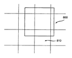
事例に基づく超解像度化のケースでは、回復後イメージまたはビデオフレーム内にホールを生み出すことなく高解像度パッチをシフトするために、クラスタ化中に生成されたイグザンプルパッチは、置換用の低解像度フレーム内のパッチよりも大きくなければならない。例えば、フレーム内の低解像度パッチのサイズがN×Nピクセルである場合、代表的パッチのサイズは、M>NとしてM×Mでなければならない。したがって、1次元での最大パッチシフトはM−Nである。図8を参照すると、拡大パッチが、全般的に参照符号800で示されている。置換用のフレーム内の低解像度パッチ810も示されている。図からわかるように、拡大パッチ800は、他の「フレーム領域」内に延びる。
In case of super-resolution based on patch shifting case, the example patch generated during clustering is used for replacement to shift the high resolution patch without creating holes in the post-recovery image or video frame. Must be larger than the patch in the low resolution frame. For example, if the size of the low resolution patch in the frame is N × N pixels, the size of the representative patch must be M × M where M> N. Therefore, the maximum patch shift in one dimension is MN. Referring to FIG. 8, the enlarged patch is indicated generally by the
本発明者等の現在の事例に基づく超解像度化システムでは、N×Nピクセルサイズを有する1組のパッチに対してクラスタ化プロセスを実行する。しかし、クラスタ化プロセスを行った後、M×Mピクセルサイズを有する、対応する拡大パッチを平均することによって代表的パッチを生成する。拡大パッチは、追加の境界拡張(各次元でM−Nピクセル)を伴うクラスタ化のために使用されるパッチである。境界のパッチについて、フレームの外側のエリアに追加のピクセルを補充することによって拡大パッチを作成する。例えば、ブラックピクセルを補充する、境界のピクセルを複製するなどの、異なる補充の方策を使用することができる。 In our super-resolution system based on our current case, the clustering process is performed on a set of patches having an N × N pixel size. However, after performing the clustering process, a representative patch is generated by averaging the corresponding enlarged patches having an M × M pixel size. A magnification patch is a patch used for clustering with additional boundary expansion (M-N pixels in each dimension). For the boundary patch, create a magnified patch by filling the area outside the frame with additional pixels. Different fill strategies can be used, for example, fill black pixels, duplicate border pixels, etc.
デコーダ側では、パッチ置換およびシフティングプロセスの前に、パッチマッチングのための通常の代表的パッチ(N×Nピクセルブロック)をクロッピングによって拡大パッチから作成する。フレーム回復プロセスの間、低解像度イメージ内の所与のパッチ位置の低解像度パッチを、ライブラリ内の通常の代表的パッチ(N×Nピクセルブロック)とマッチングする。最小の距離を有するライブラリ内のパッチを候補として選択する。次いで、(例えば、図8の)拡大イグザンプルパッチを使用するパッチシフティングプロセスを適用し、拡大イグザンプルパッチの露出部分(すなわち、低解像度パッチを置き換える部分)と、置換用の低解像度パッチ(図3)との間の最小距離が得られるシフト座標を見つける。このことは本質的に、パッチ発見およびパッチシフティングを含む2段階プロセスである。これらのステップを、パッチマッチングステップごとにパッチシフティングも適用するように組み合わせることができ、その結果、最良のパッチ候補および最良のパッチシフト座標を同時に得ることができる。しかし、そのような共同プロセスは、計算コストがはるかに高い。 On the decoder side, before the patch replacement and shifting process, a typical representative patch (N × N pixel block) for patch matching is created from the enlarged patch by cropping. During the frame recovery process, the low resolution patch at a given patch location in the low resolution image is matched with a regular representative patch (N × N pixel block) in the library. Select the patch in the library with the smallest distance as a candidate. Then, a patch shifting process using the enlarged example patch (eg, of FIG. 8) is applied to expose the exposed portion of the enlarged example patch (ie, the portion that replaces the low resolution patch) and the replacement low resolution patch ( Find the shift coordinate that gives the minimum distance between This is essentially a two-step process involving patch discovery and patch shifting. These steps can be combined to apply patch shifting for each patch matching step, so that the best patch candidate and the best patch shift coordinates can be obtained simultaneously. However, such a collaborative process is much more computationally expensive.
ベクトル量子化圧縮応用例では、パッチを位置合せするために使用することのできる低解像度イメージおよび低解像度パッチはない。しかし、本明細書の後で説明する時空的平滑化を図ることにより、パッチシフティングをやはり達成することができる。 In vector quantization compression applications, there are no low resolution images and low resolution patches that can be used to align the patches. However, spatiotemporal smoothing described later in this specification by FIG Rukoto, patch shifting also can be achieved.
時空的平滑化
上記では、空間的および時間的制約を考慮することなく、単純なマッチングプロセスによってパッチシフティングが実現される。その結果、時空的整合性が実施されないので、回復後にアーチファクトが依然として見えることがある。
The spatiotemporal smoothing above, without considering the spatial and temporal constraints, patch shifting is realized by a simple matching process. As a result, artifacts may still be visible after recovery since spatio-temporal consistency is not implemented.
本発明等の現在のシステムでは、その変数が拡大パッチのシフト座標であるコスト関数を最小限に抑えることによって時空的制約が実施される。具体的には、i番目の拡大パッチPiについて、シフト座標はSi=(xi,yi)である。ただしxiはピクセル単位で測定した水平シフトであり、yiは垂直シフトである。空間的制約のみを考慮する場合、コスト関数を以下のように構築することができる。 In current systems, such as the present invention, space-time constraints are implemented by minimizing the cost function whose variables are the shift coordinates of the enlarged patch. Specifically, for the i-th enlarged patch P i , the shift coordinates are S i = (x i , y i ). Where x i is a horizontal shift measured in pixels and y i is a vertical shift. When considering only spatial constraints, the cost function can be constructed as follows:

上式で、Siはi番目のパッチのシフト座標であり、λは重み因子であり、C1は、シフトしたパッチとテンプレートパッチとの間の差を測定するコスト関数である(テンプレートパッチは、事例に基づく超解像度化のケースでは低解像度パッチである)。T(.)が、シフト座標Siに従ってMiのサイズをマッチングするために拡大パッチをシフトし、クロッピングし、小型化する変換であるとして、テンプレートパッチがMiであり、シフトし、クロッピングしたパッチがT(Pi|Si)である場合、C1が Where S i is the shift coordinate of the i-th patch, λ is the weighting factor, and C1 is a cost function that measures the difference between the shifted patch and the template patch (the template patch is In the case of super-resolution based on the case, it is a low resolution patch). T (.) Is shifted to expand the patch to match the size of M i in accordance with a shift coordinates S i, cropping, as a conversion to reduce the size of the template patch is M i, shift, and cropping If the patch is T (P i | S i ), C1 is
と定義される。C2がi番目のパッチの境界ピクセルを使用して定義される。境界エリアをΩと表す。その場合、 Is defined. C2 is defined using the boundary pixel of the i-th patch. The boundary area is represented as Ω. In that case,
![]()
![]()
であり、ただし However,
![]()
![]()
は境界エリアΩ内に制限される距離計算を表す。Iは、最後の反復による回復後ビデオフレームである。C2に関する他の代替コスト関数、例えば、パッチ差を計算するためにピクセルではなくイメージ勾配を使用するコスト関数も使用できることを理解されたい。アルゴリズムは、C1コスト関数のみで式(2)のコスト関数を最小限に抑えることによって初期値S1、S2、...、SMで開始する反復プロセスである。続く反復では、C2関数を使用する。 Represents a distance calculation limited within the boundary area Ω. I is the video frame after recovery by the last iteration. It should be understood that other alternative cost functions for C2, such as a cost function that uses image gradients rather than pixels to calculate patch differences, can also be used. The algorithm uses initial values S 1 , S 2 ,... By minimizing the cost function of equation (2) with only the C1 cost function. . . , S M is an iterative process. In subsequent iterations, the C2 function is used.
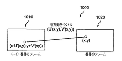
上記の構築は、時間的整合性を考慮に入れない。時間的整合性を考慮する場合、パッチシフティングの前に動きベクトルフィールドを計算しなければならない。本発明の現在のシステムでは、各パッチ位置について前方動きベクトルおよび後方動きベクトルをどちらも計算する。前方動きベクトルは、現フレーム内のパッチの、次のフレーム内の対応するパッチと比較した変位である(図9参照)。後方動きベクトルは、現フレーム内のパッチの、前のフレーム内の対応するパッチと比較した変位である(図10参照)。図9を参照すると、前方動きベクトルが、全般的に参照符号900で示されている。前方動きベクトル900は、i番目のフレーム910および(I+1)番目のフレーム920に対応する。図10を参照すると、後方動きベクトルが、全般的に参照符号1000で示されている。後方動きベクトル1000は、(i−1)番目のフレーム1010およびi番目のフレーム910に対応する。
The above construction does not take into account temporal consistency. If temporal consistency is taken into account, the motion vector field must be calculated before patch shifting. In the current system of the present invention, both forward and backward motion vectors are calculated for each patch position. The forward motion vector is the displacement of the patch in the current frame compared to the corresponding patch in the next frame (see FIG. 9). The backward motion vector is the displacement of the patch in the current frame compared to the corresponding patch in the previous frame (see FIG. 10). Referring to FIG. 9, the forward motion vector is indicated generally by the
時間的整合性を考慮に入れると、コスト関数は以下のようになる。 Taking time consistency into account, the cost function is:
![]()
![]()
上式で、C3は、以下のような時間的整合性を実施するコスト関数である。 Where C3 is a cost function that implements temporal consistency as follows:
上式で、F(Mi)は、その前方動きベクトルに従ってパッチMiに対応する次のフレーム内のパッチである。パッチMiの左上隅の座標が(x,y)である場合、次のビデオフレーム内の対応するパッチの左上隅の座標は、(x+U(x,y),y+V(x,y))であるべきである(図9)。同様に、B(Mi)は、その後方動きベクトルに従ってパッチMiに対応する前のフレーム内のパッチである。 Where F (M i ) is the patch in the next frame corresponding to patch M i according to its forward motion vector. If the coordinates of the upper left corner of the patch M i is (x, y), the coordinates of the upper left corner of the corresponding patch in the next video frame, with (x + U (x, y ), y + V (x, y)) Should be (Figure 9). Similarly, B (M i ) is the patch in the previous frame corresponding to patch M i according to its backward motion vector.
拡大パッチのシフト座標Siは、テンプレート(i番目の低解像度パッチ)およびその隣接エリア(i番目のパッチの境界ピクセル)のみに依存するので、式(3)のコスト関数は、実際にはパッチ上のマルコフ確率場(MRF)を定義する。マルコフ確率場の最小化は、限定はしないが、例えば、勾配降下、確率伝播、モンテカルロなどの様々な手法によって実現することができる。本発明者等の現在のシステムでは、勾配降下手法が効率的であり、満足の行く結果を与えるので、勾配降下手法を使用する。最小化手順は、以下のような反復プロセスである(図11)。
1.時空的制約なしにパッチをシフトすることによってすべてのフレーム内のすべてのパッチのシフト座標を初期化する。このことは、C2項およびC3項のない式(3)のコスト関数を最小限に抑えることと同等である。
2.各フレームについて、C2項およびC3項を有する式(3)のコスト関数を最小限に抑える。その後、選択したパッチおよびシフト座標を使用して、高解像度フレームを回復する。
3.停止条件を満たす場合、アルゴリズムから出る。そうでない場合、ステップ2に戻る。
Since the shift coordinate S i of the enlarged patch depends only on the template (i-th low-resolution patch) and its adjacent area (boundary pixel of the i-th patch), the cost function of Equation (3) is actually a patch Define the above Markov random field (MRF). The Markov random field can be minimized by various methods such as, for example, gradient descent, probability propagation, and Monte Carlo. In our current system, gradient descent techniques are used because they are efficient and give satisfactory results. The minimization procedure is an iterative process as follows (FIG. 11).
1. Initialize the shift coordinates of all patches in all frames by shifting the patches without space-time constraints. This is equivalent to minimizing the cost function of equation (3) without C2 and C3 terms.
2. For each frame, minimize the cost function of equation (3) with C2 and C3 terms. The selected patch and shift coordinates are then used to recover the high resolution frame.
3. If the stop condition is met, exit the algorithm. If not, return to Step 2.
様々な停止条件を使用することができる。1つの可能な選択肢は、最後の反復と現反復の合計コストの差が一定のしきい値未満であるときにアルゴリズムを停止させることである。 Various stopping conditions can be used. One possible option is to stop the algorithm when the difference between the total cost of the last iteration and the current iteration is below a certain threshold.
本原理の一実施形態では、本発明者等の提案する方法の最適化フレームワークがマルコフ確率場(MRF)に基づくことに留意されたい。前述の第1の従来技術の手法は、MRFフレームワークを使用してパッチの選択を最適化したが、本発明者等は、MRFを使用してパッチをシフトし、ベクトル量子化誤差によって引き起こされるアーチファクトを最小限に抑えることにさらに留意されたい。 It should be noted that in one embodiment of the present principles, the optimization framework of the method proposed by the inventors is based on a Markov random field (MRF). Although the first prior art approach described above optimized patch selection using the MRF framework, we shifted the patch using MRF and caused by vector quantization errors. Note further that artifacts are minimized.
図11を参照すると、パッチングシフティングのための例示的方法が、全般的に参照符号1100で示されている。方法1100は開始ブロック1105を含み、開始ブロック1105は機能ブロック1110に制御を渡す。機能ブロック1110は低解像度フレームおよび拡大イグザンプルパッチを入力し、機能ブロック1115に制御を渡す。機能ブロック1115は、すべてのフレームに関するすべてのパッチのシフト座標を初期化し、機能ブロック1120に制御を渡す。機能ブロック1120は、コスト関数を最小限に抑えて最良のシフト座標を見つけ、機能ブロック1125に制御を渡す。機能ブロック1125は、パッチおよび最良のシフト座標を使用して高解像度フレームを回復し、判定ブロック1130に制御を渡す。判定ブロック1130は、コスト関数が収束したか否かを判定する。収束した場合、機能ブロック1135に制御を渡す。収束しない場合、機能ブロック1120に制御を返す。機能ブロック1135は、最良のシフト座標を出力し、終了ブロック1199に制御を渡す。
Referring to FIG. 11, an exemplary method for patching shifting is indicated generally by the
サブピクセルパッチシフティング
オブジェクトまたは背景の動きが非常に小さい場合、前述の時空的制約を使用する場合であっても、ジッタリングアーチファクトがまだ見えることになる。サブピクセルパッチシフティングを使用して、パッチ位置合せをより正確にする。サブピクセルパッチシフティングを使用するアルゴリズムは、時空的平滑化を図ることに関して上記で説明したものとほぼ同じである。違いは、シフト座標が分数値、例えば1/2ピクセル、1/3ピクセルなどを取ることである。
Sub-pixel patch shifting If the motion of the object or background is very small, jittering artifacts will still be visible even when using the spatio-temporal constraints described above. Sub-pixel patch shifting is used to make patch alignment more accurate. Algorithms that use sub-pixel patch shifting is substantially the same as those described above with respect to FIG Rukoto spatiotemporal smoothing. The difference is that the shift coordinates take fractional values, for example 1/2 pixel, 1/3 pixel, etc.
サブピクセルパッチシフティングを使用することは、式(3)のMRFコスト関数についてより多くの状態数(すなわち、シフト座標の空間のサイズ)が存在し、したがってサブピクセルパッチシフティングが通常のパッチシフティングよりも複雑となることを意味する。計算複雑さを低減する一方法は、以下のような階層型マッチング方式を使用することである。まず、ピクセルパッチシフティング方式を使用して、パッチの位置を概算で求め、次いで、狭い範囲でのサブピクセルパッチシフティングが続き、パッチ位置を改善する。 Using sub-pixel patch shifting has a higher number of states (ie, the size of the space of the shift coordinates) for the MRF cost function of Equation (3), so that sub-pixel patch shifting is normal patch shifting. It means that it is more complicated than Ting. One way to reduce computational complexity is to use a hierarchical matching scheme as follows. First, the patch location is approximated using a pixel patch shifting scheme, followed by sub-pixel patch shifting over a narrow area to improve the patch location.
より良好な代表的パッチの生成
今までのところは、ビデオ回復段階中にパッチシフティングを適用するだけである。しかし、クラスタ化プロセス中により良好な代表的パッチを生成するためにパッチシフティングを使用することもできる。
Better representative patch generation So far, only patch shifting is applied during the video recovery phase. However, patch shifting can also be used to generate better representative patches during the clustering process.
代表的パッチは通常、クラスタ化中にクラスタ内のすべてのパッチを平均することによって生成される。パッチ内のオブジェクト縁部が平均化の前に位置合せされない場合、平均化プロセスの結果、一般には、得られるパッチイメージの解像度は低くなる。したがって、オブジェクト縁部をより良好に保持することができるように、平均化プロセスの前にパッチシフティングを適用してパッチを位置合せすることができる。各クラスタについて、以下の反復手順によって位置合せを実現することができる。
1.クラスタ内のすべてのパッチを平均し、クラスタの初期代表的パッチを得る。
2.クラスタ内のパッチのうちの所与の各パッチを代表的パッチとマッチングして、(例えば、ユークリッド距離などを使用して)全体の差を最小限に抑えることにより、クラスタ内の各パッチを代表的パッチに位置合せする。
3.すべてのパッチがゼロシフトを有する場合、アルゴリズムは停止し、代表的パッチを出力する。そうでない場合、シフトしたパッチを平均することによって代表的パッチを再計算し、ステップ2に戻る。
A representative patch is usually generated by averaging all patches in the cluster during clustering. If the object edges in the patch are not aligned before averaging, the averaging process generally results in a lower resolution of the resulting patch image. Therefore, patch shifting can be applied prior to the averaging process to align the patches so that the object edges can be better held. For each cluster, alignment can be achieved by the following iterative procedure.
1. Average all patches in the cluster to get the initial representative patch for the cluster.
2. Represent each patch in the cluster by matching each given patch in the cluster with a representative patch and minimizing the overall difference (eg, using Euclidean distance, etc.) Align to the target patch.
3. If all patches have a zero shift, the algorithm stops and outputs a representative patch. If not, recalculate the representative patch by averaging the shifted patches and return to step 2.
前述の手法とは別に、より良好な代表的パッチを生成することは、例えば、第1の例示的手法や第2の例示的手法などの他の手法でも実現することができる。第1の例示的手法では、クラスタ内のパッチを平均するのではなく、平均パッチから最小の距離を有するパッチのうちの1つをクラスタから選ぶことができる。第2の例示的手法では、クラスタ内のパッチを平均するではなく、クラスタ内のパッチのうちの一部のみを使用して平均化を実行すると共に、クラスタ中心(すなわち、平均パッチ)から逸脱し過ぎているアウトライアパッチを除外することができる。 Apart from the above-described method, generating a better representative patch can also be realized by other methods such as the first exemplary method and the second exemplary method. In the first exemplary approach, instead of averaging the patches in the cluster, one of the patches having the smallest distance from the average patch can be selected from the cluster. In the second exemplary approach, rather than averaging the patches in the cluster, only some of the patches in the cluster are used to perform the averaging and deviate from the cluster center (ie, the average patch). You can exclude outlier patches that have passed.
より一般的なパッチ変換への拡張
パッチシフティングは、一般的なパッチ幾何学的変換の特殊ケースである。したがって、パッチシフティングの概念は、限定はしないが、ズームイン/アウト、回転、射影変換などを含むより一般的な幾何学的変換に対処する、より汎用の変換に一般化することができる。こうした変換を組み込むアルゴリズムは、シフト座標をより一般的な変換パラメータで置き換えることにより、時空的平滑化を図ることに関して本明細書の上記で与えたアルゴリズムと同様である。そのようなパラメータの例は、限定はしないが、変換パラメータ、回転パラメータ、投射パラメータなどを含む。しかし、一般的なパッチ変換の主な問題は、計算複雑さがパッチシフティングよりもずっと高くなることである。
Extensions to more general patch transformations Patch shifting is a special case of general patch geometric transformations. Thus, the concept of patch shifting can be generalized to more general-purpose transformations that address more general geometric transformations including but not limited to zoom in / out, rotation, projective transformations, and the like. Algorithm incorporating such transformations, by replacing the shift coordinates in a more general transformation parameters are similar to the algorithm given herein above with respect to FIG Rukoto spatiotemporal smoothing. Examples of such parameters include, but are not limited to, conversion parameters, rotation parameters, projection parameters, and the like. However, the main problem with general patch conversion is that the computational complexity is much higher than patch shifting.
図12を参照すると、改良型代表的パッチを生成する例示的方法が、全般的に参照符号1200で示されている。方法1200は開始ブロック1205を含み、開始ブロック1205は機能ブロック1210に制御を渡す。機能ブロック1210はクラスタおよびそのパッチを入力し、機能ブロック1215に制御を渡す。機能ブロック1215は、初期の代表的パッチを計算し、機能ブロック1220に制御を渡す。機能ブロック1220は、パッチを代表的パッチと位置合せし、判定ブロック1225に制御を渡す。判定ブロック1225は、すべてのパッチがゼロシフトを有するか否かを判定する。そうである場合、機能ブロック1230に制御を渡す。そうでない場合、機能ブロック1235に制御を渡す。機能ブロック1230は代表的パッチを出力し、終了ブロック1299に制御を渡す。機能ブロック1235は代表的パッチを再計算し、機能ブロック1220に制御を返す。
Referring to FIG. 12, an exemplary method for generating an improved representative patch is indicated generally by the
実験結果
本発明者等は、例に基づくビデオ超解像度応用例について様々なビデオに対してパッチシフティングアルゴリズムをテストした。結果は、サブピクセルシフトおよびMRF最適化を伴うパッチシフティングアルゴリズムが、動きによって引き起こされるジッタリングアーチファクトを著しく低減することを示している。
Experimental Results We tested the patch shifting algorithm on various videos for example-based video super-resolution applications. The results show that the patch shifting algorithm with sub-pixel shift and MRF optimization significantly reduces jittering artifacts caused by motion.
様々な実施形態および変形形態
1.MRFベースのフレームワークを何らかの他のコスト関数ベースの定式化で置き換えることができる。
2.様々な最適化方法によって式(3)のMRFコスト関数を最小限に抑えることができる。
3.式(3)の第2の項を他の境界条件で置き換えることができる。
4.式(3)の第3の項について様々な(異なる)定式化を使用することができる。
5.より良好な代表的パッチを生成することに関して本明細書で説明した方法の、様々な他の方法および手法での置換え。
次に、その一部を上記で述べた、本発明の多くの付随する利点/特徴のうちの一部の説明を与える。例えば、1つの利点/特徴は、入力ビデオシーケンスから、1つまたは複数の高解像度置換パッチを生成するパッチジェネレータを有する装置である。1つまたは複数の高解像度置換パッチは、入力ビデオシーケンスの再構築中に1つまたは複数の低解像度パッチを置き換えるためのものである。パッチジェネレータは、パッチ空間シフティングプロセスに対応するデータを使用して、1つまたは複数の高解像度置換パッチを生成する。パッチ空間シフティングプロセスは、1つまたは複数の高解像度置換パッチ内の動き誘導ベクトル量子化誤差によって引き起こされるジッタの多いアーチファクトを低減するためのものである。データは、パッチ空間シフティングプロセスでの使用に適するようにするために1つまたは複数の低解像度パッチのパッチサイズよりも大きいパッチサイズを有するような1つまたは複数の高解像度置換パッチを生成するように、1つまたは複数の高解像度置換パッチのパッチサイズを少なくとも導出するためのものである。
Various embodiments and variations The MRF-based framework can be replaced with some other cost function-based formulation.
2. Various optimization methods can minimize the MRF cost function of Equation (3).
3. The second term in equation (3) can be replaced with other boundary conditions.
4). Various (different) formulations can be used for the third term of equation (3).
5. Replacement of the methods described herein with respect to generating better representative patches with various other methods and techniques.
A description will now be given of some of the many attendant advantages / features of the present invention, some of which have been mentioned above. For example, one advantage / feature is an apparatus having a patch generator that generates one or more high resolution replacement patches from an input video sequence. The one or more high resolution replacement patches are for replacing the one or more low resolution patches during reconstruction of the input video sequence. The patch generator uses the data corresponding to the patch space shifting process to generate one or more high resolution replacement patches. The patch space shifting process is for reducing jittery artifacts caused by motion induced vector quantization errors in one or more high resolution replacement patches. The data generates one or more high-resolution replacement patches that have a patch size that is larger than the patch size of one or more low-resolution patches to make it suitable for use in a patch space shifting process. As such, it is for deriving at least the patch size of one or more high resolution replacement patches.
別の利点/特徴は、上述のようなパッチジェネレータを有する装置であり、動き誘導ベクトル量子化誤差が、1つまたは複数の高解像度置換パッチの生成中に適用される量子化プロセスによって引き起こされる。 Another advantage / feature is an apparatus having a patch generator as described above, where motion induced vector quantization errors are caused by the quantization process applied during the generation of one or more high resolution replacement patches.
さらに別の利点/特徴は、パッチジェネレータを有する装置であり、上述のように、動き誘導ベクトル量子化誤差が、1つまたは複数の高解像度置換パッチの生成中に適用される量子化プロセスによって引き起こされ、量子化プロセスが、入力ビデオシーケンスから抽出された複数のパッチに適用されるクラスタ化プロセスに対応し、クラスタ化プロセスが、1つまたは複数の基準に基づく同様の特性を有する複数のパッチのうちのパッチを互いにグループ化するためのものであり、1つまたは複数の高解像度置換パッチが、複数のパッチのうちのパッチから導出される。 Yet another advantage / feature is an apparatus having a patch generator where, as described above, motion induced vector quantization errors are caused by a quantization process applied during the generation of one or more high resolution replacement patches. The quantization process corresponds to a clustering process applied to a plurality of patches extracted from an input video sequence, and the clustering process includes a plurality of patches having similar characteristics based on one or more criteria. The patches are for grouping one another, and one or more high resolution replacement patches are derived from the patches of the plurality of patches.
さらに別の利点/特徴は、パッチジェネレータを有する装置であり、量子化プロセスが、入力ビデオシーケンスから抽出された複数のパッチに適用されるクラスタ化プロセスに対応し、クラスタ化プロセスが、1つまたは複数の基準に基づく同様の特性を有する複数のパッチのうちのパッチを互いにグループ化するためのものであり、上述のように、1つまたは複数の高解像度置換パッチが、複数のパッチのうちのパッチから導出され、クラスタ化プロセスが、同一のクラスタ内の複数のパッチのうちのパッチを平均することを含み、同一のクラスタ内に含めるために複数のパッチのうちのパッチを選択することに続いて、同一のクラスタ内の複数のパッチのうちのパッチの平均化の前に、平均化に備えて複数のパッチのうちのパッチ内のオブジェクト縁部を位置合せするために、パッチ空間シフティングプロセスが、複数のパッチのうちのパッチに適用される。 Yet another advantage / feature is an apparatus having a patch generator, wherein the quantization process corresponds to a clustering process applied to multiple patches extracted from an input video sequence, and the clustering process includes one or more For grouping together patches of a plurality of patches having similar characteristics based on a plurality of criteria, and as described above, one or more high-resolution replacement patches are included in the plurality of patches Derived from the patches, the clustering process includes averaging the patches of the plurality of patches in the same cluster, and following selecting the patches of the plurality of patches for inclusion in the same cluster Before patch averaging of multiple patches in the same cluster, the options in the patches of multiple patches are prepared for averaging. To align the object edge, the patch spatial shifting process is applied to the patch of the plurality of patches.
さらに、別の利点/特徴は、パッチジェネレータを有する装置であり、クラスタ化プロセスが、同一のクラスタ内の複数のパッチのうちのパッチを平均することを含み、同一のクラスタ内に含めるために複数のパッチのうちのパッチを選択することに続いて、同一のクラスタ内の複数のパッチのうちのパッチの平均化の前に、上述のように、平均化に備えて複数のパッチのうちのパッチ内のオブジェクト縁部を位置合せするために、パッチ空間シフティングプロセスが、複数のパッチのうちのパッチに適用され、同一のクラスタ内の複数のパッチのうちのパッチの一部だけが、クラスタ中心からの対応するパッチ距離に基づいて平均される。 Yet another advantage / feature is an apparatus having a patch generator, where the clustering process includes averaging patches of multiple patches in the same cluster, multiple for inclusion in the same cluster. Following the selection of the patches of the patches, the patches of the patches of the plurality of patches in the same cluster are prior to averaging of the patches of the patches of the plurality of patches in preparation for averaging as described above. A patch space shifting process is applied to the patches of the plurality of patches to align the object edges within, and only some of the patches of the plurality of patches in the same cluster are cluster-centered. Is averaged based on the corresponding patch distance from.
さらに、別の利点/特徴は、上述のようなパッチジェネレータを有する装置であり、動き誘導ベクトル量子化誤差が、入力ビデオシーケンスの再構築中に実行されるパッチ置換プロセスによって引き起こされる。 Yet another advantage / feature is an apparatus having a patch generator as described above, where motion induced vector quantization errors are caused by the patch replacement process performed during reconstruction of the input video sequence.
さらに、別の利点/特徴は、上述のようなパッチジェネレータを有する装置であり、装置は、入力ビデオシーケンスから1つまたは複数の小型化ピクチャを生成するダウンサイザと、高解像度置換パッチおよび1つまたは複数の小型化ピクチャを、結果として得られるビットストリームに符号化する、パッチジェネレータおよびダウンサイザと信号通信する1つまたは複数のビデオエンコーダとをさらに含む。 Yet another advantage / feature is an apparatus having a patch generator as described above, wherein the apparatus includes a downsizer that generates one or more miniaturized pictures from an input video sequence, a high resolution replacement patch and one or more It further includes a patch generator and one or more video encoders in signal communication with the downsizer that encode the plurality of miniaturized pictures into the resulting bitstream.
さらに、別の利点/特徴は、上述のようなパッチジェネレータを有する装置であり、方法がビデオエンコーダで実行される。 Yet another advantage / feature is an apparatus having a patch generator as described above, wherein the method is performed with a video encoder.
本明細書の教示に基づいて、本原理のこれらおよび他の特徴および利点を当業者は容易に確認することができる。ハードウェア、ソフトウェア、ファームウェア、専用プロセッサ、またはそれらの組合せの様々な形態で本原理の教示を実施できることを理解されたい。 Based on the teachings herein, one of ordinary skill in the art can readily ascertain these and other features and advantages of the present principles. It should be understood that the teachings of the present principles can be implemented in various forms of hardware, software, firmware, special purpose processors, or combinations thereof.
最も好ましくは、本原理の教示は、ハードウェアとソフトウェアの組合せとして実装される。さらに、ソフトウェアをプログラム記憶ユニット上に有形に具体化されたアプリケーションプログラムとして実装することができる。アプリケーションプログラムは、任意の適切なアーキテクチャを備えるマシンにアップロードし、実行することができる。好ましくは、マシンは、1つまたは複数の中央演算処理装置(「CPU」)、ランダムアクセスメモリ(「RAM」)、入出力(「I/O」)インターフェースなどのハードウェアを有するコンピュータプラットフォーム上に実装される。コンピュータプラットフォームはまた、オペレーティングシステムおよびマイクロ命令コードをも含むことができる。本明細書に記載の様々なプロセスおよび機能は、CPUによって実行することのできる、マイクロ命令コードの一部、もしくはアプリケーションプログラムの一部、またはそれらの任意の組合せでよい。さらに、追加のデータ記憶ユニットやプリンティングユニットなどの様々な他の周辺ユニットをコンピュータプラットフォームに接続することができる。 Most preferably, the teachings of the present principles are implemented as a combination of hardware and software. Furthermore, the software can be implemented as an application program tangibly embodied on the program storage unit. Application programs can be uploaded and executed on machines with any suitable architecture. Preferably, the machine is on a computer platform having hardware such as one or more central processing units (“CPU”), random access memory (“RAM”), input / output (“I / O”) interfaces, etc. Implemented. The computer platform can also include an operating system and microinstruction code. The various processes and functions described herein may be part of microinstruction code, part of an application program, or any combination thereof that can be executed by a CPU. In addition, various other peripheral units may be connected to the computer platform such as an additional data storage unit and a printing unit.
添付の図面に示す構成システム構成要素および方法の一部が好ましくはソフトウェアで実装されるので、システム構成要素またはプロセス機能ブロック間の実際の接続は、本原理がプログラムされる方式に応じて異なることがあることをさらに理解されたい。本明細書の教示が与えられると、本原理のこれらおよび類似の実装または構成を当業者は企図することができることになる。 Since some of the configuration system components and methods shown in the accompanying drawings are preferably implemented in software, the actual connections between system components or process functional blocks will vary depending on how the principles are programmed. I want you to understand further that there is. Given the teachings herein, one of ordinary skill in the related art will be able to contemplate these and similar implementations or configurations of the present principles.
添付の図面を参照しながら本明細書で例示的実施形態を説明したが、本原理がこうした厳密な実施形態に限定されず、本原理の範囲または趣旨から逸脱することなく、当業者は本原理の中で様々な変更および修正を実施できることを理解されたい。すべてのそのような変更および修正は、添付の特許請求の範囲に記載の本原理の範囲内に包含されるものとする。
本発明は以下の態様を含む。
(付記1)
入力ビデオシーケンスから、1つまたは複数の高解像度置換パッチを生成するパッチジェネレータ(505)であって、前記1つまたは複数の高解像度置換パッチが、前記入力ビデオシーケンスの再構築中に1つまたは複数の低解像度パッチを置き換えるためのものである、パッチジェネレータ(505)を備える装置であって、
前記パッチジェネレータ(505)は、パッチ空間シフティングプロセスに対応するデータを使用して、1つまたは複数の高解像度置換パッチを生成し、前記パッチ空間シフティングプロセスは、前記1つまたは複数の高解像度置換パッチ内の動き誘導ベクトル量子化誤差によって引き起こされるジッタの多いアーチファクトを低減するためのものであり、前記データは、前記パッチ空間シフティングプロセスでの使用に適するようにするために前記1つまたは複数の低解像度パッチのパッチサイズよりも大きいパッチサイズを有するような前記1つまたは複数の高解像度置換パッチを生成するように、前記1つまたは複数の高解像度置換パッチのパッチサイズを少なくとも導出するためのものである、前記装置。
(付記2)
前記動き誘導ベクトル量子化誤差が、前記1つまたは複数の高解像度置換パッチの生成中に適用される量子化プロセスによって引き起こされる、付記1に記載の装置。
(付記3)
前記量子化プロセスが、前記入力ビデオシーケンスから抽出された複数のパッチに適用されるクラスタ化プロセスに対応し、前記クラスタ化プロセスが、1つまたは複数の基準に基づく同様の特性を有する前記複数のパッチのうちのパッチを互いにグループ化するためのものであり、前記1つまたは複数の高解像度置換パッチが、前記複数のパッチのうちの前記パッチから導出される、付記2に記載の装置。
(付記4)
前記クラスタ化プロセスが、同一のクラスタ内の前記複数のパッチのうちの前記パッチを平均することを含み、前記同一のクラスタ内に含めるために前記複数のパッチのうちの前記パッチを選択することに続いて、前記同一のクラスタ内の前記複数のパッチのうちの前記パッチの平均化の前に、前記平均化に備えて前記複数のパッチのうちの前記パッチ内のオブジェクト縁部を位置合せするために、前記パッチ空間シフティングプロセスが、前記複数のパッチのうちの前記パッチに適用される、付記3に記載の装置。
(付記5)
前記複数のパッチのうちの前記パッチの一部だけが、クラスタ中心からの対応するパッチ距離に基づいて平均される、付記4に記載の装置。
(付記6)
前記動き誘導ベクトル量子化誤差が、前記入力ビデオシーケンスの再構築中に実行されるパッチ置換プロセスによって引き起こされる、付記1に記載の装置。
(付記7)
前記入力ビデオシーケンスから1つまたは複数の小型化ピクチャを生成するダウンサイザ(520)と、
前記高解像度置換パッチおよび前記1つまたは複数の小型化ピクチャを、結果として得られるビットストリームに符号化する、前記パッチジェネレータおよび前記ダウンサイザと信号通信する1つまたは複数のビデオエンコーダ(515、525)と、
をさらに備える、付記1に記載の装置。
(付記8)
前記方法がビデオエンコーダで実行される、付記1に記載の装置。
(付記9)
プロセッサを使用して実行される方法であって、
入力ビデオシーケンスから、1つまたは複数の高解像度置換パッチを生成するステップであって、前記1つまたは複数の高解像度置換パッチが、前記入力ビデオシーケンスの再構築中に1つまたは複数の低解像度パッチを置き換えるためのものである、ステップ
を含み、
前記生成するステップは、パッチ空間シフティングプロセスに対応するデータを使用して、前記1つまたは複数の高解像度置換パッチを生成し、前記パッチ空間シフティングプロセスは、前記1つまたは複数の高解像度置換パッチ内の動き誘導ベクトル量子化誤差によって引き起こされるジッタの多いアーチファクトを低減するためのものであり、前記データは、前記パッチ空間シフティングプロセスでの使用に適するようにするために前記1つまたは複数の低解像度パッチのパッチサイズよりも大きいパッチサイズを有するような前記1つまたは複数の高解像度置換パッチを生成するように、前記1つまたは複数の高解像度置換パッチのパッチサイズを少なくとも導出するためのものである、前記方法。
(付記10)
前記動き誘導ベクトル量子化誤差は、前記1つまたは複数の高解像度置換パッチの生成中に適用される量子化プロセスによって引き起こされる、付記9に記載の方法。
(付記11)
前記量子化プロセスが、前記入力ビデオシーケンスから抽出された複数のパッチに適用されるクラスタ化プロセス(1315)に対応し、前記クラスタ化プロセス(1315)が、1つまたは複数の基準に基づく同様の特性を有する前記複数のパッチのうちのパッチを互いにグループ化するためのものであり、前記1つまたは複数の高解像度置換パッチが、前記複数のパッチのうちの前記パッチから導出される、付記10に記載の方法。
(付記12)
前記クラスタ化プロセス(1315)が、同一のクラスタ内の前記複数のパッチのうちの前記パッチを平均することを含み、前記同一のクラスタ内に含めるために前記複数のパッチのうちの前記パッチを選択することに続いて、前記同一のクラスタ内の前記複数のパッチのうちの前記パッチの平均化の前に、前記平均化に備えて前記複数のパッチのうちの前記パッチ内のオブジェクト縁部を位置合せするために、前記パッチ空間シフティングプロセスが、前記複数のパッチのうちの前記パッチに適用される、付記11に記載の方法。
(付記13)
前記複数のパッチのうちの前記パッチの一部だけが、クラスタ中心からの対応するパッチ距離に基づいて平均される、付記12に記載の方法。
(付記14)
前記動き誘導ベクトル量子化誤差が、前記入力ビデオシーケンスの再構築中に実行されるパッチ置換プロセスによって引き起こされる、付記9に記載の方法。
(付記15)
前記高解像度置換パッチ(1325)および前記1つまたは複数の小型化ピクチャを、結果として得られるビットストリーム(1335)に符号化するステップをさらに含む、付記9に記載の方法。
(付記16)
ビデオエンコーダで実行される、付記9に記載の方法。
(付記17)
動き誘導ベクトル量子化誤差を有する1つまたは複数の高解像度置換パッチを受け取り、前記1つまたは複数の高解像度置換パッチを少なくとも空間的にシフトして、前記動き誘導ベクトル量子化誤差によって引き起こされるジッタの多いアーチファクトを低減するパッチシフタ(560)であって、前記1つまたは複数の高解像度置換パッチが、入力ビデオシーケンスに対応し、入力ビデオシーケンスから導出されるパッチシフタ(560)と、
前記入力ビデオシーケンスに対応し、前記入力ビデオシーケンスから導出された1つまたは複数の空間的にシフトした高解像度置換パッチおよび1つまたは複数の小型化ピクチャを使用して前記入力ビデオシーケンスを再構築する、前記パッチシフタと信号通信するピクチャ再構築デバイス(560)と、
を備える、装置。
(付記18)
前記入力ビデオシーケンスが、ビデオ圧縮用のベクトル量子化ベースの圧縮プロセス、例に基づくビデオ超解像度プロセス、ビデオ要約プロセス、およびビデオプルーニングプロセスのうちの少なくとも1つで再構築される、付記17に記載の装置。
(付記19)
前記高解像度置換パッチが、空間的制約および時間的制約を使用して、それぞれ空間的および時間的にシフトされる、付記17に記載の装置。
(付記20)
マルコフ確率場が使用され、再構築後ビデオシーケンス中の時空的平滑度が実施される、付記17に記載の装置。
(付記21)
前記マルコフ確率場がコスト関数として実装され、パッチシフト座標がコスト関数の変数として使用され、前記1つまたは複数の高解像度置換パッチのうちの対応するものに関する、対応するシフトが求められる、付記20に記載の装置。
(付記22)
空間シフティングがサブピクセルパッチシフティングを含み、前記ジッタの多いアーチファクトをさらに低減する、付記17に記載の装置。
(付記23)
前記サブピクセルパッチシフティングが階層型パッチマッチングプロセスで使用され、前記階層型パッチマッチングプロセスでは、ピクセルパッチシフティングプロセスを使用して、前記1つまたは複数の高解像度置換パッチのうちの1つによって置き換えられるべき低解像度パッチの位置を推定し、次いでサブピクセルパッチシフティングプロセスを実行して、推定を改善し、前記サブピクセルパッチシフティングプロセスでは、前記ピクセルパッチシフティングプロセスよりも狭い範囲を使用する、付記22に記載の装置。
(付記24)
ビットストリームから前記高解像度置換パッチおよび前記1つまたは複数の小型化ピクチャを復号化する前記パッチシフタと信号通信するビデオデコーダをさらに備える、付記17に記載の装置。
(付記25)
ビデオデコーダに含まれる、付記17に記載の装置。
(付記26)
プロセッサを使用して実行される方法であって、
動き誘導ベクトル量子化誤差を有する1つまたは複数の高解像度置換パッチを受け取るステップと、
前記1つまたは複数の高解像度置換パッチを少なくとも空間的にシフトして、前記動き誘導ベクトル量子化誤差によって引き起こされるジッタの多いアーチファクトを低減するステップ(1520)であって、前記1つまたは複数の高解像度置換パッチが、入力ビデオシーケンスに対応し、入力ビデオシーケンスから導出されるステップ(1520)と、
前記入力ビデオシーケンスに対応し、前記入力ビデオシーケンスから導出された1つまたは複数の空間的にシフトした高解像度置換パッチおよび1つまたは複数の小型化ピクチャを使用して前記入力ビデオシーケンスを再構築するステップ(1525)と、
を含む、前記方法。
(付記27)
前記入力ビデオシーケンスが、ビデオ圧縮用のベクトル量子化ベースの圧縮プロセス、例に基づくビデオ超解像度プロセス、ビデオ要約プロセス、およびビデオプルーニングプロセスのうちの少なくとも1つで再構築される、付記26に記載の方法。
(付記28)
前記高解像度置換パッチが、空間的制約および時間的制約を使用して、それぞれ空間的および時間的にシフトされる、付記26に記載の方法。
(付記29)
マルコフ確率場が使用され、再構築後ビデオシーケンス中の時空的平滑度が実施される、付記26に記載の方法。
(付記30)
前記マルコフ確率場がコスト関数として実装され、パッチシフト座標が前記コスト関数の変数として使用され、前記1つまたは複数の高解像度置換パッチのうちの対応するものに関する、対応するシフトが求められる、付記29に記載の方法。
(付記31)
空間シフティングがサブピクセルパッチシフティングを含み、前記ジッタの多いアーチファクトをさらに低減する、付記26に記載の方法。
(付記32)
前記サブピクセルパッチシフティングが階層型パッチマッチングプロセスで使用され、前記階層型パッチマッチングプロセスでは、ピクセルパッチシフティングプロセスを使用して、前記1つまたは複数の高解像度置換パッチのうちの1つによって置き換えられるべき低解像度パッチの位置を推定し、次いでサブピクセルパッチシフティングプロセスを実行して、推定を改善し、前記サブピクセルパッチシフティングプロセスでは、前記ピクセルパッチシフティングプロセスよりも狭い範囲を使用する、付記31に記載の方法。
(付記33)
ビットストリームから前記高解像度置換パッチおよび前記1つまたは複数の小型化ピクチャを復号化するステップ(1410)をさらに含む、付記26に記載の方法。
(付記34)
ビデオデコーダで実行される、付記26に記載の方法。
(付記35)
その上に符号化されたビデオ信号データを有するコンピュータ可読記憶媒体であって、
入力ビデオシーケンスから生成された1つまたは複数の高解像度置換を含み、前記1つまたは複数の高解像度置換パッチは、前記入力ビデオシーケンスの再構築中に1つまたは複数の低解像度パッチを置き換えるためのものであり、
前記1つまたは複数の高解像度置換パッチが、パッチ空間シフティングプロセスに対応するデータを使用して生成され、前記パッチ空間シフティングプロセスが、前記1つまたは複数の高解像度置換パッチ内の動き誘導ベクトル量子化誤差によって引き起こされるジッタの多いアーチファクトを低減するためのものであり、前記データが、前記パッチ空間シフティングプロセスでの使用に適するようにするために前記1つまたは複数の低解像度パッチのパッチサイズよりも大きいパッチサイズを有するような前記1つまたは複数の高解像度置換パッチを生成するように、前記1つまたは複数の高解像度置換パッチのパッチサイズを少なくとも導出するためのものである、前記コンピュータ可読記憶媒体。
While exemplary embodiments have been described herein with reference to the accompanying drawings, the present principles are not limited to these exact embodiments and those skilled in the art will recognize the principles without departing from the scope or spirit of the principles. It should be understood that various changes and modifications can be made therein. All such changes and modifications are intended to be included within the scope of the present principles as set forth in the appended claims.
The present invention includes the following aspects.
(Appendix 1)
A patch generator (505) that generates one or more high-resolution replacement patches from an input video sequence, wherein the one or more high-resolution replacement patches are one or more during reconstruction of the input video sequence An apparatus comprising a patch generator (505) for replacing a plurality of low resolution patches,
The patch generator (505) uses data corresponding to a patch space shifting process to generate one or more high resolution replacement patches, the patch space shifting process including the one or more high resolution replacement patches. In order to reduce jittery artifacts caused by motion-induced vector quantization errors in a resolution replacement patch, the data is used to make it suitable for use in the patch space shifting process. Or at least deriving the patch size of the one or more high-resolution replacement patches so as to generate the one or more high-resolution replacement patches having a patch size that is larger than the patch size of the plurality of low-resolution patches. Said device.
(Appendix 2)
The apparatus of claim 1, wherein the motion induced vector quantization error is caused by a quantization process applied during generation of the one or more high resolution replacement patches.
(Appendix 3)
The quantization process corresponds to a clustering process applied to a plurality of patches extracted from the input video sequence, the clustering process having the same characteristics based on one or more criteria The apparatus of claim 2 for grouping patches of a patch together, wherein the one or more high resolution replacement patches are derived from the patch of the plurality of patches.
(Appendix 4)
The clustering process includes averaging the patches of the plurality of patches in the same cluster, and selecting the patches of the plurality of patches for inclusion in the same cluster. Subsequently, prior to averaging the patches of the plurality of patches in the same cluster, to align object edges within the patches of the plurality of patches in preparation for the averaging The apparatus according to claim 3, wherein the patch space shifting process is applied to the patch of the plurality of patches.
(Appendix 5)
The apparatus of claim 4, wherein only a part of the plurality of patches is averaged based on a corresponding patch distance from a cluster center.
(Appendix 6)
The apparatus of claim 1, wherein the motion induced vector quantization error is caused by a patch replacement process performed during reconstruction of the input video sequence.
(Appendix 7)
A downsizer (520) for generating one or more miniaturized pictures from the input video sequence;
One or more video encoders (515, 525) in signal communication with the patch generator and the downsizer that encode the high resolution replacement patch and the one or more miniaturized pictures into a resulting bitstream. When,
The apparatus according to claim 1, further comprising:
(Appendix 8)
The apparatus of claim 1, wherein the method is performed with a video encoder.
(Appendix 9)
A method performed using a processor,
Generating one or more high resolution replacement patches from an input video sequence, the one or more high resolution replacement patches being one or more low resolutions during reconstruction of the input video sequence; Includes a step that is intended to replace a patch,
The generating step generates the one or more high resolution replacement patches using data corresponding to a patch space shifting process, the patch space shifting process including the one or more high resolution replacement patches. For reducing jittery artifacts caused by motion induced vector quantization errors in a replacement patch, wherein the data is suitable for use in the patch space shifting process in order to be suitable for use in the patch space shifting process. Deriving at least a patch size of the one or more high-resolution replacement patches so as to generate the one or more high-resolution replacement patches having a patch size that is larger than a patch size of the plurality of low-resolution patches. Said method.
(Appendix 10)
The method of claim 9, wherein the motion induced vector quantization error is caused by a quantization process applied during generation of the one or more high resolution replacement patches.
(Appendix 11)
The quantization process corresponds to a clustering process (1315) applied to a plurality of patches extracted from the input video sequence, and the clustering process (1315) is a similar one based on one or more criteria. Supplementary note 10 for grouping patches of the plurality of patches having characteristics, wherein the one or more high-resolution replacement patches are derived from the patches of the plurality of patches. The method described in 1.
(Appendix 12)
The clustering process (1315) includes averaging the patches of the plurality of patches in the same cluster and selecting the patches of the plurality of patches for inclusion in the same cluster Subsequently, prior to averaging the patches of the plurality of patches in the same cluster, an object edge in the patches of the plurality of patches is positioned in preparation for the averaging. The method of claim 11, wherein the patch space shifting process is applied to the patch of the plurality of patches to match.
(Appendix 13)
The method of claim 12, wherein only a portion of the plurality of patches is averaged based on a corresponding patch distance from a cluster center.
(Appendix 14)
The method of claim 9, wherein the motion induced vector quantization error is caused by a patch replacement process performed during reconstruction of the input video sequence.
(Appendix 15)
The method of claim 9, further comprising encoding the high resolution replacement patch (1325) and the one or more miniaturized pictures into a resulting bitstream (1335).
(Appendix 16)
The method according to appendix 9, wherein the method is performed by a video encoder.
(Appendix 17)
Jitter caused by the motion induced vector quantization error by receiving one or more high resolution replacement patches having motion induced vector quantization error and at least spatially shifting the one or more high resolution replacement patches A patch shifter (560) that reduces high artifacts, wherein the one or more high resolution replacement patches correspond to an input video sequence and are derived from the input video sequence;
Reconstructing the input video sequence using one or more spatially shifted high resolution replacement patches and one or more miniaturized pictures corresponding to the input video sequence and derived from the input video sequence A picture reconstruction device (560) in signal communication with the patch shifter;
An apparatus comprising:
(Appendix 18)
18. The appendix 17, wherein the input video sequence is reconstructed with at least one of a vector quantization based compression process for video compression, an example based video super-resolution process, a video summarization process, and a video pruning process. Equipment.
(Appendix 19)
The apparatus of claim 17, wherein the high-resolution replacement patch is spatially and temporally shifted using spatial and temporal constraints, respectively.
(Appendix 20)
The apparatus of claim 17, wherein a Markov random field is used and the spatiotemporal smoothness in the post-reconstructed video sequence is implemented.
(Appendix 21)
Appendix 20 wherein the Markov random field is implemented as a cost function, patch shift coordinates are used as variables in the cost function, and a corresponding shift is determined for a corresponding one of the one or more high resolution replacement patches. The device described in 1.
(Appendix 22)
The apparatus of claim 17, wherein spatial shifting includes sub-pixel patch shifting to further reduce the jittery artifacts.
(Appendix 23)
The sub-pixel patch shifting is used in a hierarchical patch matching process, wherein the hierarchical patch matching process uses a pixel patch shifting process by one of the one or more high resolution replacement patches. Estimate the location of the low-resolution patch to be replaced, then perform a sub-pixel patch shifting process to improve the estimation, and the sub-pixel patch shifting process uses a narrower range than the pixel patch shifting process The apparatus according to appendix 22.
(Appendix 24)
The apparatus of claim 17, further comprising a video decoder in signal communication with the patch shifter that decodes the high resolution replacement patch and the one or more miniaturized pictures from a bitstream.
(Appendix 25)
Item 18. The apparatus according to item 17, included in a video decoder.
(Appendix 26)
A method performed using a processor,
Receiving one or more high-resolution replacement patches having motion-induced vector quantization errors;
Shifting (1520) the one or more high resolution replacement patches at least spatially to reduce jittery artifacts caused by the motion induced vector quantization error (1520) comprising: A step (1520) in which a high resolution replacement patch corresponds to the input video sequence and is derived from the input video sequence;
Reconstructing the input video sequence using one or more spatially shifted high resolution replacement patches and one or more miniaturized pictures corresponding to the input video sequence and derived from the input video sequence Performing step (1525);
Said method.
(Appendix 27)
27. The appendix 26, wherein the input video sequence is reconstructed with at least one of a vector quantization based compression process for video compression, an example based video super-resolution process, a video summarization process, and a video pruning process. the method of.
(Appendix 28)
27. The method of clause 26, wherein the high resolution replacement patch is spatially and temporally shifted using spatial and temporal constraints, respectively.
(Appendix 29)
27. A method according to appendix 26, wherein a Markov random field is used and the spatiotemporal smoothness in the reconstructed video sequence is performed.
(Appendix 30)
Note that the Markov random field is implemented as a cost function, patch shift coordinates are used as variables of the cost function, and a corresponding shift is determined for a corresponding one of the one or more high resolution replacement patches. 30. The method according to 29.
(Appendix 31)
27. The method of clause 26, wherein spatial shifting includes sub-pixel patch shifting to further reduce the jittery artifact.
(Appendix 32)
The sub-pixel patch shifting is used in a hierarchical patch matching process, wherein the hierarchical patch matching process uses a pixel patch shifting process by one of the one or more high resolution replacement patches. Estimate the location of the low-resolution patch to be replaced, then perform a sub-pixel patch shifting process to improve the estimation, and the sub-pixel patch shifting process uses a narrower range than the pixel patch shifting process The method according to supplementary note 31.
(Appendix 33)
The method of claim 26, further comprising decoding (1410) the high resolution replacement patch and the one or more miniaturized pictures from a bitstream.
(Appendix 34)
27. A method according to appendix 26, performed in a video decoder.
(Appendix 35)
A computer readable storage medium having video signal data encoded thereon,
Including one or more high resolution replacements generated from an input video sequence, wherein the one or more high resolution replacement patches replace one or more low resolution patches during reconstruction of the input video sequence And
The one or more high resolution replacement patches are generated using data corresponding to a patch space shifting process, and the patch space shifting process includes motion induction in the one or more high resolution replacement patches. To reduce jittery artifacts caused by vector quantization errors, wherein the data is suitable for use in the patch space shifting process, in order to make the data suitable for use in the patch space shifting process. For at least deriving a patch size of the one or more high-resolution replacement patches to produce the one or more high-resolution replacement patches having a patch size that is larger than a patch size; The computer readable storage medium.
Claims (35)
前記パッチジェネレータは、前記入力ビデオシーケンスから抽出されたパッチのクラスタ化プロセスに続いて、前記入力ビデオシーケンスからの対応する拡大パッチを平均することによって、前記1つまたは複数の高解像度置換パッチを生成し、前記拡大パッチは、追加の境界拡張を伴う前記入力ビデオシーケンスからの前記抽出されたパッチであり、かつ前記入力ビデオシーケンスから抽出されたパッチより大きなサイズであり、前記高解像度置換パッチは、パッチ空間シフティングプロセスでの使用に適合するために前記1つまたは複数の低解像度パッチのパッチサイズよりも大きく、前記パッチジェネレータは、前記拡大パッチの対応する部分と前記低解像度パッチとの間でシフトされるとき、最小ユークリッド距離を有する前記拡大パッチの部分を使用するパッチ空間シフティングプロセスを使用する、前記装置。 A patch generator that generates one or more high resolution replacement patches from an input video sequence, wherein the one or more high resolution replacement patches are one or more low resolutions during reconstruction of the input video sequence. A device comprising a patch generator for replacing a resolution patch,
The patch generator generates the one or more high-resolution replacement patches by averaging the corresponding enlarged patches from the input video sequence following a clustering process of patches extracted from the input video sequence The enlarged patch is the extracted patch from the input video sequence with an additional boundary extension and is larger in size than the patch extracted from the input video sequence, and the high resolution replacement patch is wherein in order to meet the use of the patch spatial shifting process one or more much larger than the patch size of the low resolution patch, said patch generator, the portions corresponding to the low-resolution Dopa Tsu for the expansion patch when it is shifted between Ji, the expansion having a minimum Euclidean distance Using the patch spatial shifting process using the portion of the pitch, the device.
前記パッチジェネレータは、パッチ空間シフティングプロセスに対応するデータを使用して前記1つまたは複数の高解像度置換パッチを生成し、前記パッチ空間シフティングプロセスは、前記1つまたは複数の高解像度置換パッチにおける動き誘導ベクトル量子化誤差によって引き起こされるジッタの多いアーチファクトを低減するためのものであり、前記データは、前記パッチ空間シフティングプロセスにおける使用に適合するために前記1つまたは複数の低解像度パッチのパッチサイズよりも大きなパッチサイズを有するように前記1つまたは複数の高解像度置換パッチを生成することができるように、前記1つまたは複数の高解像度置換パッチのパッチサイズを少なくとも導出するためのものであり、
前記動き誘導ベクトル量子化誤差は、前記1つまたは複数の高解像度置換パッチの生成中に適用される量子化プロセスによって引き起こされ、
前記量子化プロセスは、前記入力ビデオシーケンスから抽出された複数のパッチに適用されるクラスタ化プロセスに対応し、前記クラスタ化プロセスは、1つまたは複数の基準に基づいて同様の特性を有する前記複数のパッチのうちのパッチを互いにグループ化するためのものであり、前記1つまたは複数の高解像度置換パッチは、前記複数のパッチのうちの前記パッチから導出され、
前記クラスタ化プロセスが、同一のクラスタ内の前記複数のパッチのうちの前記パッチを平均することを含み、前記同一のクラスタ内に含めるために前記複数のパッチのうちの前記パッチを選択することに続いて、前記同一のクラスタ内の前記複数のパッチのうちの前記パッチの平均化の前に、前記平均化に備えて前記複数のパッチのうちの前記パッチ内のオブジェクト縁部を位置合せするために、前記パッチ空間シフティングプロセスが、前記複数のパッチのうちの前記パッチに適用される、前記装置。 A patch generator that generates one or more high-resolution replacement patches from an input video sequence, wherein the one or more high-resolution replacement patches are one or more low-resolution during reconstruction of the input video sequence. A device comprising a patch generator for replacing a resolution patch,
The patch generator uses the data corresponding to a patch space shifting process to generate the one or more high resolution replacement patches, and the patch space shifting process includes the one or more high resolution replacement patches. To reduce jittery artifacts caused by motion induced vector quantization errors in the data of the one or more low resolution patches to be suitable for use in the patch space shifting process. For deriving at least a patch size of the one or more high-resolution replacement patches so that the one or more high-resolution replacement patches can be generated to have a patch size that is larger than the patch size And
The motion induced vector quantization error is caused by a quantization process applied during the generation of the one or more high resolution replacement patches;
The quantization process corresponds to a clustering process applied to a plurality of patches extracted from the input video sequence, and the clustering process has the same characteristics based on one or more criteria The one or more high-resolution replacement patches are derived from the patches of the plurality of patches; and
The clustering process includes averaging the patches of the plurality of patches in the same cluster, and selecting the patches of the plurality of patches for inclusion in the same cluster. Subsequently, prior to averaging the patches of the plurality of patches in the same cluster, to align object edges within the patches of the plurality of patches in preparation for the averaging to the patch spatial shifting process is applied to the patch of the plurality of patches, said device.
前記高解像度置換パッチおよび前記1つまたは複数の小型化ピクチャを、結果として得られるビットストリームに符号化する、前記パッチジェネレータおよび前記ダウンサイザと信号通信する1つまたは複数のビデオエンコーダと、
をさらに備える、請求項1に記載の装置。 A downsizer that generates one or more miniaturized pictures from the input video sequence;
One or more video encoders in signal communication with the patch generator and the downsizer for encoding the high-resolution replacement patch and the one or more miniaturized pictures into a resulting bitstream;
The apparatus of claim 1, further comprising:
入力ビデオシーケンスから、1つまたは複数の高解像度置換パッチを生成するステップであって、前記1つまたは複数の高解像度置換パッチが、前記入力ビデオシーケンスの再構築中に1つまたは複数の低解像度パッチを置き換えるためのものである、ステップ
を含み、
前記生成するステップは、前記入力ビデオシーケンスから抽出されたパッチのクラスタ化プロセスに続いて、前記入力ビデオシーケンスからの対応する拡大パッチを平均することによって、前記1つまたは複数の高解像度置換パッチを生成し、前記拡大パッチは、追加の境界拡張を伴う前記入力ビデオシーケンスからの前記抽出されたパッチであり、かつ前記入力ビデオシーケンスから抽出されたパッチより大きなサイズであり、前記高解像度置換パッチは、パッチ空間シフティングプロセスでの使用に適合するために前記1つまたは複数の低解像度パッチのパッチサイズよりも大きく、前記生成するステップは、前記拡大パッチの対応する部分と前記低解像度パッチとの間でシフトされるとき、最小ユークリッド距離を有する前記拡大パッチの部分を使用するパッチ空間シフティングプロセスを使用する、前記方法。 A method performed using a processor,
Generating one or more high resolution replacement patches from an input video sequence, the one or more high resolution replacement patches being one or more low resolutions during reconstruction of the input video sequence; Includes a step that is intended to replace a patch,
The generating step includes following the clustering process of patches extracted from the input video sequence and averaging the corresponding enlarged patches from the input video sequence to obtain the one or more high resolution replacement patches. The enlarged patch is the extracted patch from the input video sequence with an additional boundary extension and is larger in size than the patch extracted from the input video sequence, and the high resolution replacement patch is the to adapted for use in a patch spatial shifting process one or more much larger than the patch size of the low resolution patch, said step of generating a corresponding portion of the enlarged patch and said low-resolution patch The expansion package having the minimum Euclidean distance when shifted between Using the patch spatial shifting process using the parts, said method.
入力ビデオシーケンスから、1つまたは複数の高解像度置換パッチを生成するステップであって、前記1つまたは複数の高解像度置換パッチは、前記入力ビデオシーケンスの再構築中に1つまたは複数の低解像度パッチを置き換えるためのものである、ステップを含む方法であって、
前記生成するステップは、パッチ空間シフティングプロセスに対応するデータを使用して前記1つまたは複数の高解像度置換パッチを生成し、前記パッチ空間シフティングプロセスは、前記1つまたは複数の高解像度置換パッチにおける動き誘導ベクトル量子化誤差によって引き起こされるジッタの多いアーチファクトを低減するためのものであり、前記データは、前記パッチ空間シフティングプロセスにおける使用に適合するために前記1つまたは複数の低解像度パッチのパッチサイズよりも大きなパッチサイズを有するように、前記1つまたは複数の高解像度置換パッチを生成することができるように、前記1つまたは複数の高解像度置換パッチのパッチサイズを少なくとも導出するためのものであり、
前記動き誘導ベクトル量子化誤差は、前記1つまたは複数の高解像度置換パッチの生成中に適用される量子化プロセスによって引き起こされ、
前記量子化プロセスは、前記入力ビデオシーケンスから抽出された複数のパッチに適用されるクラスタ化プロセスに対応し、前記クラスタ化プロセスは、1つまたは複数の基準に基づいて同様の特性を有する前記複数のパッチのうちのパッチを互いにグループ化するためのものであり、前記1つまたは複数の高解像度置換パッチは、前記複数のパッチのうちの前記パッチから導出され、
前記クラスタ化プロセスが、同一のクラスタ内の前記複数のパッチのうちの前記パッチを平均することを含み、前記同一のクラスタ内に含めるために前記複数のパッチのうちの前記パッチを選択することに続いて、前記同一のクラスタ内の前記複数のパッチのうちの前記パッチの平均化の前に、前記平均化に備えて前記複数のパッチのうちの前記パッチ内のオブジェクト縁部を位置合せするために、前記パッチ空間シフティングプロセスが、前記複数のパッチのうちの前記パッチに適用される、前記方法。 A method performed using a processor,
Generating one or more high resolution replacement patches from an input video sequence, the one or more high resolution replacement patches being one or more low resolutions during reconstruction of the input video sequence; A method comprising steps for replacing a patch, comprising:
The generating step generates the one or more high resolution replacement patches using data corresponding to a patch space shifting process, wherein the patch space shifting process includes the one or more high resolution replacement patches. For reducing jittery artifacts caused by motion induced vector quantization errors in a patch, wherein the data is the one or more low resolution patches to be adapted for use in the patch space shifting process At least deriving a patch size of the one or more high-resolution replacement patches so that the one or more high-resolution replacement patches can be generated to have a patch size larger than And
The motion induced vector quantization error is caused by a quantization process applied during the generation of the one or more high resolution replacement patches;
The quantization process corresponds to a clustering process applied to a plurality of patches extracted from the input video sequence, and the clustering process has the same characteristics based on one or more criteria The one or more high-resolution replacement patches are derived from the patches of the plurality of patches; and
The clustering process includes averaging the patches of the plurality of patches in the same cluster, and selecting the patches of the plurality of patches for inclusion in the same cluster. Subsequently, prior to averaging the patches of the plurality of patches in the same cluster, to align object edges within the patches of the plurality of patches in preparation for the averaging to the patch spatial shifting process is applied to the patch of the plurality of patches, said method.
1つまたは複数の小型化ピクチャの低解像度パッチを前記1つまたは複数の空間的にシフトした高解像度置換パッチで置き換えて前記入力ビデオシーケンスを再構築する、前記パッチシフタと信号通信するピクチャ再構築デバイスであって、前記1つまたは複数の空間的にシフトした高解像度置換パッチおよび1つまたは複数の小型化ピクチャは、前記入力ビデオシーケンスに対応し、前記入力ビデオシーケンスから導出される、前記ピクチャ再構築デバイスと、
を備える、装置。 Jitter caused by the motion induced vector quantization error by receiving one or more high resolution replacement patches having motion induced vector quantization error and at least spatially shifting the one or more high resolution replacement patches A patch shifter that reduces a number of artifacts, wherein the one or more high-resolution replacement patches correspond to an input video sequence, and following the clustering process of patches extracted from the input video sequence, the input video Derived from an input video sequence by averaging the corresponding magnified patches from the sequence , wherein the magnified patch is the extracted patch from the input video sequence with an additional boundary extension, and the input video sequence Larger than the patch extracted from The high resolution replacement patch is larger than one or more low resolution patches, and the video encoder patch generator is shifted between the corresponding portion of the magnification patch and the low resolution patch, that use patch spatial shifting process using the said portion of enlarged patch having a minimum Euclidean distance, and Patchishifuta,
A picture reconstruction device in signal communication with the patch shifter that replaces low resolution patches of one or more miniaturized pictures with the one or more spatially shifted high resolution replacement patches to reconstruct the input video sequence The one or more spatially shifted high resolution replacement patches and one or more miniaturized pictures correspond to the input video sequence and are derived from the input video sequence, A construction device,
An apparatus comprising:
動き誘導ベクトル量子化誤差を有する1つまたは複数の高解像度置換パッチを受け取るステップと、
前記1つまたは複数の高解像度置換パッチを少なくとも空間的にシフトするステップであって、前記動き誘導ベクトル量子化誤差によって引き起こされるジッタの多いアーチファクトを低減し、前記1つまたは複数の高解像度置換パッチが、入力ビデオシーケンスに対応し、前記入力ビデオシーケンスから抽出されたパッチのクラスタ化プロセスに続いて、前記入力ビデオシーケンスからの対応する拡大パッチを平均することによって、入力ビデオシーケンスから導出され、前記拡大パッチは、追加の境界拡張を伴う前記入力ビデオシーケンスからの前記抽出されたパッチであり、かつ前記入力ビデオシーケンスから抽出されたパッチより大きなサイズであり、前記高解像度置換パッチは、1つまたは複数の低解像度パッチより大きく、ビデオエンコーダのパッチジェネレータは、前記拡大パッチの対応する部分と前記低解像度パッチとの間でシフトされるとき、最小ユークリッド距離を有する前記拡大パッチの部分を使用するパッチ空間シフティングプロセスを使用する、ステップと、
1つまたは複数の小型化ピクチャの低解像度パッチを前記1つまたは複数の空間的にシフトした高解像度置換パッチで置き換えて前記入力ビデオシーケンスを再構築するステップであって、前記1つまたは複数の空間的にシフトした高解像度置換パッチおよび1つまたは複数の小型化ピクチャは、前記入力ビデオシーケンスに対応し、前記入力ビデオシーケンスから導出される、ステップと、
を含む、前記方法。 A method performed using a processor,
Receiving one or more high-resolution replacement patches having motion-induced vector quantization errors;
Wherein a one or more of at least spatially step of shifting the high resolution replacement patches to reduce jittery artifacts caused by the motion-induced vector quantization error, the one or more high resolution replacement patches Is derived from the input video sequence by averaging the corresponding enlarged patches from the input video sequence following the clustering process of patches corresponding to the input video sequence and extracted from the input video sequence , A magnification patch is the extracted patch from the input video sequence with an additional boundary extension and is larger in size than the patch extracted from the input video sequence, and the high resolution replacement patch is one or more Larger than multiple low resolution patches Encoder patch generator, when the shift between the corresponding portions of the enlarged patch and said low-resolution patch, to use a patch spatial shifting process using the portion of the enlarged patch having a minimum Euclidean distance, Steps,
Replacing the low resolution patch of one or more miniaturized pictures with the one or more spatially shifted high resolution replacement patches to reconstruct the input video sequence, comprising: A spatially shifted high resolution replacement patch and one or more miniaturized pictures corresponding to the input video sequence and derived from the input video sequence ;
Said method.
入力ビデオシーケンスから生成された1つまたは複数の高解像度置換パッチを含み、前記1つまたは複数の高解像度置換パッチは、前記入力ビデオシーケンスの再構築中に1つまたは複数の低解像度パッチを置き換えるためのものであり、
前記1つまたは複数の高解像度置換パッチが、前記入力ビデオシーケンスから抽出されたパッチのクラスタ化プロセスに続いて、前記入力ビデオシーケンスからの対応する拡大パッチを平均することによって生成され、前記拡大パッチは、追加の境界拡張を伴う前記入力ビデオシーケンスからの前記抽出されたパッチであり、かつ前記入力ビデオシーケンスから抽出されたパッチより大きなサイズであり、前記高解像度置換パッチは、パッチ空間シフティングプロセスでの使用に適合するために前記1つまたは複数の低解像度パッチのパッチサイズよりも大きく、パッチジェネレータは、前記拡大パッチの対応する部分と前記低解像度のパッチとの間でシフトされるとき、最小ユークリッド距離を有する前記拡大パッチの部分を使用するパッチ空間シフティングプロセスを使用する、前記非一時的コンピュータ読み取り可能記憶媒体。 A non-transitory computer readable storage medium having encoded video signal data comprising:
Includes one or more high resolution replacement patches generated from an input video sequence, wherein the one or more high resolution replacement patches replace one or more low resolution patches during reconstruction of the input video sequence Is for
Wherein one or more high resolution replacement patches, following the clustering process patches extracted from the input video sequence is generated by averaging the corresponding expansion patch from the input video sequence, the enlargement patch Is the extracted patch from the input video sequence with an additional boundary extension and is larger in size than the patch extracted from the input video sequence, and the high resolution replacement patch is a patch space shifting process wherein one or more much larger than the patch size of the low resolution patch to conform to use with the patch generator, when it is shifted between the portions corresponding to the low resolution of the patch of the larger patch A patch that uses the portion of the enlarged patch that has the minimum Euclidean distance. Using the spatial shifting process, the non-transitory computer readable storage medium.
Applications Claiming Priority (3)
| Application Number | Priority Date | Filing Date | Title |
|---|---|---|---|
| US30055110P | 2010-02-02 | 2010-02-02 | |
| US61/300,551 | 2010-02-02 | ||
| PCT/US2011/000186 WO2011097013A1 (en) | 2010-02-02 | 2011-02-01 | Methods and apparatus for reducing vector quantization error through patch shifting |
Publications (3)
| Publication Number | Publication Date |
|---|---|
| JP2013519296A JP2013519296A (en) | 2013-05-23 |
| JP2013519296A5 JP2013519296A5 (en) | 2014-03-27 |
| JP5844745B2 true JP5844745B2 (en) | 2016-01-20 |
Family
ID=43709175
Family Applications (1)
| Application Number | Title | Priority Date | Filing Date |
|---|---|---|---|
| JP2012551975A Expired - Fee Related JP5844745B2 (en) | 2010-02-02 | 2011-02-01 | Method and apparatus for reducing vector quantization error through patch shifting |
Country Status (6)
| Country | Link |
|---|---|
| US (1) | US9420291B2 (en) |
| EP (1) | EP2532164A1 (en) |
| JP (1) | JP5844745B2 (en) |
| KR (1) | KR101883265B1 (en) |
| CN (1) | CN102823243B (en) |
| WO (1) | WO2011097013A1 (en) |
Families Citing this family (8)
| Publication number | Priority date | Publication date | Assignee | Title |
|---|---|---|---|---|
| KR20160102075A (en) * | 2014-01-01 | 2016-08-26 | 엘지전자 주식회사 | Method and apparatus for processing video signal for reducing visibility of blocking artifacts |
| EP2905937B1 (en) * | 2014-02-11 | 2022-01-12 | Alcatel Lucent | Efficient and scalable caching and representation of media with cross-similarities |
| US20150271512A1 (en) * | 2014-03-18 | 2015-09-24 | Texas Instruments Incorporated | Dynamic frame padding in a video hardware engine |
| EP3079364A1 (en) * | 2015-04-09 | 2016-10-12 | Thomson Licensing | Methods and devices for generating, encoding or decoding images with a first dynamic range, and corresponding computer program products and computer-readable medium |
| KR20170073088A (en) | 2015-12-18 | 2017-06-28 | 삼성전자주식회사 | Modeling method and modeling apparatus of smoke turbulence based on patch |
| GB2552323B (en) * | 2016-07-18 | 2020-04-29 | Imagination Tech Ltd | Mip map compression |
| CN107784686B (en) * | 2016-08-25 | 2021-06-11 | 上海交通大学 | Multi-resolution-based multi-view media presentation method |
| KR102621118B1 (en) * | 2018-11-01 | 2024-01-04 | 삼성전자주식회사 | Encoding apparatus and method of image using quantization table adaptive to image |
Family Cites Families (9)
| Publication number | Priority date | Publication date | Assignee | Title |
|---|---|---|---|---|
| US6766067B2 (en) | 2001-04-20 | 2004-07-20 | Mitsubishi Electric Research Laboratories, Inc. | One-pass super-resolution images |
| KR100504594B1 (en) * | 2003-06-27 | 2005-08-30 | 주식회사 성진씨앤씨 | Method of restoring and reconstructing a super-resolution image from a low-resolution compressed image |
| KR101174130B1 (en) * | 2005-08-03 | 2012-08-14 | 삼성전자주식회사 | Apparatus and method of processing super-resolution enhancement |
| US7715658B2 (en) | 2005-08-03 | 2010-05-11 | Samsung Electronics Co., Ltd. | Apparatus and method for super-resolution enhancement processing |
| US20080095235A1 (en) * | 2006-10-20 | 2008-04-24 | Motorola, Inc. | Method and apparatus for intra-frame spatial scalable video coding |
| EP2123051B1 (en) * | 2006-12-18 | 2010-11-10 | Koninklijke Philips Electronics N.V. | Image compression and decompression |
| JP4987688B2 (en) * | 2007-12-25 | 2012-07-25 | 株式会社東芝 | Method and apparatus for increasing image resolution |
| JP4956464B2 (en) | 2008-02-28 | 2012-06-20 | 株式会社東芝 | Image high resolution device, learning device and method |
| EP2291822A1 (en) | 2008-05-21 | 2011-03-09 | Koninklijke Philips Electronics N.V. | Image resolution enhancement |
-
2011
- 2011-02-01 KR KR1020127022967A patent/KR101883265B1/en active IP Right Grant
- 2011-02-01 US US13/576,848 patent/US9420291B2/en not_active Expired - Fee Related
- 2011-02-01 JP JP2012551975A patent/JP5844745B2/en not_active Expired - Fee Related
- 2011-02-01 CN CN201180015723.3A patent/CN102823243B/en not_active Expired - Fee Related
- 2011-02-01 EP EP11704498A patent/EP2532164A1/en not_active Ceased
- 2011-02-01 WO PCT/US2011/000186 patent/WO2011097013A1/en active Application Filing
Also Published As
| Publication number | Publication date |
|---|---|
| KR101883265B1 (en) | 2018-07-31 |
| KR20120123132A (en) | 2012-11-07 |
| WO2011097013A1 (en) | 2011-08-11 |
| CN102823243B (en) | 2017-05-31 |
| US9420291B2 (en) | 2016-08-16 |
| CN102823243A (en) | 2012-12-12 |
| JP2013519296A (en) | 2013-05-23 |
| US20130028330A1 (en) | 2013-01-31 |
| EP2532164A1 (en) | 2012-12-12 |
Similar Documents
| Publication | Publication Date | Title |
|---|---|---|
| JP5844745B2 (en) | Method and apparatus for reducing vector quantization error through patch shifting | |
| JP6776276B2 (en) | Image prediction method and image prediction device | |
| JP5911809B2 (en) | Sampling-based super-resolution video encoding and decoding method and apparatus | |
| US7643690B2 (en) | Image decoding and encoding apparatus, method and computer readable storage medium | |
| JP7416490B2 (en) | Method and apparatus and computer program for deep neural network-based interframe prediction in video coding | |
| KR101878515B1 (en) | Video encoding using motion compensated example-based super-resolution | |
| US20040091171A1 (en) | Mosaic construction from a video sequence | |
| JP2013537381A5 (en) | ||
| CN113850718A (en) | Video synchronization space-time super-resolution method based on inter-frame feature alignment | |
| US20230412796A1 (en) | Systems and methods for hybrid machine learning and dct-based video compression | |
| Ebrahim et al. | Multiview image block compressive sensing with joint multiphase decoding for visual sensor network | |
| US9549205B2 (en) | Method and device for encoding video | |
| JP2004064518A (en) | Moving image encoding method and device and its computer program | |
| JP6004852B2 (en) | Method and apparatus for encoding and reconstructing pixel blocks | |
| KR102127212B1 (en) | Method and apparatus for decoding multi-view video information | |
| JP2008301085A (en) | Motion vector search device and control method thereof, computer program | |
| KR20100035342A (en) | Movie change system and method for efficient save of high-resolution movie | |
| JP2005184114A (en) | Image processor, image processing method, program, and recording medium |
Legal Events
| Date | Code | Title | Description |
|---|---|---|---|
| A521 | Written amendment |
Free format text: JAPANESE INTERMEDIATE CODE: A523 Effective date: 20140203 |
|
| A621 | Written request for application examination |
Free format text: JAPANESE INTERMEDIATE CODE: A621 Effective date: 20140203 |
|
| A977 | Report on retrieval |
Free format text: JAPANESE INTERMEDIATE CODE: A971007 Effective date: 20141113 |
|
| A131 | Notification of reasons for refusal |
Free format text: JAPANESE INTERMEDIATE CODE: A131 Effective date: 20141118 |
|
| A601 | Written request for extension of time |
Free format text: JAPANESE INTERMEDIATE CODE: A601 Effective date: 20150218 |
|
| A521 | Written amendment |
Free format text: JAPANESE INTERMEDIATE CODE: A523 Effective date: 20150518 |
|
| TRDD | Decision of grant or rejection written | ||
| A01 | Written decision to grant a patent or to grant a registration (utility model) |
Free format text: JAPANESE INTERMEDIATE CODE: A01 Effective date: 20151020 |
|
| A61 | First payment of annual fees (during grant procedure) |
Free format text: JAPANESE INTERMEDIATE CODE: A61 Effective date: 20151119 |
|
| R150 | Certificate of patent or registration of utility model |
Ref document number: 5844745 Country of ref document: JP Free format text: JAPANESE INTERMEDIATE CODE: R150 |
|
| R250 | Receipt of annual fees |
Free format text: JAPANESE INTERMEDIATE CODE: R250 |
|
| S111 | Request for change of ownership or part of ownership |
Free format text: JAPANESE INTERMEDIATE CODE: R313113 |
|
| S531 | Written request for registration of change of domicile |
Free format text: JAPANESE INTERMEDIATE CODE: R313531 |
|
| R360 | Written notification for declining of transfer of rights |
Free format text: JAPANESE INTERMEDIATE CODE: R360 |
|
| R360 | Written notification for declining of transfer of rights |
Free format text: JAPANESE INTERMEDIATE CODE: R360 |
|
| R371 | Transfer withdrawn |
Free format text: JAPANESE INTERMEDIATE CODE: R371 |
|
| S531 | Written request for registration of change of domicile |
Free format text: JAPANESE INTERMEDIATE CODE: R313531 |
|
| R350 | Written notification of registration of transfer |
Free format text: JAPANESE INTERMEDIATE CODE: R350 |
|
| R250 | Receipt of annual fees |
Free format text: JAPANESE INTERMEDIATE CODE: R250 |
|
| S111 | Request for change of ownership or part of ownership |
Free format text: JAPANESE INTERMEDIATE CODE: R313113 |
|
| R360 | Written notification for declining of transfer of rights |
Free format text: JAPANESE INTERMEDIATE CODE: R360 |
|
| R360 | Written notification for declining of transfer of rights |
Free format text: JAPANESE INTERMEDIATE CODE: R360 |
|
| R371 | Transfer withdrawn |
Free format text: JAPANESE INTERMEDIATE CODE: R371 |
|
| S111 | Request for change of ownership or part of ownership |
Free format text: JAPANESE INTERMEDIATE CODE: R313113 |
|
| R350 | Written notification of registration of transfer |
Free format text: JAPANESE INTERMEDIATE CODE: R350 |
|
| LAPS | Cancellation because of no payment of annual fees |