JP6042803B2 - Portable viscometer - Google Patents
Portable viscometer Download PDFInfo
- Publication number
- JP6042803B2 JP6042803B2 JP2013508172A JP2013508172A JP6042803B2 JP 6042803 B2 JP6042803 B2 JP 6042803B2 JP 2013508172 A JP2013508172 A JP 2013508172A JP 2013508172 A JP2013508172 A JP 2013508172A JP 6042803 B2 JP6042803 B2 JP 6042803B2
- Authority
- JP
- Japan
- Prior art keywords
- liquid
- viscosity
- pipette
- flow path
- viscometer
- Prior art date
- Legal status (The legal status is an assumption and is not a legal conclusion. Google has not performed a legal analysis and makes no representation as to the accuracy of the status listed.)
- Active
Links
Images


Classifications
-
- G—PHYSICS
- G01—MEASURING; TESTING
- G01N—INVESTIGATING OR ANALYSING MATERIALS BY DETERMINING THEIR CHEMICAL OR PHYSICAL PROPERTIES
- G01N11/00—Investigating flow properties of materials, e.g. viscosity, plasticity; Analysing materials by determining flow properties
- G01N11/02—Investigating flow properties of materials, e.g. viscosity, plasticity; Analysing materials by determining flow properties by measuring flow of the material
- G01N11/04—Investigating flow properties of materials, e.g. viscosity, plasticity; Analysing materials by determining flow properties by measuring flow of the material through a restricted passage, e.g. tube, aperture
- G01N11/08—Investigating flow properties of materials, e.g. viscosity, plasticity; Analysing materials by determining flow properties by measuring flow of the material through a restricted passage, e.g. tube, aperture by measuring pressure required to produce a known flow
Description
本発明は、通過液型粘度センサを使用する、液体の粘度を測定する粘度計の分野におけるものである。 The present invention is in the field of viscometers that measure the viscosity of a liquid using a passing liquid viscosity sensor.
粘度は、液体の流れに対する抵抗の測定値であり、その値は、R.B.Bird、R.C.Armstrong及びO.Hassagerによる「Dynamicyric Liquids」(Vol.1,1987)に記載されるように、非ニュートン流体の変形速度による。変形速度は、(時間)−1の単位における剪断速度によって与えられる。既知の剪断速度において測定される粘度が「真」粘度である。真粘度の剪断速度に対する依存は、材料を特徴付ける粘度曲線として示され、効率的な処理のために考慮されるべき重要な要因である。しかしながら、多くの場合において、粘度は不明瞭な試験条件において測定され、そのため剪断速度を把握又は計算することができない。不明瞭な条件下において、測定される粘度値は、「見掛け」にすぎない。真粘度は、既知の剪断速度において測定されるため、真粘度は普遍的であるが、見掛けの粘度は普遍的でない。すなわち、見掛けの粘度は測定システムに依存する。例えば、一般的な方法として、スピンドルを一定の速度で回転させながら、試験液のたまりに浸漬されたスピンドルのトルクを測定する。この場合、試験条件が不明瞭であり、剪断速度が既知でないため、トルク値は見掛けの粘度を生じるにすぎない。せいぜい、見掛けの粘度は、スピンドルの回転速度の関数として測定され得る。スピンドルの回転速度は、試験液の「構成式」が既知である場合にのみ、剪断速度と実際に相関し得る。しかしながら、「構成式」は、ほとんど全ての非ニュートン流体において未知である。したがって、殆どの非ニュートン流体において、不明瞭な試験条件で真粘度は測定できない。 Viscosity is a measure of resistance to liquid flow, and its value is R.I. B. Bird, R.A. C. Armstrong and O. It depends on the deformation rate of the non-Newtonian fluid as described in “Dynamicmic Liquids” (Vol. 1, 1987) by Hassager. The deformation rate is given by the shear rate in units of (time) -1 . The viscosity measured at a known shear rate is the “true” viscosity. The dependence of the true viscosity on the shear rate is shown as a viscosity curve characterizing the material and is an important factor to be considered for efficient processing. In many cases, however, the viscosity is measured in ambiguous test conditions so that the shear rate cannot be ascertained or calculated. Under ambiguous conditions, the measured viscosity value is only “apparent”. Since true viscosity is measured at a known shear rate, true viscosity is universal, but apparent viscosity is not universal. That is, the apparent viscosity depends on the measurement system. For example, as a general method, the torque of a spindle immersed in a pool of test solution is measured while rotating the spindle at a constant speed. In this case, since the test conditions are ambiguous and the shear rate is not known, the torque value only produces an apparent viscosity. At best, the apparent viscosity can be measured as a function of the rotational speed of the spindle. The rotational speed of the spindle can actually correlate with the shear rate only if the “constitutive equation” of the test solution is known. However, the “constitutive equation” is unknown in almost all non-Newtonian fluids. Thus, for most non-Newtonian fluids, true viscosity cannot be measured under ambiguous test conditions.
見掛けの粘度のみを呈する粘度測定の方法が開発され、製造及び材料特性評価の品質管理に使用されてきた。様々なオンライン型粘度計が、リアルタイム粘度測定のために設計されている。米国特許第5,317,908号(Fitzgeraldら)、及び同第4,878,378号(Harada)は、プロセス制御のために見掛け粘度を測定するシステムと関連している。米国特許第6,393,898号(Hajdukら)は、多くの試験液を同時に測定するシステムを記載する。これらの粘度計は見掛けの粘度を測定する。しかしながら、見掛けの粘度の測定は普遍的でないため、特定の方法により測定される特定のサンプルの見掛けの粘度と、真粘度との相関は、所望により別個に見出されなくてはならない。材料の配合の基本的な開発は、真粘度の測定を必要とする。また、プロセス装置及び付属品(例えば、ダイ、型、押出スクリューなど)の設計は、材料の真粘度を必要とする。しかしながら、見掛けの粘度の測定は、測定がより容易かつ迅速であり、多くの場合においてより経済的であるため、急速試験用に指標として使用されてきた。真粘度は、得ることがより難しく、わずかな種類の器具(レオメーター及び細管粘度計)によってのみ測定することができる。レオメーターは、試験サンプルにおいて、正確かつ既知の剪断速度を適用し、それによって真粘度を測定する。レオメーターは多用途であり、通常、他の特性も測定するように装備されている。したがって、これらは通常、高価である。更に、レオメーターで粘度を測定するためには、通常大量のサンプルが必要とされる。また、レオメーターは、オンラインの用途に対して好適ではない。円形細管粘度計は、適切な補正が考慮されるかどうかによって、見掛け粘度及び真粘度を測定することができる。細管粘度計は粘度のために、細管に沿った圧力低下の測定を必要とする。細管は断面が円形であるため、入口及び出口でのみ、圧力を測定することができる。この制限のために細管粘度計は、長さと直径の比率の異なる2つの別個の細管を使用することによって、入口効果を補正しないかぎり、見掛け粘度しか測定することができない。しかしながら、2つの細管の使用により、細管粘度計は嵩高になり、及び/又は時間のかかるものになる。細管粘度計は、米国特許第6,575,019号(Larson)、同第4,920,787号(Dualら)、同第4,916,678号(Johnsonら)、及び同第4,793,174号(Yau)に記載される。マイクロ流体粘度計は、米国特許第6,681,616号(Michael Spaidら)、及び米国特許出願公開第2003/0182991号 (Michael Spaidら)に開示される。流体流路におけるマーカーの滞留時間は粘度を測定するために使用されるが、これは試験液がニュートン性でない限り真粘度ではない。非ニュートン流体に関し、見掛け粘度のみが測定される。米国特許第5,503,003号(Brookfield)に開示される携帯型粘度計は、粘度測定のために、液体のたまりの中で回転するスピンドルの既知のトルク測定を利用する。示されるように、かつ既知のように、この方法は見掛けの粘度のみを測定する。 Viscosity measurement methods that exhibit only an apparent viscosity have been developed and used for quality control in manufacturing and material characterization. A variety of on-line viscometers are designed for real-time viscosity measurements. US Pat. Nos. 5,317,908 (Fitzgerald et al.) And 4,878,378 (Harada) are associated with systems that measure apparent viscosity for process control. US Pat. No. 6,393,898 (Hajduk et al.) Describes a system for measuring many test solutions simultaneously. These viscometers measure the apparent viscosity. However, since the apparent viscosity measurement is not universal, the correlation between the apparent viscosity of a particular sample measured by a particular method and the true viscosity must be found separately if desired. The basic development of material formulation requires the measurement of true viscosity. Also, the design of process equipment and accessories (eg, dies, molds, extrusion screws, etc.) requires the true viscosity of the material. However, the measurement of apparent viscosity has been used as an indicator for rapid testing because it is easier and faster to measure and in many cases is more economical. True viscosity is more difficult to obtain and can only be measured with a few types of instruments (rheometers and capillary viscometers). The rheometer applies an accurate and known shear rate in the test sample, thereby measuring the true viscosity. Rheometers are versatile and are usually equipped to measure other properties. They are therefore usually expensive. Furthermore, in order to measure the viscosity with a rheometer, a large amount of sample is usually required. Also, rheometers are not suitable for online applications. Circular capillary viscometers can measure apparent and true viscosities depending on whether appropriate corrections are considered. A capillary viscometer requires measurement of the pressure drop along the capillary because of viscosity. Since the capillaries have a circular cross section, pressure can be measured only at the inlet and outlet. Because of this limitation, capillary viscometers can only measure apparent viscosity by using two separate capillaries with different length-to-diameter ratios unless the inlet effect is corrected. However, the use of two capillaries makes the capillarity viscometer bulky and / or time consuming. Capillary viscometers are described in US Pat. Nos. 6,575,019 (Larson), 4,920,787 (Dual et al.), 4,916,678 (Johnson et al.), And 4,793. 174 (Yau). Microfluidic viscometers are disclosed in US Pat. No. 6,681,616 (Michael Spaid et al.) And US Patent Application Publication No. 2003/0182991 (Michael Spaid et al.). The residence time of the marker in the fluid flow path is used to measure viscosity, but this is not true viscosity unless the test solution is Newtonian. For non-Newtonian fluids, only the apparent viscosity is measured. The portable viscometer disclosed in US Pat. No. 5,503,003 (Brookfield) utilizes a known torque measurement of a spindle rotating in a liquid pool for viscosity measurement. As shown and known, this method only measures the apparent viscosity.
つまり、殆どの粘度測定技術は、見掛けの粘度をもたらし、比較的大量のサンプルを必要とする。また、これらの器具では、次のサンプルの測定の前に液体と接触する部分(容器、スピンドルなど)を洗浄する必要がある。このような洗浄には時間がかかり、粘度の測定は典型的に、設定から試験まで約30分かかる。現在の技術において必要なより大きなサンプルはまた、洗浄時間及び廃棄物を増やす。したがって、少量で、かつ迅速な方法で、サンプルの真粘度を測定する純正の携帯型粘度計は存在しない。同じ発明者による米国特許第7,290,441号に開示されるスリット粘度計は、少量のサンプルの真粘度の測定を可能にする。しかしながらこれは、精度の高い液体分配システムで、粘度計を通じて液体流を提供及び制御する電子機器と連動したシステムを必要とする。携帯型であり、様々なサンプルで使用することができる単純な精密液体分配システムは従来技術において開示されていない。 That is, most viscometry techniques provide an apparent viscosity and require a relatively large amount of sample. Also, in these instruments, it is necessary to clean the parts (containers, spindles, etc.) that come into contact with the liquid before measuring the next sample. Such cleaning is time consuming and viscosity measurements typically take about 30 minutes from setup to testing. Larger samples required in current technology also increase wash time and waste. Therefore, there is no genuine portable viscometer that measures the true viscosity of a sample in a small amount and in a rapid manner. The slit viscometer disclosed in US Pat. No. 7,290,441 by the same inventor allows the measurement of the true viscosity of small samples. However, this is a highly accurate liquid dispensing system and requires a system in conjunction with electronics that provide and control liquid flow through the viscometer. A simple precision liquid dispensing system that is portable and can be used with a variety of samples is not disclosed in the prior art.
本発明により、携帯型粘度測定器具、すなわち粘度計は、小型粘度測定センサと、この小型粘度測定センサを通じて液体サンプルを圧入するための携帯型精密液体分配システムと、粘度計の動作を制御するためのコントローラと、液体の測定された粘度を表示するためのディスプレイとを含む。センサの設計は、同じ発明者による米国特許第6,892,583号及び同第7,290,441号に記載され、これらの内容をここに本明細書の一部を構成するものとして援用する。本発明の携帯型システムは、液体の真粘度を測定し、測定には少量の液体サンプルのみを必要とする。本発明はまた、試験される液体サンプルを入手し、液体サンプルを試験のために粘度計に挿入するための迅速かつ容易な方法を提供する。 According to the present invention, a portable viscometer, i.e. a viscometer, is used to control a small viscosity measuring sensor, a portable precision liquid dispensing system for injecting a liquid sample through the small viscosity measuring sensor, and the operation of the viscometer And a display for displaying the measured viscosity of the liquid. Sensor designs are described in US Pat. Nos. 6,892,583 and 7,290,441 by the same inventor, the contents of which are hereby incorporated by reference. . The portable system of the present invention measures the true viscosity of a liquid and requires only a small amount of liquid sample for measurement. The present invention also provides a quick and easy method for obtaining a liquid sample to be tested and inserting the liquid sample into a viscometer for testing.
本発明の携帯型精密液体分配システムは、容積移送式ポンプを含み、これは、容積移送式ピペットと称される容積移送式サンプル容器と連動して動作し、この容器内に粘度が測定される液体のサンプルが供給される。ピペットは、粘度計から取り外し可能であり、交換可能であり、それによって試験される液体のサンプルは、粘度計から取り外され、分離される際にピペット内に引かれ、内部に液体のサンプルを有するピペットはその後、ピペット内の液体のサンプルの粘度を測定するために粘度計内に挿入される。ピペットは、粘度計内にある際に、ピペット内にサンプルを引くために(これは手で行うことができる)、かつサンプルをピペットから押し出すために、ピペット内で摺動するプランジャを含む。容積移送式ポンプの一実施形態において、精密モーターは、主ネジを駆動し、これはプッシュバックを、粘度計内に位置付けられた際にピペットプランジャと接触させて動かす。プッシュバックがピペット内でプランジャを動かすと、液体は、ピペットから小型粘度測定センサの流路へと分配される。制御電子機器は精密モーターの動作を制御し、試験される液体を既知の流量でピペットから、小型粘度測定センサの流路に分配する。 The portable precision liquid dispensing system of the present invention includes a positive displacement pump that operates in conjunction with a positive displacement sample container, referred to as a positive displacement pipette, in which viscosity is measured. A liquid sample is supplied. The pipette is removable from the viscometer and replaceable so that the liquid sample to be tested is pulled from the pipette as it is removed and separated from the viscometer and has a liquid sample inside The pipette is then inserted into a viscometer to measure the viscosity of the liquid sample in the pipette. When in the viscometer, the pipette includes a plunger that slides within the pipette to pull the sample into the pipette (this can be done manually) and to push the sample out of the pipette. In one embodiment of the positive displacement pump, the precision motor drives the main screw, which moves the pushback in contact with the pipette plunger when positioned in the viscometer. As the pushback moves the plunger within the pipette, liquid is dispensed from the pipette into the flow path of the miniature viscosity sensor. The control electronics controls the operation of the precision motor and distributes the liquid to be tested from the pipette at a known flow rate to the flow path of the miniature viscometer sensor.
小型通過液型粘度測定センサは、流路において十分に発達した液体流の圧力低下を測定する、圧力センサアレイと組み合わせたミクロン規模の流路を含む。圧力低下は、流路を通じて流れる液体の剪断応力に比例する。剪断速度は流量に比例する。サンプル液体の粘度は、剪断応力を剪断速度で除することによって計算される。得られる粘度の測定値は、ディスプレイに表示され得る。マイクロコントローラ又はマイクロプロセッサベースの電子機器は、ポンプのモーターを制御する粘度計のコントローラ電子機器を形成し、圧力センサからのデータを処理することができる。処理されたデータは表示することができ、かつ保存され、及び/又は遠隔装置に送信されてもよい。 A small through-liquid viscometric sensor includes a micron-scale flow path in combination with a pressure sensor array that measures the pressure drop of a well-developed liquid flow in the flow path. The pressure drop is proportional to the shear stress of the liquid flowing through the flow path. The shear rate is proportional to the flow rate. The viscosity of the sample liquid is calculated by dividing the shear stress by the shear rate. The resulting measured viscosity can be displayed on a display. Microcontroller or microprocessor-based electronics can form the viscometer controller electronics that control the motor of the pump and process the data from the pressure sensor. The processed data can be displayed and stored and / or transmitted to a remote device.
サンプルの温度制御が所望される場合、粘度計、粘度センサ及び/又はピペット内のサンプルは、ペルチェベースの温度制御装置、又は他の一般的な許容される温度制御手段で、設定温度に調整されてもよい。 If temperature control of the sample is desired, the sample in the viscometer, viscosity sensor and / or pipette is adjusted to the set temperature with a Peltier-based temperature control device, or other common acceptable temperature control means. May be.
粘度計は、様々な用途のために測定された粘度値の履歴を保存してもよく、及び/又は様々な液体(例えば頻繁な測定を所望される液体など)の既知の粘度値のデータベースを保存することができる。これは、既知の液体の既知の粘度と、既知の液体と考えられるサンプルの測定された粘度との迅速な比較を可能にする。既知の値と測定される値との間の不一致は、試験液がそうであると思われた液体ではない可能性があることを示すか、又は粘度計に問題があり粘度計が点検され得ることを示すことができる。 A viscometer may store a history of measured viscosity values for various applications and / or a database of known viscosity values for various liquids (eg, liquids that are desired to be measured frequently). Can be saved. This allows a quick comparison of the known viscosity of a known liquid with the measured viscosity of a sample that is considered a known liquid. A discrepancy between the known value and the measured value indicates that the test solution may not be the liquid that it seems to be, or there is a problem with the viscometer and the viscometer can be checked Can show that.
本発明の追加的な特徴及び利益は、以下の発明を実施するための形態から、添付の図面と共に参照されて明らかになり、これらは共に、例示により本発明の特徴を例示する:
ここで例示される代表的な実施形態を参照し、これを説明するために、本明細書において特定の用語が使用される。本発明の範囲の制限がそれによって意図されないことが理解される。 Certain terms are used herein to refer to and describe the exemplary embodiments illustrated herein. It will be understood that no limitation of the scope of the invention is thereby intended.
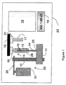
本発明は携帯型であり、使用が容易で、より正確な改善された粘度計、及び従来技術の粘度計よりも迅速な、液体のサンプルの粘度測定方法を提供する。図1を参照し、粘度計22は、参照番号20によって一般的に示される精密ポンプ、粘度測定が所望される液体のサンプルを供給するための液体容器14、通過液型粘度センサ15、コントローラ18、及びディスプレイ19を含む。
The present invention provides an improved viscometer that is portable, easy to use, more accurate, and a method for measuring viscosities of liquid samples that is faster than prior art viscometers. Referring to FIG. 1, a
ポンプ20は、ピペットバレル又は本体13と、プランジャ端部24がバレル13の端部から延びるピペットバレル13内に摺動可能に位置付けられたプランジャ12とを有する、図示され、ピペット14と称されるサンプル容器と連動して機能する。ピペット14は、ピペットが取り外され、試験される液体のサンプルで充填され、粘度計の取り付け機構内に再配置されることができ、又は取り外されて、試験される液体のサンプルを含む同様のピペットと交換されることができるように、取り付け機構28によって粘度計内に取り外し可能に位置付けられ、かつ保持されてもよい。ピペットは使い捨てにしてもよく、各液体のサンプルに対して新しく清浄なピペットが使用される。ポンプは、精密モーター23と、駆動機構26(例えば、歯車駆動装置又はベルト駆動装置)を通じてモーター23によって回転可能である主ネジ10と、ピペット14が粘度計内に位置付けられる際にピペットプランジャ端部24の端部25と接触する主ネジ10上に取り付けられたプッシュバック11とを含む。プッシュバック11は、モーター23によって主ネジ10の回転に反応し、主ネジ10に沿って横方向に移動する。
The
本発明で使用可能なピペット構成の例が、図3及び図4に図示される。ピペットプランジャ41は、ピペットバレル40内に密閉して、摺動自在に受容されたプランジャヘッド42を有し、端部45はピペットバレル40の端部から延びる。ピペットバレル及びピペットプランジャの両方が、射出成形によってプラスチックから作製することができる。プランジャは、バレル40の内側で前後に摺動することができる。サンプル液体でピペットを充填する際に、空気の取り込みを最小化するため、(図4に図示されるように)プランジャヘッド42の端部は、液体流バレル端部43に密接にフィットし、両者の間の空隙44を最小化する。図4に示される状態のピペットにおいて、ピペットの液体流端部43は、粘度が測定される液体内に挿入される。ユーザーは、ピペットバレル40から延びるプランジャ41の端部45を把持してプランジャをピペットバレルの端部43から後ろに引いて、バレル端部43の開口部を通じてサンプルをピペット内に引くことができる。図3は、ピペット内に引かれた液体のサンプルを収容するピペットバレル内の空間46を生成するために、バレル端部から後ろに引かれたプランジャ41を示す。ピペットプランジャ41をピペットバレル40内で後ろに引き続けると、サンプルは、増加する空間46内に引かれ続ける。所望の量のサンプルがピペットバレル内に引かれると、ユーザーは、プランジャ41を引くのをやめる。プランジャ41がバレル40の液体流端部43に向かって押されると、空間46内の流体は、バレル端部43の開口部を通じてバレル40から排出される。
Examples of pipette configurations that can be used with the present invention are illustrated in FIGS.
通過液型粘度センサ15は、液体入口コネクタ16及び液体出口コネクタ21を含む。図1に図示されるように、ピペットバレル13の端部から排出された液体は、液体入口コネクタ16を通じて、粘度センサ15へと連結される。液体排出管17は、液体出口コネクタ21を通じて、粘度センサ15の液体を出口から離れるように案内する。
The passing liquid
図2を参照し、通過液型粘度センサ15は、液体流路31を含み、流路入口35及び流路出口36が流路基材39内に形成される。流路31は、一面が開いた三面の流路31をもたらす流路基材39を備える矩形断面を有する。圧力センサ膜37及び圧力センサ基材30によって形成されるモノリシックセンサプレート38は、流路基材39と組み合わされて、流路31の開放面を閉じる。モノリシックセンサプレート38は、複数の別個の圧力センサを提供し、流路基材39に対して位置付けられ、流路入口35及び流路出口36から十分に離れるように離間されて、流路31に沿って少なくとも2つの別個の圧力センサを位置付け、それによって流路31を通じて十分に発達した液体流の圧力低下が圧力センサによって測定することができる。図2に図示される実施形態において、3つの別個の圧力センサが、流路31に沿って、モノリシックセンサプレート38によって提供される。別個の圧力センサはそれぞれ、圧力センサ膜37内の空洞33によって形成される。対応空洞33の上に延びる圧力センサ膜37の部分34は、対応空洞33上に延びる圧力センサ膜のこのような部分34に圧力が適用される際に、対応空洞33内へと屈曲する。対応空洞内への屈曲の度合いは、流路31内を流れる液体によって、対応空洞上の圧力センサ膜に適用される圧力に比例する。
Referring to FIG. 2, the passage liquid
空洞上の膜に適用される圧力の測定値を提供する、対応空洞内への膜の変位を検出するために、各空洞内に検出器が設けられる。1つのキャパシタ電極が空洞上の圧力センサ膜上に位置し、他のキャパシタ電極が空洞を被覆するセンサ基材30上に位置する、電気容量検出器など、様々な検出器が使用され得る。膜の変位が、キャパシタ電極が互いに近づくように動かし、電気容量を変化させ、それが圧力の測定をもたらす。液体流路31に沿った圧力センサ膜37の表面は実質的に平滑な連続的な表面であり、個別の圧力センサが表面に挿入されて不規則性及び不連続性を形成することがないことに留意する。この平滑な流路表面は、正確な圧力測定を得るために重要である。圧力センサの更なる詳細な説明、及び圧力センサ構成及び通過液型粘度センサのバリエーション及び異なる実施形態は、本発明者の米国特許第6,892,583号及び同第7,290,441号に提供されており、これらは本明細書の一部を構成するものとして援用する。液体流路入口35の周囲で流路基材39に取り付けられた液体入口コネクタ16は、加圧されたサンプル液体源(ここでは、ピペット14から排出された液体)との接続を提供し、液体流路出口36の周囲で流路基材39に取り付けられた液体出口コネクタ21は、サンプル液体排出管又は保持リザーバへの接続を提供する。
A detector is provided in each cavity to detect displacement of the film into the corresponding cavity that provides a measurement of the pressure applied to the film on the cavity. Various detectors can be used, such as a capacitance detector, where one capacitor electrode is located on the pressure sensor membrane above the cavity and the other capacitor electrode is located on the
コントローラ18は、粘度計及び周辺構成要素の動作を制御し、計算を実行し、測定された粘度及び粘度計の状態など他の情報を表示することができるディスプレイ19を制御し、並びに他のコンピュータなど他の装置と通信し情報伝達するための、1つ以上のマイクロコントローラ又はマイクロプロセッサ、並びに他の電気及び電子構成要素を含む。通信はRS232又はUSBポートなどのポートを介してもよく、又はワイヤレス若しくは他の通信手段を介してもよい。コントローラ18は一般的に、キーボード、タッチボタンパッド若しくはキーパッド、外部コンピュータ、又は他のデータ入力手段、例えばボタン、マウス、若しくディスプレイ19のタッチスクリーンなどのインターフェース手段を含み、これによりユーザーは、制御及び他の命令、並びに情報をコントローラに入力することができる。
The
液体のサンプルの粘度を測定するため、粘度が測定される液体のサンプルが、液体サンプルを保持するピペット中に確保される。ピペット内の液体のサンプルは、粘度計のユーザーによって、液体源からピペットへと引かれてもよく、ないしは別の方法でピペット内へと粘度計のユーザーに供給されてもよい。図1に図示されるように、ピペット14は、粘度計22内に取り付けられ、取り付け機構28によって粘度計内で適所に保持される。コントローラはその後、粘度測定を行うために、粘度計を制御するために起動される。コントローラは、モーター23を動作させ、プッシュバック11を、ピペットプランジャの端部25に対し、適所に前進させる(図1に図示される)。あるいは、プッシュバック11は、コントローラの起動の前にピペットが粘度計内に取り付けられる際に、ユーザーにより(例えば、手動で)位置付けられてもよい。
In order to measure the viscosity of the liquid sample, the liquid sample whose viscosity is to be measured is secured in the pipette holding the liquid sample. A sample of the liquid in the pipette may be drawn from the liquid source to the pipette by the viscometer user or otherwise supplied to the viscometer user into the pipette. As illustrated in FIG. 1, the
プッシュバック11がピペットプランジャの端部25に対して適所にある状態で、主ネジ10を回転させ、プッシュバック11及びピペットプランジャ12を所望の速度で前進させて、液体を既知の所望の流量でピペットから排出するように、コントローラはモーター23を制御する。プランジャが移動すると、液体がピペットから粘度センサ15内に圧入され、流路31を流れ、ここで十分に発達した液体流の圧力低下が、モノリシックな圧力センサ38の圧力センサによって測定される。流路31に沿った圧力センサの対応膜部分上の局所的な圧力が、センサ膜部分34を対応空洞33内へと屈曲させると、圧力が測定される。流路31に沿って測定される圧力低下(流路に沿った連続的な圧力センサの間で測定される圧力の差)は、特定の流量の液体の粘度に比例する。サンプル粘度が流量と共に変化する場合、流れを止めて、又は止めずに、順次異なる流量で液体を分配するように、制御が指示されてもよい。圧力値が得られ、粘度値が流量の関数として計算されるとき、非ニュートン性粘度に関して既知の方法で関係性が補正される。測定された粘度は、ディスプレイ19上に表示されてもよく、コントローラメモリ若しくは補助メモリに保存されてもよく、及び/又は遠隔メモリ若しくはコンピュータに送信されてもよい。
With the
最初に設定された流量(又は剪断速度)において、粘度センサ15の液体流路31内に液体が注入されると、粘度計は、液体流路31の内側の圧力を検出する。コントローラは、粘度測定の最高の精度、又は確実な精度のために、圧力レベルが最適であるかどうかを判定するようにプログラムすることができる。圧力レベルが低すぎる場合、コントローラは、次の流量値を決定及び設定し、流量を新しい設定値へと上げる。特定の粘度測定に関して最適な流量に到達するように、コントローラはこれを反復する。このように、既知の液体の粘度は、正確かつ自動的に測定され得る。
When a liquid is injected into the
液体のサンプルのための粘度測定値が得られたとき、プッシュバック11は、使用されたピペットが取り除かれ、試験のために内部に新しい液体のサンプルを有する新しいピペットが粘度計内に挿入されるようにするため、元の位置に戻るように操作される。試験される新しい液体のサンプルを有するピペットは、新しい使い捨てピペット、又は再度充填された使用済ピペットであってもよい。新しい粘度測定のため、コントローラは上記の粘度計を操作して、新しい液体のサンプルの粘度を測定する。この試験において、新しいサンプルからの液体は、粘度センサ15内の古いサンプルからの液体を置換する。このようにして、粘度センサの洗浄は不要となる。試験される2つの連続的な液体が適合しないか、又は不混和性である場合、粘度センサ15は、新しい液体を粘度センサ15に分配する前に、試験される両方の液体と適合する洗浄液で洗浄される必要がある。この洗浄は、2つの液体の試験の間に、洗浄液を含むピペットを粘度計に搭載し、粘度計を操作して、粘度センサ15を通じて洗浄液を圧入することによって行うことができる。
When a viscosity measurement for a liquid sample is obtained, the
粘度計22は、実際に携帯型となるように、充電式電池などの電池によって駆動されてもよく、又はそれが場所ごとに移動されたときに電源に接続することによって駆動されてもよい。
The
いくつかの例において、粘度が測定される液体の温度を制御することが望ましい場合がある。温度制御が望ましい場合、粘度計22、粘度センサ15、及び/又はピペット14内のサンプルは、ペルチェベースの温度制御装置、又は他の一般的に許容可能な温度制御手段によって、設定温度にて調整されてもよい。例えば、図1と似ている図5に図示されるように、ピペットが取り付け機構28内に取り付けられた際に、液体サンプル保持ピペット14、及び内部に収容される液体のサンプルを加熱又は冷却するように、温度制御装置50がピペット取り付け機構28内に配置されるか、又はこれと接触していてもよい。温度制御装置50がどのようにピペット取り付け機構28に取り付けられるかにより、ピペット取り付け機構もまた、設定温度まで加熱又は冷却することができる。ピペット内のサンプルが設定温度に達するまで、一定の時間が必要とされる場合がある。同様に、温度制御装置52は、粘度センサ15内に配置されるか、又はこれと接触していてもよく、粘度センサ15の流路31を形成する材料の温度を上昇又は低下させて、設定温度に維持する。これは、流路31を流れる材料を実質的に設定温度に維持する傾向がある。示されるように、温度制御装置は、ペルチェ装置又は他の既知の温度制御装置であってもよい。更に、粘度計の様々な位置でサンプル液体の温度を測定するために温度センサが位置付けられてもよい。例えば、先に参照した本発明者の特許に示されるように、流路31に沿ったセンサ膜37の1つ以上の位置で、温度センサが含まれ得る。上記のように、粘度計22の別個の構成要素の温度を別個に制御するのではなく、粘度計22又は温度制御されるその部分が、ハウジング内に取り付けられてよく、ここでハウジング内の温度、及び、したがってハウジング内の粘度計全体又はその部分の温度が一緒に温度制御される。
In some instances, it may be desirable to control the temperature of the liquid whose viscosity is measured. If temperature control is desired, the sample in the
先に参照した本発明者の特許に示されるように、記載される通過液型粘度センサは、非常に小さく、一般的に、半導体材料、又は微細製造プロセスで使用される他の材料により構成される。例えば、圧力センサ膜は、シリコンウエハーの一部であってもよく、一方で圧力センサ基材及び流路基材は、ボロシリケートガラスウエハーの部分であってもよい。流路は典型的には、約10マイクロメートルの幅、及び約1マイクロメートルの深さほどの小ささであり得、長さは約100マイクロメートルほどの短さである。したがって、通過液型粘度センサは非常に小さく、小さなサンプル寸法が粘度を決定するために使用することができる。通過液型粘度センサの、この小さな寸法、及び粘度試験に必要とされるサンプルの少ない量は、ピペット及びポンプなどの他の粘度計構成要素もまた、比較的小さく作製することができ、よって粘度計はまた比較的小さい携帯型ユニットとして容易に作製することができるということを意味する。 As shown in the above referenced inventor's patent, the described liquid-pass viscosity sensor is very small and is generally composed of semiconductor materials or other materials used in microfabrication processes. The For example, the pressure sensor membrane may be part of a silicon wafer, while the pressure sensor substrate and flow path substrate may be part of a borosilicate glass wafer. The flow path may typically be as small as about 10 micrometers wide and as deep as about 1 micrometer, with a length as short as about 100 micrometers. Thus, the passing liquid viscosity sensor is very small and a small sample size can be used to determine the viscosity. This small size of the pass-through viscosity sensor and the small amount of sample required for the viscosity test allows other viscometer components such as pipettes and pumps to also be made relatively small, thus the viscosity. The meter also means that it can be easily made as a relatively small portable unit.
携帯型粘度計を作製するのではなく、同じ粘度計が使用されて固定型粘度計を提供してもよく、固定型粘度計では、試験される液体のサンプルが異なるピペットの異なる位置から回収され、その後、粘度計に移送されて、粘度計の位置で試験され得る。 Rather than making a portable viscometer, the same viscometer may be used to provide a fixed viscometer, where samples of the liquid to be tested are collected from different locations on different pipettes. Can then be transferred to a viscometer and tested at the viscometer position.
必要に応じて、頻繁に測定されるか又は測定され得る液体に関して、公表されている、ないしは別の方法で既知である粘度値のデータベースが、粘度計コントローラのメモリ内に保存されてもよい。このような利用可能なデータベースにより、ユーザーは選択された液体に関するデータベースから既知の粘度値を容易に表示し、これを、既知の液体とみなされるサンプル液体に関して測定された粘度値と比較することができる。公表されている値と測定値との間の不一致は、試験液がそうであると思われた液体ではない可能性があることを示すか、又は粘度計に問題があり粘度計が点検され得ることを示し得る。加えて、様々な理由により、ユーザーは、その時に試験されている液体以外の特定の液体の既知の値にときおりアクセスすることが有利であり得る。更に粘度計は、測定された粘度値の履歴を適切に識別しながら保存してもよく、またこれは、粘度計のユーザーにより様々な目的のために使用することができる。例えば、測定された粘度値のこのような履歴により、ユーザーは、製造プロセスにおいて使用される液体成分の粘度を、異なる時点において比較し、その液体成分が液体成分に必要とされる規格の範囲内にあることを確認することができるか、又はその成分の粘度値を測定して、これを製造された製品の特定の所望の属性と相関させることができる。 If necessary, a database of viscosity values that are published or otherwise known for frequently measured or measurable liquids may be stored in the memory of the viscometer controller. With such an available database, the user can easily display a known viscosity value from the database for the selected liquid and compare this with the measured viscosity value for the sample liquid that is considered a known liquid. it can. A discrepancy between the published value and the measured value indicates that the test solution may not be the liquid that it seems to be, or there is a problem with the viscometer and the viscometer can be checked You can show that. In addition, for various reasons, it may be advantageous for the user to occasionally access a known value of a particular liquid other than the liquid being tested. In addition, the viscometer may store a history of the measured viscosity values with proper identification and can be used for various purposes by the viscometer user. For example, such a history of measured viscosity values allows users to compare the viscosity of a liquid component used in a manufacturing process at different points in time, and that the liquid component is within the specifications required for the liquid component. Or the viscosity value of the component can be measured and correlated with a particular desired attribute of the manufactured product.
本発明のポンプの例示される実施形態は、プランジャをピペット内に移動させるために、モーター、主ネジ、及びプッシュバックを含むものとして示され、記載されているが、プランジャをピペット内に移動させるための、又はサンプル容器からのサンプル液体の正確な排出をもたらすための他の様々な手段が使用されてもよい。 Although the illustrated embodiment of the pump of the present invention is shown and described as including a motor, a main screw, and a pushback to move the plunger into the pipette, the plunger is moved into the pipette. Various other means may be used for or to provide accurate drainage of the sample liquid from the sample container.
本発明は本明細書において、実際に本発明を実施するための最良の形態として、現在想到され得るその実施形態を参照として例示及び記載されているが、本発明に開示される発明の概念から逸脱することなく、本発明を異なる実施形態に適用するために様々な変更がなされ得ることが理解される。
Although the present invention has been illustrated and described herein with reference to the embodiments that can be conceived as the best mode for actually carrying out the present invention, the concept of the invention disclosed in the present invention will be described. It will be understood that various modifications can be made to apply the invention to different embodiments without departing.
Claims (28)
矩形の液体流路、前記矩形の液体流路に連結された液体入口コネクタ及び前記流路を通じて流れる十分に発達した液体流の圧力低下を測定する、前記流路に沿って位置付けられた少なくとも2つの圧力センサを有する、粘度センサと、
分配ポンプ機構であって、粘度の測定が所望される液体を収容するように適合された容積移送式ピペットに連結するように適合され、これによって、前記分配ポンプ機構の動作が、容積移送式ピペットと協働して、既知の流量で前記液体を前記容積移送式ピペットから分配するものであり、且つ、前記液体入口コネクタを通じて前記容積移送式ピペットが直接連結するように適合された前記粘度センサに連結するように適合され、これによって、粘度の測定が所望される前記液体を、前記容積移送式ピペットから分配した際に、既知の流量で前記液体入口コネクタを通じて前記粘度センサ内へと圧入し、十分に発達した液体流が前記粘度センサの流路を通じて流れるものである、分配ポンプ機構と、
前記粘度計の動作を制御し、センサデータを処理するコントローラとを備える、携帯型粘度計。 A portable viscometer ,
Liquid flow path rectangle, measuring the pressure drop of the fully developed flow of liquid flowing through the liquid inlet connector and the channel connected to the liquid flow path of the rectangular, at least positioned along the flow path 2 A viscosity sensor having two pressure sensors;
A dispensing pump mechanism adapted to be coupled to a positive displacement pipette adapted to contain a liquid whose viscosity is desired to be measured, whereby the operation of the dispensing pump mechanism is controlled by the positive displacement pipette Cooperating with the viscosity sensor to dispense the liquid from the positive displacement pipette at a known flow rate and adapted to connect directly to the positive displacement pipette through the liquid inlet connector. adapted to be connected, thereby press-fitting, the liquid viscosity measurements are desired, upon distribution the positive displacement pipettes or al minute, into said viscosity sensor through said liquid inlet connector at a known flow rate A dispensing pump mechanism, wherein a fully developed liquid flow flows through the flow path of the viscosity sensor;
A portable viscometer comprising a controller for controlling the operation of the viscometer and processing sensor data.
3つの側壁、流路入口、及び流路出口を有して、内部に形成された少なくとも1つの流路を備える流路基材と、
実質的に平滑な検出面、及び内部の異なる位置において少なくとも2つの別個の圧力センサを有するモノリシックセンサプレートとを備え、
前記センサプレートの実質的に平滑な検出面が、前記少なくとも1つの流路の第4側壁となり、前記少なくとも1つの流路を通じて流れている液体の完全な収容を可能にするように、前記流路基材及び前記モノリシックセンサプレートが組み合わされ、前記液体が前記流路を流れる際に、前記少なくとも1つの流路内の前記液体の十分に発達した流れの圧力低下が測定されるように、前記モノリシックセンサプレートの前記少なくとも2つの別個の圧力センサの少なくとも2つが、前記流路入口及び前記流路出口から十分に離れて前記少なくとも1つの流路に沿って位置付けられる、請求項1乃至9のいずれか1項に記載の携帯型粘度計。 The viscosity sensor is
A flow path substrate having at least one flow path formed therein, having three side walls, a flow path inlet, and a flow path outlet;
A substantially smooth sensing surface and a monolithic sensor plate having at least two separate pressure sensors at different locations inside the
The flow path is such that a substantially smooth detection surface of the sensor plate becomes a fourth side wall of the at least one flow path and allows complete accommodation of the liquid flowing through the at least one flow path. The monolithic sensor plate is combined so that when the liquid flows through the flow path, a pressure drop of a fully developed flow of the liquid in the at least one flow path is measured. wherein at least 2 of said at least two separate pressure sensors of the sensor plate is positioned along said at least one channel well away from the flow channel inlet and said channel outlet, any one of claims 1 to 9 The portable viscometer according to item 1.
求項1乃至12のいずれか1項に記載の携帯型粘度計。 The portable viscometer according to any one of claims 1 to 12 , wherein the portable viscometer stores a database of known viscosity values for a plurality of liquids.
分配ポンプ機構と、
矩形の液体流路、及び前記流路を通じて流れる十分に発達した液体流の圧力低下を測定する、前記流路に沿って位置付けられた少なくとも2つの圧力センサを有する、粘度センサと、
粘度の測定が所望される液体を収容するように適合された容積移送式ピペットを、取り外し可能に取り付けるように適合された取り付け機構であって、前記取り付け機構は、前記分配ポンプ機構と協働する位置に、前記容積移送式ピペットを取り付けるよう適合され、これによって前記分配ポンプ機構の動作が前記容積移送式ピペットから前記液体を既知の流量で分配し、並びに、前記粘度センサと協働するように適合され、これによって粘度の測定が所望される前記液体が、前記容積移送式ピペットから分配した際に既知の流量で前記粘度センサ内に圧入され、十分に発達した液体流が前記粘度センサの流路を通じて流れる、取り付け機構と、
前記粘度計の動作を制御し、センサデータを処理するコントローラとを備える、携帯型粘度計。 A portable viscometer,
A distribution pump mechanism;
A viscosity sensor having a rectangular liquid flow path and at least two pressure sensors positioned along the flow path for measuring a pressure drop of a fully developed liquid flow flowing through the flow path;
An attachment mechanism adapted to removably attach a positive displacement pipette adapted to contain a liquid whose viscosity is desired to be measured, the attachment mechanism cooperating with the dispensing pump mechanism in position, is adapted to fit the said positive displacement pipette, whereby partitioned known flow rate the liquid behavior from the positive displacement pipettes of the dispensing pump mechanism, and cooperates with the viscosity sensor is adapted to the liquid whereby the measurement of the viscosity is desired it is, the press-fitted into the positive displacement pipettes or al fraction distribution was in the viscosity sensor at a known flow rate when, fully developed liquid flow the An attachment mechanism that flows through the flow path of the viscosity sensor ;
A portable viscometer comprising a controller for controlling the operation of the viscometer and processing sensor data.
分配ポンプ機構と、
矩形の液体流路、及び前記流路を通じて流れる十分に発達した液体流の圧力低下を測定する、前記流路に沿って位置付けられた少なくとも2つの圧力センサを有する、粘度センサと、
粘度の測定が所望されるサンプル液を収容するように適合された容積移送式ピペットを、取り外し可能に取り付けるように適合された取り付け機構であって、前記取り付け機構は、前記分配ポンプ機構と協働する位置に、前記容積移送式ピペットを取り付けるよう適合され、これによって前記分配ポンプ機構の動作が前記容積移送式ピペットから前記サンプル液を既知の流量で分配し、並びに、前記粘度センサと協働するように適合され、これによって粘度の測定が所望される前記サンプル液が、前記容積移送式ピペットから分配した際に、前記粘度センサ内に圧入され、十分に発達した液体流が前記粘度センサの流路を通じて流れる、取り付け機構と、
前記粘度計の動作を制御し、センサデータを処理するコントローラとを備える、携帯型粘度計を入手する工程と、
粘度の測定が所望される液体を収容する容積移送式ピペットを入手する工程と、
粘度の測定が所望される前記液体を収容する前記容積移送式ピペットを前記取り付け機構内に配置する工程と、
前記携帯型粘度計を操作して、前記容積移送式ピペット内に収容された粘度の測定が所望される前記液体の粘度の測定値を、既知の流量で前記携帯型粘度計を通じて前記液体が流れる間、得る工程とを含む、方法。 A method for obtaining a viscosity measurement of a liquid for which viscosity measurement is desired,
A distribution pump mechanism;
A viscosity sensor having a rectangular liquid flow path and at least two pressure sensors positioned along the flow path for measuring a pressure drop of a fully developed liquid flow flowing through the flow path;
An attachment mechanism adapted to removably attach a positive displacement pipette adapted to contain a sample liquid whose viscosity is desired to be measured , the attachment mechanism cooperating with the dispensing pump mechanism a position, the is adapted fit the volume transfer pipette, thereby distributing the sample liquid operation of the dispensing pump mechanism from said positive displacement pipette with a known flow rate, as well as the viscosity sensor and cooperative is adapted to work, the sample liquid thereby measuring the viscosity is desired is, when dispensed from said positive displacement pipette, the press-fitted into the viscosity sensor, the sufficiently developed liquid flow viscosity sensor An attachment mechanism that flows through the flow path of
It controls the operation of the pre Kineba meter, and a controller for processing the sensor data, the step of obtaining a portable viscometer,
A step of obtaining a positive displacement pipette for accommodating a liquid to measurement of viscosity is desired,
Placing said positive displacement pipette for accommodating the liquid to measurement of viscosity is desired in the mounting mechanism,
By operating the portable viscometer, the liquid flows through the portable viscometer at a known flow rate through the measured value of the viscosity of the liquid desired to be measured for the viscosity contained in the positive displacement pipette. And obtaining a process.
請求項20乃至26の何れか1項に記載の携帯型粘度計を入手する工程と、
粘度の測定が所望される液体を収容する容積移送式ピペットを入手する工程と、
粘度の測定が所望される前記液体を収容する前記容積移送式ピペットを前記取り付け機構内に配置する工程と、
前記携帯型粘度計を操作して、前記容積移送式ピペット内に収容された粘度の測定が所望される前記液体の粘度の測定値を、既知の流量で前記携帯型粘度計を通じて前記液体が流れる間、得る工程とを含む、方法。 A method for obtaining a viscosity measurement of a liquid for which viscosity measurement is desired,
Obtaining a portable viscometer according to any one of claims 20 to 26;
Obtaining a positive displacement pipette containing a liquid whose viscosity is desired to be measured;
Placing the positive displacement pipette containing the liquid whose viscosity is desired to be measured in the attachment mechanism;
By operating the portable viscometer, the liquid flows through the portable viscometer at a known flow rate through the measured value of the viscosity of the liquid desired to be measured for the viscosity contained in the positive displacement pipette. And obtaining a process.
Applications Claiming Priority (3)
| Application Number | Priority Date | Filing Date | Title |
|---|---|---|---|
| US32788910P | 2010-04-26 | 2010-04-26 | |
| US61/327,889 | 2010-04-26 | ||
| PCT/US2011/034002 WO2011139719A2 (en) | 2010-04-26 | 2011-04-26 | Portable viscometer |
Publications (3)
| Publication Number | Publication Date |
|---|---|
| JP2013525799A JP2013525799A (en) | 2013-06-20 |
| JP2013525799A5 JP2013525799A5 (en) | 2014-05-15 |
| JP6042803B2 true JP6042803B2 (en) | 2016-12-14 |
Family
ID=44904345
Family Applications (1)
| Application Number | Title | Priority Date | Filing Date |
|---|---|---|---|
| JP2013508172A Active JP6042803B2 (en) | 2010-04-26 | 2011-04-26 | Portable viscometer |
Country Status (5)
| Country | Link |
|---|---|
| US (1) | US10451532B2 (en) |
| EP (1) | EP2564181B1 (en) |
| JP (1) | JP6042803B2 (en) |
| CN (2) | CN103080724B (en) |
| WO (1) | WO2011139719A2 (en) |
Families Citing this family (17)
| Publication number | Priority date | Publication date | Assignee | Title |
|---|---|---|---|---|
| US9389159B2 (en) * | 2008-08-01 | 2016-07-12 | Malvern Instruments Ltd. | Expert-system-based rheology |
| US10451532B2 (en) | 2010-04-26 | 2019-10-22 | Rheosense, Inc. | Portable viscometer |
| US20150168284A1 (en) * | 2012-08-20 | 2015-06-18 | The United States Of America, As Represented By The Secretary, Dept. Of Health And Human Services | Capillary viscometer and multiscale pressure differential measuring device |
| USD786279S1 (en) | 2013-03-15 | 2017-05-09 | Brookfield Engineering Laboratories, Inc. | Display screen with graphical user interface for a viscometer or rheometer |
| WO2014144668A2 (en) * | 2013-03-15 | 2014-09-18 | Brookfield Engineering Laboratories, Inc. | Measurement instrument having touchscreen user interface and method for measuring viscosity |
| US10209171B2 (en) | 2013-12-09 | 2019-02-19 | Texas Tech University System | Smart phone based multiplexed viscometer for high throughput analysis of fluids |
| EP3155399B1 (en) * | 2014-04-11 | 2020-12-02 | Rheosense Inc. | Viscometer and methods for using the same |
| CN105675445B (en) * | 2016-03-25 | 2018-06-05 | 中国石油大学(华东) | Supercritical carbon dioxide capillary viscometer and application method under a kind of high temperature and pressure |
| AT518911B1 (en) * | 2016-07-18 | 2022-01-15 | Erema Eng Recycling Maschinen & Anlagen Gmbh | Process and device for online determination of the viscosity of a polymer |
| EP3526580B1 (en) * | 2016-10-11 | 2024-03-27 | Rheosense Inc. | Viscometer and methods for using the same |
| CN106525656B (en) * | 2016-11-30 | 2023-12-12 | 上海大学 | Portable viscosity detection device |
| US10144537B2 (en) | 2016-11-30 | 2018-12-04 | Mallinckrodt Nuclear Medicine Llc | Systems and methods for dispensing radioactive liquids |
| US11366046B2 (en) | 2017-02-10 | 2022-06-21 | Hewlett-Packard Development Company, L.P. | Determine viscosity of fluids using a capillary channel |
| WO2019060716A1 (en) * | 2017-09-25 | 2019-03-28 | Freenome Holdings, Inc. | Methods and systems for sample extraction |
| US10613010B2 (en) * | 2017-12-06 | 2020-04-07 | Ametek, Inc. | Intertial torque device for viscometer calibration and rheology measurements |
| US20210172848A1 (en) * | 2019-12-10 | 2021-06-10 | King Abdullah University Of Science And Technology | Viscosity sensor for real-time monitoring of tubular conduits and method |
| CN111307663A (en) * | 2020-03-02 | 2020-06-19 | 上海交通大学 | Gas viscosity measuring device |
Family Cites Families (91)
| Publication number | Priority date | Publication date | Assignee | Title |
|---|---|---|---|---|
| US3143393A (en) * | 1959-06-18 | 1964-08-04 | Luc Donald De Seguin Des Hons | Apparatus for automatically performing chemical operations and similar or related operations |
| US3266299A (en) * | 1965-06-14 | 1966-08-16 | Roy L Swank | Constant flow pressure filter apparatus |
| US3683678A (en) * | 1971-05-03 | 1972-08-15 | Du Pont | Method and apparatus for molecular weight measurement |
| DE2444148C3 (en) * | 1974-09-16 | 1981-09-17 | Dr. Karl Thomae Gmbh, 7950 Biberach | Capillary viscometer |
| US4122708A (en) | 1976-03-31 | 1978-10-31 | Simmonds Precision Products, Inc. | Capacitive proximity sensors |
| US4141252A (en) * | 1977-11-04 | 1979-02-27 | Lodge Arthur S | Flush pressure transducers for measuring pressures in a flowing fluid |
| FI57542C (en) | 1978-06-02 | 1980-09-10 | Suovaniemi Finnpipette | VOLUMREGLERBAR PIPETT |
| US4241602A (en) | 1979-04-20 | 1980-12-30 | Seismograph Service Corporation | Rheometer |
| US4916678A (en) | 1979-06-29 | 1990-04-10 | Phillips Petroleum Company | Viscometer |
| JPS56157839A (en) * | 1980-05-09 | 1981-12-05 | Japan Synthetic Rubber Co Ltd | Slit die type rheometer |
| JPS5745430A (en) | 1980-09-02 | 1982-03-15 | Japan Synthetic Rubber Co Ltd | Slit die rheometer |
| US4422210A (en) | 1980-11-12 | 1983-12-27 | Goteborgs Maskinkonsult Aktiebolag | Installation for internal cleaning of tubes |
| FI62470C (en) * | 1981-06-17 | 1983-01-10 | Labsystems Oy | pipette |
| JPS5888637A (en) | 1981-11-21 | 1983-05-26 | Japan Synthetic Rubber Co Ltd | Die rheometer |
| US4574622A (en) * | 1984-03-27 | 1986-03-11 | Union Carbide Corporation | Viscometer |
| GB2158252B (en) | 1984-04-12 | 1988-08-24 | John Parnaby | Pheometer |
| JPS61107251A (en) | 1984-10-31 | 1986-05-26 | Canon Inc | Electrophotographic sensitive body |
| JPS61190853A (en) | 1985-02-18 | 1986-08-25 | 松下電子工業株式会社 | Incandescent bulb |
| JPS61190853U (en) * | 1985-05-21 | 1986-11-27 | ||
| DE3635462A1 (en) | 1985-10-21 | 1987-04-23 | Sharp Kk | FIELD EFFECT PRESSURE SENSOR |
| AT396998B (en) | 1985-12-09 | 1994-01-25 | Ottosensors Corp | MEASURING DEVICES AND PIPE CONNECTION AND METHOD FOR PRODUCING A MEASURING DEVICE AND METHOD FOR CONNECTING TUBES TO A MEASURING DEVICE OR FOR THE PRODUCTION OF PIPE CONNECTIONS |
| KR900006574Y1 (en) | 1986-01-29 | 1990-07-26 | 가부시끼가이샤 마르콤 | Rotary viscometer |
| JPH0654287B2 (en) | 1986-02-21 | 1994-07-20 | 日本鋼管株式会社 | Non-newtonian measuring device in pipeline |
| US4920787A (en) | 1987-06-12 | 1990-05-01 | Dual Juerg | Viscometer |
| US4874500A (en) | 1987-07-15 | 1989-10-17 | Sri International | Microelectrochemical sensor and sensor array |
| US4793174A (en) * | 1987-10-05 | 1988-12-27 | E. I. Du Pont De Nemours And Company | Differential pressure capillary viscometer |
| US5029479A (en) | 1988-08-15 | 1991-07-09 | Imo Industries, Inc. | Differential pressure transducers |
| US5058435A (en) | 1989-06-22 | 1991-10-22 | Ic Sensors, Inc. | Single diaphragm transducer with multiple sensing elements |
| US5189777A (en) | 1990-12-07 | 1993-03-02 | Wisconsin Alumni Research Foundation | Method of producing micromachined differential pressure transducers |
| US5347851A (en) * | 1991-04-04 | 1994-09-20 | Dynisco, Inc. | Capillary rheometer plunger pressure transducer and measurement technique |
| JP2582003B2 (en) * | 1991-05-22 | 1997-02-19 | 本田技研工業株式会社 | Pressure source for pressure equipment |
| US5225959A (en) | 1991-10-15 | 1993-07-06 | Xerox Corporation | Capacitive tactile sensor array and method for sensing pressure with the array |
| JP3203560B2 (en) | 1991-12-13 | 2001-08-27 | ハネウエル・インコーポレーテッド | Piezoresistive silicon pressure sensor design |
| US5317908A (en) | 1992-04-28 | 1994-06-07 | National Metal Refining Company, Inc. | High viscosity transducer for vibratory viscometer |
| US5486335A (en) | 1992-05-01 | 1996-01-23 | Trustees Of The University Of Pennsylvania | Analysis based on flow restriction |
| US5304487A (en) | 1992-05-01 | 1994-04-19 | Trustees Of The University Of Pennsylvania | Fluid handling in mesoscale analytical devices |
| JP3262373B2 (en) * | 1992-06-30 | 2002-03-04 | 株式会社東芝 | Flow resistance evaluation method and device |
| CA2074289C (en) | 1992-07-21 | 1999-09-14 | Claude Belleville | Fabry-perot optical sensing device for measuring a physical parameter |
| JPH06201420A (en) | 1992-12-28 | 1994-07-19 | Fujikura Ltd | Flow sensor and fabrication thereof |
| DE4330562A1 (en) * | 1993-09-09 | 1995-03-16 | Behringwerke Ag | Plastic pipette |
| US5388447A (en) * | 1993-11-26 | 1995-02-14 | Diagnetics, Inc. | Viscosity measurement apparatus |
| US5602339A (en) | 1994-03-24 | 1997-02-11 | Dynisco, Inc. | Injection molding machine pressure transducer with trapezoidal cavity |
| US5503003A (en) | 1994-12-14 | 1996-04-02 | Brookfield Engineering Laboratories, Inc. | Portable viscometer |
| CA2145599C (en) | 1995-03-27 | 2001-12-04 | David Wesley Forbes | Method of continuously testing the accuracy of results obtained from an automatic viscometer |
| US5663503A (en) | 1995-09-08 | 1997-09-02 | Cosense, Inc. | Invasive and non-invasive ultrasonic sensor with continuous and demand self-test |
| CA2185292A1 (en) * | 1995-09-15 | 1997-03-16 | James C. Smith | Positive displacement liquid drawing and dispensing apparatus and method |
| DE19614458C2 (en) | 1996-04-12 | 1998-10-29 | Grundfos As | Pressure or differential pressure sensor and method for its production |
| KR100432068B1 (en) | 1996-04-13 | 2004-09-08 | 로베르트 보쉬 게엠베하 | Pressure sensor |
| US5877409A (en) * | 1997-06-06 | 1999-03-02 | Mobil Oil Corporation | Method and system for determining viscosity index |
| EP0884578A3 (en) * | 1997-06-09 | 1999-09-22 | Dickey-John Corporation | Portable viscometer with crystal resonator-type sensor |
| US5983727A (en) | 1997-08-19 | 1999-11-16 | Pressure Profile Systems | System generating a pressure profile across a pressure sensitive membrane |
| DE19750131C2 (en) | 1997-11-13 | 2002-06-13 | Infineon Technologies Ag | Micromechanical differential pressure sensor device |
| JP3873084B2 (en) | 1997-12-29 | 2007-01-24 | 財団法人くまもとテクノ産業財団 | Kinematic viscometer |
| US6237398B1 (en) | 1997-12-30 | 2001-05-29 | Remon Medical Technologies, Ltd. | System and method for monitoring pressure, flow and constriction parameters of plumbing and blood vessels |
| JPH11248715A (en) * | 1998-03-06 | 1999-09-17 | Matsushita Electric Ind Co Ltd | Dispensing head and chip |
| US6010461A (en) | 1998-09-01 | 2000-01-04 | Sitek, Inc. | Monolithic silicon intra-ocular pressure sensor and method therefor |
| US6078706A (en) | 1998-09-22 | 2000-06-20 | The United States Of America As Represented By The Secretary Of The Navy | Quasi-static fiber pressure sensor |
| US6032689A (en) | 1998-10-30 | 2000-03-07 | Industrial Technology Research Institute | Integrated flow controller module |
| US6216528B1 (en) * | 1998-12-15 | 2001-04-17 | Caterpillar Inc. | Method and apparatus for determining a viscosity of an actuating fluid |
| US6338284B1 (en) | 1999-02-12 | 2002-01-15 | Integrated Sensing Systems (Issys) Inc. | Electrical feedthrough structures for micromachined devices and methods of fabricating the same |
| DE19911441B4 (en) | 1999-03-04 | 2011-04-07 | Anton Paar Gmbh | Rheometer or rotational viscometer |
| AT409304B (en) | 1999-09-24 | 2002-07-25 | Anton Paar Gmbh | Rotational |
| US6575019B1 (en) | 2000-01-14 | 2003-06-10 | Chandler Engineering Company Llc | Reciprocating drive/pump system and reciprocating capillary viscometer utilizing same |
| GB0002192D0 (en) | 2000-01-31 | 2000-03-22 | Borealis Polymers Oy | Rheometry |
| US6681616B2 (en) * | 2000-02-23 | 2004-01-27 | Caliper Technologies Corp. | Microfluidic viscometer |
| CA2399199A1 (en) * | 2000-02-23 | 2001-08-30 | Ring-Ling Chien | Multi-reservoir pressure control system |
| US6553812B2 (en) | 2000-05-02 | 2003-04-29 | Kavlico Corporation | Combined oil quality and viscosity sensing system |
| US6393898B1 (en) | 2000-05-25 | 2002-05-28 | Symyx Technologies, Inc. | High throughput viscometer and method of using same |
| WO2002072264A1 (en) | 2001-03-09 | 2002-09-19 | Biomicro Systems, Inc. | Method and system for microfluidic interfacing to arrays |
| US7290441B2 (en) | 2001-10-31 | 2007-11-06 | Rheosense, Inc. | Micro slit viscometer with monolithically integrated pressure sensors |
| JP4272525B2 (en) | 2001-10-31 | 2009-06-03 | レオセンス,インコーポレイテッド | Pressure detector for rheometer |
| US7770436B2 (en) | 2001-10-31 | 2010-08-10 | Rheosense, Inc. | Micro rheometer for measuring flow viscosity and elasticity for micron sample volumes |
| DE10215946B4 (en) * | 2002-04-11 | 2004-02-26 | Krauss-Maffei Kunststofftechnik Gmbh | Rheological measuring device for an injection molding machine |
| GB0217494D0 (en) | 2002-07-29 | 2002-09-04 | Boc Group Plc | Conditioning monitoring of pumps and pump systems |
| CN101124467B (en) * | 2004-03-11 | 2011-04-20 | 电流感应器公司 | Micro slit viscometer with monolithically integrated pressure sensors |
| JP4602162B2 (en) * | 2004-06-15 | 2010-12-22 | セイコーインスツル株式会社 | Microchip system |
| US9477233B2 (en) | 2004-07-02 | 2016-10-25 | The University Of Chicago | Microfluidic system with a plurality of sequential T-junctions for performing reactions in microdroplets |
| ATE473442T1 (en) * | 2004-07-23 | 2010-07-15 | Biosystem Dev Llc | DEVICE FOR AN IMMUNOASSAY AND METHOD FOR USE THEREOF |
| WO2006039513A1 (en) | 2004-10-01 | 2006-04-13 | Halliburton Energy Services, Inc. | Method and apparatus for acquiring physical properties of fluid samples |
| JP4657803B2 (en) * | 2005-05-19 | 2011-03-23 | 富士フイルム株式会社 | Liquid feeding system, liquid feeding method and flow path unit. |
| US7730769B1 (en) | 2006-05-24 | 2010-06-08 | Kwon Kyung C | Capillary viscometers for use with Newtonian and non-Newtonian fluids |
| US7558255B2 (en) * | 2006-07-13 | 2009-07-07 | Alcatel-Lucent Usa Inc. | Method of switching modes of uplink transmission in a wireless communication system |
| US20080125700A1 (en) * | 2006-11-29 | 2008-05-29 | Moberg Sheldon B | Methods and apparatuses for detecting medical device acceleration, temperature, and humidity conditions |
| US20090004063A1 (en) | 2007-06-29 | 2009-01-01 | Symyx Technologies, Inc. | Apparatus and method for actuating a syringe |
| FR2927999B1 (en) * | 2008-02-21 | 2010-09-17 | Gilson Sas | VISCOSIMETER COMPRISING A PIPETAGE SYSTEM, WITH IMPROVED PRECISION AND SIMPLIFIED DESIGN |
| US8230723B2 (en) | 2008-09-19 | 2012-07-31 | Chandler Instruments Company, LLC | High pressure high temperature viscometer |
| JP4706883B2 (en) | 2009-03-17 | 2011-06-22 | セイコーエプソン株式会社 | Biological sample quantification method |
| WO2010111366A1 (en) | 2009-03-24 | 2010-09-30 | Norcross Corporation | Mixers for a viscometer and methods and computer-readable media for using the same |
| US10451532B2 (en) | 2010-04-26 | 2019-10-22 | Rheosense, Inc. | Portable viscometer |
| US20150168284A1 (en) | 2012-08-20 | 2015-06-18 | The United States Of America, As Represented By The Secretary, Dept. Of Health And Human Services | Capillary viscometer and multiscale pressure differential measuring device |
| EP3155399B1 (en) | 2014-04-11 | 2020-12-02 | Rheosense Inc. | Viscometer and methods for using the same |
-
2011
- 2011-04-26 US US13/094,710 patent/US10451532B2/en active Active
- 2011-04-26 WO PCT/US2011/034002 patent/WO2011139719A2/en active Application Filing
- 2011-04-26 EP EP11777928.0A patent/EP2564181B1/en active Active
- 2011-04-26 CN CN201180031161.1A patent/CN103080724B/en active Active
- 2011-04-26 JP JP2013508172A patent/JP6042803B2/en active Active
- 2011-04-26 CN CN201610164123.8A patent/CN105784547B/en active Active
Also Published As
| Publication number | Publication date |
|---|---|
| WO2011139719A2 (en) | 2011-11-10 |
| CN103080724A (en) | 2013-05-01 |
| US20120096929A1 (en) | 2012-04-26 |
| EP2564181A4 (en) | 2017-11-15 |
| JP2013525799A (en) | 2013-06-20 |
| CN103080724B (en) | 2016-04-13 |
| WO2011139719A8 (en) | 2012-04-05 |
| EP2564181B1 (en) | 2021-08-25 |
| CN105784547B (en) | 2019-11-05 |
| CN105784547A (en) | 2016-07-20 |
| EP2564181A2 (en) | 2013-03-06 |
| WO2011139719A3 (en) | 2012-05-31 |
| US10451532B2 (en) | 2019-10-22 |
Similar Documents
| Publication | Publication Date | Title |
|---|---|---|
| JP6042803B2 (en) | Portable viscometer | |
| US11624692B2 (en) | Viscometer and methods for using the same | |
| JP2013525799A5 (en) | ||
| CN101334420B (en) | Chemical analysis apparatus and analysis device | |
| US20060179923A1 (en) | Nanoliter viscometer for analyzing blood plasma and other liquid samples | |
| JP2011512538A (en) | Pipette system and method for measuring viscosity | |
| CN1920526B (en) | Method and equipment for measuring fluid viscosity of capillary pipeline | |
| US7681437B2 (en) | Device for determining the viscosity of fluids | |
| EP4337285A1 (en) | Viscometer with reduced dead-volume and high dynamic range | |
| CN109759160B (en) | A kind of biochip reagent quantitative Adding Way and system | |
| WO2017194983A1 (en) | Device and method to sample liquids with high-precision in an automated sample analyzer | |
| EP3526580B1 (en) | Viscometer and methods for using the same | |
| US10900983B2 (en) | Method for operating a dosing device |
Legal Events
| Date | Code | Title | Description |
|---|---|---|---|
| A521 | Request for written amendment filed |
Free format text: JAPANESE INTERMEDIATE CODE: A523 Effective date: 20140326 |
|
| A621 | Written request for application examination |
Free format text: JAPANESE INTERMEDIATE CODE: A621 Effective date: 20140326 |
|
| A977 | Report on retrieval |
Free format text: JAPANESE INTERMEDIATE CODE: A971007 Effective date: 20150309 |
|
| A131 | Notification of reasons for refusal |
Free format text: JAPANESE INTERMEDIATE CODE: A131 Effective date: 20150407 |
|
| A601 | Written request for extension of time |
Free format text: JAPANESE INTERMEDIATE CODE: A601 Effective date: 20150706 |
|
| A601 | Written request for extension of time |
Free format text: JAPANESE INTERMEDIATE CODE: A601 Effective date: 20150806 |
|
| A521 | Request for written amendment filed |
Free format text: JAPANESE INTERMEDIATE CODE: A523 Effective date: 20150903 |
|
| RD02 | Notification of acceptance of power of attorney |
Free format text: JAPANESE INTERMEDIATE CODE: A7422 Effective date: 20150903 |
|
| A521 | Request for written amendment filed |
Free format text: JAPANESE INTERMEDIATE CODE: A821 Effective date: 20150904 |
|
| A131 | Notification of reasons for refusal |
Free format text: JAPANESE INTERMEDIATE CODE: A131 Effective date: 20160301 |
|
| A521 | Request for written amendment filed |
Free format text: JAPANESE INTERMEDIATE CODE: A523 Effective date: 20160530 |
|
| TRDD | Decision of grant or rejection written | ||
| A01 | Written decision to grant a patent or to grant a registration (utility model) |
Free format text: JAPANESE INTERMEDIATE CODE: A01 Effective date: 20161025 |
|
| A61 | First payment of annual fees (during grant procedure) |
Free format text: JAPANESE INTERMEDIATE CODE: A61 Effective date: 20161110 |
|
| R150 | Certificate of patent or registration of utility model |
Ref document number: 6042803 Country of ref document: JP Free format text: JAPANESE INTERMEDIATE CODE: R150 |
|
| R250 | Receipt of annual fees |
Free format text: JAPANESE INTERMEDIATE CODE: R250 |
|
| R250 | Receipt of annual fees |
Free format text: JAPANESE INTERMEDIATE CODE: R250 |
|
| R250 | Receipt of annual fees |
Free format text: JAPANESE INTERMEDIATE CODE: R250 |
|
| R250 | Receipt of annual fees |
Free format text: JAPANESE INTERMEDIATE CODE: R250 |
|
| R250 | Receipt of annual fees |
Free format text: JAPANESE INTERMEDIATE CODE: R250 |