JP6039452B2 - Rotating electric machine stator - Google Patents
Rotating electric machine stator Download PDFInfo
- Publication number
- JP6039452B2 JP6039452B2 JP2013026572A JP2013026572A JP6039452B2 JP 6039452 B2 JP6039452 B2 JP 6039452B2 JP 2013026572 A JP2013026572 A JP 2013026572A JP 2013026572 A JP2013026572 A JP 2013026572A JP 6039452 B2 JP6039452 B2 JP 6039452B2
- Authority
- JP
- Japan
- Prior art keywords
- wedge
- slot
- stator
- recess
- groove
- Prior art date
- Legal status (The legal status is an assumption and is not a legal conclusion. Google has not performed a legal analysis and makes no representation as to the accuracy of the status listed.)
- Expired - Fee Related
Links
Images


Description
本発明の実施形態は、鉄心に設けたコイル用スロット部の楔溝への、コイル固定用の楔の取り付け構造を改良した回転電機の固定子に関する。 Embodiments of the present invention relate to a stator for a rotating electrical machine having an improved structure for attaching a coil fixing wedge to a wedge groove of a coil slot provided in an iron core.
電動機や発電機などの回転電機の固定子は、円筒状を成す固定子鉄心を有する。この固定子鉄心は、珪素鋼板を積層し、所定の厚み毎にスペーサを介在させて径方向の通風ダクトを形成しながら、全体として円筒状に形成される。また、この固定子鉄心の内周面(回転子外周との対向面)には、軸方向に沿うコイル用のスロットが複数本、全周にわたって所定間隔で形成される。このスロットは、固定子コイルを収容するもので、固定子鉄心の内周面への開溝部はコイル固定用の楔により覆われている。すなわち、スロットの開溝部の両内側壁には、このスロットの長さ方向に沿って楔溝が形成されており、コイル固定用の楔は、その両側部が楔溝内に係合した状態でスロットの開溝部を覆う。この楔は、スロットの開溝部を覆った状態で、その裏面によりスペーサを介してスロット内に収容されたコイルを固定する。 A stator of a rotating electric machine such as an electric motor or a generator has a cylindrical stator core. The stator core is formed in a cylindrical shape as a whole while laminating silicon steel plates and interposing a spacer for each predetermined thickness to form a radial ventilation duct. In addition, a plurality of coil slots along the axial direction are formed on the inner peripheral surface of the stator core (the surface facing the outer periphery of the rotor) at predetermined intervals along the entire circumference. This slot accommodates the stator coil, and the groove portion on the inner peripheral surface of the stator core is covered with a coil fixing wedge. That is, a wedge groove is formed along the length direction of the slot on both inner side walls of the open groove portion of the slot, and the wedge for fixing the coil is in a state in which both sides thereof are engaged in the wedge groove. Cover the open groove of the slot. The wedge covers the open groove portion of the slot, and fixes the coil accommodated in the slot through the spacer on the back surface.
このような固定子の製作に当っては、スロット内に固定子コイルを収容した後、スペーサの厚さを調整しながらコイル固定用の楔をスロット開溝部に形成した楔溝に、その軸方向端部から挿入する。このように構成した場合、スロットの楔溝とコイル固定用の楔との接合部分は互いに面接触することが期待されるが、実際には公差の関係で線接触状態となって互いに係合する。 In manufacturing such a stator, after the stator coil is accommodated in the slot, the coil fixing wedge is formed in the slot opening groove portion while adjusting the thickness of the spacer, and the shaft is inserted into the wedge groove. Insert from the end of the direction. In such a configuration, the joint portion of the wedge groove of the slot and the wedge for fixing the coil is expected to be in surface contact with each other. .
この後、組立てられたスロット部分を含む固定子にレジンを含浸させるために、この固定子を含浸タンク内で真空含浸させた後、含浸タンクから引き上げる。この引き上げ後、固定子に残留したレジンを乾燥凝固させることによって、楔溝とコイル固定用の楔との固着力を増すようにしている。 Thereafter, in order to impregnate the stator including the assembled slot portion with the resin, the stator is vacuum impregnated in the impregnation tank and then pulled up from the impregnation tank. After the pulling up, the resin remaining on the stator is dried and solidified to increase the fixing force between the wedge groove and the coil fixing wedge.
ところが、スロットの楔溝とコイル固定用の楔との接合部分が線接触状態であるため、この部分に隙間が生じている。含浸に用いられるレジンは粘性が高くないため、固定子を含浸タンクから引き上げた直後に、レジンが、楔溝とコイル固定用の楔との間に生じる隙間や、通風ダクトを通じて流れ出てしまう。このため、乾燥凝固後にレジンがスロットとコイル固定楔との間に十分残存しない場合がある。特に、固定子の内周(円周)における下側のスロットでは、含浸後の乾燥工程で、乾燥する前にレジンが流れ落ち易く、固定する力が弱まってしまう。 However, since the joint portion between the slot groove wedge and the coil fixing wedge is in a line contact state, a gap is formed in this portion. Since the resin used for impregnation is not high in viscosity, immediately after the stator is pulled up from the impregnation tank, the resin flows out through a gap formed between the wedge groove and the coil fixing wedge or through the ventilation duct. For this reason, the resin may not remain sufficiently between the slot and the coil fixing wedge after drying and solidification. In particular, at the lower slot on the inner circumference (circumference) of the stator, the resin tends to flow down before drying in the drying step after impregnation, and the fixing force is weakened.
このように、工作上、隙間が生じることは避けられないが、含浸レジンが残存していれば、当初期待した面接触と同等の楔に対する拘束力が期待できる。そこで、隙間に入ったレジンが抜けないような構造が望まれている。 In this way, it is inevitable that a gap is generated in terms of work, but if the impregnated resin remains, a binding force on the wedge equivalent to the surface contact expected at the beginning can be expected. Therefore, a structure that prevents the resin in the gap from being removed is desired.
この問題を解決する手法として、楔溝内に凹部を形成し、この凹部内にレジンを表面張力により残存させ、この残存したレジンとコイル固定用楔の側端部とを接触させることが考えられた(例えば、特許文献1参照)。 As a technique for solving this problem, it is conceivable to form a recess in the wedge groove, leave the resin in the recess by surface tension, and bring the remaining resin into contact with the side end of the coil fixing wedge. (For example, see Patent Document 1).
上記構成では、凹部を形成したことにより、レジンの表面張力によって凹部内にレジンは残存する。しかし、凹部を形成したことにより、その内面と楔の側端部との距離が長くなってしまうため、残存したレジンと楔の側端部との接触面積が十分に得られず、強固な固着力を得ることが難しかった。 In the above configuration, since the recess is formed, the resin remains in the recess due to the surface tension of the resin. However, since the distance between the inner surface and the side edge of the wedge becomes longer due to the formation of the recess, a sufficient contact area between the remaining resin and the side edge of the wedge cannot be obtained, and a strong solid state is obtained. It was difficult to get the power.
したがって、本発明は、レジンの流失を防ぐと共に、溜まったレジンと楔の接触面積を増加させることによって、より固着力が強く信頼性の高い回転電機の固定子を提供することを目的とする。 SUMMARY OF THE INVENTION Accordingly, an object of the present invention is to provide a stator of a rotating electrical machine that has a stronger fixing force and higher reliability by preventing the resin from being lost and increasing the contact area between the accumulated resin and the wedge.
本発明の実施の形態に係る回転電機の固定子は、円筒状を成す鉄心の内周面に、軸方向に沿ってコイル用のスロットが形成され、このスロットの、前記鉄心内周面への開溝部の両内側壁に、このスロットの長さ方向に沿って係合溝が形成され、その係合溝内に両側部が係合した状態で前記スロットの開溝部を覆うコイル固定用の楔を備え、レジン含浸処理が施される回転電機の固定子であって、前記係合溝の内部には、この係合溝に係合した前記楔の幅方向に対して前記鉄心の内周方向に向って所定角度傾斜した凹部が、またこの凹部の根元部分には凹部に対して相対的に形成された突部が、この係合溝の長さ方向に沿って形成され、前記楔の前記両側部には、前記係合溝に係合した状態で、前記傾斜した凹部内に挿入可能な形状に傾斜した突部が、この突部の根元部には前記傾斜した凹部の根元に相対的に形成された突部と係合する凹部が、この楔の長さ方向に沿って形成されたことを特徴とする。
In the stator of the rotating electrical machine according to the embodiment of the present invention, a coil slot is formed along the axial direction on the inner peripheral surface of the cylindrical iron core, and the slot is formed on the inner peripheral surface of the iron core. Engaging grooves are formed on both inner side walls of the open groove portion along the length direction of the slot, and the coil is fixed to cover the open groove portion of the slot with both sides engaged in the engage groove. A stator of a rotating electrical machine that is subjected to a resin impregnation process, and the inside of the engaging groove is disposed inside the iron core with respect to the width direction of the wedge engaged with the engaging groove . A concave portion inclined at a predetermined angle in the circumferential direction and a protrusion formed relatively to the concave portion at the root portion of the concave portion are formed along the length direction of the engaging groove, and the wedge the said sides, in engagement with the engagement grooves, inclined and can be inserted into the inclined within recess Parts are recesses in the base portion for engagement with projections which are relatively formed at the base of the recess that the inclination of the projection, characterized in that formed along the length of the wedge .
本発明によれば、レジンの流失を防ぐと共に、楔とレジンとの接触部が増えることにより、楔をレジンを介して強固に接着することができる。 According to the present invention, the wedge can be firmly bonded via the resin by preventing the resin from being lost and increasing the contact portion between the wedge and the resin.
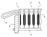
以下、本発明の実施の形態について、図面を参照して詳細に説明する。まず、図6により回転電機の固定子1の基本的構造を説明する。
Hereinafter, embodiments of the present invention will be described in detail with reference to the drawings. First, the basic structure of the
図6において、固定子1は、円筒状を成す鉄心2を有する。この固定子鉄心2は、環状の珪素鋼板を積層して全体として円筒状に形成されるており、所定の厚み毎に図示しないスペーサを介在させて径方向の通風ダクト3を形成している。そして、両側の固定子押さえ板4を介してスタッドボルト5によって一体的に固定される。
In FIG. 6, the
この固定子鉄心の内周面(図6では上面))には、軸方向に沿うコイル用のスロット6が複数本、全周にわたって所定間隔で形成されている。このスロット6は、図1で示すように、固定子コイル8を収容するもので、固定子鉄心2の内周面(図示上面)への開溝部は、コイル固定用の楔9により覆われている。すなわち、スロット6の開溝部(図示上部)の両内側壁には、このスロット6の長さ方向に沿って係合溝(楔溝)7が形成されており、コイル固定用の楔9は、その両側部が係合溝7内に係合した状態でスロット6の開溝部を覆っている。この楔9は、スロット6の開溝部を覆った状態で、その裏面によりスペーサ10を介してスロット6内に収容されたコイル8を固定する。このコイル固定用の楔9の材質としては、ポリエステルガラスマット積層板や、エポキシ鉄粉ガラスマット等が採用されている。
On the inner peripheral surface (upper surface in FIG. 6) of the stator iron core, a plurality of
ここで、前述した係合溝(以下、楔溝として説明する)7の内部(図示左/右端)には、図2及び図3で示すように、凹部7A-1が形成されている。この凹部7A-1は、楔溝7に係合した楔9の幅方向(図示水平方向)に対して所定角度傾斜している。また、この凹部7A-1は、楔溝7の長さ方向に沿って形成されている。この凹部7A-1の傾斜方向は、鉄心2の外周(図示下方)方向に向った傾斜方向とする。なお、このように傾斜した凹部7A-1を形成することにより、図3で示すように、その根元部分には相対的に突部7A-2が形成される。
Here, as shown in FIGS. 2 and 3, a
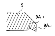
また、楔9の両側部は、前述のように楔溝7内に挿入され、係合するが、この両側部の先端部(左/右端)等には、図2及び図7で示すような突部9A-1を設ける。この突部9A-1は、図2で示すように、楔9の両側部が楔溝7に係合した状態で、凹部7A-1内に挿入可能なように、図4で示すように、前述した凹部7A-1の傾斜方向と同じ方向に傾斜して形成される。この突部9A-1も、楔9の長さ方向に沿って形成されている。なお、このように傾斜した突部9A-1を形成することにより、その根元部分には相対的に凹部9A-2が形成される。
Further, both side portions of the
このように形成した楔溝7に対して、楔溝7Aの凹部7A-1にコイル固定用楔9の凸部9A-1が入り込むようにコイル固定用楔9を軸方向から挿入し、コイル8を固定する。
The
次に、上述のように形成した固定子1を図示しない含浸タンク内でレジンの含浸処理を行い、引き揚げてから乾燥凝固させる。引き揚げる際のスロット6の上下方向が図1と同様の方向、もしくはそれから90度回転している場合は、固定子1を引き揚げたとき楔溝7の凹部7A-1にレジンが溜まることによってレジンの流失を防ぐことができる。また、楔溝7の凹部7A-1にコイル固定用楔9の凸部9A-1が入り込む形状となっているため、7A-1に溜まったレジンとコイル固定用楔9の凸部は広い接触面積で接触した状態で乾燥凝固し、コイル固定用楔9と鉄心1との間を強固に固定する。
Next, the
引き揚げる際のスロット6の上下方向が図1と逆向きの場合には、コイル固定用楔9の凸部9A-1の根元に形成される凹部9A-2にレジンが溜まりレジンの流失を防ぐことができる。また、レジン溜まりに楔溝7の凹部7A-1の根元に形成される凸部7A-2が入り込むため広い接触面積を持ったまま乾燥凝固し、コイル固定用楔9と鉄心1との間を強固に固定する。
When the up-and-down direction of the
以上述べたように、本実施の形態によれば楔溝7に凹部7A-1、及びコイル固定用楔9に凸部9A-1を設けることによって、レジン含浸時にレジン溜まりを形成してレジンの流失を防ぐと共に、レジン溜まりと楔溝7及びコイル固定用楔9の接触面積を広くすることができる。すなわち、楔溝7に楔9を挿入したときに、楔9の突部9A-1の先端が、楔溝7に凹部7A-1の入り口平面より内側に入り込むので、突部9A-1の先端は凹部7A-1に貯まったレジンの中に入るので、確実に固定できるようになる。これらの結果、従来以上に高い固定力を得て、コイル固定用楔9の楔溝7からの落下を防ぐことができる。
As described above, according to the present embodiment, the
次に、図5で示す実施の形態を説明する。本実施形態と前述の実施形態との相違点は楔溝7の凹部7A-1、及びコイル固定用楔9の凸部9A-1の傾斜方向を変えたことにある。すなわち、本実施の形態では、楔溝7の凹部7A-1及びコイル固定用楔9の凸部9A-1の傾斜方向を、鉄心2の内周(図示上方)方向に向って傾斜させたものである。
Next, the embodiment shown in FIG. 5 will be described. The difference between this embodiment and the above-mentioned embodiment is that the inclination directions of the
本実施の形態において、含浸タンクからの引き上げ時に、コイル固定用楔の凸部9A-1の根元に形成される凹部9A-2にレジンが溜まりレジンの流失を防ぐ。また、レジン溜まりに楔溝7の凹部7A-1の根元に形成される凸部7A-2が入り込むため広い接触面積を持ったまま乾燥凝固し、コイル固定用楔9と鉄心1との間を強固に固定する。
In the present embodiment, when the resin is pulled up from the impregnation tank, the resin accumulates in the
また、引き揚げる際のスロット6の上下方向が、図5と逆向きもしくはそれから90度回転している場合には、楔溝7の凹部7A-1にレジンが溜まりレジンの流失を防ぐ。また、レジン溜まりにコイル固定用楔9に凸部9A-1が入り込むため広い接触面積を持ったまま乾燥凝固し、コイル固定用楔9と鉄心1との間を強固に固定する。
Further, when the up-down direction of the
本発明のいくつかの実施形態を説明したが、これらの実施形態は例として提示したものであり、発明の範囲を限定することは意図していない。これら新規な実施形態は、その他のさまざまな形態で実施されることが可能であり、発明の要旨を逸脱しない範囲で、種々の省略、置き換え、変更を行うことができる。これらの実施形態やその変形は、発明の範囲や要旨に含まれると共に、特許請求の範囲に記載された発明とその均等の範囲に含まれる。 Although several embodiments of the present invention have been described, these embodiments have been presented by way of example and are not intended to limit the scope of the invention. These novel embodiments can be implemented in various other forms, and various omissions, replacements, and changes can be made without departing from the scope of the invention. These embodiments and modifications thereof are included in the scope and gist of the invention, and are included in the invention described in the claims and the equivalents thereof.
1・・・固定子
2・・・鉄心
6・・・スロット
7・・・係合溝(楔溝)
7A-1・・・凹部
8・・・コイル
9・・・楔
9A-1・・・凸部
DESCRIPTION OF
7A-1 ...
Claims (2)
前記係合溝の内部には、この係合溝に係合した前記楔の幅方向に対して前記鉄心の外周方向に向って所定角度傾斜した凹部が、またこの凹部の根元部分には凹部に対して相対的に形成された突部が、この係合溝の長さ方向に沿って形成され、
前記楔の前記両側部には、前記係合溝に係合した状態で、前記傾斜した凹部内に挿入可能な形状に傾斜した突部が、この突部の根元部には前記傾斜した凹部の根元に相対的に形成された突部と係合する凹部が、この楔の長さ方向に沿って形成された
ことを特徴とする回転電機の固定子。 A slot for the coil is formed along the axial direction on the inner peripheral surface of the cylindrical iron core, and the length direction of the slot is formed on both inner side walls of the slot of the slot to the inner peripheral surface of the core. Of the rotating electrical machine that is provided with a coil fixing wedge that covers the open groove portion of the slot with both sides engaged in the engagement groove, and is subjected to resin impregnation treatment. A stator,
Inside the engagement groove, there is a recess inclined at a predetermined angle toward the outer peripheral direction of the iron core with respect to the width direction of the wedge engaged with the engagement groove. Protrusions that are formed relatively to each other are formed along the length direction of the engagement groove,
On both sides of the wedge, there are protrusions that are slanted in a shape that can be inserted into the slanted recesses while being engaged with the engaging grooves, and at the roots of the protrusions are the slanted recesses. A stator for a rotating electrical machine , wherein a recess that engages with a protrusion formed relatively at the base is formed along the length direction of the wedge.
前記係合溝の内部には、この係合溝に係合した前記楔の幅方向に対して前記鉄心の内周方向に向って所定角度傾斜した凹部が、またこの凹部の根元部分には凹部に対して相対的に形成された突部が、この係合溝の長さ方向に沿って形成され、
前記楔の前記両側部には、前記係合溝に係合した状態で、前記傾斜した凹部内に挿入可能な形状に傾斜した突部が、この突部の根元部には前記傾斜した凹部の根元に相対的に形成された突部と係合する凹部が、この楔の長さ方向に沿って形成された
ことを特徴とする回転電機の固定子。 A slot for the coil is formed along the axial direction on the inner peripheral surface of the cylindrical iron core, and the length direction of the slot is formed on both inner side walls of the slot of the slot to the inner peripheral surface of the core. Of the rotating electrical machine that is provided with a coil fixing wedge that covers the open groove portion of the slot with both sides engaged in the engagement groove, and is subjected to resin impregnation treatment. A stator,
Inside the engagement groove, there is a recess inclined at a predetermined angle toward the inner peripheral direction of the iron core with respect to the width direction of the wedge engaged with the engagement groove, and a recess is formed at the root of the recess. Is formed along the length direction of the engagement groove,
On both sides of the wedge, there are protrusions that are slanted in a shape that can be inserted into the slanted recesses while being engaged with the engaging grooves, and at the roots of the protrusions are the slanted recesses. A recess that engages with a protrusion formed relative to the base was formed along the length of the wedge.
A stator of a rotating electrical machine.
Priority Applications (3)
| Application Number | Priority Date | Filing Date | Title |
|---|---|---|---|
| JP2013026572A JP6039452B2 (en) | 2013-02-14 | 2013-02-14 | Rotating electric machine stator |
| CN201310757257.7A CN103997139B (en) | 2013-02-14 | 2013-12-20 | The stator of electric rotating machine |
| IN80DE2014 IN2014DE00080A (en) | 2013-02-14 | 2014-01-10 |
Applications Claiming Priority (1)
| Application Number | Priority Date | Filing Date | Title |
|---|---|---|---|
| JP2013026572A JP6039452B2 (en) | 2013-02-14 | 2013-02-14 | Rotating electric machine stator |
Publications (2)
| Publication Number | Publication Date |
|---|---|
| JP2014158316A JP2014158316A (en) | 2014-08-28 |
| JP6039452B2 true JP6039452B2 (en) | 2016-12-07 |
Family
ID=51311195
Family Applications (1)
| Application Number | Title | Priority Date | Filing Date |
|---|---|---|---|
| JP2013026572A Expired - Fee Related JP6039452B2 (en) | 2013-02-14 | 2013-02-14 | Rotating electric machine stator |
Country Status (3)
| Country | Link |
|---|---|
| JP (1) | JP6039452B2 (en) |
| CN (1) | CN103997139B (en) |
| IN (1) | IN2014DE00080A (en) |
Families Citing this family (6)
| Publication number | Priority date | Publication date | Assignee | Title |
|---|---|---|---|---|
| CN104319927B (en) | 2014-10-11 | 2016-04-27 | 新疆金风科技股份有限公司 | There is motor slot wedge and the combination unit of hermetically-sealed construction |
| CN104319911B (en) * | 2014-10-11 | 2017-03-22 | 新疆金风科技股份有限公司 | Motor iron core with sealing structure and combination device |
| KR20170138105A (en) * | 2016-06-07 | 2017-12-15 | 뉴모텍(주) | Spoke type rotor |
| US10868456B2 (en) * | 2018-05-31 | 2020-12-15 | Siemens Energy, Inc. | False tooth assembly for generator stator core |
| CN112600331A (en) * | 2020-11-27 | 2021-04-02 | 超音速智能技术(杭州)有限公司 | Small-sized motor rotor preventing rotor winding from being thrown out |
| JP2023146831A (en) * | 2022-03-29 | 2023-10-12 | ニデック株式会社 | Stator and wedge insertion device |
Family Cites Families (7)
| Publication number | Priority date | Publication date | Assignee | Title |
|---|---|---|---|---|
| JPS5582050U (en) * | 1978-11-30 | 1980-06-06 | ||
| JPS59189448U (en) * | 1983-06-02 | 1984-12-15 | 株式会社東芝 | AC electric machine stator |
| JPS61247256A (en) * | 1985-04-25 | 1986-11-04 | Toshiba Corp | Fixing method for coil for rotary electric machine |
| JP2003079087A (en) * | 2001-09-05 | 2003-03-14 | Tma Electric Corp | Dynamo-electric stator |
| JP2009011110A (en) * | 2007-06-29 | 2009-01-15 | Nishishiba Electric Co Ltd | Stator for rotary electric machine |
| DE102010039381A1 (en) * | 2010-08-17 | 2012-02-23 | Siemens Aktiengesellschaft | Electric machine e.g. direct-driven wind generator, for use in ore mill, has active component whose full depth teeth and half depth teeth are mechanically connected with each other by anchor element |
| GB2503480A (en) * | 2012-06-28 | 2014-01-01 | Cummins Generator Technologies | Wedging arrangement for electrical machine |
-
2013
- 2013-02-14 JP JP2013026572A patent/JP6039452B2/en not_active Expired - Fee Related
- 2013-12-20 CN CN201310757257.7A patent/CN103997139B/en active Active
-
2014
- 2014-01-10 IN IN80DE2014 patent/IN2014DE00080A/en unknown
Also Published As
| Publication number | Publication date |
|---|---|
| JP2014158316A (en) | 2014-08-28 |
| CN103997139A (en) | 2014-08-20 |
| IN2014DE00080A (en) | 2015-06-12 |
| CN103997139B (en) | 2017-03-01 |
Similar Documents
| Publication | Publication Date | Title |
|---|---|---|
| JP6039452B2 (en) | Rotating electric machine stator | |
| JP5667243B2 (en) | Manufacturing method of electric motor stator having resin molded part, electric motor stator and electric motor | |
| CN111279585A (en) | Rotor and method for producing a rotor | |
| US10868455B2 (en) | Rotor of a current-activated electric machine having an improved slot filling | |
| JP2009131087A (en) | Rotor of rotating electrical machine and manufacturing method of same | |
| JP2017184520A (en) | Stator of rotary electric machine | |
| JP6421153B2 (en) | Manufacturing method of rotating electrical machine | |
| US6242833B1 (en) | Wound cover arrangement for an electric motor rotor | |
| JP2009050151A (en) | Capped stator core wedge, and related method | |
| WO2018100666A1 (en) | Stator for rotary electric machine | |
| KR101758807B1 (en) | Supporter for stator | |
| JP6686325B2 (en) | Method of fixing stator coil of stator of rotating electric machine | |
| JP5453880B2 (en) | motor | |
| JP2009207334A5 (en) | ||
| JP2014138429A (en) | Rotary electric machine | |
| JP2014110740A (en) | Stator for rotary electric machine | |
| JP2008029102A (en) | Rotator for vehicle alternator and its manufacturing method | |
| JP6249407B2 (en) | Rotating electric machine stator and method of manufacturing rotating electric machine stator | |
| JP2005312189A (en) | Rotor for dynamo-electric machine | |
| JP5941836B2 (en) | Rotating electrical machine rotor | |
| JP6478787B2 (en) | Rotating electric machine stator and method of manufacturing rotating electric machine stator | |
| JP6477448B2 (en) | Motor coil structure | |
| JP2003079087A (en) | Dynamo-electric stator | |
| JP6669004B2 (en) | Rotating electric machine | |
| CN108028569B (en) | Motor and manufacturing method |
Legal Events
| Date | Code | Title | Description |
|---|---|---|---|
| A621 | Written request for application examination |
Free format text: JAPANESE INTERMEDIATE CODE: A621 Effective date: 20150227 |
|
| A977 | Report on retrieval |
Free format text: JAPANESE INTERMEDIATE CODE: A971007 Effective date: 20160205 |
|
| A131 | Notification of reasons for refusal |
Free format text: JAPANESE INTERMEDIATE CODE: A131 Effective date: 20160308 |
|
| A521 | Request for written amendment filed |
Free format text: JAPANESE INTERMEDIATE CODE: A523 Effective date: 20160509 |
|
| TRDD | Decision of grant or rejection written | ||
| A01 | Written decision to grant a patent or to grant a registration (utility model) |
Free format text: JAPANESE INTERMEDIATE CODE: A01 Effective date: 20161101 |
|
| A61 | First payment of annual fees (during grant procedure) |
Free format text: JAPANESE INTERMEDIATE CODE: A61 Effective date: 20161104 |
|
| R150 | Certificate of patent or registration of utility model |
Ref document number: 6039452 Country of ref document: JP Free format text: JAPANESE INTERMEDIATE CODE: R150 |
|
| R250 | Receipt of annual fees |
Free format text: JAPANESE INTERMEDIATE CODE: R250 |
|
| R250 | Receipt of annual fees |
Free format text: JAPANESE INTERMEDIATE CODE: R250 |
|
| LAPS | Cancellation because of no payment of annual fees |