JP6039149B2 - Storage apparatus and control method thereof - Google Patents

Storage apparatus and control method thereof Download PDF

Info

Publication number
JP6039149B2
JP6039149B2 JP2015127702A JP2015127702A JP6039149B2 JP 6039149 B2 JP6039149 B2 JP 6039149B2 JP 2015127702 A JP2015127702 A JP 2015127702A JP 2015127702 A JP2015127702 A JP 2015127702A JP 6039149 B2 JP6039149 B2 JP 6039149B2
Authority
JP
Japan
Prior art keywords
area
data
control information
page
address
Prior art date
Legal status (The legal status is an assumption and is not a legal conclusion. Google has not performed a legal analysis and makes no representation as to the accuracy of the status listed.)
Active
Application number
JP2015127702A
Other languages
Japanese (ja)
Other versions
JP2015201233A (en
Inventor
講平 鑪
講平 鑪
江口 賢哲
賢哲 江口
竹内 久治
久治 竹内
Current Assignee (The listed assignees may be inaccurate. Google has not performed a legal analysis and makes no representation or warranty as to the accuracy of the list.)
Hitachi Ltd
Original Assignee
Hitachi Ltd
Priority date (The priority date is an assumption and is not a legal conclusion. Google has not performed a legal analysis and makes no representation as to the accuracy of the date listed.)
Filing date
Publication date
Application filed by Hitachi Ltd filed Critical Hitachi Ltd
Priority to JP2015127702A priority Critical patent/JP6039149B2/en
Publication of JP2015201233A publication Critical patent/JP2015201233A/en
Application granted granted Critical
Publication of JP6039149B2 publication Critical patent/JP6039149B2/en
Active legal-status Critical Current
Anticipated expiration legal-status Critical

Links

Images

Description

本発明は、記憶デバイスで構成されたボリュームのデータ配置を管理するためのストレージ装置及びその制御方法に関する。   The present invention relates to a storage apparatus for managing data arrangement of a volume composed of storage devices and a control method therefor.

ストレージサブシステムあるいはストレージ装置として、記憶デバイスに、例えば、ディスクドライブを用いたものが知られている。記憶デバイスに対するデータの入出力処理を制御する場合、ディスクのヘッドを位置決めすることが行われている。   As a storage subsystem or storage apparatus, a storage device using, for example, a disk drive is known. When controlling the data input / output processing for the storage device, the head of the disk is positioned.

例えば、特許文献1によると、記憶デバイスで構成されたボリュームは一つまたは複数のトラックを備えている。記憶デバイスの実記憶領域は、トラック内の先頭に制御情報部(ホームアドレス、レコード0)があり、その後ろにデータ部(レコード1、レコード2、・・・)が配置されている。メインフレーム(MF)ホスト計算機が、トラックのリードまたはライトをストレージコントローラに要求した場合、ストレージコントローラは、リードコマンドまたはライトコマンドに従ってディスクから、トラックを読み出し、トラックの制御情報部の値(ホームアドレス)を読んで、トラックの位置情報を確認し、トラックに対するヘッドの位置決めが正しく行われたことを確認した後に、データ部に対してリードまたはライトアクセスを実施する。   For example, according to Patent Document 1, a volume configured with a storage device includes one or a plurality of tracks. The real storage area of the storage device has a control information part (home address, record 0) at the head of the track, and a data part (record 1, record 2,...) Behind it. When the mainframe (MF) host computer requests the storage controller to read or write the track, the storage controller reads the track from the disk according to the read command or the write command, and the value (home address) of the control information section of the track , The position information of the track is confirmed, and after confirming that the head is correctly positioned with respect to the track, the data portion is read or written.

米国特許公報第5506979号US Pat. No. 5,506,979

近年、オンライン商取引の活発化に伴い、ネットワークに接続されたストレージ装置に対して発行されるリードまたはライトアクセスの性能向上が望まれる。こうした環境下では、前述したストレージコントローラが、トラックの位置情報を確認する処理を省き、データ部のみをディスクに対して読み書きすることで、リードアクセスまたはライトアクセス処理の高速化を行う。   In recent years, along with the activation of online commerce, it is desired to improve the performance of read or write access issued to storage devices connected to a network. Under such an environment, the storage controller described above omits the process of confirming the track position information, and reads / writes only the data portion to / from the disk, thereby speeding up the read access or write access process.

例えば、ストレージコントローラが、ホスト計算機から、あるトラックに対するリードアクセスまたはライトアクセスを受領した場合に、このトラック内の制御情報の値を参照せず、トラックの先頭にディスクのヘッドを位置づける処理が正しく行われたことを確認する処理を省くときには、ディスクからストレージコントローラへの制御情報部の転送は不要となり、リードアクセスまたはライトアクセス処理を高速化できる。   For example, when the storage controller receives a read access or write access to a track from the host computer, the process of positioning the head of the disk at the beginning of the track is correctly performed without referring to the control information value in this track. When the process of confirming the change is omitted, the transfer of the control information section from the disk to the storage controller is not necessary, and the read access or write access process can be speeded up.

しかし、特許文献1に記載されている、ボリュームのデータ配置を採用したのでは、ストレージコントローラが、ディスクからデータ部のみを読み出すようにしたとしても、ディスクのヘッドを、トラックの先頭にある制御情報部の位置をスキップして、データ部に位置付ける処理がオーバヘッドとなる。   However, when the volume data arrangement described in Patent Document 1 is adopted, even if the storage controller reads only the data portion from the disk, the control information at the head of the track is moved to the head of the disk. The process of skipping the position of the part and positioning it in the data part is overhead.

本発明の目的は、リード/ライトアクセスの性能を向上させることができるストレージ装置及びその制御方法を提供することにある。   An object of the present invention is to provide a storage apparatus capable of improving the performance of read / write access and a control method thereof.

前記目的を達成するために、本発明は、複数の一定サイズのページにて形成される仮想的な記憶領域である仮想ボリュームと、前記仮想ボリューム上にデータを格納するデータ部を纏めたデータ領域と、前記データ部へのアクセスに用いられる制御情報を格納する制御情報部を纏めた制御情報領域と、を形成するストレージコントローラと、前記仮想ボリュームに実記憶領域を提供する記憶媒体と、を備え、前記ストレージコントローラは、前記仮想ボリュームを設定後、当該仮想ボリュームの容量を一定の第1のサイズの前記データ領域と一定の第2のサイズの前記制御情報領域とを備えたグループの単位で拡張し、前記仮想ボリューム上の第1のデータ部を対象とするライト要求があった場合に、前記第1のサイズと前記第2のサイズとに基づいて、前記第1のデータ部を含む第1のページへの実記憶領域の割り当ての有無を判断し、当該割り当てが行われていない場合は前記第1のページに実記憶領域を割り当て、前記第1のデータ部へのアクセスに用いられる制御情報を格納する第1の制御情報部を含む第2のページへの実記憶領域の割り当ての有無を判断し、当該割り当てが行われていない場合は前記第2のページに実記憶領域を割り当て、前記仮想ボリュームと前記実記憶領域のそれぞれにおける前記データ領域と前記制御情報領域の配置の相違に基づいて、前記仮想ボリュームの前記データ領域に対する上位装置からのアクセス先アドレスに対応する、前記実記憶領域における前記データ領域の対応アドレスを算出することを特徴とするストレージ装置。   In order to achieve the above object, the present invention provides a data area in which a virtual volume, which is a virtual storage area formed by a plurality of pages of a certain size, and a data section for storing data on the virtual volume are collected. And a storage controller for forming a control information area for storing control information used to access the data part, and a storage medium for providing a real storage area for the virtual volume. The storage controller sets the virtual volume, and then expands the capacity of the virtual volume in units of a group including the data area having a certain first size and the control information area having a certain second size. And when there is a write request for the first data part on the virtual volume, the first size and the second size Based on whether the real storage area is allocated to the first page including the first data portion, and if the allocation is not performed, the real storage area is allocated to the first page, When it is determined whether or not the real storage area is allocated to the second page including the first control information section for storing the control information used for accessing the first data section, and the allocation is not performed. A real storage area is allocated to the second page, and based on a difference in arrangement of the data area and the control information area in each of the virtual volume and the real storage area, an upper device for the data area of the virtual volume A storage apparatus that calculates a corresponding address of the data area in the real storage area corresponding to an access destination address of the storage area.

本発明によれば、制御情報部を参照する必要がない場合でも、リード/ライトアクセスの性能を向上させることができる。   According to the present invention, read / write access performance can be improved even when it is not necessary to refer to the control information section.

ストレージシステムの全体構成を示すブロック構成図である。1 is a block configuration diagram showing the overall configuration of a storage system. ストレージコントローラ内で実行するマイクロプログラムの構成を示す構成図である。It is a block diagram which shows the structure of the microprogram performed within a storage controller. ストレージ装置内の論理構成を示す構成図である。It is a block diagram which shows the logical structure in a storage apparatus. HDEV番号とLDEV番号との対応関係を管理するための管理テーブルの構成図である。It is a block diagram of a management table for managing the correspondence between HDEV numbers and LDEV numbers. LDEV番号とボリューム属性及びボリューム容量の対応関係を管理するための管理テーブルの構成図である。It is a block diagram of a management table for managing the correspondence between LDEV numbers, volume attributes, and volume capacities. LDEV番号とディスク番号との対応関係を管理するための管理テーブルの構成図である。It is a block diagram of a management table for managing the correspondence between LDEV numbers and disk numbers. LDEV番号とプール番号との対応関係を管理するための管理テーブルの構成図である。It is a block diagram of a management table for managing the correspondence between LDEV numbers and pool numbers. プール番号とディスク番号との対応関係を管理するための管理テーブルの構成図である。It is a block diagram of the management table for managing the correspondence of a pool number and a disk number. 3390形式のLDEV内のデータ配置を説明するための構成図である。It is a block diagram for demonstrating the data arrangement | positioning in LDEV of 3390 format. 3390形式のLDEV内のデータ配置と実億領域上のデータ配置を説明するための構成図である。It is a block diagram for demonstrating the data arrangement | positioning in LDEV of 3390 format, and the data arrangement | positioning in a real billion area | region. 分散ユーザデータ領域と分散制御情報領域のサイズを管理するための管理テーブルの構成図である。It is a block diagram of the management table for managing the size of a distributed user data area and a distributed control information area. 分散ユーザデータ領域と分散制御情報領域のアドレスを管理するための管理テーブルの構成図である。It is a block diagram of the management table for managing the address of a distributed user data area and a distributed control information area. 第1実施例におけるアドレス変換処理を説明するためのフローチャートである。It is a flowchart for demonstrating the address conversion process in 1st Example. 3390‐A形式のLDEV内のデータ配置を説明するための構成図である。It is a block diagram for demonstrating the data arrangement | positioning in LDEV of 3390-A format. シリンダグループ内の構成を説明するための構成図である。It is a block diagram for demonstrating the structure in a cylinder group. 3390形式のLDEV上のアドレスと3390‐A形式のLDEV上のアドレスとの対応関係を説明するための構成図である。It is a block diagram for explaining a correspondence relationship between an address on an LDEV in 3390 format and an address on an LDEV in 3390-A format. 分散ユーザデータ領域と分散制御情報領域のサイズを管理するための管理テーブルの構成図である。It is a block diagram of the management table for managing the size of a distributed user data area and a distributed control information area. 分散ユーザデータ領域と分散制御情報領域のアドレスを管理するための管理テーブルの構成図である。It is a block diagram of the management table for managing the address of a distributed user data area and a distributed control information area. 3390‐A形式のLDEVの容量拡張処理を示すフローチャートである。10 is a flowchart showing a capacity expansion process of an LDEV in the 3390-A format. 容量拡張後における3390形式のLDEV上のアドレスと3390‐A形式のLDEV上のアドレスとの対応関係を説明するための構成図である。It is a block diagram for explaining the correspondence between addresses on LDEV in 3390 format and addresses on LDEV in 3390-A format after capacity expansion. 第2実施例におけるアドレス変換処理を説明するためのフローチャートである。It is a flowchart for demonstrating the address conversion process in 2nd Example. 第3実施例におけるHDEVとLDEVとの関係を説明するための構成図である。It is a block diagram for demonstrating the relationship between HDEV and LDEV in 3rd Example. 第3実施例における分散ユーザデータ領域と分散制御情報領域のアドレスを管理するための管理テーブルの構成図である。It is a block diagram of the management table for managing the address of the distributed user data area and the distributed control information area in the third embodiment. 第4実施例におけるコピー処理を説明するためのフローチャートである。It is a flowchart for demonstrating the copy process in 4th Example. ページ管理テーブルの構成図である。It is a block diagram of a page management table. ページ管理ディレクトリの構成図である。It is a block diagram of a page management directory. 第5実施例におけるMFホストライトコマンド処理を説明するためのフローチャートである。It is a flowchart for demonstrating MF host write command processing in 5th Example. 第6実施例におけるコピーデータ受信処理を説明するためのフローチャートである。It is a flowchart for demonstrating the copy data reception process in 6th Example.

以下、本発明の実施例を説明する。   Examples of the present invention will be described below.

なお、以下の説明では、「管理テーブル」等の表現にて各種情報を説明することがあるが、各種情報は、テーブル以外のデータ構造で表現されていてもよい。また、データ構造に依存しないことを示すために「管理テーブル」を「管理情報」と呼ぶことができる。   In the following description, various types of information may be described using an expression such as “management table”, but the various types of information may be expressed using a data structure other than a table. Further, the “management table” can be referred to as “management information” to indicate that it does not depend on the data structure.

また、以後の説明では、「プログラム」を主語として処理を説明する場合があるが、プログラムは、プロセッサ例えば、CPU(Central Processing Unit)によって実行されることで、定められた処理を、適宜に記憶資源(例えばメモリ)及び通信インタフェース装置(例えば通信ポート)を用いながら行うため、処理の主語がプロセッサとされてもよい。プロセッサは、CPUの他に専用ハードウェアを有していても良い。コンピュータプログラムは、プログラムソースから各計算機にインストールされても良い。プログラムソースは、例えば、プログラム配布サーバ又は記憶メディアであっても良い。   In the following description, the process may be described using “program” as a subject. However, the program is executed by a processor, for example, a CPU (Central Processing Unit), so that a predetermined process is appropriately stored. Since the processing is performed using resources (for example, memory) and communication interface devices (for example, communication ports), the subject of processing may be a processor. The processor may have dedicated hardware in addition to the CPU. The computer program may be installed on each computer from a program source. The program source may be, for example, a program distribution server or a storage medium.

また、各要素例えば、LDEV(Logical DEVice)は、番号などで識別可能であるが、識別可能な情報であれば、名前など他種の識別情報が用いられても良い。   Each element, for example, LDEV (Logical Device) can be identified by a number or the like, but other types of identification information such as a name may be used as long as it is identifiable information.

以下、図を用いて、本発明の実施例を説明する。以下の図中、同一の部分には同一の符号を付加する。ただし、本発明が本実施例に制限されることは無く、本発明の思想に合致するあらゆる応用例が本発明の技術的範囲に含まれる。また、特に限定しない限り、各構成要素は複数でも単数でも構わない。   Hereinafter, embodiments of the present invention will be described with reference to the drawings. In the following drawings, the same parts are denoted by the same reference numerals. However, the present invention is not limited to this embodiment, and any application examples that meet the idea of the present invention are included in the technical scope of the present invention. Further, unless specifically limited, each component may be plural or singular.

<ストレージシステムの全体構成>   <Overall configuration of storage system>

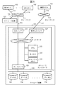
図1に、ストレージシステムの全体構成を示す。   FIG. 1 shows the overall configuration of the storage system.

図1において、ストレージシステムは、例えば、複数のストレージ装置101と、複数のメインフレーム(MF)ホスト計算機102と、管理ホスト計算機103とを備える計算機システムとして構成される。   In FIG. 1, the storage system is configured as a computer system including a plurality of storage apparatuses 101, a plurality of mainframe (MF) host computers 102, and a management host computer 103, for example.

各ストレージ装置101と各MFホスト計算機102は、例えば、ネットワーク111を介して接続され、複数のストレージ装置のうち一つのストレージ装置(以下、第一のストレージ装置と称することもある。)101と管理ホスト計算機103は、例えば、ネットワーク113を介して接続される。   Each storage apparatus 101 and each MF host computer 102 are connected via a network 111, for example, and managed with one storage apparatus (hereinafter also referred to as a first storage apparatus) 101 among a plurality of storage apparatuses. The host computer 103 is connected via a network 113, for example.

第1のストレージ装置101は、例えば、ネットワーク111を介して、異なるストレージ装置(以下、第二のストレージ装置と称することもある。)101に接続される。   The first storage device 101 is connected to a different storage device (hereinafter also referred to as a second storage device) 101 via the network 111, for example.

各MFホスト計算機102は、通信線114を介してネットワーク111に接続される。   Each MF host computer 102 is connected to the network 111 via a communication line 114.

各ストレージ装置101は、通信線115を介してネットワーク111に接続される。   Each storage apparatus 101 is connected to the network 111 via the communication line 115.

管理ホスト計算機103は、通信線116を介してネットワーク113に接続される。   The management host computer 103 is connected to the network 113 via the communication line 116.

第1のストレージ装置101は、通信線117を介してネットワーク113に接続される。   The first storage device 101 is connected to the network 113 via the communication line 117.

なお、上述の通信線114〜117は、例えば、メタルケーブルや光ファイバケーブル等の有線として構成される。しかし、各MFホスト計算機102と各ストレージ装置101、第1のストレージ装置101と管理計算機103、各MFホスト計算機102と管理計算機103をそれぞれ無線で接続することも可能である。この場合は、通信線114〜117は省略される。   The communication lines 114 to 117 described above are configured as wires such as metal cables and optical fiber cables, for example. However, each MF host computer 102 and each storage device 101, the first storage device 101 and the management computer 103, and each MF host computer 102 and the management computer 103 can be connected wirelessly. In this case, the communication lines 114 to 117 are omitted.

また、ネットワーク111とネットワーク113は、共通のネットワークであっても良い。各ネットワーク111、113は、通信ネットワークであり、例えば、SAN(Storage Area Network)又はLAN(Local Area Network)である。   Further, the network 111 and the network 113 may be a common network. Each of the networks 111 and 113 is a communication network and is, for example, a SAN (Storage Area Network) or a LAN (Local Area Network).

次に、各ストレージ装置101の構成を説明する。   Next, the configuration of each storage apparatus 101 will be described.

各ストレージ装置101は、例えば、一つまたは複数のストレージコントローラ131と、一つまたは複数のディスク132を備える。なお、各ストレージ装置101は同一の構成であるので、以下、第一のストレージ装置101の構成について説明する。   Each storage device 101 includes, for example, one or more storage controllers 131 and one or more disks 132. Since each storage apparatus 101 has the same configuration, the configuration of the first storage apparatus 101 will be described below.

一つまたは複数のディスク132には、データを格納する記憶デバイスとして、少なくとも、SSD(Solid State Drive)、SAS(Serial Attached SCSI)−HDD(Hard Disk Drive)、SATA(Serial Advanced Technology Attachment)−HDDが含まれている。なお、ディスク132は、それらのうちの少なくとも1つに代えて、またはそれらに加えて、他の種類の物理的な記憶デバイスであっても良い。   The one or more disks 132 have at least SSD (Solid State Drive), SAS (Serial Attached SCSI) -HDD (Hard Disk Drive Technology), SATA (Serial Advanced Technology) as storage devices for storing data. It is included. The disk 132 may be another kind of physical storage device instead of or in addition to at least one of them.

一つまたは複数のディスク132は、例えば、ファイバチャネルケーブル等の通信線112を介して、ストレージコントローラ131に接続される。なお、複数のディスク132で、一つまたは複数のRAID(Redundant Array of Independent Disks)グループを構成することができる。   One or more disks 132 are connected to the storage controller 131 via a communication line 112 such as a fiber channel cable. Note that one or a plurality of RAID (Redundant Array of Independent Disks) groups can be configured by the plurality of disks 132.

次に、ストレージコントローラ131の構成を説明する。   Next, the configuration of the storage controller 131 will be described.

ストレージコントローラ131は、各MFホスト計算機102から受信したコマンドに従って、ディスク132に対するデータの入出力処理、即ち、ディスク132へのデータのライト(書き込み)やリード(読み出し)を制御する。   The storage controller 131 controls data input / output processing with respect to the disk 132, that is, data writing (reading) and reading (reading) to the disk 132 according to the command received from each MF host computer 102.

ストレージコントローラ131は、アクセス要求元である各MFホスト計算機102に対して、実記憶領域が既に割り当てられている状態の論理デバイス、または後述するシン・プロビジョニング機能で用いられる仮想記憶領域で構成される論理デバイスを、アクセス対象の論理デバイスあるいは論理ボリュームとして提供する。   The storage controller 131 is configured by a logical device in which a real storage area has already been allocated to each MF host computer 102 that is an access request source, or a virtual storage area used in a thin provisioning function described later. A logical device is provided as a logical device or logical volume to be accessed.

仮想記憶領域からなる論理デバイスは、実記憶領域が既に割り当て済みであってもよいし、割り当て済みでなくともよい。   In the logical device composed of the virtual storage area, the real storage area may or may not already be allocated.

この際、ストレージコントローラ131は、実記憶領域、または仮想記憶領域を、例えば、シリンダ・ヘッド番号(以下、トラック番号)によって参照したり、識別したりすることができる。   At this time, the storage controller 131 can refer to or identify the real storage area or the virtual storage area by, for example, a cylinder head number (hereinafter referred to as a track number).

ストレージコントローラ131は、例えば、記憶資源と、通信インタフェース装置(以下、インタフェース装置を「I/F」と略記)と、それらに接続されたCPU122とを有する。   The storage controller 131 includes, for example, a storage resource, a communication interface device (hereinafter, interface device is abbreviated as “I / F”), and a CPU 122 connected thereto.

記憶資源は、例えば、主メモリ123、及びキャッシュメモリ124である。   The storage resources are, for example, the main memory 123 and the cache memory 124.

通信I/Fとしては、例えば、ホストI/F121と、管理ホストI/F127と、ディスクI/F125とを備える。これら主メモリ123、キャッシュメモリ124、CPU122、ホストI/F121、管理ホストI/F127、ディスクI/F125は、バス等の通信線からなるネットワーク126を介して相互に接続される。管理ホストI/F127は、例えば、NIC(Network Interface Card)である。   As the communication I / F, for example, a host I / F 121, a management host I / F 127, and a disk I / F 125 are provided. The main memory 123, the cache memory 124, the CPU 122, the host I / F 121, the management host I / F 127, and the disk I / F 125 are connected to each other via a network 126 including a communication line such as a bus. The management host I / F 127 is, for example, a NIC (Network Interface Card).

各MFホスト計算機102や管理ホスト計算機103のハードウェア構成は、一般的な計算機と同じである。すなわち、各MFホスト計算機102や管理ホスト計算機103は、通信インタフェース装置と、記憶資源と、それらに接続されたCPUとを有する。通信インタフェース装置としては、例えば、ネットワーク111を介した通信を行うためのホストバスアダプタ(HBA)と、ネットワーク113を介した通信を行うためのNICである。記憶資源は、例えば、メモリや内蔵HDDで構成される。   The hardware configuration of each MF host computer 102 and management host computer 103 is the same as that of a general computer. That is, each MF host computer 102 or management host computer 103 has a communication interface device, a storage resource, and a CPU connected to them. Examples of the communication interface apparatus include a host bus adapter (HBA) for performing communication via the network 111 and a NIC for performing communication via the network 113. The storage resource is composed of, for example, a memory or a built-in HDD.

図2に、ストレージコントローラ131内で実行するマイクロプログラム231の構成を示す。   FIG. 2 shows the configuration of the microprogram 231 executed in the storage controller 131.

図2において、主メモリ123には、一つまたは複数のマイクロプログラム231がCPU122によって読み込まれる。このマイクロプログラム231には、コマンド制御部251、RAID制御部252、構成制御部253、アドレス変換部254が含まれる。CPU122が、主メモリ123に読み込まれたマイクロプログラム231内の各制御部251〜254を実行することにより、後述する種々の処理が行われる。   In FIG. 2, one or more microprograms 231 are read into the main memory 123 by the CPU 122. The microprogram 231 includes a command control unit 251, a RAID control unit 252, a configuration control unit 253, and an address conversion unit 254. When the CPU 122 executes the control units 251 to 254 in the microprogram 231 read into the main memory 123, various processes described later are performed.

キャッシュメモリ124は、例えば、各MFホスト計算機102から受信したライトデータおよびマイクロプログラム231内のRAID制御部252がディスク132から読み出したデータを一時的に記憶するバッファを構成する。   For example, the cache memory 124 constitutes a buffer that temporarily stores write data received from each MF host computer 102 and data read from the disk 132 by the RAID control unit 252 in the microprogram 231.

ホストI/F121は、ネットワーク111を介して、各MFホスト計算機102に接続され、各MFホスト計算機102から、アクセス要求としてアクセスコマンド(ライトコマンド又はリードコマンド)を受信し、受信したアクセスコマンドをコマンド制御部251に転送する。   The host I / F 121 is connected to each MF host computer 102 via the network 111, receives an access command (write command or read command) as an access request from each MF host computer 102, and uses the received access command as a command. Transfer to the control unit 251.

管理ホストI/F127は、ネットワーク113を介して、管理ホスト計算機103に接続され、管理ホスト計算機103から、例えば、後述するLDEVの容量拡張を行う指示や、LDEV間のデータコピー指示を受信した場合、受信した指示をコマンド制御部251または構成制御部253に転送する。   The management host I / F 127 is connected to the management host computer 103 via the network 113 and receives, for example, an LDEV capacity expansion instruction (to be described later) or a data copy instruction between LDEVs from the management host computer 103. The received instruction is transferred to the command control unit 251 or the configuration control unit 253.

ディスクI/F125は、各ディスク132と記憶資源(主メモリ123とキャッシュメモリ124)との間のデータ送受信を行う。ディスクI/F125は、通信路112を介して各ディスク132にそれぞれ接続される。   The disk I / F 125 performs data transmission / reception between each disk 132 and storage resources (main memory 123 and cache memory 124). The disk I / F 125 is connected to each disk 132 via the communication path 112.

次に、ストレージ装置101の基本的動作を簡単に説明する。   Next, the basic operation of the storage apparatus 101 will be briefly described.

ストレージコントローラ131は、ホストI/F121を介して、いずれかのMFホスト計算機102からライトコマンドを受信した場合、MFホスト計算機102から受信したライトデータをキャッシュメモリ124に記憶する。   When the storage controller 131 receives a write command from any MF host computer 102 via the host I / F 121, the storage controller 131 stores the write data received from the MF host computer 102 in the cache memory 124.

ストレージコントローラ131は、キャッシュメモリ124に記憶しているライトデータを、ディスクI/F125を介してディスク132に書き込む。なお、ストレージコントローラ131は、ライトデータをキャッシュメモリ124に記憶した時点で、ライトコマンドの処理が完了した旨をMFホスト計算機102に通知する構成でもよいし、或いは、ライトデータをディスク132に書き込んだ時点で、ライトコマンドの処理が完了した旨をMFホスト計算機102に通知する構成でもよい。   The storage controller 131 writes the write data stored in the cache memory 124 to the disk 132 via the disk I / F 125. The storage controller 131 may be configured to notify the MF host computer 102 that the write command processing has been completed when the write data is stored in the cache memory 124, or the write data is written to the disk 132. It may be configured to notify the MF host computer 102 that the processing of the write command is completed at the time.

MFホスト計算機102からリードコマンドを受信した場合、ストレージコントローラ131は、そのリードコマンドにパラメータで指定されるデータ(リード対象データ)がキャッシュメモリ124に記憶されているか否かを調べる。   When a read command is received from the MF host computer 102, the storage controller 131 checks whether data (read target data) specified by the parameter in the read command is stored in the cache memory 124.

リード対象データがキャッシュメモリ124に記憶されている場合、ストレージコントローラ131は、リード対象データをキャッシュメモリ124から読み出し、読み出したリード対象データを、ホストI/F121を介してMFホスト計算機102に送信する。一方、リード対象データがキャッシュメモリ124に記憶されていない場合は、ストレージコントローラ131は、ディスクI/F125を介して、一つまたは複数のディスク132からリード対象データを読み出し、読み出したリード対象データをキャッシュメモリ124に記憶する。その後、ストレージコントローラ131は、キャッシュメモリ124に記憶されているリード対象データを、ホストI/F121を介してMFホスト計算機102に送信する。   When the read target data is stored in the cache memory 124, the storage controller 131 reads the read target data from the cache memory 124 and transmits the read read target data to the MF host computer 102 via the host I / F 121. . On the other hand, when the read target data is not stored in the cache memory 124, the storage controller 131 reads the read target data from one or a plurality of disks 132 via the disk I / F 125, and reads the read target data. Store in the cache memory 124. Thereafter, the storage controller 131 transmits the read target data stored in the cache memory 124 to the MF host computer 102 via the host I / F 121.

<ストレージ装置内の論理構成>   <Logical configuration in storage device>

図3に、ストレージ装置101内の論理構成を示す。   FIG. 3 shows a logical configuration in the storage apparatus 101.

図3において、ストレージ装置101は、各MFホスト計算機102や管理ホスト計算機103から参照される記憶領域を構成するホスト用論理デバイスとして、一つまたは複数のホスト用論理デバイス(以下、HDEVと称することがある。)321を有する。   In FIG. 3, the storage apparatus 101 has one or more host logical devices (hereinafter referred to as HDEVs) as host logical devices constituting a storage area referred to by each MF host computer 102 or management host computer 103. There is 321).

HDEV321には、ストレージ装置101内で固有のHDEV番号が付けられ、MFホスト計算機102や管理ホスト計算機103は、HDEV番号により、HDEV321を識別する。例えば、各MFホスト計算機102上のOS331は、HDEV321に対してリードアクセスまたはライトアクセスを行う。   The HDEV 321 is assigned a unique HDEV number in the storage apparatus 101, and the MF host computer 102 and the management host computer 103 identify the HDEV 321 by the HDEV number. For example, the OS 331 on each MF host computer 102 performs read access or write access to the HDEV 321.

HDEV321は、例えば、トラックの集合(トラック1、トラック2、・・・)で構成されており、各トラックに付与されたシリンダ・ヘッド番号(トラック番号)は、各MFホスト計算機102や管理ホスト計算機103が、各トラックを識別するときの参照対象となる。   The HDEV 321 is composed of, for example, a set of tracks (track 1, track 2,...), And the cylinder head number (track number) assigned to each track is the MF host computer 102 or management host computer. Reference numeral 103 is a reference target for identifying each track.

HDEV321には、一つまたは複数の論理デバイス(以下、LDEVまたはボリュームと称することがある。)322が対応付けられている。   One or a plurality of logical devices (hereinafter sometimes referred to as LDEVs or volumes) 322 are associated with the HDEV 321.

LDEV322には、ストレージ装置101内で固有のLDEV番号が付けられ、マイクロプログラム231は、LDEV番号により、LDEV322を識別する。   The LDEV 322 is assigned a unique LDEV number in the storage apparatus 101, and the microprogram 231 identifies the LDEV 322 by the LDEV number.

LDEV322は、例えば、一つまたは複数のディスク132内の記憶領域として定義される。また、LDEV322は、複数のRAIDグループで構成される記憶領域として定義されていてもよい。   The LDEV 322 is defined as a storage area in one or a plurality of disks 132, for example. Further, the LDEV 322 may be defined as a storage area composed of a plurality of RAID groups.

LDEV322は、トラックに対応した複数のデータ部325と複数の制御情報部326から構成される。各データ部325は、トラック(トラック番号)に対応した1または複数のレコード(図示せず)で構成され、各レコードには、MFホスト計算機102がリードまたはライトするデータが格納される。各制御情報部326は、各トラックのデータ部325をアクセスするための制御情報あるいは、各トラックのデータ部325を参照または更新するための制御情報で構成される。   The LDEV 322 includes a plurality of data units 325 and a plurality of control information units 326 corresponding to tracks. Each data portion 325 is composed of one or a plurality of records (not shown) corresponding to a track (track number), and data read or written by the MF host computer 102 is stored in each record. Each control information unit 326 includes control information for accessing the data unit 325 of each track or control information for referring to or updating the data unit 325 of each track.

この際、ストレージ装置101内で、全てのトラックサイズは一定の値である。ストレージ装置101内で、全てのデータ部325と全ての制御情報部326のサイズは一定の値である。   At this time, all the track sizes in the storage apparatus 101 are constant values. In the storage apparatus 101, the sizes of all the data units 325 and all the control information units 326 are constant values.

各ディスク132には、ストレージ装置101内で固有のディスク番号がつけられ、マイクロプログラム231は、ディスク番号により、各ディスク132を識別する。   Each disk 132 is given a unique disk number in the storage apparatus 101, and the microprogram 231 identifies each disk 132 by the disk number.

また、LDEV322は、後述するシン・プロビジョニング機能で用いられる仮想ボリューム上に保存されていてもよい。   Further, the LDEV 322 may be stored on a virtual volume used in the thin provisioning function described later.

LDEV322のデータが保存される仮想ボリュームは、この仮想ボリュームに対して実記憶領域を提供するプール323と関連付けられる。   A virtual volume in which LDEV 322 data is stored is associated with a pool 323 that provides a real storage area for the virtual volume.

プール323には、ストレージ装置101内で固有のプール番号がつけられ、マイクロプログラム231は、プール番号により、プール323を識別する。   The pool 323 is assigned a unique pool number in the storage apparatus 101, and the microprogram 231 identifies the pool 323 by the pool number.

プール323は、一つまたは複数のディスク132から構成される。また、プール323は、一つまたは複数のRAIDグループから構成されていてもよい。一つまたは複数のディスク132は、ストレージ装置の内部にあってもよいし、外部にあってもよい。   The pool 323 is composed of one or a plurality of disks 132. The pool 323 may be configured from one or a plurality of RAID groups. One or a plurality of disks 132 may be inside or outside the storage apparatus.

図4に、HDEV番号とLDEV番号との対応関係を管理するための管理テーブル400の構成を示す。   FIG. 4 shows the configuration of a management table 400 for managing the correspondence between HDEV numbers and LDEV numbers.

管理テーブル400は、HDEV番号フィールド401とLDEV番号フィールド402から構成される。HDEV番号は、ストレージ装置101内でHDEV321を一意に識別するための番号であって、HDEV番号フィールド401の各エントリには、HDEV321に対応した番号が格納される。LDEV番号は、ストレージ装置101内でLDEV322を一意に識別するための番号であって、LDEV番号フィールド402の各エントリには、LDEV322に対応した番号が格納される。   The management table 400 includes an HDEV number field 401 and an LDEV number field 402. The HDEV number is a number for uniquely identifying the HDEV 321 in the storage apparatus 101, and each entry in the HDEV number field 401 stores a number corresponding to the HDEV 321. The LDEV number is a number for uniquely identifying the LDEV 322 within the storage apparatus 101, and each entry in the LDEV number field 402 stores a number corresponding to the LDEV 322.

図5に、LDEV番号とボリューム属性との対応関係を管理するための管理テーブル500の構成を示す。   FIG. 5 shows the configuration of a management table 500 for managing the correspondence between LDEV numbers and volume attributes.

管理テーブル500は、LDEV番号フィールド501とボリューム属性フィールド502及びボリューム容量フィールド503から構成される。LDEV番号は、ストレージ装置101内でLDEV322を一意に識別するための番号であって、LDEV番号フィールド501の各エントリには、LDEV322に対応した番号が格納される。ボリューム属性は、LDEV322のボリューム属性が、通常ボリュームまたは仮想ボリュームであることを特定するものであり、ボリューム属性フィールド502の各エントリには、通常ボリュームまたは仮想ボリュームの名称が格納される。   The management table 500 includes an LDEV number field 501, a volume attribute field 502, and a volume capacity field 503. The LDEV number is a number for uniquely identifying the LDEV 322 within the storage apparatus 101, and each entry in the LDEV number field 501 stores a number corresponding to the LDEV 322. The volume attribute specifies that the volume attribute of the LDEV 322 is a normal volume or a virtual volume, and each entry of the volume attribute field 502 stores the name of the normal volume or virtual volume.

LDEV322のボリューム属性が通常ボリュームであるとき、このLDEV322は、一つまたは複数のディスク132内の実記憶領域で構成されたボリュームであることを示す。   When the volume attribute of the LDEV 322 is a normal volume, this LDEV 322 indicates that the volume is composed of real storage areas in one or more disks 132.

ボリューム容量は、通常ボリュームまたは仮想ボリュームにデータを格納することができる最大容量であり、ボリューム容量フィールド503の各エントリには、通常ボリュームまたは仮想ボリュームの容量が数値で格納される。   The volume capacity is the maximum capacity in which data can be stored in the normal volume or virtual volume. Each entry in the volume capacity field 503 stores the capacity of the normal volume or virtual volume numerically.

図6に、LDEV番号とディスク番号との対応関係を管理するための管理テーブル600の構成を示す。   FIG. 6 shows the configuration of a management table 600 for managing the correspondence between LDEV numbers and disk numbers.

管理テーブル600は、LDEV322のボリューム属性が通常ボリュームであるときの管理テーブルであって、LDEV番号フィールド601とディスク番号フィールド602から構成される。LDEV番号は、ストレージ装置101内でLDEV322を一意に識別するための番号であって、LDEV番号フィールド601の各エントリには、LDEV322に対応した番号が格納される。ディスク番号は、ストレージ装置101内でディスク132を一意に識別するための番号であって、ディスク番号フィールド602の各エントリには、LDEV322を構成するディスク132の番号が格納される。   The management table 600 is a management table when the volume attribute of the LDEV 322 is a normal volume, and includes an LDEV number field 601 and a disk number field 602. The LDEV number is a number for uniquely identifying the LDEV 322 within the storage apparatus 101, and each entry in the LDEV number field 601 stores a number corresponding to the LDEV 322. The disk number is a number for uniquely identifying the disk 132 in the storage apparatus 101, and the number of the disk 132 constituting the LDEV 322 is stored in each entry of the disk number field 602.

図7に、LDEV番号とプール番号との対応関係を管理するための管理テーブル700の構成を示す。   FIG. 7 shows the configuration of a management table 700 for managing the correspondence between LDEV numbers and pool numbers.

管理テーブル700は、LDEV322のボリューム属性が仮想ボリュームであるときの管理テーブルであって、LDEV番号フィールド701とプール番号フィールド702から構成される。LDEV番号は、ストレージ装置101内でLDEV322を一意に識別するための番号であって、LDEV番号フィールド701の各エントリには、LDEV322に対応した番号が格納される。プール番号は、ストレージ装置101内でプール323を一意に識別するための番号であって、プール番号フィールド702の各エントリには、LDEV322に対応したプール323の番号が格納される。   The management table 700 is a management table when the volume attribute of the LDEV 322 is a virtual volume, and includes an LDEV number field 701 and a pool number field 702. The LDEV number is a number for uniquely identifying the LDEV 322 in the storage apparatus 101, and each entry in the LDEV number field 701 stores a number corresponding to the LDEV 322. The pool number is a number for uniquely identifying the pool 323 within the storage apparatus 101, and each entry in the pool number field 702 stores the number of the pool 323 corresponding to the LDEV 322.

図8に、プール番号とディスク番号との対応関係を管理するための管理テーブル800の構成を示す。   FIG. 8 shows the configuration of a management table 800 for managing the correspondence between pool numbers and disk numbers.

管理テーブル800は、LDEV322のボリューム属性が仮想ボリュームであるときの管理テーブルであって、プール番号フィールド801とディスク番号フィールド802から構成される。プール番号は、ストレージ装置101内でプール323を一意に識別するための番号であって、プール番号フィールド801の各エントリには、プール323に対応した番号が格納される。ディスク番号は、ストレージ装置101内でディスク132を一意に識別するための番号であって、ディスク番号フィールド602の各エントリには、プール323に実記憶領域が割り当てられるディスク132の番号が格納される。   The management table 800 is a management table when the volume attribute of the LDEV 322 is a virtual volume, and includes a pool number field 801 and a disk number field 802. The pool number is a number for uniquely identifying the pool 323 within the storage apparatus 101, and each entry in the pool number field 801 stores a number corresponding to the pool 323. The disk number is a number for uniquely identifying the disk 132 in the storage apparatus 101, and each entry of the disk number field 602 stores the number of the disk 132 to which a real storage area is allocated to the pool 323. .

本実施例は、データ部と制御情報部を異なる領域に格納、ストレージコントローラが、ディスクからデータ部のみを読み書きする場合に、前述した制御情報部の位置をスキップする処理を省き、ディスクのヘッドを直接データ部に位置付けできるようにしたものである。   In this embodiment, the data part and the control information part are stored in different areas, and when the storage controller reads / writes only the data part from the disk, the process of skipping the position of the control information part described above is omitted, and the head of the disk is omitted. It can be positioned directly in the data part.

この際、データ部を配置するユーザデータ領域と、このユーザデータ領域に連なる記憶領域であって、制御情報部を配置する制御情報領域を、それぞれ容量変更の対象となる記憶領域、例えば、容量を拡張または縮小する場合の記憶領域として管理し、記憶領域として、ユーザデータ領域と制御情報領域が並ぶデータ配置(第1データ配置)を採用するボリューム(LDEV)を3390形式のボリュームとして管理する。   At this time, a user data area in which the data part is arranged and a storage area that is connected to the user data area, and a control information area in which the control information part is arranged are respectively divided into storage areas whose capacity is changed, for example, the capacity. A volume (LDEV) that employs a data arrangement (first data arrangement) in which a user data area and a control information area are arranged is managed as a 3390 format volume as a storage area for expansion or reduction.

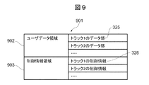
<3390形式のLDEV322内のデータ配置>
図9に、HDEV321を構成する3390形式のLDEV322内のデータ配置を示す。
<Data arrangement in LDEV 322 in 3390 format>
FIG. 9 shows the data arrangement in the 3390-format LDEV 322 constituting the HDEV 321.

図9において、LDEV322の記憶領域901は、ユーザデータ領域902と制御情報領域903から構成される。ユーザデータ領域902は、複数のデータ部(トラックに対応した1または複数のレコードを含む)325を格納する第1データ領域として構成され、制御情報領域903は、ユーザデータ領域902に連なり、かつユーザデータ領域902に格納された各データ部325をそれぞれアクセスするための制御情報で構成された制御情報部326を格納する第1制御情報領域として構成される。この際、ストレージコントローラ131は、ユーザデータ領域902に連続して制御情報領域903が配置された記憶領域901のデータ配置を第1データ配置とする第1ボリューム形式(以下、3390形式と称することもある。)でLDEV322を管理する。マイクロプログラム231は、各トラック内のデータ部325をトラック番号により識別し、各トラック内の制御情報部326をトラック番号により識別する。   In FIG. 9, the storage area 901 of the LDEV 322 includes a user data area 902 and a control information area 903. The user data area 902 is configured as a first data area for storing a plurality of data portions (including one or a plurality of records corresponding to a track) 325, and the control information area 903 is connected to the user data area 902 and is a user The data area 902 is configured as a first control information area for storing a control information section 326 configured with control information for accessing each data section 325. At this time, the storage controller 131 uses a first volume format (hereinafter also referred to as a 3390 format) in which the data layout of the storage area 901 in which the control information area 903 is placed in succession to the user data area 902 is the first data layout. The LDEV 322 is managed. The microprogram 231 identifies the data portion 325 in each track by the track number, and identifies the control information portion 326 in each track by the track number.

3390形式のLDEV322は、HDEV321内のトラック数が大きくなると、ユーザデータ領域902および制御情報領域903内のトラック数も大きくなる。即ち、3390形式のLDEV322は、容量の拡張に伴ってHDEV321内のトラック数が増加した場合、HDEV321内のトラック数の増加に応じて、ユーザデータ領域902および制御情報領域903内のトラック数も増加する。   In the 3390 format LDEV 322, as the number of tracks in the HDEV 321 increases, the number of tracks in the user data area 902 and the control information area 903 also increases. That is, when the number of tracks in the HDEV 321 increases as the capacity increases, the number of tracks in the user data area 902 and the control information area 903 increases as the number of tracks in the HDEV 321 increases. To do.

3390形式のLDEV322のデータ配置としては、ユーザデータ領域902の手前に、制御情報領域903を配置することもできる。   As the data arrangement of the LDEV 322 in the 3390 format, the control information area 903 can be arranged in front of the user data area 902.

<3390形式のLDEV322に対するライトコマンドまたはリードコマンド処理の一例>   <Example of Write Command or Read Command Processing for 3390 Format LDEV 322>

以下、MFホスト計算機102が、ホストI/F121を介して、ストレージコントローラ131に対して、ライトコマンドを要求した場合の処理を説明する。ライトコマンドのパラメータは、HDEV番号とHDEV321内のライト対象トラックのトラック番号と、ライト対象データである。   Hereinafter, processing when the MF host computer 102 requests a write command to the storage controller 131 via the host I / F 121 will be described. The parameters of the write command are the HDEV number, the track number of the write target track in the HDEV 321, and the write target data.

ストレージコントローラ131内のコマンド制御部251は、MFホスト計算機102からのライトコマンドを受信した場合、ライトコマンドのパラメータであるHDEV番号を基に管理テーブル400を参照し、HDEV番号に対応したLDEV番号を取得する。   When receiving a write command from the MF host computer 102, the command control unit 251 in the storage controller 131 refers to the management table 400 based on the HDEV number that is a parameter of the write command, and sets the LDEV number corresponding to the HDEV number. get.

コマンド制御部251は、取得したLDEV番号からLDEV322を特定し、ライト対象トラックのトラック番号を基に、特定したLDEV322上のトラック番号(HDEV321内のライト対象トラックのトラック番号と同一のトラック番号)のデータ部325のアドレスと、特定したLDEV322上のトラック番号(HDEV321内のライト対象トラックのトラック番号と同一のトラック番号)の制御情報部326のアドレスを計算する。   The command control unit 251 identifies the LDEV 322 from the acquired LDEV number, and based on the track number of the write target track, the track number on the identified LDEV 322 (the track number that is the same as the track number of the write target track in the HDEV 321) The address of the data part 325 and the address of the control information part 326 of the track number on the specified LDEV 322 (the same track number as the write target track in the HDEV 321) are calculated.

次に、コマンド制御部251は、前述したライトコマンドが、トラック番号の制御情報部326を参照する必要があるかどうかを判定する。トラック番号の制御情報部326を参照する必要がある場合、例えば、MFホスト計算機102が、制御情報部326の参照結果として、ディスクに対するヘッドの位置決め状態に関する情報の返送を求めている場合、RAID制御部252は、LDEV番号を基に管理テーブル600を参照し、制御情報部326のアドレスに基づき、一つまたは複数のディスク132から、トラック番号の制御情報部326を、キャッシュメモリ124に読み込む。コマンド制御部251は、キャッシュメモリ124に読み込まれたトラック番号の制御情報部326を参照する。   Next, the command control unit 251 determines whether or not the above-described write command needs to refer to the track number control information unit 326. When it is necessary to refer to the control information section 326 of the track number, for example, when the MF host computer 102 requests return of information regarding the head positioning state with respect to the disk as a reference result of the control information section 326, RAID control is performed. The unit 252 refers to the management table 600 based on the LDEV number, and reads the track number control information unit 326 from one or more disks 132 into the cache memory 124 based on the address of the control information unit 326. The command control unit 251 refers to the track number control information unit 326 read into the cache memory 124.

コマンド制御部251が、トラック番号の制御情報部326を参照する必要がなければ、前述した制御情報部326のリード処理は省略してもよい。   If the command control unit 251 does not need to refer to the track number control information unit 326, the above-described read processing of the control information unit 326 may be omitted.

即ち、データ部325と制御情報部326をそれぞれ異なる領域に格納し、データ部325を格納するトラックのサイズを設定した値とした場合、コマンド制御部251が、制御情報部326の制御情報を参照せずに、ディスク側でディスクのヘッドをデータ部325に直接位置づける。この場合、ディスクのヘッド位置付けにおいて、制御情報部326の領域をスキップする処理が不要となるので、ストレージコントローラ131は、制御情報部326を参照するときよりも、リードアクセスまたはライトアクセス処理を高速化できる。   That is, when the data unit 325 and the control information unit 326 are stored in different areas and the size of the track storing the data unit 325 is set to a set value, the command control unit 251 refers to the control information of the control information unit 326. Instead, the head of the disk is positioned directly on the data section 325 on the disk side. In this case, since the process of skipping the area of the control information unit 326 is unnecessary in positioning the head of the disk, the storage controller 131 speeds up the read access or write access process than when referring to the control information unit 326. it can.

次に、コマンド制御部251は、ライト対象データを、キャッシュメモリ124に書き込む。   Next, the command control unit 251 writes the write target data in the cache memory 124.

この後、RAID制御部252は、LDEV番号を基に管理テーブル600を参照し、LDEV番号に対応したディスク番号を取得し、LDEV322を構成するディスク132を特定し、データ部325のアドレスに基づき、キャッシュメモリ124上のライト対象データを特定した一つまたは複数のディスク132に書き込む。即ち、3390形式のデータ配置が実記憶領域上のデータ配置と同じである場合、アドレス変換部254によるアドレス変換で得られたアドレスを用いることなく、RAID制御部252は、コマンド制御部251の計算結果によるアドレスを用いることで、キャッシュメモリ124上のライト対象データを、特定した一つまたは複数のディスク132に書き込むことができる。   Thereafter, the RAID control unit 252 refers to the management table 600 based on the LDEV number, acquires the disk number corresponding to the LDEV number, specifies the disk 132 that configures the LDEV 322, and based on the address of the data unit 325, Write the write target data on the cache memory 124 to the specified one or more disks 132. That is, when the data arrangement in the 3390 format is the same as the data arrangement in the real storage area, the RAID control unit 252 calculates the command control unit 251 without using the address obtained by the address conversion by the address conversion unit 254. By using the address based on the result, the write target data on the cache memory 124 can be written to the specified one or more disks 132.

次に、ストレージコントローラ131は、ホストI/F121を介して、ライトコマンドの処理が完了した旨をMFホスト計算機102に通知する。   Next, the storage controller 131 notifies the MF host computer 102 through the host I / F 121 that the write command processing has been completed.

以上が、MFホスト計算機102が、ホストI/F121を介して、ストレージコントローラ131に対して、ライトコマンドを要求した場合の処理である。   The above is the processing when the MF host computer 102 requests a write command from the storage controller 131 via the host I / F 121.

次に、MFホスト計算機102が、ホストI/F121を介して、ストレージコントローラ131に対して、リードコマンドを要求した場合の処理を説明する。リードコマンドのパラメータは、HDEV番号とHDEV321内のリード対象トラックのトラック番号である。   Next, processing when the MF host computer 102 requests a read command to the storage controller 131 via the host I / F 121 will be described. The parameters of the read command are the HDEV number and the track number of the read target track in the HDEV 321.

ストレージコントローラ131内のコマンド制御部251は、MFホスト計算機102からのリードコマンドを受信した場合、リードコマンドのパラメータであるHDEV番号を基に管理テーブル400を参照し、HDEV番号に対応したLDEV番号を取得する。   When the command control unit 251 in the storage controller 131 receives a read command from the MF host computer 102, the command control unit 251 refers to the management table 400 based on the HDEV number that is a parameter of the read command, and determines the LDEV number corresponding to the HDEV number. get.

コマンド制御部251は、取得したLDEV番号でLDEV322を特定し、リード対象トラックのトラック番号(HDEV321内のリード対象トラックのトラック番号と同一のトラック番号)を基に、特定したLDEV322上のトラック番号のデータ部325のアドレスと、リード対象トラックのトラック番号(HDEV321内のリード対象トラックのトラック番号と同一のトラック番号)の制御情報部326のアドレスを計算する。   The command control unit 251 identifies the LDEV 322 with the acquired LDEV number, and based on the track number of the track to be read (the track number that is the same as the track number of the track to be read in the HDEV 321), The address of the data section 325 and the address of the control information section 326 of the track number of the read target track (the same track number as the read target track in the HDEV 321) are calculated.

次に、コマンド制御部251は、前述したリードコマンドが、トラック番号の制御情報部326を参照する必要があるかどうかを判定する。トラック番号の制御情報部326を参照する必要がある場合、RAID制御部252は、LDEV番号を基に管理テーブル600を参照し、制御情報部326のアドレスに基づき、一つまたは複数のディスク132から、トラック番号の制御情報部326を、キャッシュメモリ124に読み込む。コマンド制御部251は、キャッシュメモリ124に読み込まれたトラック番号の制御情報部326を参照する。トラック番号942の制御情報部326を参照する必要がなければ、前述した制御情報部326のリード処理は省略してもよい。   Next, the command control unit 251 determines whether or not the above-described read command needs to refer to the control information unit 326 of the track number. When it is necessary to refer to the track number control information unit 326, the RAID control unit 252 refers to the management table 600 based on the LDEV number, and from one or more disks 132 based on the address of the control information unit 326. The track number control information section 326 is read into the cache memory 124. The command control unit 251 refers to the track number control information unit 326 read into the cache memory 124. If it is not necessary to refer to the control information part 326 of the track number 942, the read processing of the control information part 326 described above may be omitted.

次に、RAID制御部252は、LDEV番号を基に管理テーブル600を参照し、LDEV番号に対応したディスク番号を取得してディスク132を特定し、データ部325のアドレスに基づき、リード対象トラックのトラック番号のデータ部325を、特定した一つまたは複数のディスク132から、キャッシュメモリ124に読み込む。   Next, the RAID control unit 252 refers to the management table 600 based on the LDEV number, acquires the disk number corresponding to the LDEV number, specifies the disk 132, and based on the address of the data unit 325, reads the read target track. The track number data portion 325 is read into the cache memory 124 from one or more specified disks 132.

ストレージコントローラ131は、キャッシュメモリ124にある、リード対象トラックのトラック番号のデータ部325を、ホストI/F121を介して、MFホスト計算機102に送信する。   The storage controller 131 transmits the data part 325 of the track number of the read target track in the cache memory 124 to the MF host computer 102 via the host I / F 121.

以上が、MFホスト計算機102が、ホストI/F121を介して、ストレージコントローラ131に対して、リードコマンドを要求した場合の処理である。   The above is the processing when the MF host computer 102 requests a read command to the storage controller 131 via the host I / F 121.

前述したリードコマンドに対する処理では、リード対象トラックのトラック番号のデータ部325または制御情報部326が、キャッシュメモリ124に既に存在していた場合、一つまたは複数のディスク132からキャッシュメモリ124に、リード対象トラックのトラック番号のデータ部325または制御情報部326を読み込む処理を省略することができる。   In the processing for the read command described above, if the data portion 325 or the control information portion 326 of the track number of the track to be read already exists in the cache memory 124, read from one or more disks 132 to the cache memory 124 is performed. The process of reading the track number data portion 325 or the control information portion 326 of the target track can be omitted.

また、リードコマンドに対する処理でも、コマンド制御部251が、制御情報部326の制御情報を参照せずに、ディスクのヘッドを直接データ部325に位置付けることができるので、ストレージコントローラ131は、制御情報部326を参照しない場合は、制御情報部326をスキップする処理が不要であるため、リードアクセスまたはライトアクセス処理を高速化できる。   Further, even in the processing for the read command, the command controller 251 can directly position the head of the disk in the data unit 325 without referring to the control information in the control information unit 326. When 326 is not referred to, the process of skipping the control information unit 326 is unnecessary, so that the read access or write access process can be speeded up.

<3390形式のLDEV322の容量拡張>   <Capacity expansion of 3390 format LDEV 322>

図10に、3390形式のLDEV322の容量拡張を実施する際の一例を示す。   FIG. 10 shows an example when the capacity expansion of the 3390 format LDEV 322 is performed.

3390形式のLDEV322の容量を変更する必要が生じた場合、例えば、図9に示す3390形式のLDEV322の容量を拡張する必要が生じた場合、アクセス要求元が、アクセス対象のボリュームを3390形式のボリュームとして認識できるとともに、コマンド制御部251が、LDEV322を、容量拡張後でも3390形式のLDEV322としてアクセスできるように、ユーザデータ領域に連続して制御情報領域を形成するデータ配置が採用される。   When it is necessary to change the capacity of the 3390-format LDEV 322, for example, when the capacity of the 3390-format LDEV 322 shown in FIG. 9 needs to be expanded, the access request source sets the volume to be accessed as a 3390-format volume. And a data arrangement in which a control information area is continuously formed in the user data area is adopted so that the command control unit 251 can access the LDEV 322 as a 3390-format LDEV 322 even after capacity expansion.

具体的には、容量拡張後における3390形式のLDEV322の記憶領域910は、分散ユーザデータ領域1001、1002と、分散制御情報領域1011、1012から構成される。   Specifically, the storage area 910 of the 3390-format LDEV 322 after capacity expansion is composed of distributed user data areas 1001 and 1002 and distributed control information areas 1011 and 1012.

即ち、容量拡張前のLDEV322の記憶領域が、分散ユーザデータ領域1001と分散制御情報領域1011で構成され、この記憶領域に、分散ユーザデータ領域1002と分散制御情報領域1012を追加する場合、分散ユーザデータ領域1001に連続して、分散ユーザデータ領域1002を、新たなに確保された記憶領域として配置し、分散ユーザデータ領域1002に連続して分散制御情報領域1011を配置し、分散制御情報領域1011に連続して、新たに確保された記憶領域として分散制御情報領域1012を配置し、記憶領域910全体として、ユーザデータ領域に連続して制御情報領域を形成するデータ配置(3390形式によるデータ配置)としている。   That is, the storage area of the LDEV 322 before capacity expansion is composed of the distributed user data area 1001 and the distributed control information area 1011. When the distributed user data area 1002 and the distributed control information area 1012 are added to this storage area, the distributed user The distributed user data area 1002 is arranged as a newly secured storage area continuously from the data area 1001, the distributed control information area 1011 is arranged continuously from the distributed user data area 1002, and the distributed control information area 1011 is arranged. A data arrangement (data arrangement in the 3390 format) in which the distributed control information area 1012 is arranged as a newly secured storage area continuously, and the control information area is continuously formed in the user data area as the entire storage area 910. It is said.

一方、ディスク132上に構築される実記憶領域920は、分散ユーザデータ領域1001、分散制御情報領域1011、分散ユーザデータ領域1002、分散制御情報領域1012の順で構成される。   On the other hand, the real storage area 920 constructed on the disk 132 includes a distributed user data area 1001, a distributed control information area 1011, a distributed user data area 1002, and a distributed control information area 1012 in this order.

即ち、容量拡張前の実記憶領域の記憶領域が、分散ユーザデータ領域1001と分散制御情報領域1011で構成され、この記憶領域に、分散ユーザデータ領域1002と分散制御情報領域1012を追加する場合、分散制御情報領域1011に連続して、新たに確保された記憶領域である分散ユーザデータ領域1002を配置し、分散ユーザデータ領域1002に連続して、新たに確保された記憶領域である分散制御情報領域1012を配置するデータ配置としている。   That is, when the storage area of the real storage area before capacity expansion is composed of the distributed user data area 1001 and the distributed control information area 1011, and the distributed user data area 1002 and the distributed control information area 1012 are added to this storage area, A distributed user data area 1002 that is a newly secured storage area is arranged continuously from the distributed control information area 1011, and distributed control information that is a newly secured storage area is provided continuously to the distributed user data area 1002. The data arrangement in which the area 1012 is arranged is used.

この際、マイクロプログラム231内の構成制御部253は、管理ホストI/F127を介して、管理ホスト計算機103から容量拡張指示を受領した場合、分散制御情報領域1011に連なる実記憶領域として、新たに確保した実記憶領域を形成し、この実記憶領域に、分散ユーザデータ領域1002と、分散制御情報領域1012とを連続して配置する。   At this time, when receiving a capacity expansion instruction from the management host computer 103 via the management host I / F 127, the configuration control unit 253 in the microprogram 231 newly creates a real storage area that is continuous with the distributed control information area 1011. A secured real storage area is formed, and a distributed user data area 1002 and a distributed control information area 1012 are continuously arranged in this real storage area.

各分散ユーザデータ領域1001、1002と分散制御情報領域1011、1012は、図9の記憶領域901に構成されるユーザデータ領域902と制御情報領域903と同一のもので構成することができる。   Each of the distributed user data areas 1001 and 1002 and the distributed control information areas 1011 and 1012 can be composed of the same user data area 902 and control information area 903 that are configured in the storage area 901 of FIG.

実記憶領域920上において、分散ユーザデータ領域1001と分散制御情報領域1011という2つの領域からなる実記憶領域のデータ配置は、3390形式のデータ配置となり、分散ユーザデータ領域1002と分散制御情報領域1012という2つの領域からなる実記憶領域のデータ配置は、3390形式のデータ配置となる。即ち、実記憶領域920上において、3390形式のデータ配置が2組構成されたことになる。   On the real storage area 920, the data arrangement of the real storage area composed of the two areas of the distributed user data area 1001 and the distributed control information area 1011 is a 3390 format data arrangement, and the distributed user data area 1002 and the distributed control information area 1012 are arranged. The data arrangement in the real storage area composed of the two areas is a data arrangement in the 3390 format. That is, two sets of 3390-format data arrangement are configured on the real storage area 920.

分散ユーザデータ領域1002の大きさは、管理ホスト計算機103上の管理画面において指定される拡張容量によって決まり、例えば、前述したトラックサイズの整数倍となる。   The size of the distributed user data area 1002 is determined by the expansion capacity specified on the management screen on the management host computer 103, and is, for example, an integral multiple of the track size described above.

分散ユーザデータ領域1001のサイズと分散制御情報領域1011のサイズの比は、分散ユーザデータ領域1002のサイズと分散制御情報領域1012のサイズの比に等しい。   The ratio between the size of the distributed user data area 1001 and the size of the distributed control information area 1011 is equal to the ratio between the size of the distributed user data area 1002 and the size of the distributed control information area 1012.

また、記憶領域910に配置された分散ユーザデータ領域1002におけるアドレス1021が示すデータ部325のトラック番号と、実記憶領域920に配置された分散ユーザデータ領域1002におけるアドレス1022が指すデータ部325のトラック番号は等しい。   Also, the track number of the data part 325 indicated by the address 1021 in the distributed user data area 1002 arranged in the storage area 910 and the track of the data part 325 indicated by the address 1022 in the distributed user data area 1002 arranged in the real storage area 920 The numbers are equal.

図10では、容量拡張後の実記憶領域920には、分散ユーザデータ領域1001、分散制御情報領域1011、分散ユーザデータ領域1002、分散制御情報領域1012の順番で、データが配置されることになる(以下、このデータ配置を、実記憶領域上のデータ配置と称することもある)。   In FIG. 10, in the real storage area 920 after capacity expansion, data is arranged in the order of the distributed user data area 1001, the distributed control information area 1011, the distributed user data area 1002, and the distributed control information area 1012. (Hereinafter, this data arrangement may be referred to as data arrangement on the real storage area).

コマンド制御部251が参照する記憶領域910のデータ配置と、実記憶領域920のデータ配置が異なる構成の場合、3390形式のデータ配置である記憶領域910におけるトラック番号のデータ部325を指すアドレス(以下、データアドレスと称することもある)1021と、実記憶領域上のデータ配置である実記憶領域920におけるトラック番号のデータ部325を指すアドレス(以下、データアドレスと称することもある)1022は、トラック番号が同一であっても、各分散ユーザデータ領域1002におけるアドレスの値が異なる。このため、マイクロプログラム231内のアドレス変換部254は、例えば、記憶領域910の分散ユーザデータ領域1002におけるトラック番号のデータ部325を指すアドレス1021を、実記憶領域920におけるトラック番号のデータ部325を指すアドレス1022に変換するためのアドレス変換を実行する。   When the data arrangement of the storage area 910 referred to by the command control unit 251 is different from the data arrangement of the real storage area 920, an address (hereinafter referred to as the track number data section 325 in the storage area 910 having a data arrangement of 3390 format) 1021 and an address (hereinafter also referred to as a data address) 1022 indicating the data portion 325 of the track number in the real storage area 920 which is the data arrangement on the real storage area. Even if the number is the same, the address value in each distributed user data area 1002 is different. For this reason, the address conversion unit 254 in the microprogram 231 uses, for example, the address 1021 indicating the track number data portion 325 in the distributed user data area 1002 in the storage area 910 and the track number data section 325 in the real storage area 920. Address conversion for converting the address 1022 to be pointed is executed.

同様に、マイクロプログラム231内のアドレス変換部254は、3390形式のデータ配置上である記憶領域910におけるトラック番号の制御情報部326を指すアドレス(以下、制御情報アドレスと称することもある。)を、実記憶領域上のデータ配置である実記憶領域920におけるトラック番号の制御情報部326を指すアドレス(以下、制御情報アドレスと称することもある。)に変換するためのアドレス変換を行う。   Similarly, the address conversion unit 254 in the microprogram 231 indicates an address (hereinafter also referred to as a control information address) indicating the track number control information unit 326 in the storage area 910 on the data arrangement in the 3390 format. Then, address conversion is performed to convert the data into an address indicating the control information portion 326 of the track number in the real storage area 920 that is the data arrangement on the real storage area (hereinafter also referred to as a control information address).

コマンド制御部251は、LDEV322の容量拡張後も、アドレス変換部254のアドレス変換で得られたアドレスを用いることで、実記憶領域上のデータ配置に従うボリュームを、3390形式のボリュームとしてアクセスすることができる。   Even after the capacity expansion of the LDEV 322, the command control unit 251 can access the volume according to the data arrangement in the real storage area as a 3390 format volume by using the address obtained by the address conversion of the address conversion unit 254. it can.

<3390形式のデータ配置上のアドレス1021と、実記憶領域上のデータ配置におけるアドレス1022のアドレス変換処理>   <Address conversion processing between the address 1021 on the data arrangement in the 3390 format and the address 1022 in the data arrangement on the real storage area>

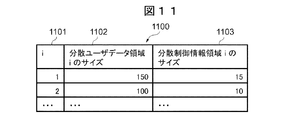
図11に、分散ユーザデータ領域と分散制御情報領域のサイズを管理するための管理テーブル1100の構成を示す。   FIG. 11 shows the configuration of a management table 1100 for managing the sizes of the distributed user data area and the distributed control information area.

図11において、管理テーブル1100は、主メモリ123またはキャッシュメモリ124に格納されるテーブルであって、iフィールド1101と、分散ユーザデータ領域iのサイズフィールド1102と、分散制御情報領域iのサイズフィールド1103から構成される。iフィールド1101の各エントリには、分散ユーザデータ領域と分散制御情報領域を識別するための番号が格納される。分散ユーザデータ領域iサイズフィールド1102の各エントリには、例えば、分散ユーザデータ領域1001、1002のサイズが数値(150、100)で格納される。分散制御情報領域iのサイズフィールド1103の各エントリには、例えば、分散制御情報領域1011、1012のサイズが数値(15、10)で格納される。   In FIG. 11, a management table 1100 is a table stored in the main memory 123 or the cache memory 124, and includes an i field 1101, a size field 1102 of the distributed user data area i, and a size field 1103 of the distributed control information area i. Consists of Each entry of the i field 1101 stores a number for identifying the distributed user data area and the distributed control information area. In each entry of the distributed user data area i size field 1102, for example, the sizes of the distributed user data areas 1001 and 1002 are stored as numerical values (150, 100). In each entry of the size field 1103 of the distributed control information area i, for example, the sizes of the distributed control information areas 1011 and 1012 are stored as numerical values (15, 10).

分散ユーザデータ領域と分散制御情報領域のサイズに関する情報は、前述した3390形式のボリュームの容量拡張を実施する度に、管理テーブル1100のエントリに追加される。   Information regarding the sizes of the distributed user data area and the distributed control information area is added to the entry of the management table 1100 every time the capacity of the 3390-format volume is expanded.

図11における管理テーブル1100の各エントリにおいて、分散ユーザデータ領域のサイズと、分散制御情報領域のサイズと、は一定ではない。但し、管理テーブル1100の各エントリにおいて、分散ユーザデータ領域のサイズと分散制御情報領域のサイズとの比は一定である。   In each entry of the management table 1100 in FIG. 11, the size of the distributed user data area and the size of the distributed control information area are not constant. However, in each entry of the management table 1100, the ratio between the size of the distributed user data area and the size of the distributed control information area is constant.

図12に、分散ユーザデータ領域と分散制御情報領域のアドレスを管理するための管理テーブル1200を示す。   FIG. 12 shows a management table 1200 for managing the addresses of the distributed user data area and the distributed control information area.

図12において、管理テーブル1200は、iフィールド1201と、分散ユーザデータ領域iの先頭アドレスフィールド(3390形式)1202と、分散ユーザデータ領域iの先頭アドレスフィールド(実記憶領域上のデータ配置)1203、分散制御情報領域iの先頭アドレスフィールド1204と、分散制御情報領域iの先頭アドレスフィールド(実記憶領域上のデータ配置)1205から構成され、例えば、主メモリ123またはキャッシュメモリ124に格納される。   12, the management table 1200 includes an i field 1201, a head address field (3390 format) 1202 of the distributed user data area i, a head address field (data arrangement on the real storage area) 1203 of the distributed user data area i, The head address field 1204 of the distributed control information area i and the head address field (data arrangement on the real storage area) 1205 of the distributed control information area i are stored in the main memory 123 or the cache memory 124, for example.

iフィールド1201の各エントリには、分散ユーザデータ領域と分散制御情報領域を識別するための番号が格納される。分散ユーザデータ領域iの先頭アドレスフィールド1202の各エントリには、例えば、記憶領域910における分散ユーザデータ領域1001、1002の先頭アドレスが、数値(0、150)で格納される。分散ユーザデータ領域iの先頭アドレスフィールド1203の各エントリには、例えば、実記憶領域920における分散ユーザデータ領域1001、1002の先頭アドレスが、数値(0、165)で格納される。   Each entry of the i field 1201 stores a number for identifying the distributed user data area and the distributed control information area. In each entry of the start address field 1202 of the distributed user data area i, for example, the start addresses of the distributed user data areas 1001 and 1002 in the storage area 910 are stored as numerical values (0, 150). In each entry of the start address field 1203 of the distributed user data area i, for example, the start addresses of the distributed user data areas 1001 and 1002 in the real storage area 920 are stored as numerical values (0, 165).

分散制御情報領域iの先頭アドレスフィールド1204の各エントリには、例えば、記憶領域910における分散制御情報領域1011、1012の先頭アドレスが、数値(250、265)で格納される。分散制御情報領域iの先頭アドレスフィールド1205の各エントリには、例えば、実記憶領域920における分散制御情報領域1011、1012の先頭アドレスが、数値(150、165)で格納される。   In each entry of the start address field 1204 of the distribution control information area i, for example, the start addresses of the distribution control information areas 1011 and 1012 in the storage area 910 are stored as numerical values (250 and 265). In each entry of the start address field 1205 of the distributed control information area i, for example, the start address of the distributed control information areas 1011 and 1012 in the real storage area 920 is stored as a numerical value (150, 165).

分散ユーザデータ領域と分散制御情報領域の先頭アドレスに関する情報は、前述した3390形式のボリュームの容量拡張を実施する度に、管理テーブル1200のエントリに追加される。   Information regarding the start address of the distributed user data area and the distributed control information area is added to the entry of the management table 1200 each time the capacity of the 3390-format volume is expanded.

次に、前述した3390形式のデータ配置上のトラック番号のデータ部325を指すアドレスから、実記憶領域920上のデータ配置のトラック番号のデータ部325を指すアドレスを計算する処理を図13のフローチャートに従って説明する。   Next, the process of calculating the address indicating the data portion 325 of the track number of the data arrangement on the real storage area 920 from the address indicating the data portion 325 of the track number on the data arrangement of the 3390 format described above is a flowchart of FIG. It explains according to.

マイクロプログラム231内のアドレス変換部254は、まず、iを0とし(S11)、管理テーブル1100、1200を参照して、3390形式上の0番目(i番目)の分散ユーザデータ領域の先頭アドレスとサイズに関する情報を取得し(S12)、次に、例えば、記憶領域910における分散ユーザデータ領域1002におけるアドレス1021が、0番目(i番目)の分散ユーザデータ領域に含まれるか否かを判定し(S13)、このステップS13で否定の判定結果を得たときには、iをインクリメント(例えば、iを1に)し(S14)、ステップS13で肯定の判定結果が得られるまで、ステップS12〜S14の処理を繰り返す。   The address conversion unit 254 in the microprogram 231 first sets i to 0 (S11), refers to the management tables 1100 and 1200, and sets the start address of the 0th (i-th) distributed user data area in the 3390 format. Information on the size is acquired (S12), and then, for example, it is determined whether or not the address 1021 in the distributed user data area 1002 in the storage area 910 is included in the 0th (i-th) distributed user data area ( S13) When a negative determination result is obtained in step S13, i is incremented (for example, i is set to 1) (S14), and the processes of steps S12 to S14 are performed until a positive determination result is obtained in step S13. repeat.

ステップS13で肯定の判定結果が得られた場合、例えば、記憶領域910における分散ユーザデータ領域1002におけるアドレス1021は、2番目の分散ユーザデータ領域1002に含まれる場合、アドレス変換部254は、管理テーブル1100に格納された各分散ユーザデータ領域と分散制御領域のサイズと、管理テーブル1200に格納された各分散ユーザデータ領域と分散制御情報領域のアドレスと、3390形式のデータ配置上でトラック番号のデータ部325を指すアドレス1021と、を基に、アドレス1021が含まれる分散ユーザデータ領域1002の番号(2)と、分散ユーザデータ領域1002の先頭アドレスからアドレス1021までのオフセットアドレスと、を計算する(S15)。   When a positive determination result is obtained in step S13, for example, when the address 1021 in the distributed user data area 1002 in the storage area 910 is included in the second distributed user data area 1002, the address conversion unit 254 displays the management table. The size of each distributed user data area and distributed control area stored in 1100, the address of each distributed user data area and distributed control information area stored in the management table 1200, and the track number data on the 3390 format data arrangement Based on the address 1021 pointing to the section 325, the number (2) of the distributed user data area 1002 including the address 1021 and the offset address from the head address of the distributed user data area 1002 to the address 1021 are calculated ( S15).

次に、アドレス変換部254は、分散ユーザデータ領域と分散制御情報領域のアドレスと、分散ユーザデータ領域1002の番号(2)と、を基に、管理テーブル1200を参照して、分散ユーザデータ領域1002の番号(2)が表す分散ユーザデータ領域1002の先頭アドレス(実記憶領域920における分散ユーザデータ領域1002の先頭アドレス)を取得する(S16)。   Next, the address conversion unit 254 refers to the management table 1200 based on the addresses of the distributed user data area and the distributed control information area, and the number (2) of the distributed user data area 1002, and distributes the user data area. The head address of the distributed user data area 1002 indicated by the number (2) 1002 (the head address of the distributed user data area 1002 in the real storage area 920) is acquired (S16).

最後に、アドレス変換部254は、前述した実記憶領域920における分散ユーザデータ領域1002の先頭アドレスと、記憶領域910における先頭アドレスからアドレス1021までのオフセットアドレスと、を基に、実記憶領域920上のトラック番号のデータ部325を指すアドレス1022を計算する(S17)。   Finally, the address conversion unit 254 stores the data in the real storage area 920 based on the start address of the distributed user data area 1002 in the real storage area 920 and the offset address from the start address in the storage area 910 to the address 1021. The address 1022 indicating the track number data portion 325 is calculated (S17).

上記処理を実行することで、アドレス変換部254は、3390形式のデータ配置上のトラック番号のデータ部325を指すアドレス1021を、実記憶領域920上のデータ配置のトラック番号のデータ部325を指すアドレス1022に変換することができる。   By executing the above processing, the address conversion unit 254 points the address 1021 indicating the track number data portion 325 on the data arrangement in the 3390 format to the track number data portion 325 on the real storage area 920. The address 1022 can be converted.

また、アドレス変換部254は、アドレス1021をアドレス1022に変換する処理と同様の処理を実行することで、前述した3390形式のデータ配置上のトラック番号1031の制御情報部326を指すアドレスから、実記憶領域920上のトラック番号の制御情報部326を指すアドレスを計算することができる。   In addition, the address conversion unit 254 executes a process similar to the process of converting the address 1021 into the address 1022, so that the address indicating the control information unit 326 of the track number 1031 on the data arrangement in the 3390 format described above is actually executed. An address indicating the control information portion 326 of the track number on the storage area 920 can be calculated.

本実施例によれば、トラックの制御情報部326をスキップして、ディスクのヘッドをデータ部325に位置付ける処理のオーバヘッドを減らせるので、ストレージコントローラ131は、トラックの制御情報部326を参照するときよりも、ディスクに対するリードアクセスまたはライトアクセスの性能を向上させることができる。   According to the present embodiment, the track control information unit 326 can be skipped to reduce the overhead of the process of positioning the disk head in the data unit 325, so that the storage controller 131 refers to the track control information unit 326. As a result, the performance of read access or write access to the disk can be improved.

また、本実施例によれば、3390形式の記憶領域910の容量が拡張された場合でも、3390形式のデータ配置上のトラック番号のデータ部325を指すアドレス1021を、実記憶領域920上のデータ配置のトラック番号のデータ部325を指すアドレス1022に変換することができるとともに、3390形式のデータ配置上のトラック番号の制御情報部326を指すアドレスを、実記憶領域920上のトラック番号の制御情報部326を指すアドレスに変換することができる。   Further, according to the present embodiment, even when the capacity of the storage area 910 in the 3390 format is expanded, the address 1021 indicating the data part 325 of the track number on the data arrangement in the 3390 format is stored in the data on the real storage area 920. The address indicating the track number data portion 325 of the arrangement can be converted into the address 1022 and the address indicating the track number control information portion 326 on the data arrangement in the 3390 format is used as the control information of the track number on the real storage area 920. It can be converted to an address that points to part 326.

このため、コマンド制御部251は、3390形式のデータ配置である、LDEV322の容量拡張後も、アドレス変換部254のアドレス変換で得られたアドレスを用いることで、実記憶領域上のデータ配置に従うボリュームを、3390形式のボリュームとしてアクセスすることができる。   For this reason, the command control unit 251 uses the address obtained by the address conversion of the address conversion unit 254 even after the capacity expansion of the LDEV 322, which is a data arrangement in the 3390 format, so that the volume according to the data arrangement in the real storage area Can be accessed as a 3390 format volume.

本実施例は、一つの分散ユーザデータ領域(第2データ領域)と一つの分散制御情報領域を一つのシリンダグループ(CG)として、シリンダグループを複数グループ有し、各シリンダグループを容量拡張単位の記憶領域として管理し、記憶領域として、複数のシリンダグループが並ぶデータ配置(第2データ配置)を採用するボリュームを第2ボリューム形式(以下、3390−A形式と称することもある。)のボリューム(LDEV322)として管理し、3390形式のボリュームに関するアドレスを3390−A形式のボリュームに関するアドレスに変換するものである。   This embodiment has one distributed user data area (second data area) and one distributed control information area as one cylinder group (CG), and has a plurality of cylinder groups. Each cylinder group is a capacity expansion unit. A volume that is managed as a storage area and uses a data arrangement (second data arrangement) in which a plurality of cylinder groups are arranged as a storage area is a volume of a second volume format (hereinafter also referred to as a 3390-A format). LDEV 322), and addresses related to 3390 format volumes are converted to addresses related to 3390-A format volumes.

<3390‐A形式のLDEV322内のデータ配置>   <Data Arrangement in LDEV 322 in 3390-A Format>

図14に、3390‐A形式のLDEV322内のデータ配置を示す。   FIG. 14 shows the data arrangement in the LDEV 322 in the 3390-A format.

図14において、LDEV322の実記憶領域930は、分散ユーザデータ領域1401と、分散ユーザデータ領域1401に連なる分散制御情報領域1411を含むシリンダグループ(CG)1421と、分散ユーザデータ領域1402と、分散ユーザデータ領域1402に連なる分散制御情報領域1412を含むシリンダグループ(CG)1422から構成される。各分散ユーザデータ領域1401、1402は、それぞれ同一のサイズで構成され、各分散制御情報領域1411、1412もそれぞれ同一のサイズで構成される。即ち、各シリンダグループ(CG)1411、1422はそれぞれ同一のサイズで構成され、シリンダグループの容量が、容量拡張の単位になっている。   14, the real storage area 930 of the LDEV 322 includes a distributed user data area 1401, a cylinder group (CG) 1421 including a distributed control information area 1411 connected to the distributed user data area 1401, a distributed user data area 1402, and a distributed user. A cylinder group (CG) 1422 including a distributed control information area 1412 connected to the data area 1402 is configured. Each of the distributed user data areas 1401 and 1402 is configured with the same size, and each of the distributed control information areas 1411 and 1412 is also configured with the same size. That is, the cylinder groups (CG) 1411 and 1422 are configured with the same size, and the capacity of the cylinder group is a unit of capacity expansion.

この際、ストレージコントローラ131は、例えば、シリンダグループ(CG)1421を構成する記憶領域であって、分散ユーザデータ領域(第2データ領域)1401に連続して分散制御情報領域(第2制御情報領域)1411が配置された実記憶領域930のデータ配置を第2データ配置とする第2ボリューム形式(以下、3390−A形式と称することもある。)でLDEV322を管理する。   At this time, the storage controller 131 is, for example, a storage area constituting the cylinder group (CG) 1421, and is continuously distributed to the distributed user data area (second data area) 1401 (second control information area (second control information area)). ) The LDEV 322 is managed in a second volume format (hereinafter also referred to as 3390-A format) in which the data allocation of the real storage area 930 in which 1411 is allocated is the second data allocation.

3390‐A形式のLDEV322を構成する一つまたは複数のCG1421は、CG番号によって参照されてもよい。また、当該LDEV322を構成する一つまたは複数の分散ユーザデータ領域1401は、後述する分散ユーザデータ領域の番号によって参照されてもよい。また、当該LDEV322を構成する一つまたは複数の分散制御情報領域1411は、後述する分散制御情報領域の番号によって参照されてもよい。   One or a plurality of CGs 1421 constituting the LDEV 322 in the 3390-A format may be referred to by a CG number. Further, one or a plurality of distributed user data areas 1401 constituting the LDEV 322 may be referred to by a distributed user data area number described later. Further, one or a plurality of distribution control information areas 1411 constituting the LDEV 322 may be referred to by the number of the distribution control information area described later.

図15に、シリンダグループ1421内の構成を示す。   FIG. 15 shows the configuration within the cylinder group 1421.

シリンダグループ(CG)1421は、分散ユーザデータ領域1401と分散制御情報領域1411から構成される。分散ユーザデータ領域1401は、複数(D個)のデータ部(トラック1〜Dに対応した1または複数のレコードを含む)325を格納する第2データ領域として構成される。   The cylinder group (CG) 1421 includes a distributed user data area 1401 and a distributed control information area 1411. The distributed user data area 1401 is configured as a second data area for storing a plurality (D) of data portions (including one or a plurality of records corresponding to tracks 1 to D) 325.

分散制御情報領域1411は、分散ユーザデータ領域1401に連なり、かつ分散ユーザデータ領域1401に格納された各データ部325をそれぞれアクセスするための制御情報で構成された複数(D個)の制御情報部326と、各データ部325の各トラックにレコードが存在するか否かを示すレコード有無情報で構成された複数(D個)のレコード有無情報部327と、LDEV322をストレージコントローラ131が管理するためのストレージ機能管理情報328と、ストレージコントローラ131がシリンダグループを拡張するためのモードか否かを判定するための拡張モード判定情報329を格納する第2制御情報領域として構成される。   The distributed control information area 1411 is connected to the distributed user data area 1401 and includes a plurality (D) of control information sections configured by control information for accessing each data section 325 stored in the distributed user data area 1401. 326, a plurality of (D) record presence / absence information units 327 configured by record presence / absence information indicating whether or not a record exists in each track of each data unit 325, and the storage controller 131 for managing the LDEV 322 It is configured as a second control information area for storing storage function management information 328 and expansion mode determination information 329 for determining whether or not the storage controller 131 is in a mode for expanding a cylinder group.

この際、マイクロプログラム231は、各トラック内のデータ部325をトラック番号により識別し、各トラック内の制御情報部326をトラック番号により識別する。   At this time, the microprogram 231 identifies the data portion 325 in each track by the track number, and identifies the control information portion 326 in each track by the track number.

各制御情報部326と各レコード有無情報部327は、例えば、ビットマップで構成することもできる。レコードは、各トラックのデータ部325に一つまたは複数保存される。このレコードは、例えば、MFホスト計算機102からのライトデータなどである。   Each control information unit 326 and each record presence / absence information unit 327 can be configured by, for example, a bitmap. One or more records are stored in the data portion 325 of each track. This record is, for example, write data from the MF host computer 102.

また、各シリンダグループ1421、1422において、分散ユーザデータ領域1401、1402内のトラックのデータ部325の数(D個)と、分散制御情報領域1411、1412内のトラックの制御情報部326の数(D個)及び分散制御情報領域1411、1412内のトラックのレコード有無情報部327の数(D個)は等しい。   In each cylinder group 1421 and 1422, the number of track data portions 325 (D) in the distributed user data areas 1401 and 1402 and the number of track control information portions 326 in the distributed control information areas 1411 and 1412 ( D) and the number (D) of record presence / absence information portions 327 of the tracks in the distribution control information areas 1411 and 1412 are equal.

図16に、3390形式のLDEV322上のアドレスと3390‐A形式のLDEV322上のアドレスの対応を示す。   FIG. 16 shows the correspondence between addresses on the L390 322 in the 3390 format and addresses on the LDEV 322 in the 3390-A format.

図16において、3390形式のLDEV322の記憶領域910は、分散ユーザデータ領域1401、1402、1403と、分散制御情報領域1411、1412、1413から構成され、3390−A形式のLDEVの実記憶領域930は、分散ユーザデータ領域1401と分散制御情報領域1411を含むシリンダグループ1421と、分散ユーザデータ領域1402と分散制御情報領域1412を含むシリンダグループ1422と、分散ユーザデータ領域1403と分散制御情報領域1413を含むシリンダグループ1423から構成される。   In FIG. 16, the storage area 910 of the 3390 format LDEV 322 is composed of distributed user data areas 1401, 1402, and 1403, and distributed control information areas 1411, 1412, and 1413, and the actual storage area 930 of the 3390-A format LDEV is A cylinder group 1421 including a distributed user data area 1401 and a distributed control information area 1411; a cylinder group 1422 including a distributed user data area 1402 and a distributed control information area 1412; a distributed user data area 1403 and a distributed control information area 1413. It is composed of a cylinder group 1423.

3390形式のボリュームのデータ配置は、分散ユーザデータ領域1401、分散ユーザデータ領域1402、分散ユーザデータ領域1403、分散制御情報領域1411、分散制御情報領域1412、分散制御情報領域1413の順番であり、3390‐A形式のボリュームのデータ配置は、シリンダグループ1421、シリンダグループ1422、シリンダグループ1423の順番である。   The data arrangement of the volume in the 3390 format is the order of the distributed user data area 1401, the distributed user data area 1402, the distributed user data area 1403, the distributed control information area 1411, the distributed control information area 1412, and the distributed control information area 1413. The data arrangement of the volume in the A format is the order of the cylinder group 1421, the cylinder group 1422, and the cylinder group 1423.

3390形式のボリュームのデータ配置と3390‐A形式のボリュームのデータ配置が異なる構成を採用すると、3390形式のデータ配置である記憶領域910におけるトラック番号のデータ部325を指すアドレスと、3390−A形式のデータ配置である実記憶領域930におけるトラック番号のデータ部325を指すアドレスは、トラック番号が同一であっても、各分散ユーザデータ領域や各分散制御情報領域におけるアドレスの値が異なる。このため、マイクロプログラム231内のアドレス変換部254は、例えば、記憶領域910の分散ユーザデータ領域1403におけるトラック番号のデータ部325を指すアドレス1031を、実記憶領域930におけるトラック番号のデータ部325を指すアドレス1032に変換するためのアドレス変換を実行する。   If a configuration in which the data arrangement of the 3390-format volume and the data arrangement of the 3390-A-format volume are different is adopted, an address indicating the data part 325 of the track number in the storage area 910 which is the data arrangement of the 3390 format, and the 3390-A format The address indicating the data part 325 of the track number in the real storage area 930 having the data arrangement is different in the address value in each distributed user data area and each distributed control information area even if the track number is the same. Therefore, for example, the address conversion unit 254 in the microprogram 231 uses the address 1031 indicating the track number data unit 325 in the distributed user data area 1403 in the storage area 910 and the track number data section 325 in the real storage area 930. Address conversion for converting to the address 1032 indicated is executed.

同様に、マイクロプログラム231内のアドレス変換部254は、3390形式のデータ配置上である記憶領域910におけるトラック番号の制御情報部326を指すアドレスを、3390−A形式のデータ配置である実記憶領域930におけるトラック番号の制御情報部326を指すアドレスに変換するためのアドレス変換を行う。   Similarly, the address conversion unit 254 in the microprogram 231 uses an address indicating the track number control information unit 326 in the storage area 910 on the 3390-format data arrangement as the real storage area on the 3390-A format data arrangement. Address conversion is performed for conversion to an address indicating the control information portion 326 of the track number in 930.

コマンド制御部251は、アドレス変換部254のアドレス変換により得られたアドレスを用いることで、実記憶領域上は3390‐A形式のデータ配置に従うLDEV322を、3390形式のLDEV322としてアクセスすることができる。即ち、コマンド制御部251は、3390形式のデータ配置のLDEV322にアクセスしても、3390形式のデータ配置のLDEV322にアドレスが、アドレス変換部254のアドレス変換によって、3390‐A形式のデータ配置に従うLDEV322のアドレスが変換されるので、結果として、実記憶領域上のデータ部325をアクセスすることができる。   The command control unit 251 can access the LDEV 322 conforming to the data arrangement in the 3390-A format on the real storage area as the LDEV 322 in the 3390 format by using the address obtained by the address conversion of the address conversion unit 254. That is, even if the command control unit 251 accesses the LDEV 322 having the data arrangement in the 3390 format, the address in the LDEV 322 having the data arrangement in the 3390 format is converted to the LDEV 322 according to the data arrangement in the 3390-A format by the address conversion of the address conversion unit 254 As a result, the data part 325 in the real storage area can be accessed.

<3390‐A形式のLDEV322の容量拡張>   <Capacity Expansion of 3390-A Format LDEV322>

図17に、分散ユーザデータ領域と分散制御情報領域のサイズを管理するための管理テーブル1700の構成を示す。   FIG. 17 shows the configuration of a management table 1700 for managing the sizes of the distributed user data area and the distributed control information area.

図17において、管理テーブル1700は、3390‐A形式のLDEV322を管理するためのテーブルとして、分散ユーザデータ領域長フィールド1701と、分散制御情報領域長フィールド1702から構成され、例えば、主メモリ123またはキャッシュメモリ124に格納される。分散ユーザデータ領域長フィールド1701のエントリには、各分散ユーザデータ領域共通の長さを示す情報が数値で格納される。分散制御情報領域長フィールド1702のエントリには、各分散制御情報領域共通の長さを示す情報が数値で格納される。   In FIG. 17, a management table 1700 is a table for managing a 3390-A format LDEV 322, and is composed of a distributed user data area length field 1701 and a distributed control information area length field 1702, for example, main memory 123 or cache Stored in the memory 124. In the entry of the distributed user data area length field 1701, information indicating the length common to each distributed user data area is stored as a numerical value. In the entry of the distributed control information area length field 1702, information indicating the common length of each distributed control information area is stored as a numerical value.

図18に、分散ユーザデータ領域と分散制御情報領域のアドレスを管理するための管理テーブル1800の構成を示す。   FIG. 18 shows the configuration of a management table 1800 for managing the addresses of the distributed user data area and the distributed control information area.

図18において、管理テーブル1800は、iフィールド1801と、分散ユーザデータ領域iの先頭アドレスフィールド(3390形式)1802と、分散ユーザデータ領域iの先頭アドレスフィールド(3390−A形式のデータ配置)1803、分散制御情報領域iの先頭アドレスフィールド(3390形式)1804と、分散制御情報領域iの先頭アドレスフィールド(3390−A形式のデータ配置)1805から構成され、例えば、主メモリ123またはキャッシュメモリ124に格納される。   In FIG. 18, the management table 1800 includes an i field 1801, a head address field (3390 format) 1802 of the distributed user data area i, a head address field (3390-A format data arrangement) 1803 of the distributed user data area i, It consists of a head address field (3390 format) 1804 of the distributed control information area i and a head address field (data arrangement of 3390-A format) 1805 of the distributed control information area i, and is stored in the main memory 123 or the cache memory 124, for example. Is done.

iフィールド1201の各エントリには、分散ユーザデータ領域と分散制御情報領域を識別するための番号が格納される。分散ユーザデータ領域iの先頭アドレスフィールド1802の各エントリには、例えば、記憶領域910における分散ユーザデータ領域1401、1402の先頭アドレスが数値(0、100)で格納される。分散ユーザデータ領域iの先頭アドレスフィールド1803の各エントリには、例えば、実記憶領域930における分散ユーザデータ領域1401、1402の先頭アドレスが数値(0、150)で格納される。   Each entry of the i field 1201 stores a number for identifying the distributed user data area and the distributed control information area. In each entry of the start address field 1802 of the distributed user data area i, for example, the start addresses of the distributed user data areas 1401 and 1402 in the storage area 910 are stored as numerical values (0, 100). In each entry of the start address field 1803 of the distributed user data area i, for example, the start addresses of the distributed user data areas 1401 and 1402 in the real storage area 930 are stored as numerical values (0, 150).

分散制御情報領域iの先頭アドレスフィールド1804の各エントリには、例えば、記憶領域910における分散制御情報領域1411、1412の先頭アドレスが数値(500、550)で格納される。分散制御情報領域iの先頭アドレスフィールド1805の各エントリには、例えば、実記憶領域930における分散制御情報領域1411、1412の先頭アドレスが数値(100、250)で格納される。   In each entry of the start address field 1804 of the distributed control information area i, for example, the start addresses of the distributed control information areas 1411 and 1412 in the storage area 910 are stored as numerical values (500, 550). In each entry of the start address field 1805 of the distribution control information area i, for example, the start addresses of the distribution control information areas 1411 and 1412 in the real storage area 930 are stored as numerical values (100, 250).

各分散ユーザデータ領域と各分散制御情報領域の先頭アドレスに関する情報は、3390形式のボリュームの容量拡張を実施する度に、管理テーブル1800のエントリに追加される。   Information regarding the start address of each distributed user data area and each distributed control information area is added to the entry of the management table 1800 each time the capacity of a 3390-format volume is expanded.

次に、3390‐A形式のLDEV322の容量拡張処理を図19のフローチャートに従って説明する。   Next, the capacity expansion processing of the 3390-A format LDEV 322 will be described with reference to the flowchart of FIG.

管理ホスト計算機103が、管理ホストI/F127を介して、構成制御部253にLDEV322の容量拡張指示を行うと、構成制御部253は、管理テーブル1700を参照し、分散ユーザデータ領域のサイズ(100)と分散制御情報領域のサイズ(50)を取得する(S21)。   When the management host computer 103 instructs the configuration control unit 253 to expand the capacity of the LDEV 322 via the management host I / F 127, the configuration control unit 253 refers to the management table 1700, and determines the size of the distributed user data area (100 ) And the size (50) of the distributed control information area are acquired (S21).

次に、構成制御部253は、管理ホスト103において指定された拡張容量が、取得した分散ユーザデータ領域のサイズ(100)の整数倍であるかどうかをチェックする(S22)。   Next, the configuration control unit 253 checks whether or not the extended capacity designated in the management host 103 is an integer multiple of the acquired size (100) of the distributed user data area (S22).

この管理画面で指定される拡張容量が、分散ユーザデータ領域のサイズ(100)の整数倍でない場合、構成制御部253は、このLDEV322の容量拡張は失敗したことを、管理ホストI/F127を介して、管理ホスト計算機103に通知して、容量拡張処理を終了する。   If the expansion capacity specified on this management screen is not an integral multiple of the size (100) of the distributed user data area, the configuration control unit 253 indicates that the capacity expansion of this LDEV 322 has failed via the management host I / F 127. Thus, the management host computer 103 is notified and the capacity expansion process is terminated.

一方、拡張容量が、分散ユーザデータ領域のサイズ(100)の整数倍である場合、構成制御部253は、拡張容量を分散ユーザデータ領域のサイズ(100)で割った商を、拡張シリンダグループ数として、主メモリ123に保存する。   On the other hand, when the expansion capacity is an integral multiple of the size (100) of the distributed user data area, the configuration control unit 253 divides the quotient obtained by dividing the expansion capacity by the size (100) of the distributed user data area. Is stored in the main memory 123.

次に、構成制御部253は、前述した拡張シリンダグループ数の数だけ、シリンダグループ(CG)を保存できる記憶領域(以下、拡張CG領域と称することもある。)を確保する(S23)。この場合、容量拡張において、確保する拡張CG領域のサイズは、拡張前領域の容量単位であるCGのサイズの整数倍である。   Next, the configuration control unit 253 secures a storage area (hereinafter also referred to as an extended CG area) in which cylinder groups (CG) can be stored as many as the number of extended cylinder groups described above (S23). In this case, in the capacity expansion, the size of the extended CG area to be secured is an integral multiple of the size of the CG that is the capacity unit of the area before expansion.

この後、構成制御部253は、拡張する容量分のCG領域確保に成功したか否かを判定し(S24)、拡張CG領域の確保に失敗した場合、管理ホストI/F127を介して、LDEV322の容量拡張に失敗したことを管理ホスト計算機103に通知して、容量拡張処理を終了する。   Thereafter, the configuration control unit 253 determines whether or not the CG area for the capacity to be expanded has been successfully secured (S24), and when securing the extended CG area fails, the LDEV 322 is transmitted via the management host I / F 127. The management host computer 103 is notified that the capacity expansion has failed, and the capacity expansion processing is terminated.

拡張CG領域の確保に成功した場合、構成制御部253は、ボリューム管理情報内のボリューム容量に変更後のサイズを設定し(S25)、ホストI/F121を介して、MFホスト計算機102に対して容量変更が行われたことを通知するとともに、容量拡張が成功したことを通知し、このルーチンでの処理を終了する。   If the expansion CG area is successfully secured, the configuration control unit 253 sets the changed size to the volume capacity in the volume management information (S25), and sends the MF host computer 102 via the host I / F 121. Notifying that the capacity change has been performed and notifying that the capacity expansion has succeeded, the processing in this routine is terminated.

なお、拡張CG領域上に存在する、一つまたは複数の分散制御情報領域は予め初期化していてもいいし、していなくても良い。   One or a plurality of distributed control information areas existing on the extended CG area may or may not be initialized in advance.

また、容量拡張指示は、前述したMFホスト計算機102およびストレージ装置101からなるストレージシステムがオンライン中に行ってもよい。   The capacity expansion instruction may be issued while the storage system including the MF host computer 102 and the storage apparatus 101 described above is online.

図20に、容量拡張後における3390形式のLDEV322上のアドレスと3390‐A形式のLDEV322上のアドレスの対応を示す。   FIG. 20 shows the correspondence between the addresses on the 3390-format LDEV 322 and the addresses on the 3390-A-format LDEV 322 after capacity expansion.

マイクロプログラム231内の構成制御部253が、管理ホストI/F127を介して、管理ホスト計算機103から容量拡張指示を受領すると、構成制御部253は、3390形式のLDEV322上のデータ配置として、分散ユーザデータ領域1403の後に、分散ユーザデータ領域1404、1405を配置し、3390‐A形式のLDEV322上のデータ配置として、シリンダグループ1423の後ろに、新たに確保した実記憶領域として、拡張シリンダグループ1424、1415を配置する。   When the configuration control unit 253 in the microprogram 231 receives a capacity expansion instruction from the management host computer 103 via the management host I / F 127, the configuration control unit 253 uses the distributed user as a data arrangement on the 3390 format LDEV 322. After the data area 1403, distributed user data areas 1404 and 1405 are arranged. As a data arrangement on the LDEV 322 in the 3390-A format, an expansion cylinder group 1424, a newly allocated real storage area behind the cylinder group 1423, 1415 is arranged.

図20において、3390形式のLDEV322の記憶領域910は、分散ユーザデータ領域1401、1402、1403、1404、1405と、分散制御情報領域1411、1412、1413、1414、1415から構成され、3390−A形式のLDEVの実記憶領域930は、分散ユーザデータ領域1401と分散制御情報領域1411を含むシリンダグループ1421と、分散ユーザデータ領域1402と分散制御情報領域1412を含むシリンダグループ1422と、分散ユーザデータ領域1403と分散制御情報領域1413を含むシリンダグループ1423と、分散ユーザデータ領域1404と分散制御情報領域1414を含む拡張シリンダグループ1424と、分散ユーザデータ領域1405と分散制御情報領域1415を含む拡張シリンダグループ1425から構成される。   In FIG. 20, the storage area 910 of the L390 322 in the 3390 format is composed of distributed user data areas 1401, 1402, 1403, 1404, 1405 and distributed control information areas 1411, 1412, 1413, 1414, 1415, and the 3390-A format. The LDEV real storage area 930 includes a cylinder group 1421 including a distributed user data area 1401 and a distributed control information area 1411, a cylinder group 1422 including a distributed user data area 1402 and a distributed control information area 1412, and a distributed user data area 1403. And a cylinder group 1423 including a distributed control information area 1413, an extended cylinder group 1424 including a distributed user data area 1404 and a distributed control information area 1414, a distributed user data area 1405 and a distributed control information area 1 Composed of extended cylinder group 1425 containing 15.

3390形式のボリュームのデータ配置は、分散ユーザデータ領域1401、分散ユーザデータ領域1402、分散ユーザデータ領域1403、分散ユーザデータ領域1404、分散ユーザデータ領域1405、分散制御情報領域1411、分散制御情報領域1412、分散制御情報領域1413、分散制御情報領域1414、分散制御情報領域1415の順番であり、実記憶領域となる3390‐A形式のボリュームのデータ配置は、シリンダグループ(CG)1421、シリンダグループ1422、シリンダグループ1423、拡張シリンダグループ1424、拡張シリンダグループ1425の順番である。   The data arrangement of the 3390 format volume is as follows: distributed user data area 1401, distributed user data area 1402, distributed user data area 1403, distributed user data area 1404, distributed user data area 1405, distributed control information area 1411, distributed control information area 1412. , Distributed control information area 1413, distributed control information area 1414, distributed control information area 1415 in this order, and the data arrangement of the 3390-A format volume that is the real storage area is as follows: cylinder group (CG) 1421, cylinder group 1422, The cylinder group 1423, the extended cylinder group 1424, and the extended cylinder group 1425 are in this order.

3390形式のボリュームのデータ配置と3390‐A形式のボリュームのデータ配置が異なる構成を採用すると、3390形式のデータ配置である記憶領域910におけるトラック番号のデータ部325を指すアドレスと、3390−A形式のデータ配置である実記憶領域930におけるトラック番号のデータ部325を指すアドレスは、トラック番号が同一であっても、各分散ユーザデータ領域や各分散制御情報領域におけるアドレスの値が異なる。このため、マイクロプログラム231内のアドレス変換部254は、例えば、記憶領域910の分散ユーザデータ領域1405におけるトラック番号のデータ部325を指すアドレス1051を、実記憶領域930におけるトラック番号のデータ部325を指すアドレス1052に変換するためのアドレス変換を実行する。   If a configuration in which the data arrangement of the 3390-format volume and the data arrangement of the 3390-A-format volume are different is adopted, an address indicating the data part 325 of the track number in the storage area 910 which is the data arrangement of the 3390 format, and the 3390-A format The address indicating the data part 325 of the track number in the real storage area 930 having the data arrangement is different in the address value in each distributed user data area and each distributed control information area even if the track number is the same. Therefore, for example, the address conversion unit 254 in the microprogram 231 uses the address 1051 indicating the track number data unit 325 in the distributed user data area 1405 of the storage area 910 and the track number data part 325 in the real storage area 930. Address conversion is performed to convert the address 1052 to be indicated.

同様に、マイクロプログラム231内のアドレス変換部254は、3390形式のデータ配置上である記憶領域910におけるトラック番号の制御情報部326を指すアドレスを、3390−A形式のデータ配置である実記憶領域930におけるトラック番号の制御情報部326を指すアドレスに変換するためのアドレス変換を行う。   Similarly, the address conversion unit 254 in the microprogram 231 uses an address indicating the track number control information unit 326 in the storage area 910 on the 3390-format data arrangement as the real storage area on the 3390-A format data arrangement. Address conversion is performed for conversion to an address indicating the control information portion 326 of the track number in 930.

コマンド制御部251は、3390‐A形式のLDEV322の容量拡張後も、アドレス変換部254のアドレス変換により得られたアドレスを用いることで、実記憶領域上は3390‐A形式のデータ配置に従うLDEV322を、3390形式のLDEV322としてアクセスすることができる。   The command control unit 251 uses the address obtained by the address conversion of the address conversion unit 254 even after the capacity expansion of the 3390-A format LDEV 322, so that the LDEV 322 conforming to the data arrangement of the 3390-A format is used on the real storage area. , 3390 format LDEV 322 can be accessed.

次に、3390形式のボリューム上のトラック番号のデータ部を指すアドレス1051から、3390‐A形式のボリューム上のトラック番号のデータ部を指すアドレス1052を計算する処理を図21のフローチャートに従って説明する。   Next, processing for calculating the address 1052 indicating the track number data portion on the 3390-A format volume from the address 1051 indicating the track number data portion on the 3390 format volume will be described with reference to the flowchart of FIG.

マイクロプログラム231内のアドレス変換部254は、アドレス変換処理の開始とともに、3390形式のデータ配置上でトラック番号のデータ部325を指すアドレス1051を基に、管理テーブル1700と管理テーブル1800を参照し、アドレス1051が含まれる、3390形式の分散ユーザデータ領域1405の番号(5)と、3390形式の分散ユーザデータ領域1405の先頭アドレス(400)からアドレス1051までのオフセットアドレスと、を計算する(S31)。   The address conversion unit 254 in the microprogram 231 refers to the management table 1700 and the management table 1800 based on the address 1051 indicating the track number data unit 325 on the data arrangement in the 3390 format at the start of the address conversion process. The number (5) of the distributed user data area 1405 in the 3390 format including the address 1051 and the offset address from the head address (400) of the distributed user data area 1405 in the 3390 format to the address 1051 are calculated (S31). .

次に、アドレス変換部254は、アドレス1051が含まれる、3390形式の分散ユーザデータ領域1405の番号(5)と、3390形式の分散ユーザデータ領域1405の先頭アドレス(400)からアドレス1051までのオフセットアドレスと、を基に、管理テーブル1800を参照して、分散ユーザデータ領域1405の番号(5)が表す、3390−A形式の分散ユーザデータ領域1405の先頭アドレス(600)を取得する(S32)。   Next, the address conversion unit 254 includes the number (5) of the distributed user data area 1405 in 3390 format including the address 1051, and the offset from the start address (400) of the distributed user data area 1405 in 3390 format to the address 1051. Based on the address, the management table 1800 is referred to, and the start address (600) of the distributed user data area 1405 in the 3390-A format represented by the number (5) of the distributed user data area 1405 is acquired (S32). .

最後に、アドレス変換部254は、取得した3390−A形式上の分散ユーザデータ領域1405の先頭アドレス(600)と、3390形式の分散ユーザデータ領域1405の先頭アドレス(400)からアドレス1051までのオフセットアドレスと、を基に、3390‐A形式上のトラック番号のデータ部325を指すアドレス1052を計算し(S33)、このルーチンでの処理を終了する。   Finally, the address conversion unit 254 obtains the acquired start address (600) of the distributed user data area 1405 in the 3390-A format and the offset from the start address (400) of the distributed user data area 1405 in the 3390 format to the address 1051. Based on the address, an address 1052 indicating the track number data portion 325 in the 3390-A format is calculated (S33), and the processing in this routine is terminated.

同様に、アドレス変換部254は、前述した3390形式のデータ配置上のトラック番号の制御情報部326を指すアドレスから、3390‐A形式上のトラック番号の制御情報部326を指すアドレスを計算することもできる。   Similarly, the address conversion unit 254 calculates an address indicating the track number control information unit 326 in the 3390-A format from the address indicating the track number control information unit 326 in the data arrangement in the 3390 format described above. You can also.

<3390‐A形式のLDEV322に対するリードコマンド処理の一例>   <Example of read command processing for LDEV 322 in 3390-A format>

次に、ストレージコントローラ131が、ホストI/F121を介して、MFホスト計算機102からリードコマンドを受信した場合の処理を説明する。   Next, processing when the storage controller 131 receives a read command from the MF host computer 102 via the host I / F 121 will be described.

マイクロプログラム231内のコマンド制御部251は、前述した3390形式のLDEV322内のリード対象トラックのトラック番号のデータ部325のアドレスを計算し、計算結果をアドレス変換部254に通知する。   The command control unit 251 in the microprogram 231 calculates the address of the data part 325 of the track number of the read target track in the 3390-format LDEV 322 described above, and notifies the address conversion unit 254 of the calculation result.

次に、アドレス変換部254は、計算で得られたアドレスを基に実記憶領域上のトラックのデータ部325のアドレスと制御情報部326のアドレスを計算し、これらの値をコマンド制御部251に通知する。この際、LDEV322の実記憶領域上のデータ配置は3390‐A形式に従って構成されるものとする。   Next, the address conversion unit 254 calculates the address of the track data unit 325 and the address of the control information unit 326 on the real storage area based on the calculated address, and sends these values to the command control unit 251. Notice. At this time, it is assumed that the data arrangement in the real storage area of the LDEV 322 is configured according to the 3390-A format.

コマンド制御部251が受信したアドレスが指すトラック番号のデータ部325と、コマンド制御部251が受信したアドレスが指すトラック番号の制御情報部326がキャッシュメモリ124に記憶されていない場合、コマンド制御部251は、RAID制御部252にデータの読み出しを指示する。RAID制御部252は、ディスクI/F125を介して、一つまたは複数のディスク132から、各アドレスに対応するデータを読み出し、それぞれ読み出したデータをキャッシュメモリ124に記憶する。   When the cache memory 124 does not store the track number data section 325 indicated by the address received by the command control section 251 and the track number control information section 326 specified by the address received by the command control section 251, the command control section 251. Instructs the RAID control unit 252 to read data. The RAID control unit 252 reads data corresponding to each address from one or more disks 132 via the disk I / F 125 and stores the read data in the cache memory 124.

コマンド制御部251が受信したアドレスが指すトラック番号のデータ部325と、コマンド制御部251が受信したアドレスが指すトラック番号の制御情報部326がキャッシュメモリ124に記憶されている場合、コマンド制御部251は、アドレスが指すトラックのデータ部325をキャッシュメモリ124から読み出し、アドレスが指すトラックの制御情報の値を確認した後に、キャッシュメモリ124から読み出したデータ部325をホストI/F121を介して、MFホスト計算機102に送信する。   When the cache memory 124 stores the data unit 325 of the track number indicated by the address received by the command control unit 251 and the control information unit 326 of the track number indicated by the address received by the command control unit 251, the command control unit 251 Reads the data portion 325 of the track pointed to by the address from the cache memory 124, confirms the value of the control information of the track pointed to by the address, and then reads the data portion 325 read from the cache memory 124 via the host I / F 121 through the MF Transmit to the host computer 102.

前述したリードコマンド処理のアドレス変換に関わる処理は、ライトコマンド処理においても同様に実行することができる。   The processing related to address conversion in the read command processing described above can be executed in the same way in the write command processing.

本実施例によれば、コマンド制御部251は、3390‐A形式のLDEV322の容量拡張後も、アドレス変換部254のアドレス変換により得られたアドレスを用いることで、実記憶領域上は3390‐A形式のデータ配置に従うLDEV322を、3390形式のLDEV322としてアクセスすることができる。   According to the present embodiment, the command control unit 251 uses the address obtained by the address conversion of the address conversion unit 254 even after the capacity expansion of the LDEV 322 in the 3390-A format. An LDEV 322 according to the format data arrangement can be accessed as a 3390 format LDEV 322.

本実施例は、実記憶領域上のボリュームであって、3390‐A形式のボリュームを複数ボリューム用意し、一方のボリュームに分散ユーザデータ領域を配置し、他方のボリュームに分散制御情報領域を配置して、実記憶領域上のボリュームを管理するものである。   In this embodiment, a plurality of 3390-A format volumes are prepared on a real storage area, a distributed user data area is allocated to one volume, and a distributed control information area is allocated to the other volume. Thus, the volume on the real storage area is managed.

<ユーザデータ領域と制御情報領域を異なるボリュームに保存して管理する方式>   <Method to save and manage user data area and control information area in different volumes>

図22に、シリンダグループ1421内の分散ユーザデータ領域1401と分散制御情報領域1411を違うボリュームに保存して管理する一例を示す。   FIG. 22 shows an example in which the distributed user data area 1401 and the distributed control information area 1411 in the cylinder group 1421 are stored and managed in different volumes.

図22において、HDEV2201は、HDEV321と同一の構成であり、このHDEV2201には、複数(m個)のトラックが配置され、2つのLDEV2202、2203が対応付けられている。LDEV2202は、複数(n個)の分散ユーザデータ領域1401、・・・を格納するボリュームとして構成され、LDEV2203は、複数(n個)の分散制御情報領域1411、・・・を格納するボリュームとして構成される。   In FIG. 22, the HDEV 2201 has the same configuration as the HDEV 321, and a plurality (m) of tracks are arranged in the HDEV 2201, and two LDEVs 2202 and 2203 are associated with each other. The LDEV 2202 is configured as a volume that stores a plurality (n) of distributed user data areas 1401,..., And the LDEV 2203 is configured as a volume that stores a plurality (n) of distributed control information areas 1411,. Is done.

この際、シリンダグループ1421を分散ユーザデータ領域1401と分散制御情報領域1411で構成した場合、分散ユーザデータ領域1401がLDEV2202に配置され、分散制御情報領域1411が、LDEV2202とは異なるLDEV2203に配置される。このため、LDEV2202を大容量のもので構成し、LDEV2203を小容量のもので構成しても、ボリュームの容量拡張に対応することができる。   At this time, when the cylinder group 1421 is configured by the distributed user data area 1401 and the distributed control information area 1411, the distributed user data area 1401 is arranged in the LDEV 2202, and the distributed control information area 1411 is arranged in the LDEV 2203 different from the LDEV 2202. . Therefore, even if the LDEV 2202 is configured with a large capacity and the LDEV 2203 is configured with a small capacity, it is possible to cope with volume expansion.

また、例えば、LDEV2202に保存した分散ユーザデータ領域1401と、LDEV2203に保存した分散ユーザデータ領域1401に対応する分散制御情報領域1411を組み合わせて、一つのシリンダグループと見なしてもよい。さらに、LDEV2202の各分散ユーザデータ領域と、各分散ユーザデータ領域に対応するLDEV2203の制御情報領域を組み合わせた一つまたは複数のシリンダグループを纏めて、3390‐A形式のLDEVと見なしてもよい。   Further, for example, the distributed user data area 1401 stored in the LDEV 2202 and the distributed control information area 1411 corresponding to the distributed user data area 1401 stored in the LDEV 2203 may be combined and regarded as one cylinder group. Furthermore, one or a plurality of cylinder groups in which each distributed user data area of the LDEV 2202 and a control information area of the LDEV 2203 corresponding to each distributed user data area are combined may be regarded as a 3390-A format LDEV.

図23に、分散ユーザデータ領域と分散制御情報領域のアドレスを管理するための管理テーブル2300の構成を示す。   FIG. 23 shows the configuration of a management table 2300 for managing the addresses of the distributed user data area and the distributed control information area.

図23において、管理テーブル2300は、分散ユーザデータ領域番号フィールド2301と、LDEV内のアドレスフィールド2302と、分散制御情報領域番号フィールド2303と、LDEV内のアドレスフィールド2304から構成される。   23, the management table 2300 includes a distributed user data area number field 2301, an address field 2302 in the LDEV, a distributed control information area number field 2303, and an address field 2304 in the LDEV.

分散ユーザデータ領域番号フィールド2301の各エントリには、LDEV2202内に配置される分散ユーザデータ領域の番号が格納され、LDEV内のアドレスフィールド2302の各エントリには、LDEV2202内に配置される分散ユーザデータ領域のアドレスが格納される。分散制御情報領域番号フィールド2303の各エントリには、LDEV2203内に配置される分散制御情報領域の番号が格納され、LDEV内のアドレスフィールド2304の各エントリには、LDEV2203内に配置される分散制御情報領域のアドレスが格納される。   Each entry in the distributed user data area number field 2301 stores the number of the distributed user data area arranged in the LDEV 2202, and each entry in the address field 2302 in the LDEV contains distributed user data arranged in the LDEV 2202. The address of the area is stored. Each entry in the distributed control information area number field 2303 stores the number of the distributed control information area arranged in the LDEV 2203, and each entry in the address field 2304 in the LDEV contains distributed control information arranged in the LDEV 2203. The address of the area is stored.

次に、MFホスト計算機102が、前述したHDEV2201に対してリードアクセスを行う場合の処理を説明する。   Next, processing when the MF host computer 102 performs read access to the above-described HDEV 2201 will be described.

MFホスト計算機102によるリードアクセスのパラメータは、例えば、HDEV番号とトラック番号である。   The read access parameters by the MF host computer 102 are, for example, an HDEV number and a track number.

MFホスト計算機102が、リードコマンドをストレージコントローラ131に送信すると、マイクロプログラム231内のコマンド制御部251は、MFホスト計算機102からのリードコマンドのパラメータに従ってHDEV2201を参照する。この後、マイクロプログラム231内のコマンド制御部251は、前述したHDEV番号とトラック番号を基に、LDEV番号と、3390形式のLDEV上におけるトラック内のデータ部325のアドレスと、制御情報部326のアドレスと、を計算し、アドレス変換部254に通知する。   When the MF host computer 102 transmits a read command to the storage controller 131, the command control unit 251 in the microprogram 231 refers to the HDEV 2201 according to the read command parameter from the MF host computer 102. Thereafter, the command control unit 251 in the microprogram 231 determines the LDEV number, the address of the data unit 325 in the track on the 3390 format LDEV, and the control information unit 326 based on the HDEV number and the track number. The address is calculated and notified to the address conversion unit 254.

アドレス変換部254は、管理テーブル1700と管理テーブル1800を参照して、分散ユーザデータ領域と分散制御情報領域のサイズと、3390形式の分散ユーザデータ領域と分散制御情報領域の先頭アドレスを取得し、取得した情報と、トラック内のデータ部325のアドレスと、制御情報部326のアドレスと、に基づき、3390‐A形式のLDEV内のLDEV番号と、トラック番号と、を計算し、コマンド制御部251に通知する。   The address conversion unit 254 refers to the management table 1700 and the management table 1800, acquires the sizes of the distributed user data area and the distributed control information area, and the top addresses of the distributed user data area and the distributed control information area in the 3390 format, Based on the acquired information, the address of the data part 325 in the track, and the address of the control information part 326, the LDEV number in the 3390-A format LDEV and the track number are calculated, and the command control part 251 is calculated. Notify

コマンド制御部251は、ホストI/F121を介して、MFホスト計算機102からリードアクセスを受領すると、受信したトラック番号から3390‐A形式のLDEV内の分散ユーザデータ領域の番号と、分散ユーザデータ領域の先頭アドレスからトラック番号のデータ部325までのオフセットアドレスと、3390‐A形式のLDEV内の分散制御情報領域の番号と、分散制御情報領域の先頭アドレスからトラック番号の制御情報部326までのオフセットアドレスと、を計算する。   When receiving a read access from the MF host computer 102 via the host I / F 121, the command control unit 251 receives the number of the distributed user data area in the 3390-A format LDEV and the distributed user data area from the received track number. Offset address from the head address of the track number to the data part 325 of the track number, the number of the distributed control information area in the 3390-A format LDEV, and the offset from the head address of the distributed control information area to the control information part 326 of the track number Calculate the address.

コマンド制御部251は、管理テーブル2300を参照して、分散ユーザデータ領域のアドレスを取得し、取得したアドレスと、分散ユーザデータ領域の番号と、オフセットアドレスと、に基づき、LDEV2202における分散ユーザデータ領域内のトラック番号のデータ部325を指すアドレスを取得する。   The command control unit 251 refers to the management table 2300 to acquire the address of the distributed user data area, and based on the acquired address, the number of the distributed user data area, and the offset address, the distributed user data area in the LDEV 2202 An address indicating the data part 325 of the track number is acquired.

また、コマンド制御部251は、管理テーブル2300を参照して、分散制御情報領域のアドレスを取得し、取得したアドレスと、分散制御情報領域の番号と、オフセットアドレスと、に基づき、LDEV2203における分散制御情報領域内のトラック番号の制御情報部326を指すアドレスを取得する。   Further, the command control unit 251 refers to the management table 2300 to acquire the address of the distributed control information area, and based on the acquired address, the number of the distributed control information area, and the offset address, the distributed control in the LDEV 2203 An address indicating the control information portion 326 of the track number in the information area is acquired.

次に、コマンド制御部251は、取得したアドレスに基づき、分散ユーザデータ領域内のリード対象トラックのデータ部325に対してアクセスを行う。   Next, the command control unit 251 accesses the data unit 325 of the read target track in the distributed user data area based on the acquired address.

また、コマンド制御部251は、取得したアドレスに基づき、分散制御情報領域内のリード対象トラックの制御情報部326を参照し、または更新してもよい。なお、リード対象トラックの制御情報部326を参照する必要がない場合には、コマンド制御部251は、リード対象トラックの制御情報部326を参照する処理を省略することができる。   Further, the command control unit 251 may refer to or update the control information unit 326 of the read target track in the distribution control information area based on the acquired address. When there is no need to refer to the control information part 326 of the read target track, the command control unit 251 can omit the process of referring to the control information part 326 of the read target track.

コマンド制御部251は、リード対象トラック内のデータ部325をホストI/F121を介して、MFホスト計算機102に送信する。   The command control unit 251 transmits the data unit 325 in the read target track to the MF host computer 102 via the host I / F 121.

以上が、分散ユーザデータ領域と分散制御情報領域を異なるボリュームに保存して管理した場合の、リードアクセスの一例である。   The above is an example of read access when the distributed user data area and the distributed control information area are stored and managed in different volumes.

なお、MFホスト計算機102からのアクセスの種類がライトアクセスであった場合も、前述したトラックに対するアクセスの処理は同様に実行することができる。   Even when the type of access from the MF host computer 102 is write access, the above-described access processing for the track can be executed in the same manner.

本実施例によれば、実記憶領域上のボリュームであって、3390‐A形式のボリュームを複数ボリューム用意し、一方のボリュームにユーザデータ領域を配置し、他方のボリュームに制御情報領域を配置して、実記憶領域上のボリュームを管理するようにしたため、分散制御情報領域を配置するボリューム(LDEV2203)を小容量のもので構成し、分散ユーザデータ領域を配置するボリューム(LDEV2202)を大容量のもので構成することができる。この場合、LDEV2203を小容量のもので構成しても、LDEV2202を大容量のもので構成することで、ボリュームの容量拡張に対応することができる。   According to the present embodiment, a plurality of 3390-A format volumes are prepared on the real storage area, the user data area is allocated to one volume, and the control information area is allocated to the other volume. Since the volume on the real storage area is managed, the volume (LDEV 2203) in which the distributed control information area is arranged is configured with a small capacity, and the volume (LDEV 2202) in which the distributed user data area is allocated is configured with a large capacity. Can be composed of things. In this case, even if the LDEV 2203 is configured with a small capacity, the capacity expansion of the volume can be accommodated by configuring the LDEV 2202 with a large capacity.

本実施例は、3390形式のLDEV322から3390‐A形式のLDEV322へのデータコピーを行うものである。   In this embodiment, data is copied from an LDEV 322 in 3390 format to an LDEV 322 in 3390-A format.

<3390形式のLDEV322から3390‐A形式のLDEV322へのデータコピー処理>   <Data Copy Processing from 3390 Format LDEV 322 to 3390-A Format LDEV 322>

次に、3390形式のLDEV322から、3390‐A形式のLDEV322への、トラックのデータ部をコピーする処理を図24のフローチャートに従って説明する。   Next, the process of copying the data portion of a track from the 3390 format LDEV 322 to the 3390-A format LDEV 322 will be described with reference to the flowchart of FIG.

まず、コピー元の3390形式のLDEV322は、アドレス(s)によって参照され、コピー先は、3390−A形式のLDEV322であって、3390‐A形式のLDEV322は、一つまたは複数のシリンダグループ1421から構成されることを前提する。この際、3390‐A形式のLDEV内のトラックのデータ部325は、例えば、分散ユーザデータ領域の番号(n)と、n番目の分散ユーザデータ領域の先頭アドレスからのオフセットアドレス(d)によってアクセスされる。   First, the copy source 3390 format LDEV 322 is referred to by the address (s), the copy destination is the 3390-A format LDEV 322, and the 3390-A format LDEV 322 is transferred from one or more cylinder groups 1421. It is assumed that it is configured. At this time, the data portion 325 of the track in the 3390-A format LDEV is accessed by, for example, the distributed user data area number (n) and the offset address (d) from the head address of the nth distributed user data area. Is done.

管理ホスト計算機103から、管理ホストI/F127を介してコピー開始指示をコマンド制御部251が受領すると、マイクロプログラム231内のコマンド制御部251は、コピー処理を開始する。   When the command control unit 251 receives a copy start instruction from the management host computer 103 via the management host I / F 127, the command control unit 251 in the microprogram 231 starts copy processing.

コマンド制御部251は、コピー元のLDEV322の先頭アドレスを、コピー元アドレス(s)に設定し、コピー元アドレス(s)を0にする(S41)。   The command control unit 251 sets the start address of the copy source LDEV 322 to the copy source address (s), and sets the copy source address (s) to 0 (S41).

次に、コマンド制御部251は、コピー元アドレス(s)がコピー元LDEV322の終端アドレスか否かを判定し(S42)、コピー元アドレス(s)がコピー元LDEV322の終端アドレスを指していた場合、コピー処理が完了したことを、管理ホストI/F127を介して、管理ホスト計算機103に通知して、コピー処理を終了する。   Next, the command control unit 251 determines whether or not the copy source address (s) is the end address of the copy source LDEV 322 (S42), and when the copy source address (s) points to the end address of the copy source LDEV 322 The management host computer 103 is notified of the completion of the copy process via the management host I / F 127, and the copy process is terminated.

一方、コマンド制御部251は、コピー元アドレス(s)がコピー元LDEV322の終端アドレスを指していないと判定した場合、アドレス変換部254に、コピー元アドレス(s)を通知する。   On the other hand, when the command control unit 251 determines that the copy source address (s) does not indicate the end address of the copy source LDEV 322, the command control unit 251 notifies the address conversion unit 254 of the copy source address (s).

次に、アドレス変換部254は、管理テーブル1700を参照して、分散ユーザデータ領域のサイズを取得し、管理テーブル1800を参照して、分散ユーザデータ領域と分散制御情報領域の先頭アドレスを取得し、取得したサイズ及び先頭アドレス、コピー元アドレス(s)と、を基に、分散ユーザデータ領域の番号(n)と、コピー先の分散ユーザデータ領域(n)の先頭アドレスからのオフセットアドレス(d)の値を計算し、計算結果をコマンド制御部251に通知する(S43)。   Next, the address conversion unit 254 refers to the management table 1700 to obtain the size of the distributed user data area, and refers to the management table 1800 to obtain the top addresses of the distributed user data area and the distributed control information area. Based on the acquired size and head address, and copy source address (s), the distributed user data area number (n) and the offset address (d) from the start address of the copy destination distributed user data area (n) ) Is calculated, and the calculation result is notified to the command control unit 251 (S43).

コマンド制御部251は、分散ユーザデータ領域(n)が、コピー先LDEVの終端分散ユーザデータ領域であるか否かを判定し(S44)、分散ユーザデータ領域(n)が、コピー先LDEVの終端分散ユーザデータ領域である場合、コピー元LDEVの容量が、コピー先LDEV322の容量より大きいため、コピーに失敗したことを、管理ホストI/F127を介して、管理ホスト計算機103に通知し、コピー処理を終了する。   The command control unit 251 determines whether or not the distributed user data area (n) is the end distributed user data area of the copy destination LDEV (S44), and the distributed user data area (n) is the end of the copy destination LDEV. In the case of the distributed user data area, the copy source LDEV capacity is larger than the copy destination LDEV 322 capacity, so that the copy failure has been notified to the management host computer 103 via the management host I / F 127 and copy processing is performed. Exit.

一方、コマンド制御部251は、分散ユーザデータ領域(n)が、コピー先LDEVの終端分散ユーザデータ領域でないと判定した場合、コピー先の分散ユーザデータ領域(n)内の先頭アドレスからのオフセットアドレス(d)の指す記憶領域に、コピー元アドレス(s)の指す記憶領域からデータ(データ部325)をコピーする(S45)。   On the other hand, when the command control unit 251 determines that the distributed user data area (n) is not the terminal distributed user data area of the copy destination LDEV, the offset address from the head address in the distributed user data area (n) of the copy destination Data (data portion 325) is copied from the storage area pointed to by the copy source address (s) to the storage area pointed to by (d) (S45).

この後、コマンド制御部251は、コピー元アドレス(s)をインクリメントし(s=s+1)、ステップS32の処理に戻る(S46)。この後、ステップS32で肯定の判定結果が得られるまで、ステップS32〜S36の処理が繰り返えされる。   Thereafter, the command control unit 251 increments the copy source address (s) (s = s + 1), and returns to the process of step S32 (S46). Thereafter, the processes in steps S32 to S36 are repeated until a positive determination result is obtained in step S32.

ステップS41〜S46の処理を実行することで、例えば、3390形式の記憶領域910における分散ユーザデータ領域1401内のデータ部325を、3390−A形式の実記憶領域930における分散ユーザデータ領域1401内にコピーすることができる。   By executing the processing of steps S41 to S46, for example, the data part 325 in the distributed user data area 1401 in the storage area 910 in the 3390 format is stored in the distributed user data area 1401 in the real storage area 930 in the 3390-A format. Can be copied.

また、3390形式のLDEV322から3390‐A形式のLDEV322への、トラックの制御情報部326をコピーする処理も同様に実行することができる。この場合、例えば、3390形式の記憶領域910における分散制御情報領域1411内の制御情報部326を、3390‐A形式の実記憶領域930における分散制御情報領域1411内にコピーすることができる。   Also, the process of copying the track control information section 326 from the L390 322 in the 3390 format to the LDEV 322 in the 3390-A format can be executed in the same manner. In this case, for example, the control information part 326 in the distributed control information area 1411 in the storage area 910 in the 3390 format can be copied into the distributed control information area 1411 in the real storage area 930 in the 3390-A format.

コピーするデータ量は、コピー元LDEV322内の全部のデータ、または一部のデータのどちらであってもよい。   The amount of data to be copied may be either all data in the copy source LDEV 322 or some data.

前述した3390形式のLDEV322から3390‐A形式のLDEV322へのデータコピー処理では、分散ユーザデータ領域のコピーを終了した後、分散制御情報領域のコピーを行うか、その逆の順番で行ってもよい。また、一部の分散ユーザデータ領域のコピー終了後、一部の分散制御情報領域をコピーすることを交互に行っても良い。   In the above-described data copy processing from the 3390 format LDEV 322 to the 3390-A format LDEV 322, the copy of the distributed user data area may be completed, and then the distribution control information area may be copied or vice versa. . Alternatively, after copying of some of the distributed user data areas, copying of some of the distributed control information areas may be performed alternately.

また、3390−A形式のLDEV322から、3390形式のLDEV322へのデータコピーを行う処理も、3390‐A形式のLDEV322のアドレスを3390形式のLDEV322のアドレスに変更する処理を行うことで、同様に実行することができる。   In addition, the process of copying data from the 3390-A format LDEV 322 to the 3390 format LDEV 322 is similarly executed by changing the address of the 3390-A format LDEV 322 to the address of the 3390 format LDEV 322. can do.

本実施例によれば、3390形式のLDEV322から3390‐A形式のLDEV322へのデータコピーを行うことで、3390形式のLDEV322に属するデータ部325と制御情報部326から、実記憶領域上のデータ部325と制御情報部326を構築することができる。   According to the present embodiment, by copying data from the 3390 format LDEV 322 to the 3390-A format LDEV 322, the data unit 325 belonging to the 3390 format LDEV 322 and the control information unit 326 can be used to store the data unit in the real storage area. 325 and the control information unit 326 can be constructed.

本実施例は、LDEV322を、仮想記憶領域を有する仮想ボリュームとして管理し、仮想ボリュームに対してアクセスがある場合、仮想ボリュームに、プールから実記憶領域を割り当てるようにしたものである。   In this embodiment, the LDEV 322 is managed as a virtual volume having a virtual storage area, and when the virtual volume is accessed, a real storage area is allocated from the pool to the virtual volume.

<仮想ボリュームへの実記憶領域割り当てに関わる処理>   <Processing related to allocation of real storage area to virtual volume>

仮想ボリュームへの実記憶領域割り当てに関わる処理として、前述したアドレス変換処理と、後述のページ割り当て処理とがある。ページ割り当て処理では、後述するページ管理テーブルとページ管理ディレクトリを基に、仮想ボリュームに対するホストライトを契機とした仮想記憶領域への実記憶領域の割り当てが行われる。以下、仮想ボリュームへの実記憶領域割り当てに関わる処理を行う機能を、シン・プロビジョニング機能と呼ぶ。   As processing related to allocation of a real storage area to a virtual volume, there are the address conversion processing described above and a page allocation processing described later. In the page allocation process, an actual storage area is allocated to a virtual storage area triggered by a host write to the virtual volume, based on a page management table and a page management directory described later. Hereinafter, a function for performing processing related to allocation of a real storage area to a virtual volume is referred to as a thin provisioning function.

図25に、ページ割り当て処理で用いるページ管理テーブル25000の構成を示す。   FIG. 25 shows the configuration of the page management table 25000 used in the page allocation process.

図25において、ページ管理テーブル25000は、仮想ボリュームへの実記憶領域割り当て処理を実行するときに用いるテーブルであって、ページ番号フィールド2501と、LDEV内のページ先頭アドレスフィールド2502と、ディスク番号フィールド2503と、ディスク内のページ先頭アドレスフィールド2504と、割り当て済み判定情報フィールド2505から構成され、LDEV322毎に存在し、例えば、主メモリ123またはキャッシュメモリ124に格納される。   In FIG. 25, a page management table 25000 is a table used when executing a real storage area allocation process to a virtual volume, and includes a page number field 2501, a page head address field 2502 in the LDEV, and a disk number field 2503. And a page start address field 2504 in the disk and an assigned determination information field 2505, which exists for each LDEV 322 and is stored in the main memory 123 or the cache memory 124, for example.

ページ番号フィールド2501の各エントリには、LDEV322内に割り当てられるページのページ番号が格納される。LDEV内のページ先頭アドレスフィールド2502の各エントリには、LDEV322内に割り当てられるページの先頭アドレスが格納される。ディスク番号フィールド2503の各エントリには、LDEV322を構成するディスク132の番号が格納される。   Each entry of the page number field 2501 stores the page number of the page assigned in the LDEV 322. Each entry in the page head address field 2502 in the LDEV stores the head address of the page assigned in the LDEV 322. Each entry of the disk number field 2503 stores the number of the disk 132 constituting the LDEV 322.

ディスク内のページ先頭アドレスは、ディスク内の実記憶領域の先頭アドレスであって、ディスク内のページ先頭アドレスフィールド2504の各エントリには、LDEV322を構成するディスク132の先頭アドレスが格納される。割り当て済み判定情報フィールド2505の各エントリには、LDEV322にページが割り当てられている場合には、「割り当て済み」の情報が格納され、LDEV322にページが割り当てられていない場合には、「未割り当て」の情報が格納される。即ち、この割り当て済み判定情報は、ページを単位として、仮想記憶領域への実記憶領域の割り当て状態を管理するために用いられる。   The page head address in the disk is the head address of the real storage area in the disk, and the head address of the disk 132 constituting the LDEV 322 is stored in each entry of the page head address field 2504 in the disk. Each entry in the allocated determination information field 2505 stores “allocated” information when a page is allocated to the LDEV 322, and “unallocated” when a page is not allocated to the LDEV 322. Is stored. That is, this assigned determination information is used for managing the allocation state of the real storage area to the virtual storage area in units of pages.

ページは、プール323に格納される、一定のサイズの記憶領域であり、LDEV322の記憶領域を分割管理するための単位である。また、ページは、例えば、一つまたは複数のトラックの集まりである。トラックは、ストレージ装置101内において、一定サイズで、例えば、59392バイトで構成することができる。   A page is a storage area of a certain size stored in the pool 323, and is a unit for dividing and managing the storage area of the LDEV 322. A page is a collection of one or a plurality of tracks, for example. The track can be configured with a fixed size, for example, 59392 bytes, in the storage apparatus 101.

図26に、ページ割り当て処理で用いるページ管理ディレクトリ2600の構成を示す。   FIG. 26 shows the configuration of the page management directory 2600 used in the page allocation process.

図26において、ページ管理ディレクトリ2600は、LDEV322とページ管理テーブル25000との対応関係を管理するためのテーブルであって、LDEV番号フィールド2601と、ページ管理テーブルのアドレスフィールド2602から構成され、例えば、主メモリ123またはキャッシュメモリ124あるいはディスク132上に保存される。   In FIG. 26, the page management directory 2600 is a table for managing the correspondence between the LDEV 322 and the page management table 25000. The page management directory 2600 includes an LDEV number field 2601 and an address field 2602 of the page management table. It is stored on the memory 123, the cache memory 124 or the disk 132.

LDEV番号フィールド2601の各エントリには、LDEV322の番号が格納される。ページ管理テーブルのアドレスフィールド2602の各エントリには、LDEV322のページを管理するためのページ管理テーブル25000のアドレスが格納される。   Each entry in the LDEV number field 2601 stores the LDEV 322 number. Each entry of the address field 2602 of the page management table stores the address of the page management table 25000 for managing the page of the LDEV 322.

次に、コマンド制御部251が、MFホスト計算機102からのライトアクセスを受領した際の処理の一例を説明する。ライトアクセス時のパラメータは、例えば、LDEV番号とLDEV内のトラック番号である。   Next, an example of processing when the command control unit 251 receives a write access from the MF host computer 102 will be described. The parameters at the time of write access are, for example, the LDEV number and the track number in the LDEV.

コマンド制御部251は、MFホスト計算機102からライトアクセスのパラメータを受信した場合、LDEV322のトラック番号とトラックサイズを基に、LDEV322内のアドレスを計算する。   When receiving a write access parameter from the MF host computer 102, the command control unit 251 calculates an address in the LDEV 322 based on the track number and the track size of the LDEV 322.

この後、コマンド制御部251は、ページ管理ディレクトリ2600を参照して、LDEV番号に対応するページ管理テーブル25000のアドレスを取得する。   Thereafter, the command control unit 251 refers to the page management directory 2600 and acquires the address of the page management table 25000 corresponding to the LDEV number.

次に、コマンド制御部251は、取得したアドレスに対応したページ管理テーブル25000を参照して、ライトアクセス先のアドレスが示すトラックを含むページを検索し、この検索で得られたページ番号と、ページ先頭アドレスからライトアクセス先トラックまでのオフセットアドレスを取得する。   Next, the command control unit 251 refers to the page management table 25000 corresponding to the acquired address to search for a page including the track indicated by the write access destination address, and the page number obtained by this search and the page Get the offset address from the start address to the write access destination track.

この後、コマンド制御部251は、取得したページ番号のページエントリ内の割り当て済み判定情報を参照し、割り当て済み判定情報が割り当て済み状態を示す場合は、このページエントリに対応したディスク内のページ先頭アドレスで特定された、ライトアクセス先トラック番号のデータ部325に対してライトアクセスを行う。   Thereafter, the command control unit 251 refers to the allocated determination information in the page entry of the acquired page number, and when the allocated determination information indicates the allocated state, the head of the page in the disk corresponding to this page entry Write access is performed to the data portion 325 of the write access destination track number specified by the address.

割り当て済み判定情報が未割り当て状態の場合、コマンド制御部251は、管理テーブル700を参照して、LDEV番号に対応したプール番号を取得し、取得したプール番号を基に管理テーブル800を参照して、プール番号に対応したディスク番号を取得し、取得したディスク番号を基に、LDEV番号322に対応するプール323に属する一つまたは複数のディスク132から、ページ単位で実記憶領域の割り当てを行う。   When the assigned determination information is in an unassigned state, the command control unit 251 refers to the management table 700, acquires a pool number corresponding to the LDEV number, and refers to the management table 800 based on the acquired pool number. The disk number corresponding to the pool number is acquired, and based on the acquired disk number, the real storage area is allocated in units of pages from one or more disks 132 belonging to the pool 323 corresponding to the LDEV number 322.

この際、コマンド制御部251は、ページ管理テーブル25000を参照して、ライトアクセス先のアドレスが示すトラックを含むページエントリを探し、新たに割り当てたページの先頭アドレスをページ管理テーブル25000に登録し、割り当て済み判定情報フィールド2502の「未割り当て」を「割り当て済み」として、ページ管理テーブル25000を更新する。   At this time, the command control unit 251 refers to the page management table 25000 to search for a page entry including the track indicated by the write access destination address, and registers the head address of the newly allocated page in the page management table 25000. The page management table 25000 is updated by setting “unassigned” in the assigned determination information field 2502 to “assigned”.

以上が、仮想ボリュームに対してプールからページ割り当てを行う処理である。   The above is the process of assigning pages to the virtual volume from the pool.

<3390‐A形式のLDEV322が仮想ボリューム上で構成されている場合のページ割り当て処理>   <Page Allocation Processing when 3390-A Format LDEV 322 is Configured on Virtual Volume>

次に、3390‐A形式のLDEV322を仮想ボリューム上で構成する場合において、MFホスト計算機102のライトアクセス契機に、ユーザデータ領域と、このユーザデータ領域に対応する制御情報領域のそれぞれにページを割り当てる処理を図27のフローチャートに従って説明する。   Next, when the 3390-A format LDEV 322 is configured on a virtual volume, a page is allocated to each of the user data area and the control information area corresponding to this user data area when the MF host computer 102 performs a write access. Processing will be described with reference to the flowchart of FIG.

コマンド制御部251が、MFホストI/F121を介して、MFホスト計算機102からのライトアクセスを受領した際の処理は、以下の通りとなる。   Processing when the command control unit 251 receives a write access from the MF host computer 102 via the MF host I / F 121 is as follows.

ライトアクセス時のパラメータは、例えば、3390形式のLDEV322におけるLDEV番号とLDEV内のトラック番号である。   The parameters at the time of write access are, for example, the LDEV number in the 3390 format LDEV 322 and the track number in the LDEV.

まず、コマンド制御部251は、MFホストライトコマンド処理を開始すると、図5の管理テーブル500を参照して、LDEV322のボリューム容量を取得し、取得したLDEV322のボリューム容量と予め設定されているトラックサイズを基に、LDEV322のトラック番号に対応するLDEV322内のトラックのデータ部325のアドレスと、同じくトラックの制御情報部326のアドレスを計算する。   First, when starting the MF host write command processing, the command control unit 251 acquires the volume capacity of the LDEV 322 with reference to the management table 500 of FIG. Based on the above, the address of the track data portion 325 in the LDEV 322 corresponding to the track number of the LDEV 322 and the address of the track control information portion 326 are calculated.

次に、コマンド制御部251は、管理テーブル1700を参照して、分散ユーザデータと分散制御情報のサイズを取得し、管理テーブル1800を参照して、分散ユーザデータ領域と分散制御情報領域の先頭アドレスを取得し、取得した分散ユーザデータと分散制御情報のサイズと、分散ユーザデータ領域と分散制御情報領域の先頭アドレスと、計算で得られたデータ部325のアドレス(データアドレス)および制御情報部326のアドレス(制御情報アドレス)と、を基に、3390‐A形式のLDEV上におけるトラックのデータ部325のアドレス(データアドレス)と、制御情報部326のアドレス(制御情報アドレス)と、を計算する(S51)。   Next, the command control unit 251 refers to the management table 1700 to acquire the sizes of the distributed user data and the distributed control information, and refers to the management table 1800 to start addresses of the distributed user data area and the distributed control information area. , The size of the obtained distributed user data and distributed control information, the start address of the distributed user data area and the distributed control information area, the address (data address) of the data part 325 obtained by the calculation, and the control information part 326 The address (data address) of the track data portion 325 and the address (control information address) of the control information portion 326 on the 3390-A format LDEV are calculated based on the address of the control information (control information address). (S51).

この後、コマンド制御部251は、LDEV番号を基にページ管理ディレクトリ2600を参照して、LDEV番号に対応するページ管理テーブル25000のアドレスを取得する。   Thereafter, the command control unit 251 refers to the page management directory 2600 based on the LDEV number, and acquires the address of the page management table 25000 corresponding to the LDEV number.

コマンド制御部251は、取得したアドレスに対応したページ管理テーブル25000を参照して、計算で得られたアドレス(データアドレス)およびアドレス(制御情報アドレス)が指すデータを含むページの、ページ番号をそれぞれ取得する。   The command control unit 251 refers to the page management table 25000 corresponding to the acquired address, and sets the page number of the page including the address (data address) obtained by calculation and the data indicated by the address (control information address), respectively. get.

コマンド制御部251は、ページ管理テーブル25000のうち、取得したページ番号に対応したページエントリ内の割り当て済み判定情報を参照し、アドレス(データアドレス)が含まれるページは、実記憶領域が割り当て済みか否かを判定し(S52)、割り当て済み判定情報が割り当て済み状態を示す場合、即ち、実記憶領域が割り当て済みと判定した場合は、ステップS56の処理に移行する。   The command control unit 251 refers to the assigned determination information in the page entry corresponding to the acquired page number in the page management table 25000, and whether the page including the address (data address) has been assigned a real storage area. If it is determined whether or not the allocated determination information indicates an allocated state, that is, if it is determined that the real storage area has been allocated, the process proceeds to step S56.

一方、割り当て済み判定情報が未割り当て状態の場合、即ち、アドレス(データアドレス)が含まれるページは、実記憶領域が割り当て済みでないと判定した場合、コマンド制御部251は、管理テーブル700を参照して、LDEV番号に対応したプール番号を取得し、取得したプール番号を基に管理テーブル800を参照して、プール番号に対応したディスク番号を取得し、取得したディスク番号を基に、LDEV番号322に対応するプール323に属する一つまたは複数のディスク132から、ページ単位で実記憶領域の割り当てを行う(S53)。即ち、アドレス(データアドレス)が含まれるページに対してページ割り当てを実行する。   On the other hand, when the assigned determination information is in an unassigned state, that is, when it is determined that a real storage area has not been assigned to a page including an address (data address), the command control unit 251 refers to the management table 700. The pool number corresponding to the LDEV number is acquired, the management table 800 is referred to based on the acquired pool number, the disk number corresponding to the pool number is acquired, and the LDEV number 322 is acquired based on the acquired disk number. A real storage area is allocated in units of pages from one or a plurality of disks 132 belonging to the pool 323 corresponding to (S53). That is, page allocation is executed for a page including an address (data address).

この後、コマンド制御部251は、アドレス(制御情報アドレス)が含まれるページは、実記憶領域が割り当て済みか否かを判定し(S54)、割り当て済み判定情報が割り当て済み状態を示す場合、即ち、実記憶領域が割り当て済みと判定した場合は、ステップS56の処理に移行する。   Thereafter, the command control unit 251 determines whether or not the real storage area has been allocated to the page including the address (control information address) (S54), and if the allocated determination information indicates the allocated state, that is, If it is determined that the real storage area has been allocated, the process proceeds to step S56.

ステップS54で、アドレス(制御情報アドレス)が含まれるページは、実記憶領域が割り当て済みでないと判定した場合、コマンド制御部251は、管理テーブル700を参照して、LDEV番号に対応したプール番号を取得し、取得したプール番号を基に管理テーブル800を参照して、プール番号に対応したディスク番号を取得し、取得したディスク番号を基に、LDEV番号322に対応するプール323に属する一つまたは複数のディスク132から、ページ単位で実記憶領域の割り当てを行い(S55)、ステップS56の処理に移行する。即ち、ステップS55では、アドレス(制御情報アドレス)が含まれるページに対してページ割り当てを実行する。   If it is determined in step S54 that the page including the address (control information address) has not been allocated with a real storage area, the command control unit 251 refers to the management table 700 and sets a pool number corresponding to the LDEV number. Obtain a disk number corresponding to the pool number by referring to the management table 800 based on the obtained pool number, and based on the obtained disk number, either one of the pools 323 corresponding to the LDEV number 322 or Real storage areas are allocated in units of pages from a plurality of disks 132 (S55), and the process proceeds to step S56. That is, in step S55, page allocation is executed for a page including an address (control information address).

ステップS56において、コマンド制御部251は、アドレス(制御情報アドレス)が示す領域に、トラックのデータ部325に対応する制御情報を生成する。   In step S56, the command control unit 251 generates control information corresponding to the data unit 325 of the track in the area indicated by the address (control information address).

次に、アドレス(データアドレス)が含まれるページは、実記憶領域が割り当て済みである場合、コマンド制御部251は、アドレス(データアドレス)が示す領域に、データをライトする。即ち、コマンド制御部251は、ページ内のライトアクセス先トラック番号のデータ部325に対してライトアクセスを行う(S57)。   Next, when a real storage area has already been allocated to a page including an address (data address), the command control unit 251 writes data to the area indicated by the address (data address). That is, the command control unit 251 performs write access to the data unit 325 of the write access destination track number in the page (S57).

この際、コマンド制御部251は、ページ管理テーブル25000を参照して、ライトアクセス先のアドレスが示すトラックを含むページエントリを探し、新たに割り当てたページの先頭アドレスをページ管理テーブル25000に登録し、割り当て済み判定情報フィールド2502の「未割り当て」を「割り当て済み」として、ページ管理テーブル25000を更新し、このルーチンでの処理を終了する。   At this time, the command control unit 251 refers to the page management table 25000 to search for a page entry including the track indicated by the write access destination address, and registers the head address of the newly allocated page in the page management table 25000. The page management table 25000 is updated by setting “unassigned” in the assigned determination information field 2502 to “assigned”, and the processing in this routine ends.

コマンド制御部251は、前述したページ割り当て処理の中で、アドレス(制御情報アドレス)が属する制御情報領域を初期化後に、ライトアクセスを行ってもよい。   The command control unit 251 may perform write access after initializing the control information area to which the address (control information address) belongs in the above-described page allocation processing.

本実施例によれば、仮想ボリュームに実記憶領域を割り当てる場合、データ部325のページと制御情報部326のページをプールから割り当てることができる。   According to the present embodiment, when the real storage area is allocated to the virtual volume, the page of the data unit 325 and the page of the control information unit 326 can be allocated from the pool.

本実施例は、コピー元のストレージコントローラからコピー先のストレージコントローラに、リモートコピー処理に伴うデータとしてコピー対象データを送信し、このコピー対象データをコピー先ストレージコントローラが受信した場合、コピー先ストレージコントローラが、受信したコピー対象データの中にレコードの有無に関する情報を判定し、この判定結果に従った処理を実行するものである。   In this embodiment, when copy target data is transmitted from the copy source storage controller to the copy destination storage controller as data accompanying remote copy processing, and the copy target storage controller receives this copy target data, the copy destination storage controller However, information regarding the presence or absence of a record in the received copy target data is determined, and processing according to the determination result is executed.

<3390‐A形式のLDEV322が仮想ボリューム上で構成されている場合のリモートコピー処理に同期する0データページ破棄処理>   <0 Data Page Discarding Process Synchronized with Remote Copy Processing When 3390-A Format LDEV 322 is Configured on Virtual Volume>

図28は、第二のストレージ装置において、仮想ボリューム上に保存された3390‐A形式のLDEV322に対して、第一のストレージ装置101からデータを送信するリモートコピー処理に同期して、受信側のLDEV322内のページ状態を未割り当てにする処理を示すフローチャートである。   FIG. 28 shows that the receiving side of the second storage apparatus is synchronized with the remote copy processing for transmitting data from the first storage apparatus 101 to the 3390-A format LDEV 322 stored on the virtual volume. It is a flowchart which shows the process which unassigns the page state in LDEV322.

以下、ページ状態を未割り当てに戻すことを、ページ破棄と呼ぶ。   Hereinafter, returning the page state to unallocated is called page discard.

第一のストレージ装置101と第二のストレージ装置101において、リモートコピー処理を以下のように行う。   In the first storage device 101 and the second storage device 101, remote copy processing is performed as follows.

第一のストレージ装置101内の管理ホストI/F127を介して、管理ホスト103から、第一のストレージ装置101内の第一のコマンド制御部251が、リモートコピーの実施要求を受け取ると、第一のコマンド制御部251は、第一のストレージ装置101内の第一のLDEV322(3390形式、または、3390‐A形式)の一部または全部のトラックのデータ部325と、一部または全部のトラックの制御情報部326と、をコピー対象データとして、一つまたは複数のディスク132から、第一のキャッシュメモリ124に読み込む。   When the first command control unit 251 in the first storage apparatus 101 receives a remote copy execution request from the management host 103 via the management host I / F 127 in the first storage apparatus 101, The command control unit 251 includes a data portion 325 of a part or all of the tracks of the first LDEV 322 (3390 format or 3390-A format) in the first storage device 101, and a part or all of the tracks. The control information unit 326 is read as copy target data from one or more disks 132 to the first cache memory 124.

第一のコマンド制御部251は、第一のキャッシュメモリ上のLDEV322の一部または全部のトラックを、第一のストレージ装置101内の第一のホストI/F121と、ネットワーク111と、を介して、一定のデータ単位で送信する。データ単位は、例えば、一つまたは複数のトラックのデータ部325であったり、一つまたは複数のトラックの制御情報部326であったりしてもよい。   The first command control unit 251 transmits a part or all of the tracks of the LDEV 322 on the first cache memory via the first host I / F 121 in the first storage device 101 and the network 111. , Send in a certain data unit. The data unit may be, for example, a data portion 325 of one or more tracks, or a control information portion 326 of one or more tracks.

一方、第二のストレージ装置101内の第二のホストI/F121を介して、第二のストレージ装置101内の第二のコマンド制御部251が、第一のコマンド制御部251からコピー対象データを受信すると、第二のコマンド制御部251は、コピーデータ受信処理を開始し、第二のストレージ装置101内の第二のキャッシュメモリ124に、受信したコピー対象データを書き込む(S61)。   On the other hand, the second command control unit 251 in the second storage apparatus 101 receives the copy target data from the first command control unit 251 via the second host I / F 121 in the second storage apparatus 101. Upon reception, the second command control unit 251 starts copy data reception processing, and writes the received copy target data to the second cache memory 124 in the second storage device 101 (S61).

この際、第二のストレージ装置101内の第二のLDEV322は、3390‐A形式に従い、前述したシン・プロビジョニング機能で用いられる仮想ボリューム上で構成される。   At this time, the second LDEV 322 in the second storage device 101 is configured on the virtual volume used in the above-described thin provisioning function according to the 3390-A format.

第二のコマンド制御部251は、第二のキャッシュメモリ124に保存されているコピー対象データの中の各データ部325に対して、トラック内に、前述したレコードが存在するか否かを判定し(S62)、キャッシュメモリ124上のトラックのデータ部325はレコード無し、と判定した場合は、ステップS66の処理に移行し、キャッシュメモリ124上のトラックのデータ部325はレコード有り、と判定した場合は、ステップS63の処理に移行する。このとき、第二のコマンド制御部251は、トラック毎にレコード有無を調べた結果を、第二のLDEV322の各トラックのデータ部325に対応するレコード有無情報部327に保存する。   The second command control unit 251 determines whether or not the above-described record exists in the track for each data unit 325 in the copy target data stored in the second cache memory 124. (S62) When it is determined that the track data portion 325 on the cache memory 124 has no record, the process proceeds to step S66, and when the track data portion 325 on the cache memory 124 is determined to have a record. Shifts to the process of step S63. At this time, the second command control unit 251 stores the result of checking the presence / absence of the record for each track in the record presence / absence information unit 327 corresponding to the data portion 325 of each track of the second LDEV 322.

ステップS63において、第二のコマンド制御部251は、データ部325または制御情報部26を含むページは、実記憶領域が割り当て済みか否かを判定する。   In step S63, the second command control unit 251 determines whether or not the real storage area has been allocated to the page including the data unit 325 or the control information unit 26.

具体的には、第二のコマンド制御部251は、LDEV322のLDEV番号を基にページ管理テーブル25000とページ管理ディレクトリ2600を参照し、第二のキャッシュメモリ124上にある書き込み先仮想領域であって、コピー対象データに属するデータ部325と制御情報部326の書き込み先仮想領域に、プール323からライト先ページが割り当てられているかどうかをチェックする。   Specifically, the second command control unit 251 refers to the page management table 25000 and the page management directory 2600 based on the LDEV number of the LDEV 322, and is a write destination virtual area on the second cache memory 124. Then, it is checked whether or not the write destination page is allocated from the pool 323 to the write destination virtual area of the data part 325 and the control information part 326 belonging to the copy target data.

データ部325または制御情報部26を含むページは、実記憶領域が割り当て済みでないと判定した場合、第二のコマンド制御部251は、データ部325または制御情報部26を含むページに対して、プール323内の実記憶領域を割り当てる(S64)。   When it is determined that the real storage area has not been allocated to the page including the data unit 325 or the control information unit 26, the second command control unit 251 performs pooling on the page including the data unit 325 or the control information unit 26. The real storage area in H.323 is allocated (S64).

具体的には、第二のキャッシュメモリ124上の、一つまたは複数のトラックのデータ部325のライト先ページが、未割り当て状態であり、かつ、これらのトラックのデータ部325にレコードがある場合、第二のコマンド制御部251は、LDEV322のLDEV番号を基に管理テーブル700を参照して、LDEV番号に対応したプール番号を取得し、取得したプール番号を基に管理テーブル800を参照して、プール番号に対応したディスク番号を取得し、取得したディスク番号を基に、LDEV322のLDEV番号に対応するプール323に属する一つまたは複数のディスクから、ページ単位で実記憶領域の割り当てを行う。   Specifically, when the write destination page of the data portion 325 of one or more tracks on the second cache memory 124 is in an unallocated state and there is a record in the data portion 325 of these tracks The second command control unit 251 refers to the management table 700 based on the LDEV number of the LDEV 322, acquires a pool number corresponding to the LDEV number, and refers to the management table 800 based on the acquired pool number. The disk number corresponding to the pool number is acquired, and based on the acquired disk number, the real storage area is allocated in units of pages from one or more disks belonging to the pool 323 corresponding to the LDEV number of the LDEV 322.

同様に、第二のキャッシュメモリ124上の、前述した一つまたは複数のトラックの制御情報部326のライト先ページが、未割り当て状態である場合、第二のコマンド制御部251は、LDEV322のLDEV番号を基に管理テーブル700を参照して、LDEV番号に対応したプール番号を取得し、取得したプール番号を基に管理テーブル800を参照して、プール番号に対応したディスク番号を取得し、取得したディスク番号を基に、LDEV322のLDEV番号に対応するプールに属する一つまたは複数のディスクから、ページ単位で実記憶領域の割り当てを行う。   Similarly, when the write destination page of the control information unit 326 for one or a plurality of tracks described above on the second cache memory 124 is in an unallocated state, the second command control unit 251 selects the LDEV of the LDEV 322. The management table 700 is referred to based on the number, the pool number corresponding to the LDEV number is acquired, the disk number corresponding to the pool number is acquired based on the acquired pool number, and the disk number corresponding to the pool number is acquired. Based on the obtained disk number, real storage areas are allocated in units of pages from one or more disks belonging to the pool corresponding to the LDEV number of the LDEV 322.

次に、第二のコマンド制御部251は、第二のキャッシュメモリ124上のデータ部325と制御情報部326を、割り当て済み実記憶領域に対して書き込む(S65)。   Next, the second command control unit 251 writes the data unit 325 and the control information unit 326 on the second cache memory 124 to the allocated real storage area (S65).

具体的には、第二のキャッシュメモリ124上の書き込み先仮想領域に、コピー対象データに属するデータ部325のライト先ページが、割り当て済み状態である場合、第二のコマンド制御部251は、第二のキャッシュメモリ124上の、コピー対象データに属するデータ部325を、プール323内の実記憶領域を構成する第二の一つまたは複数のディスク132に書き込む。   Specifically, when the write destination page of the data unit 325 belonging to the copy target data is already allocated to the write destination virtual area on the second cache memory 124, the second command control unit 251 The data portion 325 belonging to the copy target data on the second cache memory 124 is written to the second one or more disks 132 constituting the real storage area in the pool 323.

同様に、第二のキャッシュメモリ124上の書き込み先仮想領域に、コピー対象データに属する制御情報部326のライト先ページが、割り当て済み状態である場合、第二のコマンド制御部251は、第二のキャッシュメモリ124上の、コピー対象データに属する制御情報部326を、プール323内の実記憶領域を構成する第二の一つまたは複数のディスク132に書き込む。   Similarly, when the write destination page of the control information unit 326 belonging to the copy target data is already assigned to the write destination virtual area on the second cache memory 124, the second command control unit 251 The control information unit 326 belonging to the copy target data in the cache memory 124 is written into the second one or more disks 132 constituting the real storage area in the pool 323.

この後、第二のコマンド制御部251は、ページ管理テーブル25000を基に、ライトアクセス先のトラックのデータ部325を含むページエントリを探し、新たに割り当てたページの先頭アドレスを登録し、割り当て済み判定情報を割り当て済み状態に更新する。同様に、第二のコマンド制御部251は、ページ管理テーブル2500を基に、ライトアクセス先のトラックの制御情報部326を含むページエントリを探し、新たに割り当てたページの先頭アドレスを登録し、割り当て済み判定情報を割り当て済み状態に更新する。   Thereafter, the second command control unit 251 searches for a page entry including the data unit 325 of the write access destination track based on the page management table 25000, registers the head address of the newly allocated page, and has already been allocated. The judgment information is updated to the assigned state. Similarly, the second command control unit 251 searches for the page entry including the control information unit 326 of the write access destination track on the basis of the page management table 2500, registers the head address of the newly allocated page, and assigns it. The completed determination information is updated to the assigned state.

次に、第二のコマンド制御部251は、前述した一つまたは複数のトラックのデータ部325をプール323内の実記憶領域を構成する第二の一つまたは複数のディスク132に書き込み、前述した一つまたは複数のトラックの制御情報部326をプール323内の実記憶領域を構成する第二の一つまたは複数のディスク132に書き込む。   Next, the second command control unit 251 writes the data unit 325 of one or more tracks described above to the second one or more disks 132 constituting the real storage area in the pool 323, and described above. The control information part 326 of one or more tracks is written to the second one or more disks 132 constituting the real storage area in the pool 323.

この後、ステップ66において、第二のコマンド制御部251は、第二のLDEV322の前述した一つまたは複数のトラックのデータ部325に対応するレコード有無情報部327に、レコードが有ることを示す情報を保存して、レコード有無情報部327を更新する。   Thereafter, in step 66, the second command control unit 251 indicates that there is a record in the record presence / absence information unit 327 corresponding to the data unit 325 of one or more tracks of the second LDEV 322. And the record presence / absence information section 327 is updated.

第二のキャッシュメモリ124上の、前述した一つまたは複数のトラックのデータ部のライト先ページが未割り当て状態であり、かつ、これらのトラックのデータ部にレコードが無い場合、第二のコマンド制御部251は、第二のキャッシュメモリ124の書き込み先仮想領域に、プール323からページを割り当てない。この場合、第二のコマンド制御部251は、前述した一つまたは複数のトラックのデータ部325を、第二の一つまたは複数のディスク132に書き込まない。さらに、第二のコマンド制御部251は、第二のLDEV322のトラックのデータ部325に対応するレコード有無情報部327には、レコード無し状態を示す情報を保存する。   When the write destination page of the data portion of one or more tracks described above on the second cache memory 124 is in an unallocated state and there is no record in the data portion of these tracks, the second command control The unit 251 does not allocate a page from the pool 323 to the write destination virtual area of the second cache memory 124. In this case, the second command control unit 251 does not write the data unit 325 of one or more tracks described above to the second one or more disks 132. Further, the second command control unit 251 stores information indicating the no record state in the record presence / absence information unit 327 corresponding to the data portion 325 of the track of the second LDEV 322.

第二のキャッシュメモリ124上の、前述した一つまたは複数のトラックのデータ部のライト先ページが未割り当て状態であり、かつ、これらのトラックのデータ部にレコードが無い場合、第二のコマンド制御部251は、プール323からページを割り当てた後に、レコードが無いことを示す初期値を書き込んでもよい。   When the write destination page of the data portion of one or more tracks described above on the second cache memory 124 is in an unallocated state and there is no record in the data portion of these tracks, the second command control The unit 251 may write an initial value indicating that there is no record after allocating a page from the pool 323.

また、ステップS66では、第二のコマンド制御部251は、第二のLDEV322の割り当て済みページ内のトラックのデータ部325のレコード有無をチェックし、レコードが存在しないトラックのレコード有無情報部327に、レコードが無いことを示す情報を保存して、レコード有無情報部327を更新する。   In step S66, the second command control unit 251 checks the record presence / absence of the data portion 325 of the track in the allocated page of the second LDEV 322, and records in the record presence / absence information portion 327 of the track where no record exists. Information indicating that there is no record is stored, and the record presence / absence information section 327 is updated.

次に、第二のコマンド制御部251は、第二のLDEV322の全てのトラックのレコード有無情報部327の値に基づき、第二のLDEV322の割り当て済みページ内の、トラックのデータ部325のレコード有無をチェックし、レコードが存在しないページを未割り当て状態、即ち、ページ破棄を実行し(S67)、このルーチンでの処理を終了する。   Next, the second command control unit 251 records the presence / absence of records in the track data portion 325 in the allocated page of the second LDEV 322 based on the values of the record presence / absence information portion 327 of all tracks of the second LDEV 322. Are checked, a page in which no record exists is unallocated, that is, page discard is executed (S67), and the processing in this routine is terminated.

本実施例においては、第二のストレージ装置における第二のストレージコントローラ131は、第一のストレージ装置101における第一のストレージコントローラ131を他のコントローラとして、第一のストレージコントローラ131とネットワーク111を介して情報の授受を行い、第一のストレージコントローラ131から受信した情報の中に、第1データ部325または第2データ部325に関する情報として、トラックに対応したレコードに関するする情報が存在するか否かを判定し、この判定の結果を、仮想ボリューム(3390‐A形式のLDEV322)の第2制御情報領域に格納し、仮想ボリュームの第2制御情報領域に格納された判定結果が、トラックに対応したレコードが存在しないことを示す場合、トラックに対応した実記憶領域として、プールから仮想ボリュームに割り当てられているページを開放する処理を、リモートコピー処理に同期して実行することになる。   In the present embodiment, the second storage controller 131 in the second storage device uses the first storage controller 131 in the first storage device 101 as another controller and the first storage controller 131 via the network 111. Whether or not there is information related to the record corresponding to the track as information related to the first data unit 325 or the second data unit 325 in the information received from the first storage controller 131. The result of this determination is stored in the second control information area of the virtual volume (3390-A format LDEV 322), and the determination result stored in the second control information area of the virtual volume corresponds to the track. If it indicates that a record does not exist, As an actual storage area, the process of opening the page allocated from the pool to the virtual volume, will be executed in synchronization with the remote copy process.

前述したページ破棄処理は、第二のキャッシュメモリ124上の、一つまたは複数のトラックに対応したコピー対象データを、一つまたは複数のディスク132に書き込む前に行ってもよい。   The page discard process described above may be performed before the copy target data corresponding to one or more tracks on the second cache memory 124 is written to one or more disks 132.

以上が、第一のストレージ装置101内の第一のLDEV322から、第二のストレージ装置101内の第二のLDEV322に対して、リモートデータコピーを実施する処理の一例である。   The above is an example of processing for performing remote data copy from the first LDEV 322 in the first storage device 101 to the second LDEV 322 in the second storage device 101.

本実施例によれば、第二のストレージ装置101内の第二のストレージコントローラ131は、第一のストレージ装置101内の第一のストレージコントローラ131からコピー対象データを受信した場合、トラックのデータ部325のレコード有無をチェックし、レコードが存在しないページを未割り当て状態、即ち、ページ破棄の処理を実行することができる。   According to the present embodiment, when the second storage controller 131 in the second storage device 101 receives the copy target data from the first storage controller 131 in the first storage device 101, the data portion of the track The presence / absence of the record 325 can be checked, and a page in which no record exists can be unassigned, that is, a page discard process can be executed.

本実施例では、第一のコマンド制御部251が、送信側の第一のLDEV322の一つまたは複数のトラックのデータ部325と、一つまたは複数のトラックの制御情報部326と、を含むコピー対象データを、一つまたは複数のディスク132から、第一のキャッシュメモリ124に読み込む処理において、第一のコマンド制御部251は、第一のキャッシュメモリ124上の、一つまたは複数のトラックのデータ部325に対応するレコード有無情報部327を参照し、コピー対象データに属するデータ部325にレコードが無い場合には、これらのトラックのデータ部325を第二のストレージ装置に送信しなくてもよい。また、これらのトラックのデータ部325にレコードが無いことを、第二のストレージ装置にメッセージで通知してもよい。   In the present embodiment, the first command control unit 251 includes a data unit 325 for one or more tracks of the first LDEV 322 on the transmission side, and a control information unit 326 for one or more tracks. In the process of reading the target data from one or more disks 132 into the first cache memory 124, the first command control unit 251 performs data of one or more tracks on the first cache memory 124. If there is no record in the data part 325 belonging to the copy target data with reference to the record presence / absence information part 327 corresponding to the part 325, the data part 325 of these tracks may not be transmitted to the second storage device. . Further, it may be notified to the second storage device by a message that there is no record in the data portion 325 of these tracks.

3390形式のLDEV322により、MFホスト計算機102は、トラックの制御情報部326の値を確認しない処理を行う場合には、トラックの制御情報部326をスキップして、ディスクのヘッドをトラックのデータ部325に位置付ける処理のオーバヘッドを減らすことができる。   When the LMF 322 of the 3390 format is used, the MF host computer 102 skips the track control information unit 326 and performs the process of not confirming the value of the track control information unit 326 and moves the disk head to the track data unit 325. It is possible to reduce processing overhead.

以上、本発明の実施例を説明したが、本発明は、各実施例に限定されるものでなく、その要旨を逸脱しない範囲で種々変更可能であることはいうまでもない。例えば、シリンダグループの削除などで、ボリュームの容量を縮小する場合、ボリュームの容量を拡張するときのアドレス変換処理を、ボリュームの容量を縮小するときのアドレス変換処理に適用することもできる。   As mentioned above, although the Example of this invention was described, it cannot be overemphasized that this invention can be variously changed in the range which is not limited to each Example and does not deviate from the summary. For example, when the volume capacity is reduced by deleting a cylinder group or the like, the address conversion process for expanding the volume capacity can be applied to the address conversion process for reducing the volume capacity.

101 ストレージ装置、102 MFホスト計算機、103 管理ホスト計算機、111、113、126 ネットワーク、122 CPU、123 主メモリ、231 マイクロプログラム、124 キャッシュメモリ、131 ストレージコントローラ、132 ディスク、322 LDEV、323 プール、325 データ部、326 制御情報部、327 レコード有無情報部、901 記憶領域 920、930 実記憶領域、1401〜1405 分散ユーザデータ領域、1411〜1415 分散制御情報領域、1421〜1425 シリンダグループ(CG)、2202、2203 LDEV。   101 Storage Device, 102 MF Host Computer, 103 Management Host Computer, 111, 113, 126 Network, 122 CPU, 123 Main Memory, 231 Micro Program, 124 Cache Memory, 131 Storage Controller, 132 Disk, 322 LDEV, 323 Pool, 325 Data section, 326 Control information section, 327 Record presence / absence information section, 901 Storage area 920, 930 Real storage area, 1401-1405 Distributed user data area, 1411-1415 Distributed control information area, 1421-1425 Cylinder group (CG), 2202 2203 LDEV.

Claims (12)

複数の一定サイズのページにて形成される仮想的な記憶領域である仮想ボリュームと、前記仮想ボリューム上にデータを格納するデータ部を纏めたデータ領域と、前記データ部へのアクセスに用いられる制御情報を格納する制御情報部を纏めた制御情報領域と、を形成するストレージコントローラと、
前記仮想ボリュームに実記憶領域を提供する記憶媒体と、
を備え、
前記ストレージコントローラは、
前記仮想ボリュームを設定後、一定の第1のサイズの前記データ領域と一定の第2のサイズの前記制御情報領域とを備え、前記第1のサイズの前記データ領域と前記第2のサイズの前記制御情報領域とを交互に配置するグループの単位で、前記仮想ボリュームの容量を拡張し、
前記仮想ボリューム上の第1のデータ部を対象とするライト要求があった場合に、前記第1のデータ部を含む第1のページへの実記憶領域の割り当ての有無を判断し、前記第1のページに実記憶領域が割り当てられていない場合は前記第1のページに実記憶領域を割り当て、前記第1のデータ部へのアクセスに用いられる制御情報を格納する第1の制御情報部を含む第2のページへの実記憶領域の割り当ての有無を判断し、前記第2のページに実記憶領域が割り当てられていない場合は前記第2のページに実記憶領域を割り当てるストレージシステム。
A virtual volume, which is a virtual storage area formed by a plurality of pages of a certain size, a data area in which a data part for storing data on the virtual volume is collected, and a control used for accessing the data part A storage controller that forms a control information area in which control information sections for storing information are collected;
A storage medium that provides a real storage area to the virtual volume;
With
The storage controller
After setting the virtual volume, the data area having a constant first size and the control information area having a constant second size, the data area having the first size and the data area having the second size Expanding the capacity of the virtual volume in units of groups in which control information areas are arranged alternately ,
When there is a write request for the first data part on the virtual volume, it is determined whether a real storage area is allocated to the first page including the first data part, and the first A first control information section for allocating a real storage area to the first page and storing control information used for accessing the first data section when a real storage area is not allocated to the first page A storage system that determines whether a real storage area is allocated to a second page and allocates a real storage area to the second page when no real storage area is allocated to the second page.
請求項に記載のストレージシステムであって、
前記ストレージコントローラは、前記第1のデータ部を対象とする前記ライト要求があった場合に、前記第1のサイズと前記第2のサイズとに基づいて、前記第1のデータ部のアドレスと前記第1の制御情報部のアドレスを算出するストレージシステム。
The storage system according to claim 1 ,
The storage controller, when there is the write request for the first data portion, based on the first size and the second size, the address of the first data portion and the A storage system for calculating an address of a first control information section.
請求項に記載のストレージシステムであって、
前記ストレージコントローラは、
前記算出した前記第1のデータ部のアドレスに基づいて、前記第1のデータ部を含む前記第1のページを特定し、特定した前記第1のページへの実記憶領域の割り当ての有無を判断し、
前記算出した前記第1の制御情報部のアドレスに基づいて、前記第1の制御情報部を含む前記第2のページを特定し、特定した前記第2のページへの実記憶領域の割り当ての有無を判断するストレージシステム。
The storage system according to claim 2 ,
The storage controller
Based on the calculated address of the first data part, the first page including the first data part is specified, and it is determined whether a real storage area is allocated to the specified first page. And
Based on the calculated address of the first control information part, the second page including the first control information part is specified, and whether or not an actual storage area is allocated to the specified second page Determine the storage system.
請求項に記載のストレージシステムであって、
前記ストレージコントローラは、
前記第1のページに割当てられた前記実記憶領域上、前記第1のデータ部のアドレスに対応する領域に、前記ライト要求に基づくデータをライトするストレージシステム。
The storage system according to claim 1 ,
The storage controller
A storage system for writing data based on the write request to an area corresponding to an address of the first data portion on the real storage area allocated to the first page.
請求項に記載のストレージシステムであって、
前記ストレージコントローラは、
前記第2のページに割当てられた前記実記憶領域上、前記第1の制御情報部のアドレスに対応する領域に、前記第1のデータ部へのアクセスに用いられる制御情報を格納するストレージシステム。
The storage system according to claim 1 ,
The storage controller
A storage system for storing control information used to access the first data part in an area corresponding to the address of the first control information part on the real storage area allocated to the second page.
請求項に記載のストレージシステムであって、
前記記憶媒体が提供する複数の前記実記憶領域を含むプールをさらに有し、
前記第1のページ及び前記第2のページに、前記プールの前記実記憶領域を割り当てるストレージシステム。
The storage system according to claim 1 ,
A pool including a plurality of the real storage areas provided by the storage medium;
A storage system that allocates the real storage area of the pool to the first page and the second page.
複数の一定サイズのページにて形成される仮想的な記憶領域である仮想ボリューム上に、データを格納するデータ部を纏めたデータ領域と、前記データ部へのアクセスに用いられる制御情報を格納する制御情報部を纏めた制御情報領域と、を形成し、
前記仮想ボリュームに実記憶領域を提供する、
ストレージシステムの制御方法であって、
前記ストレージシステムは、
前記仮想ボリュームを設定後、一定の第1のサイズの前記データ領域と一定の第2のサイズの前記制御情報領域とを備え、前記第1のサイズの前記データ領域と前記第2のサイズの前記制御情報領域とを交互に配置するグループの単位で、前記仮想ボリュームの容量を拡張し、
前記仮想ボリューム上の第1のデータ部を対象とするライト要求があった場合に、前記第1のデータ部を含む第1のページへの実記憶領域の割り当ての有無を判断し、前記第1のページに実記憶領域が割り当てられていない場合は前記第1のページに実記憶領域を割り当て、前記第1のデータ部へのアクセスに用いられる制御情報を格納する第1の制御情報部を含む第2のページへの実記憶領域の割り当ての有無を判断し、前記第2のページに実記憶領域が割り当てられていない場合は前記第2のページに実記憶領域を割り当てる
ストレージシステムの制御方法。
On a virtual volume, which is a virtual storage area formed by a plurality of pages of a certain size, a data area in which data parts for storing data are collected and control information used to access the data part are stored. Forming a control information area that summarizes the control information section,
Providing a real storage area for the virtual volume;
A storage system control method comprising:
The storage system
After setting the virtual volume, the data area having a constant first size and the control information area having a constant second size, the data area having the first size and the data area having the second size Expanding the capacity of the virtual volume in units of groups in which control information areas are arranged alternately ,
When there is a write request for the first data part on the virtual volume, it is determined whether a real storage area is allocated to the first page including the first data part, and the first A first control information section for allocating a real storage area to the first page and storing control information used for accessing the first data section when a real storage area is not allocated to the first page A storage system control method for determining whether or not a real storage area is allocated to a second page, and allocating a real storage area to the second page when no real storage area is allocated to the second page.
請求項に記載のストレージシステムの制御方法であって、
前記ストレージシステムは、前記第1のデータ部を対象とする前記ライト要求があった場合に、前記第1のサイズと前記第2のサイズとに基づいて、前記第1のデータ部のアドレスと前記第1の制御情報部のアドレスを算出するストレージシステムの制御方法。
The storage system control method according to claim 7 ,
The storage system, when there is the write request for the first data portion, based on the first size and the second size, the address of the first data portion and the A storage system control method for calculating an address of a first control information section.
請求項に記載のストレージシステムの制御方法であって、
前記ストレージシステムは、
前記算出した前記第1のデータ部のアドレスに基づいて、前記第1のデータ部を含む前記第1のページを特定し、特定した前記第1のページへの実記憶領域の割り当ての有無を判断し、
前記算出した前記第1の制御情報部のアドレスに基づいて、前記第1の制御情報部を含む前記第2のページを特定し、特定した前記第2のページへの実記憶領域の割り当ての有無を判断するストレージシステムの制御方法。
The storage system control method according to claim 8 , comprising:
The storage system
Based on the calculated address of the first data part, the first page including the first data part is specified, and it is determined whether a real storage area is allocated to the specified first page. And
Based on the calculated address of the first control information part, the second page including the first control information part is specified, and whether or not an actual storage area is allocated to the specified second page Storage system control method to determine the.
複数の一定サイズのページにて形成される仮想的な記憶領域である仮想ボリュームを管理するストレージコントローラと、実記憶領域を提供する記憶媒体と、を備え、
前記仮想ボリュームは、データを格納するデータ部を纏めたデータ領域と、前記データ部へのアクセスに用いられる制御情報を格納する制御情報部を纏めた制御情報領域と、を有し、
前記ストレージコントローラは、
前記仮想ボリュームを設定後、一定の第1のサイズの前記データ領域と一定の第2のサイズの前記制御情報領域とを備え、前記第1のサイズの前記データ領域と前記第2のサイズの前記制御情報領域とを交互に配置するグループの単位で、前記仮想ボリュームの容量を拡張し、
前記仮想ボリューム上の第1のデータ部を対象とするライト要求があった場合に、前記第1のデータ部を含む第1のページへの実記憶領域の割り当ての有無を判断し、前記第1のページに実記憶領域が割り当てられていない場合は前記第1のページに実記憶領域を割り当て、前記第1のデータ部へのアクセスに用いられる制御情報を格納する第1の制御情報部を含む第2のページへの実記憶領域の割り当ての有無を判断し、前記第2のページに実記憶領域が割り当てられていない場合は前記第2のページに実記憶領域を割り当てるストレージ装置。
A storage controller that manages a virtual volume that is a virtual storage area formed by a plurality of pages of a certain size, and a storage medium that provides a real storage area,
The virtual volume has a data area in which data parts for storing data are collected, and a control information area in which control information parts for storing control information used for accessing the data parts are collected,
The storage controller
After setting the virtual volume, the data area having a constant first size and the control information area having a constant second size, the data area having the first size and the data area having the second size Expanding the capacity of the virtual volume in units of groups in which control information areas are arranged alternately ,
When there is a write request for the first data part on the virtual volume, it is determined whether a real storage area is allocated to the first page including the first data part, and the first A first control information section for allocating a real storage area to the first page and storing control information used for accessing the first data section when a real storage area is not allocated to the first page A storage apparatus that determines whether a real storage area is allocated to a second page and allocates a real storage area to the second page when no real storage area is allocated to the second page.
請求項10に記載のストレージ装置であって、
前記ストレージコントローラは、前記第1のデータ部を対象とする前記ライト要求があった場合に、前記第1のサイズと前記第2のサイズとに基づいて、前記第1のデータ部のアドレスと前記第1の制御情報部のアドレスを算出するストレージ装置。
The storage device according to claim 10 ,
The storage controller, when there is the write request for the first data portion, based on the first size and the second size, the address of the first data portion and the A storage device that calculates the address of the first control information section.
請求項11に記載のストレージ装置であって、
前記ストレージコントローラは、
前記算出した前記第1のデータ部のアドレスに基づいて、前記第1のデータ部を含む前記第1のページを特定し、特定した前記第1のページへの実記憶領域の割り当ての有無を判断し、
前記算出した前記第1の制御情報部のアドレスに基づいて、前記第1の制御情報部を含む前記第2のページを特定し、特定した前記第2のページへの実記憶領域の割り当ての有無を判断するストレージ装置。
The storage device according to claim 11 ,
The storage controller
Based on the calculated address of the first data part, the first page including the first data part is specified, and it is determined whether a real storage area is allocated to the specified first page. And
Based on the calculated address of the first control information part, the second page including the first control information part is specified, and whether or not an actual storage area is allocated to the specified second page Storage device that determines
JP2015127702A 2015-06-25 2015-06-25 Storage apparatus and control method thereof Active JP6039149B2 (en)

Priority Applications (1)

Application Number Priority Date Filing Date Title
JP2015127702A JP6039149B2 (en) 2015-06-25 2015-06-25 Storage apparatus and control method thereof

Applications Claiming Priority (1)

Application Number Priority Date Filing Date Title
JP2015127702A JP6039149B2 (en) 2015-06-25 2015-06-25 Storage apparatus and control method thereof

Related Parent Applications (1)

Application Number Title Priority Date Filing Date
JP2014092147A Division JP5770884B2 (en) 2014-04-25 2014-04-25 Storage apparatus and control method thereof

Publications (2)

Publication Number Publication Date
JP2015201233A JP2015201233A (en) 2015-11-12
JP6039149B2 true JP6039149B2 (en) 2016-12-07

Family

ID=54552349

Family Applications (1)

Application Number Title Priority Date Filing Date
JP2015127702A Active JP6039149B2 (en) 2015-06-25 2015-06-25 Storage apparatus and control method thereof

Country Status (1)

Country Link
JP (1) JP6039149B2 (en)

Families Citing this family (2)

* Cited by examiner, † Cited by third party
Publication number Priority date Publication date Assignee Title
JP6881579B2 (en) 2017-07-05 2021-06-02 富士通株式会社 Data load program, data load method and data load device
US11232049B2 (en) * 2019-12-13 2022-01-25 Micron Technology, Inc. Memory module with computation capability

Family Cites Families (2)

* Cited by examiner, † Cited by third party
Publication number Priority date Publication date Assignee Title
JP5073259B2 (en) * 2006-09-28 2012-11-14 株式会社日立製作所 Virtualization system and area allocation control method
JP5302582B2 (en) * 2008-07-09 2013-10-02 株式会社日立製作所 Storage system and method for changing storage capacity related to device specified by host device

Also Published As

Publication number Publication date
JP2015201233A (en) 2015-11-12

Similar Documents

Publication Publication Date Title
JP5537732B2 (en) Storage system
US10853139B2 (en) Dynamic workload management based on predictive modeling and recommendation engine for storage systems
JP5685676B2 (en) Computer system and data management method
US8650381B2 (en) Storage system using real data storage area dynamic allocation method
US8639898B2 (en) Storage apparatus and data copy method
JP6114397B2 (en) Hybrid storage system and storage control method
JP7116381B2 (en) Dynamic relocation of data using cloud-based ranks
CN107615261B (en) Method and apparatus for shared storage between multiple cloud environments
JP4935331B2 (en) Storage system, storage area selection method and program
CN109791522B (en) Data migration method and system and intelligent network card
US20190243758A1 (en) Storage control device and storage control method
US20180307426A1 (en) Storage apparatus and storage control method
US8527732B2 (en) Storage system and method of controlling storage system
JP6039149B2 (en) Storage apparatus and control method thereof
US11347641B2 (en) Efficient memory usage for snapshots based on past memory usage
JP5770884B2 (en) Storage apparatus and control method thereof
JP5472930B2 (en) Storage system provided with disk array device, disk array device, and extent size changing method
US9223510B2 (en) Optimizing storage utilization by modifying a logical volume offset
JP6657990B2 (en) Storage device, virtual volume control system, virtual volume control method, and virtual volume control program
JP2020027433A (en) Information system
JP2013214147A (en) Disk array device

Legal Events

Date Code Title Description
A977 Report on retrieval

Free format text: JAPANESE INTERMEDIATE CODE: A971007

Effective date: 20160525

A131 Notification of reasons for refusal

Free format text: JAPANESE INTERMEDIATE CODE: A131

Effective date: 20160607

A521 Written amendment

Free format text: JAPANESE INTERMEDIATE CODE: A523

Effective date: 20160803

TRDD Decision of grant or rejection written
A01 Written decision to grant a patent or to grant a registration (utility model)

Free format text: JAPANESE INTERMEDIATE CODE: A01

Effective date: 20161004

A61 First payment of annual fees (during grant procedure)

Free format text: JAPANESE INTERMEDIATE CODE: A61

Effective date: 20161103

R150 Certificate of patent or registration of utility model

Ref document number: 6039149

Country of ref document: JP

Free format text: JAPANESE INTERMEDIATE CODE: R150