JP6038018B2 - Polymer heart valve optimized for flow - Google Patents
Polymer heart valve optimized for flow Download PDFInfo
- Publication number
- JP6038018B2 JP6038018B2 JP2013505152A JP2013505152A JP6038018B2 JP 6038018 B2 JP6038018 B2 JP 6038018B2 JP 2013505152 A JP2013505152 A JP 2013505152A JP 2013505152 A JP2013505152 A JP 2013505152A JP 6038018 B2 JP6038018 B2 JP 6038018B2
- Authority
- JP
- Japan
- Prior art keywords
- leaflets
- point
- valve
- polymer
- thickness
- Prior art date
- Legal status (The legal status is an assumption and is not a legal conclusion. Google has not performed a legal analysis and makes no representation as to the accuracy of the status listed.)
- Active
Links
- 229920000642 polymer Polymers 0.000 title claims description 97
- 210000003709 heart valve Anatomy 0.000 title claims description 85
- 238000000034 method Methods 0.000 claims description 69
- 230000017531 blood circulation Effects 0.000 claims description 32
- 230000000284 resting effect Effects 0.000 claims description 21
- 238000010438 heat treatment Methods 0.000 claims description 20
- 229920000249 biocompatible polymer Polymers 0.000 claims description 13
- 238000004519 manufacturing process Methods 0.000 claims description 9
- 238000009415 formwork Methods 0.000 claims description 8
- 239000000463 material Substances 0.000 claims description 8
- 230000036961 partial effect Effects 0.000 claims description 7
- 229920001296 polysiloxane Polymers 0.000 claims description 6
- 229920002635 polyurethane Polymers 0.000 claims description 6
- 239000004814 polyurethane Substances 0.000 claims description 6
- 238000009966 trimming Methods 0.000 claims description 6
- 230000008878 coupling Effects 0.000 claims description 2
- 238000010168 coupling process Methods 0.000 claims description 2
- 238000005859 coupling reaction Methods 0.000 claims description 2
- 238000009958 sewing Methods 0.000 claims description 2
- 238000005266 casting Methods 0.000 description 7
- 230000008569 process Effects 0.000 description 6
- 230000015572 biosynthetic process Effects 0.000 description 4
- 239000008280 blood Substances 0.000 description 4
- 210000004369 blood Anatomy 0.000 description 4
- 230000000747 cardiac effect Effects 0.000 description 4
- 230000008602 contraction Effects 0.000 description 4
- 238000010586 diagram Methods 0.000 description 4
- 239000007788 liquid Substances 0.000 description 4
- 208000007536 Thrombosis Diseases 0.000 description 3
- 238000005520 cutting process Methods 0.000 description 3
- 238000001035 drying Methods 0.000 description 3
- 230000002441 reversible effect Effects 0.000 description 3
- FVAUCKIRQBBSSJ-UHFFFAOYSA-M sodium iodide Chemical compound [Na+].[I-] FVAUCKIRQBBSSJ-UHFFFAOYSA-M 0.000 description 3
- PEDCQBHIVMGVHV-UHFFFAOYSA-N Glycerine Chemical compound OCC(O)CO PEDCQBHIVMGVHV-UHFFFAOYSA-N 0.000 description 2
- 238000000137 annealing Methods 0.000 description 2
- 230000008901 benefit Effects 0.000 description 2
- 239000012620 biological material Substances 0.000 description 2
- 238000000576 coating method Methods 0.000 description 2
- 238000001816 cooling Methods 0.000 description 2
- 239000012530 fluid Substances 0.000 description 2
- 238000003698 laser cutting Methods 0.000 description 2
- 238000005259 measurement Methods 0.000 description 2
- 238000012986 modification Methods 0.000 description 2
- 230000004048 modification Effects 0.000 description 2
- 230000004044 response Effects 0.000 description 2
- 210000001015 abdomen Anatomy 0.000 description 1
- 239000000853 adhesive Substances 0.000 description 1
- 230000001070 adhesive effect Effects 0.000 description 1
- 230000002411 adverse Effects 0.000 description 1
- 230000001746 atrial effect Effects 0.000 description 1
- 238000010009 beating Methods 0.000 description 1
- 239000000560 biocompatible material Substances 0.000 description 1
- 230000036772 blood pressure Effects 0.000 description 1
- 210000004204 blood vessel Anatomy 0.000 description 1
- 238000013480 data collection Methods 0.000 description 1
- 230000000694 effects Effects 0.000 description 1
- 238000011010 flushing procedure Methods 0.000 description 1
- 230000006870 function Effects 0.000 description 1
- 235000011187 glycerol Nutrition 0.000 description 1
- 230000000004 hemodynamic effect Effects 0.000 description 1
- 239000007943 implant Substances 0.000 description 1
- 230000003902 lesion Effects 0.000 description 1
- 238000000465 moulding Methods 0.000 description 1
- 229920003023 plastic Polymers 0.000 description 1
- 239000004033 plastic Substances 0.000 description 1
- 239000002861 polymer material Substances 0.000 description 1
- 238000012805 post-processing Methods 0.000 description 1
- 239000002296 pyrolytic carbon Substances 0.000 description 1
- 230000002829 reductive effect Effects 0.000 description 1
- 238000007789 sealing Methods 0.000 description 1
- 210000003291 sinus of valsalva Anatomy 0.000 description 1
- 235000009518 sodium iodide Nutrition 0.000 description 1
- 239000002904 solvent Substances 0.000 description 1
- 238000011144 upstream manufacturing Methods 0.000 description 1
- XLYOFNOQVPJJNP-UHFFFAOYSA-N water Substances O XLYOFNOQVPJJNP-UHFFFAOYSA-N 0.000 description 1
Images


Classifications
-
- A—HUMAN NECESSITIES
- A61—MEDICAL OR VETERINARY SCIENCE; HYGIENE
- A61F—FILTERS IMPLANTABLE INTO BLOOD VESSELS; PROSTHESES; DEVICES PROVIDING PATENCY TO, OR PREVENTING COLLAPSING OF, TUBULAR STRUCTURES OF THE BODY, e.g. STENTS; ORTHOPAEDIC, NURSING OR CONTRACEPTIVE DEVICES; FOMENTATION; TREATMENT OR PROTECTION OF EYES OR EARS; BANDAGES, DRESSINGS OR ABSORBENT PADS; FIRST-AID KITS
- A61F2/00—Filters implantable into blood vessels; Prostheses, i.e. artificial substitutes or replacements for parts of the body; Appliances for connecting them with the body; Devices providing patency to, or preventing collapsing of, tubular structures of the body, e.g. stents
- A61F2/02—Prostheses implantable into the body
- A61F2/24—Heart valves ; Vascular valves, e.g. venous valves; Heart implants, e.g. passive devices for improving the function of the native valve or the heart muscle; Transmyocardial revascularisation [TMR] devices; Valves implantable in the body
- A61F2/2412—Heart valves ; Vascular valves, e.g. venous valves; Heart implants, e.g. passive devices for improving the function of the native valve or the heart muscle; Transmyocardial revascularisation [TMR] devices; Valves implantable in the body with soft flexible valve members, e.g. tissue valves shaped like natural valves
- A61F2/2415—Manufacturing methods
-
- A—HUMAN NECESSITIES
- A61—MEDICAL OR VETERINARY SCIENCE; HYGIENE
- A61F—FILTERS IMPLANTABLE INTO BLOOD VESSELS; PROSTHESES; DEVICES PROVIDING PATENCY TO, OR PREVENTING COLLAPSING OF, TUBULAR STRUCTURES OF THE BODY, e.g. STENTS; ORTHOPAEDIC, NURSING OR CONTRACEPTIVE DEVICES; FOMENTATION; TREATMENT OR PROTECTION OF EYES OR EARS; BANDAGES, DRESSINGS OR ABSORBENT PADS; FIRST-AID KITS
- A61F2/00—Filters implantable into blood vessels; Prostheses, i.e. artificial substitutes or replacements for parts of the body; Appliances for connecting them with the body; Devices providing patency to, or preventing collapsing of, tubular structures of the body, e.g. stents
- A61F2/02—Prostheses implantable into the body
- A61F2/24—Heart valves ; Vascular valves, e.g. venous valves; Heart implants, e.g. passive devices for improving the function of the native valve or the heart muscle; Transmyocardial revascularisation [TMR] devices; Valves implantable in the body
- A61F2/2409—Support rings therefor, e.g. for connecting valves to tissue
-
- A—HUMAN NECESSITIES
- A61—MEDICAL OR VETERINARY SCIENCE; HYGIENE
- A61F—FILTERS IMPLANTABLE INTO BLOOD VESSELS; PROSTHESES; DEVICES PROVIDING PATENCY TO, OR PREVENTING COLLAPSING OF, TUBULAR STRUCTURES OF THE BODY, e.g. STENTS; ORTHOPAEDIC, NURSING OR CONTRACEPTIVE DEVICES; FOMENTATION; TREATMENT OR PROTECTION OF EYES OR EARS; BANDAGES, DRESSINGS OR ABSORBENT PADS; FIRST-AID KITS
- A61F2250/00—Special features of prostheses classified in groups A61F2/00 - A61F2/26 or A61F2/82 or A61F9/00 or A61F11/00 or subgroups thereof
- A61F2250/0014—Special features of prostheses classified in groups A61F2/00 - A61F2/26 or A61F2/82 or A61F9/00 or A61F11/00 or subgroups thereof having different values of a given property or geometrical feature, e.g. mechanical property or material property, at different locations within the same prosthesis
- A61F2250/0036—Special features of prostheses classified in groups A61F2/00 - A61F2/26 or A61F2/82 or A61F9/00 or A61F11/00 or subgroups thereof having different values of a given property or geometrical feature, e.g. mechanical property or material property, at different locations within the same prosthesis differing in thickness
Description
関連出願
この出願は、2010年4月16日出願の米国出願第12/761,891号の恩典を主張し、その内容全体は参照により本明細書に組み入れられる。
This application claims the benefit of US application Ser. No. 12 / 761,891, filed Apr. 16, 2010, the entire contents of which are hereby incorporated by reference.
背景
プロテーゼ心臓弁は、損壊または病変した心臓弁を置き換えるのに使用されるものである。ヒト患者用のプロテーゼ心臓弁は、1950年代から実用化されている。現在、プロテーゼ心臓弁には、機械弁、生体弁(tissue valve)およびポリマー弁の3つの大分類が存在する。心臓弁プロテーゼは、病変または損壊した本来の弁が外科的に除去された後に、患者の心臓の環状開口部に移植される。弁は、被移植者の組織および弁の外側縁部を貫く縫合糸またはピンの使用を通じて開口部のアニュラスに固定され得る。あるいは、弁は、被移植者の組織を縫い付け用リングに縫合することによってアニュラスに固定され得る。心臓弁は、本質的に、拍動する心臓を通る血流のための一方向逆止弁として機能する。
Background Prosthetic heart valves are those used to replace damaged or diseased heart valves. Prosthetic heart valves for human patients have been in practical use since the 1950s. Currently, there are three broad categories of prosthetic heart valves: mechanical valves, tissue valves, and polymer valves. The heart valve prosthesis is implanted into an annular opening in the patient's heart after the lesion or damaged native valve has been surgically removed. The valve can be secured to the annulus of the opening through the use of sutures or pins that penetrate the tissue of the recipient and the outer edge of the valve. Alternatively, the valve may be secured to the annulus by stitching the recipient's tissue to the stitching ring. The heart valve essentially functions as a one-way check valve for blood flow through the beating heart.
「機械弁」という用語は、少なくとも部分的に硬質の生体適合性材料、例えば熱分解炭素から製造された、本質的に生物学的成分を含まない弁オリフィスを有する単葉または二葉の心臓弁をさす。「バイオプロテーゼ弁」という用語は、少なくともいくつかの生物学的成分、例えば組織または組織成分、を有する二葉または三葉の心臓弁をさす。生体弁の生物学的成分はドナー動物(典型的にはウシまたはブタ)から得られ、弁は、生物学的材料のみを含むものまたは生物学的材料と共に人工的な支持体またはステントを含むもののいずれかであり得る。「ポリマー弁」という用語は、少なくとも弾性ポリマーの弁葉を含む、少なくともいくつかの弾性ポリマー成分を有する三葉または二葉の心臓弁をさす。 The term “mechanical valve” refers to a monolobal or bilobal heart valve having a valve orifice that is made of at least partially rigid biocompatible material, such as pyrolytic carbon, and is essentially free of biological components. . The term “bioprosthetic valve” refers to a bilobal or trilobal heart valve having at least some biological component, eg, a tissue or tissue component. The biological component of the biological valve is obtained from a donor animal (typically a cow or pig), while the valve includes only biological material or includes an artificial support or stent along with biological material. It can be either. The term “polymeric valve” refers to a trilobal or bilobal heart valve having at least some elastic polymer components, including at least an elastic polymer leaflet.
三葉心臓弁プロテーゼは、典型的には、環状の弁本体およびそれに連結された屈曲性のある3枚の弁葉を含む。弁本体は、環状の基部およびアニュラスの周縁に配置される「ステント」と呼ばれる3枚の弁葉用の支持ポストを含む。弁本体の外周を囲むように結合された縫い付け用リングは、弁を移植する際に縫合を行う場所を提供する。弁葉は、連結湾曲部に沿って3つの成形されたポストに連結され、かつ、それらはまた、連結湾曲部から離れた側に、自由な連結されていない縁端部も有する。2枚の隣接する弁葉は支持ポストの1つで出会い、この場所は交連部と呼ばれ、弁葉の自由縁部と連結湾曲部の間の概ね湾曲している領域は、弁葉の腹部として知られている。3枚の弁葉の自由縁部は、概ね弁の軸上にある「三重点(triple point)」に集まるようになっている。 A trilobal heart valve prosthesis typically includes an annular valve body and three flexible leaflets connected thereto. The valve body includes an annular base and three leaflet support posts called “stents” placed around the periphery of the annulus. A stitching ring coupled to surround the outer periphery of the valve body provides a place for stitching when the valve is implanted. The leaflets are connected to three molded posts along the connecting curve and they also have a free unconnected edge on the side away from the connecting curve. Two adjacent leaflets meet at one of the support posts, this place is called the commissure, and the generally curved area between the free edge of the leaflet and the connecting curve is the abdomen of the leaflet Known as. The free edges of the three leaflets converge at a “triple point” that is generally on the axis of the valve.
血液が順方向に流れる場合、血流のエネルギーは3枚の弁葉をアニュラスの中心から離れる方に偏らせ、血液が通り抜けできるようにする。血液が逆方向に流れる場合、3枚の弁葉は接合領域で互いに咬み合い、弁本体のアニュラスを閉鎖し、血液の流れを妨げる。 When blood flows in the forward direction, the energy of the blood flow biases the three leaflets away from the center of the annulus, allowing blood to pass through. When blood flows in the opposite direction, the three leaflets bite together at the junction area, closing the annulus of the valve body and hindering blood flow.
概要
ポリマー心臓弁は、高い耐久性、血液適合性および血流力学性能を有することが要求される。弁葉の厚みが、これらの要件を達成する鍵となる。先行技術の弁葉は、耐久性のある弁を得るために十分な厚みをもたせて製造され、その結果、順行流の圧力損失が過度に大きくなり、かつ弁葉の開口が不完全になる。本発明の態様は、順行流圧力損失性能を犠牲にすることも弁葉の開口を不完全にすることもなく、厚みのある弁葉の利用を提供する。
Overview Polymer heart valves are required to have high durability, hemocompatibility and hemodynamic performance. The leaflet thickness is the key to achieving these requirements. Prior art leaflets are manufactured with sufficient thickness to obtain a durable valve, resulting in excessive forward pressure loss and incomplete leaflet opening . Aspects of the present invention provide for the use of thick leaflets without sacrificing antegrade pressure loss performance or incomplete leaflet opening.
1つの局面では、中心軸を有し、かつ該中心軸に沿って流入端から流出端まで延在する導管を含む、弁本体と、該本体から該導管内へと延在し、該本体との連結湾曲部を各々規定する、少なくとも3枚の屈曲性弁葉とを含む、例示的なポリマー心臓弁が開示される。弁葉のそれぞれの対は、各々、本体の近位に位置する交連部を規定する。少なくとも3枚の弁葉は、静止時の部分開口位置、流入端から流出端への方向に沿う順行血流時の、中心軸から離れる方に偏った完全開口位置、および流出端から流入端への方向に沿う逆行血流時の、中心軸に向かう方に偏った閉口位置を規定する。 In one aspect, a valve body including a conduit having a central axis and extending along the central axis from an inflow end to an outflow end, and extending from the body into the conduit, the body An exemplary polymeric heart valve is disclosed that includes at least three bendable leaflets each defining a plurality of connecting curves. Each pair of leaflets defines a commissure located proximal to the body. At least three leaflets are at a partial opening position at rest, a full opening position biased away from the central axis during antegrade blood flow along the direction from the inflow end to the outflow end, and from the outflow end to the inflow end The closed mouth position biased toward the central axis during retrograde blood flow along the direction of is defined.
いくつかの態様はさらに、弁本体に沿って延在しかつ流入端からみてそれぞれの弁葉の遠位に位置するそれぞれの洞状突出部を、各弁葉ごとに導管に含む。 Some embodiments further include a respective sinusoidal protrusion for each leaflet in the conduit extending along the valve body and located distal to the respective leaflet as viewed from the inflow end.
いくつかの態様において、弁葉を静止時の部分開口位置から順行血流時の開口位置へと移動させるのに必要とされるエネルギーは、静止時に閉口位置となるよう形成された同等の弁の弁葉を開口させるのに必要とされるエネルギーよりも小さい。 In some embodiments, the energy required to move the leaflets from the partially open position at rest to the open position at antegrade blood flow is an equivalent valve configured to be in the closed position at rest Less than the energy required to open the leaflets of
いくつかの態様において、少なくとも3枚の弁葉は、順行血流に応じて対称に開口する。 In some embodiments, the at least three leaflets open symmetrically in response to antegrade blood flow.
いくつかの態様において、開口位置において、各交連部を通過する血流速度は、他の交連部を通過する血流速度と実質的に同じである。 In some aspects, at the open position, the blood flow velocity through each commissure is substantially the same as the blood flow velocity through the other commissure.
いくつかの態様において、各弁葉は、本体の中心軸付近を先端とする一対の自由縁部を含む。 In some embodiments, each leaflet includes a pair of free edges with a tip near the central axis of the body.
いくつかの態様において、各弁葉は、少なくとも4点の厚みプロファイルによって特徴付けられ、ここで、このプロファイルの第1点は、実質的に弁葉の先端に位置し;弁葉の第2点および第3点は、実質的にそれぞれの交連部に位置し;かつ第4点は、実質的に、本体の近位の、連結湾曲部に沿って第2点と第3点の実質的に中間に位置する。 In some embodiments, each leaflet is characterized by a thickness profile of at least 4 points, wherein the first point of the profile is located substantially at the tip of the leaflet; the second point of the leaflet And the third point are substantially located at respective commissures; and the fourth point is substantially at the second and third points along the connecting curve, substantially proximal to the body. Located in the middle.
いくつかの態様において、第1点は、約0.25 mmから約0.5 mmの範囲の厚みを有する。いくつかの態様において、第2点および第4点は、各々、約0.3 mmから約0.7 mmの範囲の厚みを有する。いくつかの態様において、第3点は、約0.2 mmから約0.4 mmの範囲の厚みを有する。 In some embodiments, the first point has a thickness in the range of about 0.25 mm to about 0.5 mm. In some embodiments, the second point and the fourth point each have a thickness in the range of about 0.3 mm to about 0.7 mm. In some embodiments, the third point has a thickness in the range of about 0.2 mm to about 0.4 mm.
いくつかの態様において、第1点は、約0.1 mmから約0.25 mmの範囲の厚みを有する。いくつかの態様において、第2点および第4点は、各々、約0.15 mmから約0.3 mmの範囲の厚みを有する。いくつかの態様において、第3点は、約0.1 mmから約0.2 mmの範囲の厚みを有する。 In some embodiments, the first point has a thickness in the range of about 0.1 mm to about 0.25 mm. In some embodiments, the second point and the fourth point each have a thickness in the range of about 0.15 mm to about 0.3 mm. In some embodiments, the third point has a thickness in the range of about 0.1 mm to about 0.2 mm.
いくつかの態様において、第1点は、第2点および第4点の厚みの3分の2にほぼ等しいまたはそれ未満の厚みを有する。 In some embodiments, the first point has a thickness that is approximately equal to or less than two-thirds of the thickness of the second point and the fourth point.
いくつかの態様において、第1点は、第2点および第4点の厚みの2分の1にほぼ等しいまたはそれ未満の厚みを有する。 In some embodiments, the first point has a thickness that is approximately equal to or less than one-half the thickness of the second point and the fourth point.
いくつかの態様において、第3点は、第2点および第4点の厚みの3分の2にほぼ等しいまたはそれ未満の厚みを有する。 In some embodiments, the third point has a thickness that is approximately equal to or less than two-thirds of the thickness of the second point and the fourth point.
いくつかの態様において、隣接する弁葉の、それぞれの交連部に最も近い静止時開口は、0.1 mmから0.6の範囲である。 In some embodiments, the resting apertures of adjacent leaflets closest to each commissure range from 0.1 mm to 0.6.
いくつかの態様において、隣接する弁葉の、それぞれの交連部に最も近い静止時開口は、0.25 mmである。 In some embodiments, the resting opening of adjacent leaflets closest to each commissure is 0.25 mm.
いくつかの態様において、本体、洞状突出部、および弁葉は、生体適合性ポリマーから製造される。 In some embodiments, the body, sinusoidal protrusion, and leaflet are made from a biocompatible polymer.
いくつかの態様において、生体適合性ポリマーは、シリコーンおよび/またはポリウレタンからなる群より選択される。 In some embodiments, the biocompatible polymer is selected from the group consisting of silicone and / or polyurethane.
いくつかの態様において、本体、洞状突出部、および弁葉は、一体的に構築されている。 In some embodiments, the body, the sinusoidal protrusion, and the leaflet are constructed integrally.
いくつかの態様はさらに、弁を移植する際に縫合を行う場所を提供するよう、洞および弁葉の上部または下部で本体に結合された少なくとも1つの縫い付け用リングを含む。 Some embodiments further include at least one stitching ring coupled to the body at the top or bottom of the sinuses and leaflets to provide a place for suturing when implanting the valve.
別の局面では、ポリマー弁を形成する工程を含む、ポリマー心臓弁の例示的な製造方法が開示され、該ポリマー弁は、中心軸を有し、かつ該中心軸に沿って流入端から流出端まで延在する導管を含む、弁本体と、該本体から該導管内へと延在し、該本体との連結湾曲部を各々規定する、少なくとも3枚の屈曲性弁葉とを含み、該弁葉のそれぞれの対は、各々、該本体の近位に位置する交連部を規定し、かつ該弁葉は、実質的に閉口した静止時位置にある。本方法はさらに、少なくとも3枚の弁葉を部分開口位置で維持するために先細型枠を導管に挿入する工程;少なくとも3枚の弁葉の静止位置を部分開口位置で固定するためにポリマー弁を加熱する工程;および加熱後に型枠を除去する工程を含む。 In another aspect, an exemplary method of manufacturing a polymer heart valve is disclosed that includes forming a polymer valve, the polymer valve having a central axis and from the inflow end to the outflow end along the central axis. A valve body comprising a conduit extending to the valve and at least three bendable leaflets extending from the body into the conduit and each defining a connecting curve with the body; Each pair of leaves each defines a commissure located proximal to the body, and the leaflets are in a substantially closed rest position. The method further includes inserting a tapered frame into the conduit to maintain at least three leaflets in the partially open position; a polymer valve to secure the stationary position of the at least three leaflets in the partially open position Heating the mold; and removing the mold after heating.
いくつかの態様において、各弁葉は、本体の中心軸付近を先端とする一対の自由縁部を含み、かつ少なくとも3枚の弁葉を部分開口位置で維持するために先細型枠を環状の本体に挿入する工程は、各弁葉の先端を中心軸から離れる方に偏らせるために該先細型枠を使用することを含む。 In some embodiments, each leaflet includes a pair of free edges pointed near the central axis of the body, and the tapered frame is annular to maintain at least three leaflets in the partially open position. The step of inserting into the body includes using the tapered mold to bias the tip of each leaflet away from the central axis.
いくつかの態様において、先細型枠は、少なくとも3つのピンを含み、かつ先細型枠を環状の本体に挿入する工程は、少なくとも3つのピンの各々をそれぞれの交連部に配置することを含む。 In some embodiments, the tapered form includes at least three pins and the step of inserting the tapered form into the annular body includes disposing each of the at least three pins in a respective commissure.
いくつかの態様において、先細型枠は、少なくとも約25度の傾斜を有する円錐部分を含む。 In some embodiments, the tapered form includes a conical portion having an inclination of at least about 25 degrees.
いくつかの態様において、少なくとも3枚の弁葉の静止位置を部分開口位置で固定するためにポリマー弁を加熱する工程は、弁を少なくとも約2時間、約125℃の温度に加熱することを含む。 In some embodiments, heating the polymer valve to fix the rest position of the at least three leaflets in the partially open position includes heating the valve to a temperature of about 125 ° C. for at least about 2 hours. .
いくつかの態様において、型枠を除去した後、少なくとも3枚の弁葉は、静止時の部分開口位置、順行血流時の、中心軸から離れる方に偏った完全開口位置、および逆行血流時の、中心軸に向かう方に偏った閉口位置を規定する。 In some embodiments, after removing the formwork, the at least three leaflets have a partially open position at rest, a fully open position biased away from the central axis during antegrade blood flow, and retrograde blood Defines the closing position biased toward the central axis when flowing.
いくつかの態様はさらに、所望の厚みプロファイルを提供するために少なくとも3枚の弁葉の各々をトリミングする工程を含む。 Some embodiments further include trimming each of the at least three leaflets to provide a desired thickness profile.
いくつかの態様において、少なくとも3枚の弁葉の各々をトリミングする工程は、弁葉からポリマー材料の少なくとも一部分を除去するために熱線を使用することを含む。 In some embodiments, trimming each of the at least three leaflets includes using hot wire to remove at least a portion of the polymeric material from the leaflets.
いくつかの態様において、各弁葉の所望の厚みプロファイルは、少なくとも4点の厚みプロファイルを含み、ここで、このプロファイルの第1点は、実質的に弁葉の先端に位置し;弁葉の第2点および第3点は、実質的にそれぞれの交連部に位置し;かつ第4点は、実質的に、本体の近位の、連結湾曲部に沿って第2点と第3点の実質的に中間に位置する。様々な態様において、厚みプロファイルは上記のようなものであり得る。 In some embodiments, the desired thickness profile of each leaflet includes at least four point thickness profiles, wherein the first point of the profile is located substantially at the tip of the leaflet; The second point and the third point are substantially located at respective commissures; and the fourth point is substantially at the second and third points along the connecting curve, proximal to the body. Located substantially in the middle. In various embodiments, the thickness profile can be as described above.
いくつかの態様において、本体、洞状突出部、および弁葉は、生体適合性ポリマーから製造される。 In some embodiments, the body, sinusoidal protrusion, and leaflet are made from a biocompatible polymer.
いくつかの態様において、生体適合性ポリマーは、シリコーンおよび/またはポリウレタンからなる群より選択される。 In some embodiments, the biocompatible polymer is selected from the group consisting of silicone and / or polyurethane.
いくつかの態様において、本体および弁葉は、一体的に構築されている。 In some embodiments, the body and leaflets are constructed integrally.
いくつかの態様において、弁を移植する際に縫合を行う場所を提供するよう、少なくとも1つの縫い付け用リングが、洞および弁葉の上部または下部で本体に結合されている。 In some embodiments, at least one stitching ring is coupled to the body at the top or bottom of the sinuses and leaflets to provide a place for suturing when implanting the valve.
別の局面では、ポリマー弁を形成する工程を含む方法によって調製された例示的なポリマー心臓弁が開示され、該ポリマー弁は、中心軸を有し、かつ該中心軸に沿って流入端から流出端まで延在する導管を含む、弁本体と、該本体から該導管内へと延在し、該本体との連結湾曲部を各々規定する、少なくとも3枚の屈曲性弁葉とを含み、該弁葉のそれぞれの対は、各々、該本体の近位に位置する交連部を規定し、かつ該弁葉は、実質的に閉口した静止時位置にある。本方法はさらに、少なくとも3枚の弁葉を部分開口位置で維持するために先細型枠を導管に挿入する工程;少なくとも3枚の弁葉の静止位置を部分開口位置で固定するためにポリマー弁を加熱する工程;および加熱後に型枠を除去する工程を含む。 In another aspect, an exemplary polymer heart valve prepared by a method that includes forming a polymer valve is disclosed, the polymer valve having a central axis and flowing from the inflow end along the central axis. A valve body including a conduit extending to an end; and at least three bendable leaflets extending from the body into the conduit and each defining a connecting curve with the body; Each pair of leaflets defines a commissure located proximal to the body, and the leaflets are in a substantially closed rest position. The method further includes inserting a tapered frame into the conduit to maintain at least three leaflets in the partially open position; a polymer valve to secure the stationary position of the at least three leaflets in the partially open position Heating the mold; and removing the mold after heating.
様々な態様は、上記の任意の特徴を単独でまたは任意の適切な組み合わせで含み得る。 Various aspects may include any of the features described above alone or in any suitable combination.
本発明の態様は、少なくとも以下の、先行技術のプロテーゼ心臓弁を凌ぐ利点を提供する。第1に、弁葉を開口位置に設定することで、順行流圧力損失を小さくすることが可能となる。第2に、弁葉の幾何学形状は、対称な開口を実現し、弁葉間の交連部において、および各弁葉より遠位にある洞状突出部において流速が遅くなることを防止する。
[本発明1001]
中心軸を有し、かつ該中心軸に沿って流入端から流出端まで延在する導管を含む、弁本体と、
該本体から該導管内へと延在し、該本体との連結湾曲部を各々規定する、少なくとも3枚の屈曲性弁葉と
を含む、ポリマー心臓弁であって、
該弁葉のそれぞれの対が、各々、該本体の近位に位置する交連部を規定し、かつ
該少なくとも3枚の弁葉が、
静止時の部分開口位置、
流入端から流出端への方向に沿う順行血流時の、中心軸から離れる方に偏った完全開口位置、および
流出端から流入端への方向に沿う逆行血流時の、中心軸に向かう方に偏った閉口位置
を規定する、
前記ポリマー心臓弁。
[本発明1002]
弁本体に沿って延在しかつ流入端からみてそれぞれの弁葉の遠位に位置するそれぞれの洞状突出部を、各弁葉ごとに導管にさらに含む、本発明1001のポリマー心臓弁。
[本発明1003]
弁葉を静止時の部分開口位置から順行血流時の開口位置へと移動させるのに必要とされるエネルギーが、静止時に閉口位置となるよう形成された同等の弁の弁葉を開口させるのに必要とされるエネルギーよりも小さい、本発明1001のポリマー心臓弁。
[本発明1004]
少なくとも3枚の弁葉が、順行血流に応じて対称に開口する、本発明1001のポリマー心臓弁。
[本発明1005]
開口位置において、各交連部を通過する血流速度が、他の交連部を通過する血流速度と実質的に同じである、本発明1001のポリマー心臓弁。
[本発明1006]
各弁葉が、本体の中心軸付近を先端とする一対の自由縁部を含む、本発明1001のポリマー心臓弁。
[本発明1007]
各弁葉が、少なくとも4点の厚みプロファイルによって特徴付けられ、ここで、
該プロファイルの第1点が、実質的に弁葉の先端に位置し;
弁葉の第2点および第3点が、実質的にそれぞれの交連部に位置し;
第4点が、実質的に、本体の近位の、連結湾曲部に沿って第2点と第3点の実質的に中間に位置する、
本発明1006のポリマー心臓弁。
[本発明1008]
第1点が、約0.25 mmから約0.5 mmの範囲の厚みを有する、本発明1007のポリマー心臓弁。
[本発明1009]
第2点および第4点が、各々、約0.3 mmから約0.7 mmの範囲の厚みを有する、本発明1007のポリマー心臓弁。
[本発明1010]
第3点が、約0.2 mmから約0.4 mmの範囲の厚みを有する、本発明1007のポリマー心臓弁。
[本発明1011]
第1点が、第2点および第4点の厚みの3分の2にほぼ等しいまたはそれ未満の厚みを有する、本発明1007のポリマー心臓弁。
[本発明1012]
第1点が、第2点および第4点の厚みの2分の1にほぼ等しいまたはそれ未満の厚みを有する、本発明1007のポリマー心臓弁。
[本発明1013]
第3点が、第2点および第4点の厚みの3分の2にほぼ等しいまたはそれ未満の厚みを有する、本発明1007のポリマー心臓弁。
[本発明1014]
隣接する弁葉の、それぞれの交連部に最も近い静止時開口が、0.1 mmから0.6の範囲である、本発明1001のポリマー心臓弁。
[本発明1015]
隣接する弁葉の、それぞれの交連部に最も近い静止時開口が、0.25 mmである、本発明1014のポリマー心臓弁。
[本発明1016]
本体、洞状突出部、および弁葉が、生体適合性ポリマーから製造される、本発明1001のポリマー心臓弁。
[本発明1017]
生体適合性ポリマーが、シリコーンおよび/またはポリウレタンからなる群より選択される、本発明1016のポリマー心臓弁。
[本発明1018]
本体、洞状突出部、および弁葉が、一体的に構築されている、本発明1017のポリマー心臓弁。
[本発明1019]
弁を移植する際に縫合を行う場所を提供するよう、洞および弁葉の上部または下部で本体に結合された少なくとも1つの縫い付け用リングをさらに含む、本発明1001のポリマー心臓弁。
[本発明1020]
中心軸を有し、かつ該中心軸に沿って流入端から流出端まで延在する導管を含む、弁本体と、
該本体から該導管内へと延在し、該本体との連結湾曲部を各々規定する、少なくとも3枚の屈曲性弁葉と
を含み、
該弁葉のそれぞれの対が、各々、該本体の近位に位置する交連部を規定し、かつ
該弁葉が、実質的に閉口した静止時位置にある、
ポリマー弁
を形成する工程;
少なくとも3枚の弁葉を部分開口位置で維持するために先細型枠を導管に挿入する工程;
少なくとも3枚の弁葉の静止時位置を部分開口位置で固定するためにポリマー弁を加熱する工程;ならびに
加熱後に型枠を除去する工程
を含む、ポリマー心臓弁の製造方法。
[本発明1021]
各弁葉が、本体の中心軸付近を先端とする一対の自由縁部を含み、かつ少なくとも3枚の弁葉を部分開口位置で維持するために先細型枠を環状の本体に挿入する工程が、各弁葉の先端を中心軸から離れる方に偏らせるために該先細型枠を使用することを含む、本発明1020の方法。
[本発明1022]
先細型枠が、少なくとも3つのピンを含み、かつ先細型枠を環状の本体に挿入する工程が、少なくとも3つのピンの各々をそれぞれの交連部に配置することを含む、本発明1021の方法。
[本発明1023]
先細型枠が、少なくとも約25度の傾斜を有する円錐部分を含む、本発明1021の方法。
[本発明1024]
少なくとも3枚の弁葉の静止位置を部分開口位置で固定するためにポリマー弁を加熱する工程が、弁を少なくとも約2時間、約125℃の温度に加熱することを含む、本発明1021の方法。
[本発明1025]
型枠を除去した後、少なくとも3枚の弁葉が、静止時の部分開口位置、順行血流時の中心軸から離れる方に偏った完全開口位置、および逆行血流時の中心軸に向かう方に偏った閉口位置を規定する、本発明1020の方法。
[本発明1026]
所望の厚みプロファイルを提供するために少なくとも3枚の弁葉の各々をトリミングする工程をさらに含む、本発明1020の方法。
[本発明1027]
少なくとも3枚の弁葉の各々をトリミングする工程が、弁葉からポリマー材料の少なくとも一部分を除去するために熱線を使用することを含む、本発明1021の方法。
[本発明1028]
各弁葉の所望の厚みプロファイルが、少なくとも4点の厚みプロファイルを含み、ここで、
該プロファイルの第1点が、実質的に弁葉の先端に位置し;
弁葉の第2点および第3点が、実質的にそれぞれの交連部に位置し;かつ
第4点が、実質的に、本体の近位の、連結湾曲部に沿って第2点と第3点の実質的に中間に位置する、
本発明1026の方法。
[本発明1029]
第1点が、約0.25 mmから約0.5 mmの範囲の厚みを有する、本発明1028の方法。
[本発明1030]
第2点および第4点が、各々、約0.3 mmから約0.7 mmの範囲の厚みを有する、本発明1028の方法。
[本発明1031]
第3点が、約0.2 mmから約0.4 mmの範囲の厚みを有する、本発明1028の方法。
[本発明1032]
第1点が、第2点および第3点の厚みの3分の2にほぼ等しいまたはそれ未満の厚みを有する、本発明1028の方法。
[本発明1033]
第1点が、第2点および第3点の厚みの2分の1にほぼ等しいまたはそれ未満の厚みを有する、本発明1028の方法。
[本発明1034]
第4点が、第2点および第3点の厚みの3分の2にほぼ等しいまたはそれ未満の厚みを有する、本発明1028の方法。
[本発明1035]
隣接する弁葉の、それぞれの交連部に最も近い静止時開口が、0.1 mmから0.6の範囲である、本発明1020の方法。
[本発明1036]
隣接する弁葉の、それぞれの交連部に最も近い静止時開口が、0.25 mmである、本発明1035の方法。
[本発明1037]
本体、洞状突出部、および弁葉が、生体適合性ポリマーから製造される、本発明1020の方法。
[本発明1038]
生体適合性ポリマーが、シリコーンおよび/またはポリウレタンからなる群より選択される、本発明1020の方法。
[本発明1039]
本体および弁葉が、一体的に構築されている、本発明1020の方法。
[本発明1040]
弁を移植する際に縫合を行う場所を提供するよう、少なくとも1つの縫い付け用リングを、洞および弁葉の上部または下部で本体に結合する工程をさらに含む、本発明1020の方法。
[本発明1041]
中心軸を有し、かつ該中心軸に沿って流入端から流出端まで延在する導管を含む、弁本体と、
該本体から該導管内へと延在し、該本体との連結湾曲部を各々規定する、少なくとも3枚の屈曲性弁葉と
を含み、
該弁葉のそれぞれの対が、各々、該本体の近位に位置する交連部を規定し、かつ
該弁葉が、実質的に閉口した静止時位置にある、
ポリマー弁
を形成する工程;
少なくとも3枚の弁葉を部分開口位置で維持するために先細型枠を導管に挿入する工程;
少なくとも3枚の弁葉の静止位置を部分開口位置で固定するためにポリマー弁を加熱する工程;ならびに
加熱後に型枠を除去する工程
を含む方法によって調製された、ポリマー心臓弁。
Aspects of the present invention provide at least the following advantages over prior art prosthetic heart valves. First, by setting the leaflet at the opening position, it becomes possible to reduce the forward flow pressure loss. Second, the leaflet geometry provides a symmetric opening and prevents slow flow rates at the commissures between the leaflets and at the sinusoids distal to each leaflet.
[Invention 1001]
A valve body including a conduit having a central axis and extending from the inflow end to the outflow end along the central axis;
At least three bendable leaflets extending from the body into the conduit and each defining a connecting curve with the body;
A polymer heart valve comprising:
A respective pair of leaflets each define a commissure located proximal to the body; and
The at least three leaflets are
Partial opening position when stationary,
A fully open position biased away from the central axis during antegrade blood flow along the direction from the inflow end to the outflow end, and
Closed position biased toward the central axis during retrograde blood flow along the direction from the outflow end to the inflow end
Stipulate,
The polymer heart valve.
[Invention 1002]
The polymer heart valve of the present invention 1001, further comprising a respective sinusoidal protrusion extending along the valve body and located distal to each leaflet as viewed from the inflow end, in each conduit for each leaflet.
[Invention 1003]
The energy required to move the leaflet from the partially open position at rest to the open position at antegrade blood flow opens the valve leaf of an equivalent valve that is configured to be in the closed position at rest The polymer heart valve of the present invention 1001 that is less than the energy required for it.
[Invention 1004]
The polymer heart valve of the present invention 1001, wherein at least three leaflets open symmetrically according to antegrade blood flow.
[Invention 1005]
The polymer heart valve of the invention 1001, wherein the blood flow velocity through each commissure is substantially the same as the blood flow velocity through the other commissure in the open position.
[Invention 1006]
The polymer heart valve of the present invention 1001, wherein each leaflet includes a pair of free edges having a tip near the central axis of the body.
[Invention 1007]
Each leaflet is characterized by a thickness profile of at least 4 points, where
The first point of the profile is located substantially at the tip of the leaflet;
The second and third points of the leaflets are located substantially at each commissure;
The fourth point is located substantially midway between the second point and the third point along the connecting curve, substantially proximal to the body,
The polymer heart valve of the present invention 1006.
[Invention 1008]
The polymer heart valve of the present invention 1007, wherein the first point has a thickness in the range of about 0.25 mm to about 0.5 mm.
[Invention 1009]
The polymer heart valve of the present invention 1007, wherein the second point and the fourth point each have a thickness in the range of about 0.3 mm to about 0.7 mm.
[Invention 1010]
The polymer heart valve of the present invention 1007, wherein the third point has a thickness in the range of about 0.2 mm to about 0.4 mm.
[Invention 1011]
The polymer heart valve of the present invention 1007, wherein the first point has a thickness approximately equal to or less than two-thirds of the thickness of the second point and the fourth point.
[Invention 1012]
The polymer heart valve of the present invention 1007, wherein the first point has a thickness that is approximately equal to or less than one-half the thickness of the second point and the fourth point.
[Invention 1013]
The polymer heart valve of the present invention 1007, wherein the third point has a thickness that is approximately equal to or less than two-thirds of the thickness of the second point and the fourth point.
[Invention 1014]
The polymer heart valve of the present invention 1001, wherein the resting apertures of adjacent leaflets closest to their commissures range from 0.1 mm to 0.6.
[Invention 1015]
The polymer heart valve of the present invention 1014 wherein the resting opening of adjacent leaflets closest to each commissure is 0.25 mm.
[Invention 1016]
The polymer heart valve of the present invention 1001, wherein the body, sinusoidal protrusion, and leaflet are manufactured from a biocompatible polymer.
[Invention 1017]
The polymer heart valve of the present invention 1016, wherein the biocompatible polymer is selected from the group consisting of silicone and / or polyurethane.
[Invention 1018]
The polymer heart valve of the present invention 1017, wherein the body, sinusoidal protrusion, and leaflet are integrally constructed.
[Invention 1019]
The polymer heart valve of the present invention 1001, further comprising at least one sewing ring coupled to the body at the top or bottom of the sinuses and leaflets to provide a place for suturing when the valve is implanted.
[Invention 1020]
A valve body including a conduit having a central axis and extending from the inflow end to the outflow end along the central axis;
At least three bendable leaflets extending from the body into the conduit and each defining a connecting curve with the body;
Including
A respective pair of leaflets each define a commissure located proximal to the body; and
The leaflet is in a resting position substantially closed;
Polymer valve
Forming a step;
Inserting a tapered form into the conduit to maintain at least three leaflets in a partially open position;
Heating the polymer valve to fix the resting position of the at least three leaflets at the partially open position; and
The process of removing the formwork after heating
A method for producing a polymer heart valve, comprising:
[Invention 1021]
Each leaflet includes a pair of free edges with the central axis vicinity of the body as a tip, and the step of inserting the tapered mold frame into the annular body to maintain at least three leaflets in the partially open position Using the tapered form to bias the tip of each leaflet away from the central axis.
[Invention 1022]
The method of the present invention 1021, wherein the tapered form includes at least three pins and the step of inserting the tapered form into the annular body includes disposing each of the at least three pins in a respective commissure.
[Invention 1023]
The method of the present invention 1021, wherein the tapered form includes a conical portion having an inclination of at least about 25 degrees.
[Invention 1024]
The method of the present invention 1021, wherein the step of heating the polymer valve to fix the rest position of the at least three leaflets in the partially open position comprises heating the valve to a temperature of about 125 ° C. for at least about 2 hours. .
[Invention 1025]
After removing the formwork, at least three leaflets head toward the partial opening position at rest, the full opening position biased away from the central axis during antegrade blood flow, and the central axis during retrograde blood flow The method of the present invention 1020 to define a closed position biased in the direction.
[Invention 1026]
The method of the present invention 1020 further comprising the step of trimming each of the at least three leaflets to provide a desired thickness profile.
[Invention 1027]
The method of the present invention 1021, wherein trimming each of the at least three leaflets comprises using hot wire to remove at least a portion of the polymeric material from the leaflets.
[Invention 1028]
The desired thickness profile of each leaflet includes at least 4 point thickness profiles, where:
The first point of the profile is located substantially at the tip of the leaflet;
The second and third points of the leaflet are substantially located at each commissure; and
The fourth point is located substantially midway between the second point and the third point along the connecting curve, substantially proximal to the body,
The method of the present invention 1026.
[Invention 1029]
The method of the present invention 1028, wherein the first point has a thickness in the range of about 0.25 mm to about 0.5 mm.
[Invention 1030]
The method of the present invention 1028, wherein the second point and the fourth point each have a thickness in the range of about 0.3 mm to about 0.7 mm.
[Invention 1031]
The method of the present invention 1028, wherein the third point has a thickness in the range of about 0.2 mm to about 0.4 mm.
[Invention 1032]
The method of the present invention 1028, wherein the first point has a thickness that is approximately equal to or less than two-thirds of the thickness of the second point and the third point.
[Invention 1033]
The method of the present invention 1028, wherein the first point has a thickness that is approximately equal to or less than one-half the thickness of the second point and the third point.
[Invention 1034]
The method of the present invention 1028, wherein the fourth point has a thickness that is approximately equal to or less than two-thirds of the thickness of the second point and the third point.
[Invention 1035]
The method of the invention 1020, wherein the resting apertures of adjacent leaflets closest to their commissures range from 0.1 mm to 0.6.
[Invention 1036]
The method of the present invention 1035, wherein the resting apertures of adjacent leaflets closest to their commissures are 0.25 mm.
[Invention 1037]
The method of the present invention 1020, wherein the body, sinusoidal protrusion, and leaflet are made from a biocompatible polymer.
[Invention 1038]
The method of the present invention 1020 wherein the biocompatible polymer is selected from the group consisting of silicone and / or polyurethane.
[Invention 1039]
The method of the present invention 1020, wherein the body and leaflets are constructed integrally.
[Invention 1040]
The method of the present invention 1020 further comprising the step of coupling at least one stitching ring to the body at the top or bottom of the sinuses and leaflets to provide a place to suture when implanting the valve.
[Invention 1041]
A valve body including a conduit having a central axis and extending from the inflow end to the outflow end along the central axis;
At least three bendable leaflets extending from the body into the conduit and each defining a connecting curve with the body;
Including
A respective pair of leaflets each define a commissure located proximal to the body; and
The leaflet is in a resting position substantially closed;
Polymer valve
Forming a step;
Inserting a tapered form into the conduit to maintain at least three leaflets in a partially open position;
Heating the polymer valve to fix the stationary position of the at least three leaflets in the partially open position; and
The process of removing the formwork after heating
A polymer heart valve prepared by a method comprising:
詳細な説明
全体として、本発明の技術は、弁の信頼性を向上させ順行流の圧力損失を減少させるポリマー心臓弁に関する。このポリマー心臓弁は、本体および少なくとも3枚の屈曲性弁葉を含み、隣接する弁葉の対が、それらの間に位置する交連部を規定している。弁葉は、低い順行流圧力損失および対称開口を実現するため、静止時に部分開口位置にあるよう形成される。
DETAILED DESCRIPTION Overall, the techniques of the present invention relate to polymer heart valves that improve valve reliability and reduce antegrade pressure loss. The polymer heart valve includes a body and at least three bendable leaflets, with adjacent leaflet pairs defining a commissure located therebetween. The leaflets are formed to be in a partially open position when stationary to achieve low antegrade pressure drop and symmetrical opening.
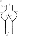
図1Aおよび1Bは、ポリマー心臓弁の1つの態様100を示している。この心臓弁は、中心軸116に沿って中心軸116の周囲を流入端から流出端まで延在する導管115を有する環状、ほぼ円筒形の、弾性の弁本体110を含む。弁100は、各々が本体110の中心軸116付近を先端134とする一対の自由縁部132を有する少なくとも3枚の屈曲性弁葉130を含む。各弁葉は連結縁部133で弁本体110に連結されており、それによって連結湾曲部が規定されている。弁葉の各々の対は、それらの間に交連部135を規定している。いくつかの態様において、弁本体110は、本体110の周囲を軸方向に延在し、各々がそれぞれの弁葉の遠位に位置する少なくとも3つの洞状突出部120を含む。1つの態様において、本体110、洞状突出部120、および弁葉130は、生体適合性ポリマーから製造することができる。
1A and 1B illustrate one
示されているように、弁葉130は、静止時(すなわち、弁に対する順行または逆行の液圧が存在しないとき)に部分開口位置にあるよう鋳造されている。例えば、静止時位置にある弁の開口面積(例えば、弁を通る液体の流れに供される開口断面積)は、弁葉130の非存在下での弁の開口面積の適切な割合のものであり得る。いくつかの態様において、部分開口静止時位置における開口面積は、その開口面積の5%を超える、10%、25%またはそれ以上、例えば、5〜10%、10〜20%、10〜30%の範囲または任意のその他の適切な範囲であり得る。
As shown, the
この構成は、順行血流時の弁葉の開口に必要なエネルギーを、静止時に閉口位置となるよう形成された同等の弁の開口に必要なエネルギーよりも小さくする。部分開口静止位置となるよう形成された場合の弁100の相対的開口容易性は、順行流圧力損失を減少させる。例えば、図7は、部分開口静止時位置となるよう形成された例示的な弁における順行流が、閉口静止時位置となるよう形成された同等の弁よりも改善されていることを図示している。
This configuration makes the energy required for the opening of the leaflets during antegrade blood flow smaller than the energy required for the opening of an equivalent valve formed to be in the closed position when stationary. The relative ease of opening of the
さらに、部分開口静止位置という弁葉130の幾何学形状は、順行流に応じた弁葉の対称開口の実現を助けている。例えば、部分開口静止構成の弁葉130を提供することにより、弁は、隣接する弁葉130の1つまたは複数の対の自由縁部の互いに対する望ましくない接着を回避することができる。これにより、弁葉130の間の交連部135におけるおよび各弁葉130より遠位にある洞状突出部120における遅い流速が防止される。以下で詳細に議論するように、遅い液流および/または非対称な流動パターンを回避することにより、悪影響、例えば血栓形成を、減少または排除すらすることができる。
In addition, the
図1Cに詳細に示されているように、隣接する弁葉130の、それぞれの交連部に最も近い静止時開口は、0.1 mmから0.6 mmの範囲である。1つの態様において、静止時開口は0.25 mmである。以下でより詳細に議論するように、弁葉130を静止時に部分開口位置となるよう設定するために、型枠、例えば先細型枠を弁本体110に設置して弁葉130を部分開口位置にし、その後に弁100を焼鈍して弁葉130に型枠の除去後も残存する部分開口位置の「記憶」を与える。以下に示す実施例では先細円錐形の型枠が使用されているが、弁葉130を部分開口位置で保持するのに任意の適切に成形された型枠(例えば、円筒形の型枠)が使用され得ることに留意されたい。
As shown in detail in FIG. 1C, the resting apertures of
使用時に、血液が順方向、すなわち図1Aに示される矢印Fの方向に(弁本体110の流入端から流出端に向かって)流れる場合、血流の圧力により弁葉130は弁本体110の中心軸116から離れる方に偏る。この「開口」位置において、弁葉130は、血液が順方向に自由に流れることができるようにする大きな流動オリフィス(図示されず)を規定する。弁葉130が開口位置にあるため、弁100は液流に対して小さな抵抗しか与えない。血液が逆方向、すなわち図1Aに示される矢印Rの方向に(弁本体110の流出端から流入端に向かって)流れる場合、血流の圧力により洞状突出部120は満たされ、それによって弁葉130は中心軸116に向かう方に偏る。この「閉口」位置において、各弁葉130は、それらの自由縁部132に沿って隣接する弁葉130と咬み合い、それによって弁100は逆流に対して封鎖される。
In use, when blood flows in the forward direction, that is, in the direction of arrow F shown in FIG. 1A (from the inflow end to the outflow end of the valve body 110), the
図2は、図1Aおよび1Bのポリマー心臓弁100の弁葉130の弁葉厚みプロファイルである。示されているように、各弁葉130a、130bおよび130cは、4点の厚みプロファイルによって特徴付けられる。示されているように、第1点は、弁葉130aの先端付近(例えば、先端から約1 mm以内)に位置する。第2点および第4点は、弁葉130aの連結縁部133付近(例えば、縁部から約1 mm以内)の、隣接する弁葉130bおよび130cのそれぞれと形成している交連部135近辺(例えば、交連部から約1 mm以内)に位置する。第3点は、連結縁部133付近(例えば、縁部から約1 mm以内)の、第2点と第4点の間に位置する。
FIG. 2 is a leaflet thickness profile of the
いくつかの用途において、弁葉のプロファイルは、弁の使用時の弁葉130の完全性(integrity)に重要となる。正しい厚みプロファイルは、弁100の信頼性を向上させ、順行流の圧力損失を減少させる。いくつかの態様において、弁葉130aは、本体110から先端134に向かって延在する方向に先細となるものである。したがって、第1点の厚みは、第2点および第4点の厚みより小さいものであり得る。例えば、いくつかの態様において、第1点の厚みは、第2点および第3点の厚みの約3分の2未満、第2点および第4点の厚みの約3分の2未満、またはそれ未満、例えば第2点および第4点の厚みの約2分の1から約3分の2の範囲である。
In some applications, the leaflet profile is important for the integrity of the
いくつかの態様において、弁葉130aは、その中心領域よりもその自由縁部132付近が厚いものである。したがって、第3点の厚みは、第2点および第4点の厚みよりも小さいものであり得る。例えば、いくつかの態様において、第3点の厚みは、第2点および第4点の厚みの約3分の2またはそれ未満、例えば、第2点および第4点の厚みの約2分の1から約3分の2の範囲である。いくつかの態様において、弁葉130aの厚みは、「スコップ(scoop)」形状プロファイルを形成するよう、第1、2、3および4点の間で連続的に変化するものである。
In some embodiments, the leaflet 130a is thicker near its
厚みプロファイル点の各々の例示的な厚み範囲が表1に示されている。表1に示されている厚み範囲は、例えば血管補助装置において使用する弁に適したものである。 An exemplary thickness range for each of the thickness profile points is shown in Table 1. The thickness range shown in Table 1 is suitable for a valve used in, for example, a blood vessel assist device.
(表1)厚みプロファイル(mm)
(表2)厚みプロファイル(mm)
言うまでもなく、様々な用途において、他の適切な厚みプロファイルが使用され得る。弁100が置換用心臓弁インプラントに含まれるいくつかの用途において、弁葉130は、上記の表2に示されている厚みプロファイルを有し得る。この例は、表1の例の厚みプロファイルの比率を維持しているが、全体的に薄くなっていることに留意されたい。様々な態様において、比率を維持しつつ他の厚みが提供され得る。さらなる態様において、他の適切な比率が使用され得る。
Of course, other suitable thickness profiles may be used in various applications. In some applications where the
図3Aおよび3Bは、先行技術にしたがう閉口静止位置を有するように形成された例示的な弁(図3A)および本明細書に記載される態様にしたがう部分開口静止位置となるよう形成された同等の例示的な弁100(図3B)の平均流速プロットを示している。擬似循環閉回路を使用し、大動脈の位置でのこれら2つのポリマー三葉心臓弁の全心周期中の流動場を評価した。(図1Aに示されているように)各弁を導管内に構築し、これを擬似閉回路の50 cc心室の流出ポートに連結した。この閉回路において使用した液体は、可能な限り導管の屈折率に近づけるよう、容積で12%のグリセリン、28%の水および60%のヨウ化ナトリウム溶液からなるニュートン血液類似物とした。この液体は、1.91 g/cm3の密度、3.77センチストークスの動粘度および1.51の屈折率を有していた。 3A and 3B are exemplary valves configured to have a closed rest position according to the prior art (FIG. 3A) and equivalents configured to be a partially open rest position according to embodiments described herein. FIG. 3 shows an average flow velocity plot for an exemplary valve 100 (FIG. 3B). A simulated circulatory closed circuit was used to evaluate the flow field during the whole cardiac cycle of these two polymer trilobal heart valves at the aortic location. Each valve was constructed in a conduit (as shown in FIG. 1A) and connected to the outlet port of a 50 cc ventricle in a pseudo-closed circuit. The liquid used in this closed circuit was a Newtonian blood analog consisting of 12% glycerin, 28% water and 60% sodium iodide solution by volume, as close as possible to the refractive index of the conduit. This liquid had a density of 1.91 g / cm 3 , a kinematic viscosity of 3.77 centistokes and a refractive index of 1.51.
各弁は、90拍/分の心拍数、4.5リットル/分の流速、および35%の収縮期で試験した。閉回路における流速は、弁のおよそ8インチ下流に設置した超音波流速計(Transonic Systems, Ithaca, NY)を用いて測定した。どちらの弁についても、データ収集の間ほぼ生理学的な心房圧および大動脈圧を維持した。一次元レーザードップラー速度測定システムを使用し、流動場内の60点における流れに沿う軸流速度を測定した。 Each valve was tested at a heart rate of 90 beats / minute, a flow rate of 4.5 liters / minute, and 35% systole. The flow velocity in the closed circuit was measured using an ultrasonic anemometer (Transonic Systems, Ithaca, NY) installed approximately 8 inches downstream of the valve. Both valves maintained near physiological atrial and aortic pressures during data collection. A one-dimensional laser Doppler velocity measurement system was used to measure the axial velocity along the flow at 60 points in the flow field.
図1Aに関して、弁葉130の基部から0.7インチおよび弁葉130の基部から1インチのところにある2平面のデータを収集した。各空間的位置において(0.1インチ間隔)、十分な回数の心周期から10,000の速度測定値を得た。事後処理の中で、データを、全心周期(667 ms)から10msの時間ビン(bin)に分割した。図3Aおよび3Bは、それぞれ、閉口および部分開口ポリマー弁におけるピーク収縮時の平均速度を示している。
With respect to FIG. 1A, two planes of data were collected 0.7 inches from the base of the
図3A(閉口静止時弁)は、最大1 m/sの逆流が弁葉の1枚(左下隅)の背後の相当な領域に及んでいる非対称な流動場を明確に示しており、この弁葉が完全に開口していないことが示唆される。他の2枚の弁葉の背後には微量の逆流が存在し、その最高逆行平均速度は-0.98 m/sである。これらの逆行流動場は、血栓形成の可能性がある領域を示している。中心オリフィスにおいてはピーク収縮時に2.79 m/s程度のピーク平均速度が存在し、これがおよそ30 msの心周期の間持続する(図示されず)。測定された最大速度は3.56 m/sであり、最大逆行速度は-1.63 m/sであった。交連部付近の流れは、2枚の弁葉間(右上隅)でのみ大きく、他の弁葉間ではそれより遅い速度が見られた。弁葉間での遅い速度は、血栓形成をもたらし得るものである。 Figure 3A (valve closed valve) clearly shows an asymmetric flow field in which a reverse flow of up to 1 m / s extends over a considerable area behind one leaflet (lower left corner). This suggests that the leaves are not completely open. There is a small amount of backflow behind the other two leaflets, with a maximum retrograde average velocity of -0.98 m / s. These retrograde flow fields indicate areas where thrombus formation is possible. At the central orifice, there is a peak average velocity on the order of 2.79 m / s during peak contraction, which lasts for a cardiac cycle of approximately 30 ms (not shown). The maximum speed measured was 3.56 m / s and the maximum retrograde speed was -1.63 m / s. The flow near the commissure was large only between the two leaflets (upper right corner), and a slower speed was seen between the other leaflets. The slow rate between the leaflets can lead to thrombus formation.
図3B(部分開口静止時弁)は、同じ流速でより良好な(例えばより対称な)全体流動パターンを示しており、交連部間でも十分な流動が見られる。閉口弁と比較して、同程度であるがより広範囲に及んでいるピーク速度(2.99 m/s)および各弁葉背後の逆流(-0.84 m/s)が見られ、これらの領域でより良好な洗い流しが行われていることが示されている。測定された最高順行速度は3.56 m/sであり、最大逆行速度はわずかに高い-1.67 m/sであった。閉口弁と異なり、開口型弁の3枚の弁葉はすべて、より一貫した挙動を示しており、それは均一な流動場により証明されている。この流動場は、およそ30 msの間展開および持続する。このように、データは、開口型弁が、閉口型弁と比較して同等のまたは潜在的に改善された血液適合性を有することを示唆している。開口型弁は、すべての弁葉間の交連部領域において優れた洗い流しを示す。例えば、図3Bに示されているように、約2.0 m/sまたはそれ以上の流速が、交連部に直接的に隣接する領域において見出される。逆流は、すべての弁葉の背後に対称に分布しており、これが、各弁葉の遠位に位置する洞状突出部において適切な渦形成(例えば、ヴァルサルバ洞に実質的に共形のもの)を促す。 FIG. 3B (partially open valve) shows a better (eg, more symmetric) overall flow pattern at the same flow rate, with sufficient flow between commissures. Compared to closure valves, but with a similar but more extensive peak velocity (2.99 m / s) and backflow behind each leaflet (-0.84 m / s), better in these areas It is shown that cleansing is taking place. The maximum forward speed measured was 3.56 m / s, and the maximum reverse speed was slightly higher, 1.67 m / s. Unlike the closed valve, all three leaflets of the open valve behave more consistently, as evidenced by a uniform flow field. This flow field develops and persists for approximately 30 ms. Thus, the data suggests that the open valve has a comparable or potentially improved hemocompatibility compared to the closed valve. Open valves show excellent flushing in the commissural region between all leaflets. For example, as shown in FIG. 3B, a flow rate of about 2.0 m / s or more is found in the region directly adjacent to the commissure. The backflow is distributed symmetrically behind all the leaflets, which is suitable for vortex formation (eg, substantially conformal to the Valsalva sinus) at the sinusoidal protrusion located distal to each leaflet. ).
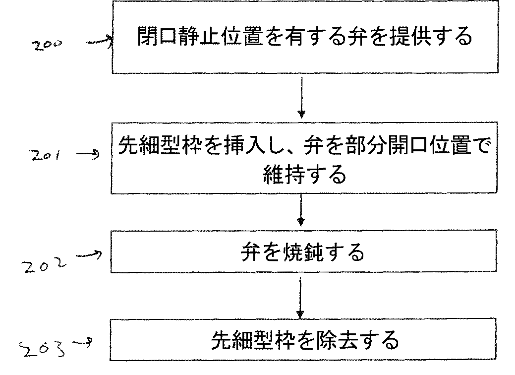
図4は、本明細書中に記載される形式の弁100を製造する方法の例示的なフローダイアグラムを示している。第1工程200では、ポリマー弁100(例えば、図1Aおよび1Bに示されるのと同様の三葉弁)が提供され、これは図5Aに図示されているような、その静止位置で実質的に閉口しているものである。すなわち、隣接する弁葉130の自由縁部は互いに接触しており、そのため導管115を通る液流が実質的に妨げられている。いくつかの態様において、弁の静止位置は、隣接する弁葉130の自由縁部がそれらの全長にわたって互いに接触し、点300において(例えば、三弁葉における三重点)一箇所に集まり、導管115を封鎖するような、完全に閉口するものである。
FIG. 4 shows an exemplary flow diagram of a method of manufacturing a
閉口位置となるよう形成されるポリマー弁は、当技術分野で公知の任意の技術を用いて構築され得る。例えば、いくつかの態様は、その全内容が参照により本明細書に組み入れられる、1908年12月9日に発行された米国特許第4,888,009号に記載される製作技術の1つまたは複数を使用するものである。いくつかのそのような態様では、屈曲性ポリマー材料が溶解、例えば揮発性溶媒中に溶解され、均質なシロップ状のポリマー溶液(例えば、Abiomed of Danvers, MAから入手することができるAngioflex Valve Pouring Solution)が形成される。鋳込み溶液(pouring slution)として任意のポリマー物質を使用できることを理解されたい。 The polymer valve formed to be in the closed position can be constructed using any technique known in the art. For example, some embodiments use one or more of the fabrication techniques described in US Pat. No. 4,888,009 issued Dec. 9, 1908, the entire contents of which are incorporated herein by reference. Is. In some such embodiments, the flexible polymeric material is dissolved, eg, dissolved in a volatile solvent, and a homogeneous syrupy polymer solution (eg, Angioflex Valve Pouring Solution available from Abiomed of Danvers, MA). ) Is formed. It should be understood that any polymeric material can be used as a pouring slution.
拡張導管、例えば約0.3 mm厚の拡張導管を形成するために、所望の導管115(例えば、図1Aに示されているような洞状突出部120を含む下流導管)の内側のそれよりもわずかに大きい直径の部分およびステントの山と谷(peak and valley)に続いて輪郭に沿って始まるより幅広の部分を有する高度に研磨された導管用マンドレルが、乾燥期間をはさんで繰り返しポリマー溶液に浸漬される。この導管アセンブリは、マンドレルからはがし取られる。
Slightly less than that inside the desired conduit 115 (eg, a downstream conduit including a
閉口した弁葉の上流側の輪郭に適合する高度に研磨された弁葉マンドレルが導管115に挿入され、慎重に位置合わせされる。次いで導管にポリマー溶液が鋳込みされる。例えば、Angioflex弁用鋳込み溶液が、1つの洞状突出部の湾曲に沿って導管に鋳込みされ、導管/マンドレルアセンブリが45度の角度から徐々に傾けられて直立位置に戻され、上部からおよそ1/8''まで導管が満たされ得る。次いで鋳込み溶液が、隣接する洞状突出部を介して導管から除去され得る。このアセンブリは、溶液を乾燥させつつゆっくりと回転させられ、導管の内側と一体的につながっている可塑性ポリマー材料の薄い弁葉が形成される。このプロセスは、弁葉が所望の厚み、例えば約0.4 mm厚になるまで繰り返される。
A highly polished leaflet mandrel that fits the upstream contour of the closed leaflet is inserted into the
いくつかの態様において、回転プロセスは、異なる被覆ごとに異なる向きで実施され得る。例えば、1つの態様において、回転は、最初の3回の被覆が行われる間は導管を直立方向に向け、そして残りの鋳込み(例えば、6回の追加の鋳込み)においては回転角度を変化させて、例えば5度を超える角度、例えば9度に変化させて、実施される。いくつかの態様において、弁は、所望の厚みプロファイルを得るため、硬化プロセスの間、回転を制御する自動装置に設置され得る。 In some embodiments, the rotation process can be performed in different orientations for different coatings. For example, in one embodiment, the rotation is accomplished by directing the conduit upright during the first three coatings and changing the rotation angle for the remaining castings (eg, six additional castings). For example, the angle is changed to more than 5 degrees, for example, 9 degrees. In some embodiments, the valve can be installed in an automated device that controls rotation during the curing process to obtain the desired thickness profile.
乾燥後、導管・弁葉アセンブリは、弁葉マンドレルからはがし取られる。さらなる乾燥が必要な場合、導管・弁葉アセンブリは、乾燥するまで、例えば24時間またはそれ以上、オーブンで、例えば40℃で加熱され得る。 After drying, the conduit and leaflet assembly is peeled away from the leaflet mandrel. If further drying is required, the conduit and leaflet assembly can be heated in an oven, eg, 40 ° C., until dry, eg, 24 hours or longer.
導管の端部は、所望の長さに切断され得る。例えば、1つの態様において、弁100の流出端は、洞の底部から約32 mmとなるようトリミングされ得る。
The end of the conduit can be cut to a desired length. For example, in one embodiment, the outflow end of the
いくつかの態様において、少なくとも1つの縫合用リング(図示されず)が、洞状突出部および弁葉の上部または下部で本体に結合され、弁を移植する際に縫合を行う場所が提供される。弁葉130は、所望の形状および厚みプロファイル(例えば、先に詳述されているようなプロファイル)を有するよう、例えば材料を高精度に除去する熱線を用いてトリミングされ得る。
In some embodiments, at least one suturing ring (not shown) is coupled to the body at the top or bottom of the sinusoidal protrusion and leaflets to provide a place to suture when implanting the valve. . The
工程201では、図5Cに図示されているように、弁葉130を部分開口位置で維持するために先細型枠301が弁100の導管115に挿入される。先細型枠301は、円錐形およびピラミッド形を含む任意の適切な形状を有する先細部分を有し得る。先細部分は、一点に集まる、丸みをおびている、または面取り(truncated)されているものであり得る。先細部分は、任意の傾斜、例えば10度超、20度、25度、45度またはそれ以上、例えば約25度を有し得る。
In
工程202では、焼鈍またはその他の方法により弁アセンブリを部分開口静止位置で固定するために、弁100が加熱、例えばオーブンで加熱される。弁100は、任意の適切な温度、例えば、100℃を超える温度、125℃、130℃またはそれ以上に加熱され得る。加熱は、任意の適切な時間、例えば1時間またはそれ以上継続され得る。加熱の後には、冷却期間、例えば弁が室温に戻るのに十分な、例えば数時間またはそれ以上の冷却期間が置かれ得る。
In
工程203では、先細型枠203が除去される。焼鈍プロセスにより、弁葉130は静止時に部分開口位置を維持している。したがって、得られるデバイスは、例えば図1Aおよび1Bに示されるような、完成形の弁100に対応するものである。
In step 203, the tapered mold 203 is removed. Due to the annealing process, the
弁を開口位置で形成する1つの例示的な方法が記載されているのであり、他も使用され得ることに留意されたい。いくつかの態様において、弁は、開口位置となるよう成型(mold)される(例えば、鋳込成型技術を用いて)。いくつかのそのような事例において、成型された弁は、弁葉の間に、弁葉を分離させるために使用され得る接ぎ材料(connecting material)を含み得る。接ぎ材料はその後、例えば、レーザー切断、熱線切断または機械的切断技術を用いて、弁葉を分離させるように切断され得る。レーザー切断は特に、超高精度の切断を提供し、滑らかで直線的な弁葉縁部を実現し得る点で有利である。 It should be noted that one exemplary method of forming the valve in the open position has been described and others can be used. In some embodiments, the valve is molded into an open position (eg, using a casting technique). In some such cases, the molded valve may include a connecting material that can be used to separate the leaflets between the leaflets. The joining material can then be cut to separate the leaflets using, for example, laser cutting, hot wire cutting or mechanical cutting techniques. Laser cutting is particularly advantageous in that it provides ultra-high precision cutting and can achieve a smooth and straight leaflet edge.
図6A〜6Gは、静止時に部分開口位置にあるポリマー心臓弁の弁葉を鋳造する方法の態様を示す画像である。第1に、弁400をマンドレル410に滑り込ませる。次に、流入側弁ステント420がステントホルダー430に挿入される。弁400およびマンドレル410は、その後、図6Bに示されているようにステント420が弁の導管を抱きかかえる状態になるまで、ステントホルダー430に挿入される。この後、弁葉は、実質的に閉口している位置で対称に並んでいるはずである。1つの態様において、弁葉は、顕微鏡を用いて観察および位置合わせすることができる。次に、位置合わせした後、ステント420が、例えばUV硬化接着剤を用いてその場に固着される(図6C)。
6A-6G are images showing an embodiment of a method of casting a leaflet of a polymer heart valve in a partially open position when at rest. First, the
図6Dに示されているように、弁用成形コーン440は、ピン450が3つすべての交連部の交連壁に接触するよう、弁アセンブリ400内に設置される。弁の弁葉はこの段階で部分的に開口され、コーンの先端が弁葉の先端の間の中心に位置している(図4E)。
As shown in FIG. 6D, the valve forming cone 440 is installed in the
このアセンブリはオーブンに入れられ、そして弁アセンブリは、弁葉が成形コーン440の除去後も部分開口位置を維持するよう焼鈍される。1つの態様において、オーブンは、適切な時間、例えば60分間またはそれ以上の間、100℃を超える、例えば125℃±2の範囲の温度に設定される。 This assembly is placed in an oven and the valve assembly is annealed so that the leaflets maintain the partially open position after removal of the forming cone 440. In one embodiment, the oven is set to a temperature in excess of 100 ° C., for example in the range of 125 ° C. ± 2, for a suitable time, for example 60 minutes or longer.
このアセンブリは、オーブンから取り出され、冷却される(例えば、2時間またはそれ以上)。成形コーン440およびピン450は、弁400から除去される。弁は、交連部が適切に開口していることについて検査され得る(図6F)。同様に、弁葉が、適切に開口していることについて検査され得る(図6G)。様々な態様において、弁葉は示さるような特定の構成で生成されない場合があるが、概してコーン440により付与される形跡を維持している部分開口形状を有するものであることを理解されたい。
The assembly is removed from the oven and cooled (eg, 2 hours or longer). Molding cone 440 and pin 450 are removed from
静止時に部分開口位置にあるポリマー心臓弁の弁葉を鋳造する他の方法を利用できることを理解されたい。 It should be understood that other methods of casting the leaflets of a polymer heart valve that is in a partially open position when stationary can be utilized.
本明細書中に開示されている態様は、あらゆる面で、例示にすぎず、本発明を限定するものではないとみなされるべきである。本明細書中に記載されている技術は、いかなるかたちであれ、上記の態様に限定されるものではない。その態様に対して、本発明の精神および範囲から逸脱することなく、様々な修正および変更が為され得る。本発明の範囲は、それらの態様ではなく、添付の特許請求の範囲によって示されている。特許請求の範囲の意義およびその等価な範囲内で実現する様々な修正および変更は、本発明の範囲に包含されることが意図されている。 The aspects disclosed herein are to be considered in all respects only as illustrative and not restrictive. The technique described in the present specification is not limited to the above-described embodiment in any way. Various modifications and changes may be made to the embodiments without departing from the spirit and scope of the invention. The scope of the invention is indicated by the appended claims rather than by those embodiments. Various modifications and changes that come within the meaning and range of equivalency of the claims are intended to be embraced within the scope of the invention.
Claims (41)
該本体から該導管内へと延在し、該本体との連結湾曲部を各々規定する、少なくとも3枚の屈曲性弁葉と
を含む、ポリマー心臓弁であって、
該弁葉のそれぞれの対が、各々、該本体の近位に位置する交連部を規定し、
該少なくとも3枚の弁葉のそれぞれは、該弁葉の中心領域よりも該弁葉の自由縁部付近が厚く、かつ
該少なくとも3枚の弁葉が、
静止時の部分開口位置、
流入端から流出端への方向に沿う順行血流時の、中心軸から離れる方に偏った完全開口位置、および
流出端から流入端への方向に沿う逆行血流時の、中心軸に向かう方に偏った閉口位置
を規定する、
前記ポリマー心臓弁。 A valve body including a conduit having a central axis and extending from the inflow end to the outflow end along the central axis;
A polymer heart valve comprising at least three bendable leaflets extending from the body into the conduit and each defining a connecting curve with the body;
A respective pair of leaflets each define a commissure located proximal to the body;
Each of the at least three leaflets is thicker near the free edge of the leaflets than the central region of the leaflets, and the at least three leaflets are
Partial opening position when stationary,
Full opening position biased away from the central axis during antegrade blood flow along the direction from the inflow end to the outflow end, and toward the central axis during retrograde blood flow along the direction from the outflow end to the inflow end The closing position biased toward
The polymer heart valve.
該プロファイルの第1点が、実質的に弁葉の先端に位置し;
該プロファイルの第2点および第4点が、実質的にそれぞれの交連部に位置し;
第3点が、実質的に、本体の近位の、連結湾曲部に沿って第2点と第4点の実質的に中間に位置する、
請求項6記載のポリマー心臓弁。 Each of the at least three leaflets has a thickness profile of at least four points including a first point, a second point, a third point, and a fourth point;
The first point of the profile is located substantially at the tip of the leaflet;
The second and fourth points of the profile are located substantially at their commissures;
A third point is located substantially intermediate the second point and the fourth point along the connecting curve, proximal to the body;
7. The polymer heart valve according to claim 6.
該本体から該導管内へと延在し、該本体との連結湾曲部を各々規定する、少なくとも3枚の屈曲性弁葉と
を含み、
該弁葉のそれぞれの対が、各々、該本体の近位に位置する交連部を規定し、かつ
該弁葉が、実質的に閉口した静止時位置にあり、
該少なくとも3枚の弁葉のそれぞれは、該弁葉の中心領域よりも該弁葉の自由縁部付近が厚い、
ポリマー弁
を形成する工程;
少なくとも3枚の弁葉を部分開口位置で維持するために先細型枠を導管に挿入する工程;
少なくとも3枚の弁葉の静止時位置を部分開口位置で固定するためにポリマー弁を加熱する工程;ならびに
加熱後に型枠を除去する工程
を含む、ポリマー心臓弁の製造方法。 A valve body including a conduit having a central axis and extending from the inflow end to the outflow end along the central axis;
At least three bendable leaflets extending from the body into the conduit and each defining a connecting curve with the body;
Each pair of leaflets defines a commissure located proximal to the body, and the leaflets are in a substantially closed, resting position;
Each of the at least three leaflets is thicker near the free edge of the leaflets than the central region of the leaflets,
Forming a polymer valve;
Inserting a tapered form into the conduit to maintain at least three leaflets in a partially open position;
A method for producing a polymer heart valve, comprising: heating a polymer valve to fix a resting position of at least three leaflets at a partially open position; and removing the mold after heating.
該プロファイルの第1点が、実質的に弁葉の先端に位置し;
弁葉の第2点および第4点が、実質的にそれぞれの交連部に位置し;かつ
第3点が、実質的に、本体の近位の、連結湾曲部に沿って第2点と第4点の実質的に中間に位置する、
請求項26記載の方法。 The thickness profile of each leaflet is a thickness profile of at least four points including the first point, the second point, the third point, and the fourth point,
The first point of the profile is located substantially at the tip of the leaflet;
The second and fourth points of the leaflets are located substantially at their respective commissures; and the third point is substantially the second and fourth points along the connecting curve, proximal to the body. Located in the middle of the four points,
27. The method of claim 26.
該本体から該導管内へと延在し、該本体との連結湾曲部を各々規定する、少なくとも3枚の屈曲性弁葉と
を含み、
該弁葉のそれぞれの対が、各々、該本体の近位に位置する交連部を規定し、かつ
該弁葉が、実質的に閉口した静止時位置にあり、
該少なくとも3枚の弁葉のそれぞれは、該弁葉の中心領域よりも該弁葉の自由縁部付近が厚い、
ポリマー弁
を形成する工程;
少なくとも3枚の弁葉を部分開口位置で維持するために先細型枠を導管に挿入する工程;
少なくとも3枚の弁葉の静止位置を部分開口位置で固定するためにポリマー弁を加熱する工程;ならびに
加熱後に型枠を除去する工程
を含む方法によって調製された、ポリマー心臓弁。 A valve body including a conduit having a central axis and extending from the inflow end to the outflow end along the central axis;
At least three bendable leaflets extending from the body into the conduit and each defining a connecting curve with the body;
Each pair of leaflets defines a commissure located proximal to the body, and the leaflets are in a substantially closed, resting position;
Each of the at least three leaflets is thicker near the free edge of the leaflets than the central region of the leaflets,
Forming a polymer valve;
Inserting a tapered form into the conduit to maintain at least three leaflets in a partially open position;
A polymer heart valve prepared by a method comprising heating a polymer valve to fix a stationary position of at least three leaflets in a partially open position; and removing the mold after heating.
Applications Claiming Priority (3)
| Application Number | Priority Date | Filing Date | Title |
|---|---|---|---|
| US12/761,891 US10512537B2 (en) | 2010-04-16 | 2010-04-16 | Flow optimized polymeric heart valve |
| US12/761,891 | 2010-04-16 | ||
| PCT/US2011/032559 WO2011130558A1 (en) | 2010-04-16 | 2011-04-14 | Flow optimized polymeric heart valve |
Publications (2)
| Publication Number | Publication Date |
|---|---|
| JP2013524890A JP2013524890A (en) | 2013-06-20 |
| JP6038018B2 true JP6038018B2 (en) | 2016-12-07 |
Family
ID=44276063
Family Applications (1)
| Application Number | Title | Priority Date | Filing Date |
|---|---|---|---|
| JP2013505152A Active JP6038018B2 (en) | 2010-04-16 | 2011-04-14 | Polymer heart valve optimized for flow |
Country Status (8)
| Country | Link |
|---|---|
| US (3) | US10512537B2 (en) |
| EP (2) | EP2558032B1 (en) |
| JP (1) | JP6038018B2 (en) |
| AU (1) | AU2011239561B2 (en) |
| CA (1) | CA2796357C (en) |
| DK (1) | DK2558032T3 (en) |
| ES (1) | ES2887311T3 (en) |
| WO (1) | WO2011130558A1 (en) |
Cited By (4)
| Publication number | Priority date | Publication date | Assignee | Title |
|---|---|---|---|---|
| US10722631B2 (en) | 2018-02-01 | 2020-07-28 | Shifamed Holdings, Llc | Intravascular blood pumps and methods of use and manufacture |
| US11185677B2 (en) | 2017-06-07 | 2021-11-30 | Shifamed Holdings, Llc | Intravascular fluid movement devices, systems, and methods of use |
| US11511103B2 (en) | 2017-11-13 | 2022-11-29 | Shifamed Holdings, Llc | Intravascular fluid movement devices, systems, and methods of use |
| US11964145B2 (en) | 2019-07-12 | 2024-04-23 | Shifamed Holdings, Llc | Intravascular blood pumps and methods of manufacture and use |
Families Citing this family (27)
| Publication number | Priority date | Publication date | Assignee | Title |
|---|---|---|---|---|
| US8579964B2 (en) | 2010-05-05 | 2013-11-12 | Neovasc Inc. | Transcatheter mitral valve prosthesis |
| US9308087B2 (en) | 2011-04-28 | 2016-04-12 | Neovasc Tiara Inc. | Sequentially deployed transcatheter mitral valve prosthesis |
| US9554897B2 (en) | 2011-04-28 | 2017-01-31 | Neovasc Tiara Inc. | Methods and apparatus for engaging a valve prosthesis with tissue |
| WO2013055977A1 (en) | 2011-10-13 | 2013-04-18 | The Research Foundation Of State University Of New York | Polymeric heart valve |
| US9345573B2 (en) | 2012-05-30 | 2016-05-24 | Neovasc Tiara Inc. | Methods and apparatus for loading a prosthesis onto a delivery system |
| US9572665B2 (en) | 2013-04-04 | 2017-02-21 | Neovasc Tiara Inc. | Methods and apparatus for delivering a prosthetic valve to a beating heart |
| WO2015171743A2 (en) | 2014-05-07 | 2015-11-12 | Baylor College Of Medicine | Artificial, flexible valves and methods of fabricating and serially expanding the same |
| US10507101B2 (en) | 2014-10-13 | 2019-12-17 | W. L. Gore & Associates, Inc. | Valved conduit |
| US10433952B2 (en) | 2016-01-29 | 2019-10-08 | Neovasc Tiara Inc. | Prosthetic valve for avoiding obstruction of outflow |
| EP3541462A4 (en) | 2016-11-21 | 2020-06-17 | Neovasc Tiara Inc. | Methods and systems for rapid retraction of a transcatheter heart valve delivery system |
| US10653523B2 (en) | 2017-01-19 | 2020-05-19 | 4C Medical Technologies, Inc. | Systems, methods and devices for delivery systems, methods and devices for implanting prosthetic heart valves |
| US10561495B2 (en) | 2017-01-24 | 2020-02-18 | 4C Medical Technologies, Inc. | Systems, methods and devices for two-step delivery and implantation of prosthetic heart valve |
| US11523940B2 (en) | 2017-03-17 | 2022-12-13 | W. L. Gore & Associates, Inc. | Delivery aids for glaucoma shunts |
| CN111263622A (en) | 2017-08-25 | 2020-06-09 | 内奥瓦斯克迪亚拉公司 | Sequentially deployed transcatheter mitral valve prosthesis |
| US11039919B2 (en) | 2017-10-31 | 2021-06-22 | W. L. Gore & Associates, Inc. | Valved conduit |
| DE102018201030A1 (en) | 2018-01-24 | 2019-07-25 | Kardion Gmbh | Magnetic coupling element with magnetic bearing function |
| DE102018211327A1 (en) | 2018-07-10 | 2020-01-16 | Kardion Gmbh | Impeller for an implantable vascular support system |
| US11857441B2 (en) | 2018-09-04 | 2024-01-02 | 4C Medical Technologies, Inc. | Stent loading device |
| USD977642S1 (en) | 2018-10-29 | 2023-02-07 | W. L. Gore & Associates, Inc. | Pulmonary valve conduit |
| AU2019374743B2 (en) | 2018-11-08 | 2022-03-03 | Neovasc Tiara Inc. | Ventricular deployment of a transcatheter mitral valve prosthesis |
| US11678983B2 (en) | 2018-12-12 | 2023-06-20 | W. L. Gore & Associates, Inc. | Implantable component with socket |
| JP7438236B2 (en) | 2019-04-01 | 2024-02-26 | ニオバスク ティアラ インコーポレイテッド | Controllably deployable prosthetic valve |
| CN113924065A (en) | 2019-04-10 | 2022-01-11 | 内奥瓦斯克迪亚拉公司 | Prosthetic valve with natural blood flow |
| WO2020236931A1 (en) | 2019-05-20 | 2020-11-26 | Neovasc Tiara Inc. | Introducer with hemostasis mechanism |
| AU2020295566B2 (en) | 2019-06-20 | 2023-07-20 | Neovasc Tiara Inc. | Low profile prosthetic mitral valve |
| DE102020102474A1 (en) | 2020-01-31 | 2021-08-05 | Kardion Gmbh | Pump for conveying a fluid and method for manufacturing a pump |
| US11931253B2 (en) | 2020-01-31 | 2024-03-19 | 4C Medical Technologies, Inc. | Prosthetic heart valve delivery system: ball-slide attachment |
Family Cites Families (20)
| Publication number | Priority date | Publication date | Assignee | Title |
|---|---|---|---|---|
| US4888009A (en) | 1985-04-05 | 1989-12-19 | Abiomed, Inc. | Prosthetic heart valve |
| DE3834545A1 (en) | 1988-10-11 | 1990-04-12 | Rau Guenter | FLEXIBLE LOCKING ORGAN, PARTICULARLY HEART VALVE, AND METHOD FOR PRODUCING THE SAME |
| US4863458A (en) * | 1988-12-14 | 1989-09-05 | Carbomedics Inc. | Heart valve prosthesis having configured leaflets and mounting ears |
| US5037434A (en) | 1990-04-11 | 1991-08-06 | Carbomedics, Inc. | Bioprosthetic heart valve with elastic commissures |
| US5258023A (en) | 1992-02-12 | 1993-11-02 | Reger Medical Development, Inc. | Prosthetic heart valve |
| GB9206449D0 (en) * | 1992-03-25 | 1992-05-06 | Univ Leeds | Artificial heart valve |
| IL118149A0 (en) * | 1996-05-05 | 1996-09-12 | Rdc Rafael Dev Corp | Method for producing heart valves and heart valves produced by the method |
| GB9701479D0 (en) | 1997-01-24 | 1997-03-12 | Aortech Europ Ltd | Heart valve |
| US5843183A (en) | 1997-05-13 | 1998-12-01 | Bokros; Jack C. | Trileaflet heart valve |
| US6117169A (en) | 1998-06-24 | 2000-09-12 | Sulzer Carbomedics Inc. | Living hinge attachment of leaflet to a valve body |
| US6287338B1 (en) | 1999-03-10 | 2001-09-11 | Sulzer Carbomedics Inc. | Pre-stressing devices incorporating materials subject to stress softening |
| US6174331B1 (en) | 1999-07-19 | 2001-01-16 | Sulzer Carbomedics Inc. | Heart valve leaflet with reinforced free margin |
| US6371983B1 (en) * | 1999-10-04 | 2002-04-16 | Ernest Lane | Bioprosthetic heart valve |
| AU2571802A (en) * | 2000-11-21 | 2002-06-03 | Rex Medical Lp | Percutaneous aortic valve |
| US20070027535A1 (en) | 2005-07-28 | 2007-02-01 | Cook Incorporated | Implantable thromboresistant valve |
| US6916338B2 (en) * | 2001-03-16 | 2005-07-12 | Mayo Foundation For Medical Education And Research | Synthetic leaflets for heart valve repair or replacement |
| US20030114924A1 (en) | 2001-12-18 | 2003-06-19 | Riyad Moe | Polymer heart valve |
| US20040024452A1 (en) | 2002-08-02 | 2004-02-05 | Kruse Steven D. | Valved prostheses with preformed tissue leaflets |
| WO2007130537A1 (en) | 2006-05-05 | 2007-11-15 | Children's Medical Center Corporation | Transcatheter heart valve prostheses |
| JP2010527745A (en) | 2007-05-25 | 2010-08-19 | メディカル エントレプレナーズ セカンド インコーポレイテッド | Prosthetic heart valve |
-
2010
- 2010-04-16 US US12/761,891 patent/US10512537B2/en active Active
-
2011
- 2011-04-14 JP JP2013505152A patent/JP6038018B2/en active Active
- 2011-04-14 AU AU2011239561A patent/AU2011239561B2/en active Active
- 2011-04-14 EP EP11716743.7A patent/EP2558032B1/en active Active
- 2011-04-14 EP EP21190736.5A patent/EP3967270A1/en active Pending
- 2011-04-14 WO PCT/US2011/032559 patent/WO2011130558A1/en active Application Filing
- 2011-04-14 ES ES11716743T patent/ES2887311T3/en active Active
- 2011-04-14 DK DK11716743.7T patent/DK2558032T3/en active
- 2011-04-14 CA CA2796357A patent/CA2796357C/en active Active
-
2019
- 2019-10-16 US US16/654,701 patent/US11298224B2/en active Active
-
2022
- 2022-03-04 US US17/687,295 patent/US20220313425A1/en active Pending
Cited By (5)
| Publication number | Priority date | Publication date | Assignee | Title |
|---|---|---|---|---|
| US11185677B2 (en) | 2017-06-07 | 2021-11-30 | Shifamed Holdings, Llc | Intravascular fluid movement devices, systems, and methods of use |
| US11511103B2 (en) | 2017-11-13 | 2022-11-29 | Shifamed Holdings, Llc | Intravascular fluid movement devices, systems, and methods of use |
| US10722631B2 (en) | 2018-02-01 | 2020-07-28 | Shifamed Holdings, Llc | Intravascular blood pumps and methods of use and manufacture |
| US11229784B2 (en) | 2018-02-01 | 2022-01-25 | Shifamed Holdings, Llc | Intravascular blood pumps and methods of use and manufacture |
| US11964145B2 (en) | 2019-07-12 | 2024-04-23 | Shifamed Holdings, Llc | Intravascular blood pumps and methods of manufacture and use |
Also Published As
| Publication number | Publication date |
|---|---|
| CA2796357A1 (en) | 2011-10-20 |
| JP2013524890A (en) | 2013-06-20 |
| US20220313425A1 (en) | 2022-10-06 |
| US20200046492A1 (en) | 2020-02-13 |
| WO2011130558A1 (en) | 2011-10-20 |
| ES2887311T3 (en) | 2021-12-22 |
| US20110257738A1 (en) | 2011-10-20 |
| DK2558032T3 (en) | 2021-09-27 |
| EP2558032A1 (en) | 2013-02-20 |
| US11298224B2 (en) | 2022-04-12 |
| AU2011239561B2 (en) | 2015-04-09 |
| US10512537B2 (en) | 2019-12-24 |
| EP2558032B1 (en) | 2021-08-18 |
| AU2011239561A1 (en) | 2012-11-08 |
| CA2796357C (en) | 2016-01-19 |
| EP3967270A1 (en) | 2022-03-16 |
Similar Documents
| Publication | Publication Date | Title |
|---|---|---|
| JP6038018B2 (en) | Polymer heart valve optimized for flow | |
| JP6035235B2 (en) | Polymer trefoil heart valve prosthesis | |
| JP6896742B2 (en) | Artificial valve with guide | |
| CA2521896C (en) | Reed valve for implantation into mammalian blood vessels and heart with temporary or permanent support by two stents | |
| JP5881653B2 (en) | Intra-annular mounting frame for aortic valve repair | |
| CN104394803B (en) | Heart valve prosthesis | |
| JP4287272B2 (en) | Polymeric valve membrane structure for medical devices | |
| US5545215A (en) | External sigmoid valve complex frame and valved conduit supported by the same | |
| US20030069635A1 (en) | Prosthetic heart valve | |
| US11464639B2 (en) | Methods for creating sinus-matched aortic valves | |
| CN108261258A (en) | Valve prosthesis and delivering method | |
| JP2003509112A (en) | Vascular treatment of chronic venous insufficiency | |
| EP2621407A2 (en) | Intra-annular mounting frame for aortic valve repair | |
| RU2416378C1 (en) | Separate cusp of artificial aortic valve and template for its obtaining | |
| JP2022529472A (en) | Naturally designed mitral valve prosthesis | |
| JP6159041B1 (en) | Artificial valve | |
| RU2747362C2 (en) | Method of prosthetic repair of all structures of right ventricular outlet, pulmonary valve, pulmonary trunk | |
| KR100604974B1 (en) | An Implant for Reconstructing the Subvalvular Structure in Atrioventricular Valve | |
| Twardowska | Early prototyping and testing of a model of an expandable heart valve apparatus for paediatric deployment | |
| Benjamin | Steady flow investigations of valved heart conduits |
Legal Events
| Date | Code | Title | Description |
|---|---|---|---|
| A621 | Written request for application examination |
Free format text: JAPANESE INTERMEDIATE CODE: A621 Effective date: 20140327 |
|
| A977 | Report on retrieval |
Free format text: JAPANESE INTERMEDIATE CODE: A971007 Effective date: 20150116 |
|
| A131 | Notification of reasons for refusal |
Free format text: JAPANESE INTERMEDIATE CODE: A131 Effective date: 20150202 |
|
| A601 | Written request for extension of time |
Free format text: JAPANESE INTERMEDIATE CODE: A601 Effective date: 20150501 |
|
| RD04 | Notification of resignation of power of attorney |
Free format text: JAPANESE INTERMEDIATE CODE: A7424 Effective date: 20150521 |
|
| A521 | Request for written amendment filed |
Free format text: JAPANESE INTERMEDIATE CODE: A523 Effective date: 20150731 |
|
| A131 | Notification of reasons for refusal |
Free format text: JAPANESE INTERMEDIATE CODE: A131 Effective date: 20151130 |
|
| A601 | Written request for extension of time |
Free format text: JAPANESE INTERMEDIATE CODE: A601 Effective date: 20160225 |
|
| A521 | Request for written amendment filed |
Free format text: JAPANESE INTERMEDIATE CODE: A523 Effective date: 20160526 |
|
| TRDD | Decision of grant or rejection written | ||
| A01 | Written decision to grant a patent or to grant a registration (utility model) |
Free format text: JAPANESE INTERMEDIATE CODE: A01 Effective date: 20161017 |
|
| A61 | First payment of annual fees (during grant procedure) |
Free format text: JAPANESE INTERMEDIATE CODE: A61 Effective date: 20161101 |
|
| R150 | Certificate of patent or registration of utility model |
Ref document number: 6038018 Country of ref document: JP Free format text: JAPANESE INTERMEDIATE CODE: R150 |
|
| R250 | Receipt of annual fees |
Free format text: JAPANESE INTERMEDIATE CODE: R250 |
|
| R250 | Receipt of annual fees |
Free format text: JAPANESE INTERMEDIATE CODE: R250 |
|
| R250 | Receipt of annual fees |
Free format text: JAPANESE INTERMEDIATE CODE: R250 |
|
| R250 | Receipt of annual fees |
Free format text: JAPANESE INTERMEDIATE CODE: R250 |
|
| RD02 | Notification of acceptance of power of attorney |
Free format text: JAPANESE INTERMEDIATE CODE: R3D02 |
|
| R250 | Receipt of annual fees |
Free format text: JAPANESE INTERMEDIATE CODE: R250 |