JP6037204B2 - Storage element and conductive member - Google Patents
Storage element and conductive member Download PDFInfo
- Publication number
- JP6037204B2 JP6037204B2 JP2012133079A JP2012133079A JP6037204B2 JP 6037204 B2 JP6037204 B2 JP 6037204B2 JP 2012133079 A JP2012133079 A JP 2012133079A JP 2012133079 A JP2012133079 A JP 2012133079A JP 6037204 B2 JP6037204 B2 JP 6037204B2
- Authority
- JP
- Japan
- Prior art keywords
- case
- main body
- conductive member
- central axis
- terminal
- Prior art date
- Legal status (The legal status is an assumption and is not a legal conclusion. Google has not performed a legal analysis and makes no representation as to the accuracy of the status listed.)
- Active
Links
Images


Classifications
-
- H—ELECTRICITY
- H01—ELECTRIC ELEMENTS
- H01M—PROCESSES OR MEANS, e.g. BATTERIES, FOR THE DIRECT CONVERSION OF CHEMICAL ENERGY INTO ELECTRICAL ENERGY
- H01M50/00—Constructional details or processes of manufacture of the non-active parts of electrochemical cells other than fuel cells, e.g. hybrid cells
- H01M50/50—Current conducting connections for cells or batteries
- H01M50/543—Terminals
-
- H—ELECTRICITY
- H01—ELECTRIC ELEMENTS
- H01G—CAPACITORS; CAPACITORS, RECTIFIERS, DETECTORS, SWITCHING DEVICES OR LIGHT-SENSITIVE DEVICES, OF THE ELECTROLYTIC TYPE
- H01G11/00—Hybrid capacitors, i.e. capacitors having different positive and negative electrodes; Electric double-layer [EDL] capacitors; Processes for the manufacture thereof or of parts thereof
- H01G11/66—Current collectors
- H01G11/70—Current collectors characterised by their structure
-
- H—ELECTRICITY
- H01—ELECTRIC ELEMENTS
- H01G—CAPACITORS; CAPACITORS, RECTIFIERS, DETECTORS, SWITCHING DEVICES OR LIGHT-SENSITIVE DEVICES, OF THE ELECTROLYTIC TYPE
- H01G11/00—Hybrid capacitors, i.e. capacitors having different positive and negative electrodes; Electric double-layer [EDL] capacitors; Processes for the manufacture thereof or of parts thereof
- H01G11/74—Terminals, e.g. extensions of current collectors
-
- H—ELECTRICITY
- H01—ELECTRIC ELEMENTS
- H01G—CAPACITORS; CAPACITORS, RECTIFIERS, DETECTORS, SWITCHING DEVICES OR LIGHT-SENSITIVE DEVICES, OF THE ELECTROLYTIC TYPE
- H01G11/00—Hybrid capacitors, i.e. capacitors having different positive and negative electrodes; Electric double-layer [EDL] capacitors; Processes for the manufacture thereof or of parts thereof
- H01G11/78—Cases; Housings; Encapsulations; Mountings
- H01G11/82—Fixing or assembling a capacitive element in a housing, e.g. mounting electrodes, current collectors or terminals in containers or encapsulations
-
- H—ELECTRICITY
- H01—ELECTRIC ELEMENTS
- H01M—PROCESSES OR MEANS, e.g. BATTERIES, FOR THE DIRECT CONVERSION OF CHEMICAL ENERGY INTO ELECTRICAL ENERGY
- H01M10/00—Secondary cells; Manufacture thereof
- H01M10/04—Construction or manufacture in general
-
- H—ELECTRICITY
- H01—ELECTRIC ELEMENTS
- H01M—PROCESSES OR MEANS, e.g. BATTERIES, FOR THE DIRECT CONVERSION OF CHEMICAL ENERGY INTO ELECTRICAL ENERGY
- H01M4/00—Electrodes
- H01M4/02—Electrodes composed of, or comprising, active material
- H01M4/64—Carriers or collectors
- H01M4/70—Carriers or collectors characterised by shape or form
-
- H—ELECTRICITY
- H01—ELECTRIC ELEMENTS
- H01M—PROCESSES OR MEANS, e.g. BATTERIES, FOR THE DIRECT CONVERSION OF CHEMICAL ENERGY INTO ELECTRICAL ENERGY
- H01M50/00—Constructional details or processes of manufacture of the non-active parts of electrochemical cells other than fuel cells, e.g. hybrid cells
- H01M50/10—Primary casings, jackets or wrappings of a single cell or a single battery
- H01M50/172—Arrangements of electric connectors penetrating the casing
- H01M50/174—Arrangements of electric connectors penetrating the casing adapted for the shape of the cells
- H01M50/176—Arrangements of electric connectors penetrating the casing adapted for the shape of the cells for prismatic or rectangular cells
-
- H—ELECTRICITY
- H01—ELECTRIC ELEMENTS
- H01M—PROCESSES OR MEANS, e.g. BATTERIES, FOR THE DIRECT CONVERSION OF CHEMICAL ENERGY INTO ELECTRICAL ENERGY
- H01M50/00—Constructional details or processes of manufacture of the non-active parts of electrochemical cells other than fuel cells, e.g. hybrid cells
- H01M50/50—Current conducting connections for cells or batteries
- H01M50/528—Fixed electrical connections, i.e. not intended for disconnection
-
- H—ELECTRICITY
- H01—ELECTRIC ELEMENTS
- H01M—PROCESSES OR MEANS, e.g. BATTERIES, FOR THE DIRECT CONVERSION OF CHEMICAL ENERGY INTO ELECTRICAL ENERGY
- H01M50/00—Constructional details or processes of manufacture of the non-active parts of electrochemical cells other than fuel cells, e.g. hybrid cells
- H01M50/50—Current conducting connections for cells or batteries
- H01M50/531—Electrode connections inside a battery casing
-
- H—ELECTRICITY
- H01—ELECTRIC ELEMENTS
- H01M—PROCESSES OR MEANS, e.g. BATTERIES, FOR THE DIRECT CONVERSION OF CHEMICAL ENERGY INTO ELECTRICAL ENERGY
- H01M50/00—Constructional details or processes of manufacture of the non-active parts of electrochemical cells other than fuel cells, e.g. hybrid cells
- H01M50/50—Current conducting connections for cells or batteries
- H01M50/543—Terminals
- H01M50/547—Terminals characterised by the disposition of the terminals on the cells
- H01M50/55—Terminals characterised by the disposition of the terminals on the cells on the same side of the cell
-
- H—ELECTRICITY
- H01—ELECTRIC ELEMENTS
- H01M—PROCESSES OR MEANS, e.g. BATTERIES, FOR THE DIRECT CONVERSION OF CHEMICAL ENERGY INTO ELECTRICAL ENERGY
- H01M50/00—Constructional details or processes of manufacture of the non-active parts of electrochemical cells other than fuel cells, e.g. hybrid cells
- H01M50/50—Current conducting connections for cells or batteries
- H01M50/543—Terminals
- H01M50/564—Terminals characterised by their manufacturing process
- H01M50/567—Terminals characterised by their manufacturing process by fixing means, e.g. screws, rivets or bolts
-
- H—ELECTRICITY
- H01—ELECTRIC ELEMENTS
- H01M—PROCESSES OR MEANS, e.g. BATTERIES, FOR THE DIRECT CONVERSION OF CHEMICAL ENERGY INTO ELECTRICAL ENERGY
- H01M10/00—Secondary cells; Manufacture thereof
- H01M10/05—Accumulators with non-aqueous electrolyte
- H01M10/052—Li-accumulators
-
- H—ELECTRICITY
- H01—ELECTRIC ELEMENTS
- H01M—PROCESSES OR MEANS, e.g. BATTERIES, FOR THE DIRECT CONVERSION OF CHEMICAL ENERGY INTO ELECTRICAL ENERGY
- H01M10/00—Secondary cells; Manufacture thereof
- H01M10/34—Gastight accumulators
- H01M10/345—Gastight metal hydride accumulators
-
- H—ELECTRICITY
- H01—ELECTRIC ELEMENTS
- H01M—PROCESSES OR MEANS, e.g. BATTERIES, FOR THE DIRECT CONVERSION OF CHEMICAL ENERGY INTO ELECTRICAL ENERGY
- H01M2220/00—Batteries for particular applications
- H01M2220/20—Batteries in motive systems, e.g. vehicle, ship, plane
-
- H—ELECTRICITY
- H01—ELECTRIC ELEMENTS
- H01M—PROCESSES OR MEANS, e.g. BATTERIES, FOR THE DIRECT CONVERSION OF CHEMICAL ENERGY INTO ELECTRICAL ENERGY
- H01M2220/00—Batteries for particular applications
- H01M2220/30—Batteries in portable systems, e.g. mobile phone, laptop
-
- Y—GENERAL TAGGING OF NEW TECHNOLOGICAL DEVELOPMENTS; GENERAL TAGGING OF CROSS-SECTIONAL TECHNOLOGIES SPANNING OVER SEVERAL SECTIONS OF THE IPC; TECHNICAL SUBJECTS COVERED BY FORMER USPC CROSS-REFERENCE ART COLLECTIONS [XRACs] AND DIGESTS
- Y02—TECHNOLOGIES OR APPLICATIONS FOR MITIGATION OR ADAPTATION AGAINST CLIMATE CHANGE
- Y02E—REDUCTION OF GREENHOUSE GAS [GHG] EMISSIONS, RELATED TO ENERGY GENERATION, TRANSMISSION OR DISTRIBUTION
- Y02E60/00—Enabling technologies; Technologies with a potential or indirect contribution to GHG emissions mitigation
- Y02E60/10—Energy storage using batteries
-
- Y—GENERAL TAGGING OF NEW TECHNOLOGICAL DEVELOPMENTS; GENERAL TAGGING OF CROSS-SECTIONAL TECHNOLOGIES SPANNING OVER SEVERAL SECTIONS OF THE IPC; TECHNICAL SUBJECTS COVERED BY FORMER USPC CROSS-REFERENCE ART COLLECTIONS [XRACs] AND DIGESTS
- Y02—TECHNOLOGIES OR APPLICATIONS FOR MITIGATION OR ADAPTATION AGAINST CLIMATE CHANGE
- Y02E—REDUCTION OF GREENHOUSE GAS [GHG] EMISSIONS, RELATED TO ENERGY GENERATION, TRANSMISSION OR DISTRIBUTION
- Y02E60/00—Enabling technologies; Technologies with a potential or indirect contribution to GHG emissions mitigation
- Y02E60/13—Energy storage using capacitors
-
- Y—GENERAL TAGGING OF NEW TECHNOLOGICAL DEVELOPMENTS; GENERAL TAGGING OF CROSS-SECTIONAL TECHNOLOGIES SPANNING OVER SEVERAL SECTIONS OF THE IPC; TECHNICAL SUBJECTS COVERED BY FORMER USPC CROSS-REFERENCE ART COLLECTIONS [XRACs] AND DIGESTS
- Y02—TECHNOLOGIES OR APPLICATIONS FOR MITIGATION OR ADAPTATION AGAINST CLIMATE CHANGE
- Y02P—CLIMATE CHANGE MITIGATION TECHNOLOGIES IN THE PRODUCTION OR PROCESSING OF GOODS
- Y02P70/00—Climate change mitigation technologies in the production process for final industrial or consumer products
- Y02P70/50—Manufacturing or production processes characterised by the final manufactured product
Description
本発明は、電極体と、該電極体を収容するケースと、該ケースの隔壁を貫通する導電性部材とを備える蓄電素子及び導電性部材に関する。 The present invention relates to a power storage element and a conductive member that include an electrode body, a case that houses the electrode body, and a conductive member that penetrates a partition wall of the case.
近年、車両(自動車、自動二輪車等)や各種機器(携帯端末、ノート型パソコン等)の動力源として、電池(リチウムイオン電池、ニッケル水素電池等)やキャパシタ(電気二重層キャパシタ等)といった放充電可能な蓄電素子が採用されている。例えば、電池は、電極体と、該電極体を収容するケース本体及び該ケース本体の開口部を塞ぐ蓋板からなるケースとを備える。そして、集電体が電極体に接続され、電極体及び集電体がケース内に配置され、外部端子が例えば蓋板の外面に配置され、外部端子と集電体とが直接又は間接に接続される。これにより、外部端子と電極体とが電気的に接続される。 In recent years, batteries (lithium ion batteries, nickel metal hydride batteries, etc.) and capacitors (electric double layer capacitors, etc.) are used as power sources for vehicles (automobiles, motorcycles, etc.) and various devices (mobile terminals, notebook computers, etc.). Possible power storage elements are employed. For example, the battery includes an electrode body, a case main body that accommodates the electrode body, and a case that includes a lid plate that closes an opening of the case main body. Then, the current collector is connected to the electrode body, the electrode body and the current collector are disposed in the case, the external terminals are disposed on the outer surface of the cover plate, for example, and the external terminals and the current collector are directly or indirectly connected. Is done. Thereby, an external terminal and an electrode body are electrically connected.
外部端子と集電体とを電気的に接続する手段として、導電性部材が用いられる。導電性部材は、胴部、該胴部の下面から突出する第一かしめ部及び該胴部の上面から突出する第二かしめ部を備える補助端子と、該補助端子の第二かしめ部及び外部端子の軸部がそれぞれ挿通される二つの貫通孔を有する接続導体とで構成される。 A conductive member is used as means for electrically connecting the external terminal and the current collector. The conductive member includes a body part, a first caulking part projecting from the lower surface of the body part, and a second caulking part projecting from the upper surface of the body part, and a second caulking part and an external terminal of the auxiliary terminal And a connecting conductor having two through holes through which the shaft portions are respectively inserted.
特許文献1に記載された電池では、補助端子(補助端子8)は、胴部(台座部8a)と、第一かしめ部(第1かしめ筒8b)と、第二かしめ部(第2かしめ筒8c)とを備える。外部端子(外部端子4)は、頭部(台座部4a)と、雄ネジ部(ボルト部4b)とを備える。接続導体(接続導体9)は、貫通孔(かしめ孔9a、端子貫通孔9b)を備える。そして、封止部材(外部絶縁封止材6)を介して蓋板(蓋板3)の外面に補助端子が配置され、該補助端子の第一かしめ部がケース内の集電体(集電接続体5)の貫通孔に挿通され、該貫通孔から下方に突出する第一かしめ部の先端部分が下方からかしめられている。また、封止部材あるいは該封止部材とは別に設けられた端子回り止め部材を介して蓋板の外面に外部端子が配置され、補助端子の第二かしめ部と外部端子の雄ネジ部とが接続導体の貫通孔のそれぞれに挿通され、一方の貫通孔(かしめ孔9a)から上方に突出する第二かしめ部の先端部分が上方からかしめられている。これにより、外部端子と集電体とが補助端子及び接続導体を介して電気的に接続されている。
In the battery described in Patent Document 1, the auxiliary terminal (auxiliary terminal 8) includes a body part (
ところで、特許文献1に記載された電池では、第二かしめ部が接続導体の貫通孔に挿通され、第二かしめ部にかしめ処理が施され、補助端子と接続導体とが一体化された後、第一かしめ部がケースの隔壁に挿通されるようになっている。そのため、ケースの隔壁に挿通された第一かしめ部が集電体の貫通孔に挿通され、第一かしめ部にかしめ処理が施される際、一体化された補助端子と接続導体とが第一かしめ部へのかしめ作用力によって挿通方向軸回りに回転し、接続導体が望ましい位置からずれることがある。 By the way, in the battery described in Patent Document 1, the second caulking portion is inserted into the through hole of the connecting conductor, the caulking process is performed on the second caulking portion, and the auxiliary terminal and the connecting conductor are integrated, The first caulking portion is inserted through the partition wall of the case. Therefore, when the first caulking portion inserted through the partition wall of the case is inserted into the through hole of the current collector, and the caulking process is performed on the first caulking portion, the integrated auxiliary terminal and the connection conductor are the first. The caulking action force on the caulking portion rotates around the insertion direction axis, and the connecting conductor may deviate from a desired position.
また、この種の問題は、電池に限られず、キャパシタ(電気二重層キャパシタ等)についても同様である。 In addition, this type of problem is not limited to the battery, but also applies to capacitors (such as electric double layer capacitors).
そこで、本発明は、かかる問題に鑑みてなされたもので、導電性部材がかしめられる際にケースに対して不用意に回転するのを防止することができる蓄電素子及び導電性部材を提供することを課題とする。 Therefore, the present invention has been made in view of such problems, and provides a power storage element and a conductive member that can prevent inadvertent rotation with respect to the case when the conductive member is caulked. Is an issue.
本発明に係る蓄電素子は、
互いに絶縁された正極板と負極板とを含む電極体と、
隔壁によって構成され、電極体を収容するケースと、
隔壁を貫通し、ケース内にて電極体と電気的に接続される導電性部材とを備え、
導電性部材は、
隔壁を貫通する方向に中心軸を有する本体部と、
該本体部から突出する導体接続部とを備え、
本体部は、隔壁に挿通される側に、かしめ部を備え、反対側に、中心軸に対して非円形状となる頭部を備える。
The electricity storage device according to the present invention is:
An electrode body including a positive electrode plate and a negative electrode plate insulated from each other;
A case configured by a partition wall and containing an electrode body;
A conductive member that penetrates the partition wall and is electrically connected to the electrode body in the case;
The conductive member is
A main body having a central axis in a direction penetrating the partition;
A conductor connecting portion protruding from the main body,
The main body portion includes a caulking portion on the side inserted into the partition wall, and a head portion that is non-circular with respect to the central axis on the opposite side.
かかる構成によれば、頭部は中心軸に対して非円形状である。そのため、頭部が工具、治具等の何らかの手段により支持された状態でかしめ部にかしめ処理が施され、その際に、導電性部材がかしめ部へのかしめ作用力によって中心軸回りに回転しようとしてもその動きが規制される。これにより、導電性部材がかしめられる際にケースに対して不用意に回転するのを防止することができる。 According to this configuration, the head is noncircular with respect to the central axis. For this reason, the caulking portion is subjected to caulking processing with the head supported by some means such as a tool or jig, and at that time, the conductive member will rotate about the central axis by caulking action force on the caulking portion. However, the movement is regulated. Thereby, when a conductive member is caulked, it can prevent rotating carelessly with respect to a case.
ここで、本発明に係る蓄電素子の一態様として、
導体接続部は、本体部から中心軸と交差する方向に突出している
ようにすることができる。
Here, as one aspect of the electricity storage device according to the present invention,
The conductor connection portion may protrude from the main body portion in a direction crossing the central axis.
かかる構成によれば、導体接続部が本体部から離間する方向に展開されることで、導体接続部に対する導体の接続スペースを十分に確保することができる。 According to such a configuration, the conductor connection portion is developed in a direction away from the main body portion, so that a sufficient conductor connection space with respect to the conductor connection portion can be secured.
また、本発明に係る蓄電素子の他態様として、
隔壁に沿って配置され、かしめ部が貫通した状態で導電性部材を支持する絶縁部材をさらに備える
ようにすることができる。
Further, as another aspect of the electricity storage device according to the present invention,
An insulating member that is disposed along the partition wall and supports the conductive member in a state where the caulking portion passes therethrough can be further provided.
かかる構成によれば、絶縁部材により導電性部材と隔壁とが絶縁された状態で導電性部材と電極体とを電気的に接続することができる。 According to such a configuration, the conductive member and the electrode body can be electrically connected in a state where the conductive member and the partition are insulated by the insulating member.
この場合、
本体部は、かしめ部と頭部との間に胴部をさらに備え、
絶縁部材は、胴部を受け入れ可能な凹部を備える
ようにすることができる。
in this case,
The main body portion further includes a body portion between the caulking portion and the head portion,
The insulating member may include a recess that can receive the body.
かかる構成によれば、蓄電素子が結露などで発生する水滴や導電性雰囲気(静電気やダスト)に晒された場合であっても、絶縁部材の外壁部がカバー(あるいは遮断壁)となり、ケースと本体部との間の短絡を好適に防止することができる。 According to such a configuration, even when the power storage element is exposed to water droplets or conductive atmosphere (static electricity or dust) generated by condensation or the like, the outer wall portion of the insulating member becomes a cover (or a blocking wall), and the case and A short circuit with the main body can be suitably prevented.
さらにこの場合、
頭部と胴部とは、中心軸に対して同一乃至略同一の断面形状を有する
ようにすることができる。
In this case,
The head portion and the trunk portion can have the same or substantially the same cross-sectional shape with respect to the central axis.
かかる構成によれば、頭部と胴部との間に不必要な段差を無くすことができる。 According to such a configuration, an unnecessary step can be eliminated between the head and the trunk.
また、本発明に係る蓄電素子の別の態様として、
頭部は、角部が丸まった角形状を有する
ようにすることができる。
Moreover, as another aspect of the electrical storage element which concerns on this invention,
The head can have a square shape with rounded corners.
かかる構成によれば、頭部が角形状であるため、頭部を確実に支持することができ、また、角部が丸まっているため、当該箇所で電気抵抗値が局所的に高くなるのを防止することができる。 According to such a configuration, since the head portion has a square shape, the head portion can be reliably supported, and since the corner portion is rounded, the electrical resistance value is locally increased at the portion. Can be prevented.
また、本発明に係る蓄電素子のさらに別の態様として、
本体部は、ケースの外側から内側に向かって、隔壁に挿通され、
導体接続部は、ケース外に配置されている
ようにすることができる。
As still another aspect of the electricity storage device according to the present invention,
The main body is inserted into the partition wall from the outside to the inside of the case,
The conductor connection can be arranged outside the case.
かかる構成によれば、かしめ部がケースの内側からかしめられて導電性部材はケースに固定される。そして、導体はケース外の導体接続部に接続される。 According to this configuration, the caulking portion is caulked from the inside of the case, and the conductive member is fixed to the case. And a conductor is connected to the conductor connection part outside a case.
この場合、
ケース外に配置される外部端子をさらに備え、
導体接続部は、外部端子と電気的に接続されている
ようにすることができる。
in this case,
Further provided with external terminals arranged outside the case,
The conductor connection portion may be electrically connected to the external terminal.
かかる構成によれば、導体としての外部端子が導体接続部に接続され、例えば外部機器のリード線の圧着端子が外部端子に接続される。 According to such a configuration, the external terminal as a conductor is connected to the conductor connection portion, for example, a crimp terminal of a lead wire of the external device is connected to the external terminal.
また、本発明に係る蓄電素子の別の態様として、
本体部は、ケースの内側から外側に向かって、隔壁に挿通され、
導体接続部は、ケース内に配置されるとともに、電極体と電気的に接続されている
ようにすることができる。
Moreover, as another aspect of the electrical storage element which concerns on this invention,
The main body is inserted into the partition wall from the inside to the outside of the case,
The conductor connection portion may be disposed in the case and electrically connected to the electrode body.
かかる構成によれば、かしめ部がケースの外側からかしめられて導電性部材はケースに固定される。そして、導体はケース内の導体接続部に接続される。 According to this configuration, the caulking portion is caulked from the outside of the case, and the conductive member is fixed to the case. And a conductor is connected to the conductor connection part in a case.
また、本発明に係る蓄電素子のさらに別の態様として、
導電性部材は、鍛造によって形成されている
ようにすることができる。
As still another aspect of the electricity storage device according to the present invention,
The conductive member can be formed by forging.
かかる構成によれば、導電性部材を安価に製造することができ、製造コストを削減することができる。 According to this configuration, the conductive member can be manufactured at low cost, and the manufacturing cost can be reduced.
本発明に係る導電性部材は、
蓄電素子のケースの隔壁を貫通し、ケース内に収容される電極体をケース外に導通接続するための導電性部材であって、
隔壁を貫通する方向に中心軸を有する本体部と、
該本体部から突出する導体接続部とを備え、
本体部は、隔壁に挿通される側に、かしめ部を備え、反対側に、中心軸に対して非円形状となる頭部を備える。
The conductive member according to the present invention is
A conductive member that penetrates the partition wall of the case of the storage element and electrically connects the electrode body accommodated in the case to the outside of the case,
A main body having a central axis in a direction penetrating the partition;
A conductor connecting portion protruding from the main body,
The main body portion includes a caulking portion on the side inserted into the partition wall, and a head portion that is non-circular with respect to the central axis on the opposite side.
以上の如く、本発明によれば、本体部の中心軸に対して非円形状となる頭部を備えることによって、導電性部材がかしめられる際にケースに対して不用意に回転するのを防止することができる。 As described above, according to the present invention, by providing the head that is non-circular with respect to the central axis of the main body, it is possible to prevent the conductive member from rotating carelessly with respect to the case when the conductive member is caulked. can do.
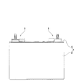
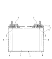
以下、本発明に係る蓄電素子の一実施形態である電池について、図面を参酌しつつ説明する。本実施形態に係る電池は、非水電解質二次電池、より詳しくは、リチウムイオン二次電池である。本実施形態に係る電池は、図1〜図4に示す如く、ケース本体2と、該ケース本体2の開口部を塞いで密閉する蓋板3とで構成されるケース1を備えている。また、蓋板3には、ケース1内に収納された電極体4と電気的に接続された端子構造9が設けられている。
Hereinafter, a battery which is an embodiment of a power storage device according to the present invention will be described with reference to the drawings. The battery according to this embodiment is a non-aqueous electrolyte secondary battery, more specifically, a lithium ion secondary battery. As shown in FIGS. 1 to 4, the battery according to the present embodiment includes a case 1 including a case body 2 and a
ケース1のケース本体2及び蓋板3は、アルミニウム又はアルミニウム合金のアルミニウム系金属材料で形成される。ケース本体2は、長円筒形状にされた巻回型の電極体4を収納すべく、幅方向に偏平な有底角筒体である。蓋板3は、ケース本体2の開口部に対応した長方形状の板材である。蓋板3は、ケース本体2の開口部に嵌め込まれてレーザ溶接等により密閉固定されている。
The case body 2 and the
電極体4は、帯状の正極シート5と帯状の負極シート6とを、その間に帯状のセパレータ7を挟んだ状態で、左右の異なる方向にずらし、左右方向の回転軸を中心に上下に長円となる長円筒形状に巻回したものである。電極体4は、絶縁性シートで形成した絶縁カバー(図示しない)で全体が覆われ、ケース1と絶縁された状態で、該ケース1内に収納されている。正極シート5は、アルミニウム箔の表面に正極活物質を担持させたものである。負極シート6は、銅箔の表面に負極活物質を担持させたものである。正極シート5及び負極シート6は、それぞれ左右のずれ方向の端縁部に、活物質の未塗工部を有している。これにより、電極体4の左右の端部では、アルミニウム箔や銅箔が露出し、これら電極の金属箔が巻回された巻き束状のままはみ出している。
The electrode body 4 is formed by shifting a belt-like
また、電極体4の左右の端部にはみ出した金属箔には、それぞれ集電体8が電気的に接続されている。集電体8は、上下に長尺な導電性金属部材である。より詳しくは、正極の集電体8は、アルミニウム又はアルミニウム合金を用いて形成され、負極の集電体8は、銅又は銅合金を用いて形成されている。集電体8の上部は、水平に折り曲げられて接続部8aとされる。該接続部8aより下方の部分は、前後に二股に分けられて下方に突出している。そして、この二股に分けられた部分は、電極体4の端部と共に、図示しない挟持板に挟まれて、超音波溶接等により接続固定されている。
In addition,
端子構造9は、正極の端子構造9と負極の端子構造9とを備えている。各端子構造9は、図5〜図7に詳細に示されるように、蓋板3の左右の端部に形成されたそれぞれの貫通孔3aを内外で挟むようにして配置された樹脂プレート10及び外部ガスケット(ガスケット)11と、該樹脂プレート10及び外部ガスケット11を介して貫通孔3aに挿通され、集電体8の接続部8aと電気的に接続される導電性部材12と、外部ガスケット11に近接して配置された端子回り止め部材13と、該端子回り止め部材13を介して蓋板3の外面に配置され、導電性部材12と電気的に接続される端子ボルト14とを備えている。これにより、ケース1内の電極体4と端子ボルト14とが電気的に接続される。
The
尚、樹脂プレート10、外部ガスケット11及び端子回り止め部材13は、絶縁機能を有するので、絶縁部材に相当する。特に、外部ガスケット11は(場合によれば、樹脂プレート10も)、封止機能も有するので、封止部材にも相当する。端子ボルト14は、外部端子に相当する。
In addition, since the
樹脂プレート10は、少なくとも絶縁性を備えた合成樹脂部材である。より詳しくは、樹脂プレート10には、例えば、ポリフェニレンサルファイド(PPS)樹脂にポリエチレン(PE)及びポリプロピレン(PP)の少なくとも一方からなるポリオレフィン系エラストマを均一に混合した熱可塑性樹脂材料が用いられる。樹脂プレート10は、長方形状である。樹脂プレート10の下面には、集電体8の接続部8aを受け入れ可能な凹部10aが形成されている。樹脂プレート10は、その凹部10aが集電体8の接続部8aを受け入れた状態で、該接続部8aに形成された貫通孔8bと一致する貫通孔10bを有している。
The
外部ガスケット11は、絶縁性と封止性を備えた合成樹脂部材である。より詳しくは、外部ガスケット11には、例えば、ポリフェニレンサルファイド(PPS)樹脂にポリエチレン(PE)及びポリプロピレン(PP)の少なくとも一方からなるポリオレフィン系エラストマを均一に混合した熱可塑性樹脂材料が用いられる。外部ガスケット11は、導電性部材12の後述する胴部12cより一回り大きい矩形状である。外部ガスケット11は、外周部を除いて上面を窪ませることにより、外周に、周回状の外壁部11aを備えている。外部ガスケット11は、外壁部11a内に、導電性部材12の胴部12cを受け入れ可能な凹部11bを備えている。外部ガスケット11は、その凹部11bが導電性部材12の胴部12cを受け入れた状態で、導電性部材12の後述するかしめ部12bを挿通可能な貫通孔11cを有している。外部ガスケット11の下面には、蓋板3の貫通孔3aを挿通して樹脂プレート10の貫通孔10bに挿入される環状凸部11dが形成されている。
The
尚、樹脂プレート10は、蓋板3の下面(内面)に配置される結果、ケース1内に配置される。外部ガスケット11は、蓋板3の上面(外面)に配置される結果、ケース1の外面に配置される。蓋板3の上面のうち、外部ガスケット11が配置される領域には、外部ガスケット11の下部(ブリッジ部)を受け入れ可能な非円形状の凹部(第一凹部)3bが形成されている。そこで、外部ガスケット11の下部(蓋板3との接合面)が第一凹部3bに挿入されることにより、外部ガスケット11は、その軸回りにおける回転が規制された状態となる。尚、本実施形態において、第一凹部3bは、矩形状である外部ガスケット11の下部形状に対応して矩形状に形成されている。また、第一凹部3bは、例えばコイニング加工により形成される。
The
導電性部材12は、導電性金属部材である。より詳しくは、正極の導電性部材12は、アルミニウム又はアルミニウム合金を用いて形成され、負極の導電性部材12は、銅又は銅合金を用いて形成されている。導電性部材12は、蓋板(隔壁)3を貫通する方向に中心軸を有する本体部12aと、該本体部12aから突出する導体接続部12eとを備えている。本体部12aは、背景技術の補助端子に相当し、導体接続部12eは、背景技術の接続導体に相当する。
The
本体部12aは、蓋板3に挿通される側に、かしめ部12bを備え、反対側に、中心軸に対して非円形状となる頭部12cを備えている。また、本体部12aは、かしめ部12bと頭部12cとの間に胴部12dを備えている。
The
かしめ部12bは、胴部12dの下面から下方に突出している。尚、本実施形態において、かしめ部12bは中空(筒状)である。より詳しくは、かしめ部12bは円筒状である。但し、形状はこれに限定されるものではなく、中実(柱状)であってもよいし、さらに詳しくは、円柱状であってもよい。
The
頭部12cは、導体接続部12eが胴部12dから中心軸と交差する方向に突出している位置より中心軸方向に延出しており、蓋板3に対して平行で且つ平らな平面状に形成されている。つまり、導体接続部12eが胴部12dから突出する方向に頭部12cと導体接続部12eとで段差が形成されている。頭部12cは、中心軸方向から見て角部が丸まった角形状である。尚、頭部12cが中心軸方向から見て円形状であっても、中心軸からずれた位置に形成されていれば、中心軸に対して非円形状となり、頭部12cは、かしめ部12bのかしめ処理の際に回り止めとして機能する。
The
胴部12dは、頭部12cと中心軸に対して同一乃至略同一の断面形状を有している。即ち、胴部12dも、頭部12cと同様、中心軸方向から見て角部が丸まった角形状である。そして、胴部12dは、中心軸と交差する方向において、頭部12dと一致している。そのため、胴部12dの側面と頭部12cの側面との間に段差はなく、両側面は連続して面一となっている。胴部12dの中心軸方向の長さは、かしめ部12bのかしめ処理に耐え得るような厚さを有する。
The
導体接続部12eは、本実施形態において、長方形状の板状に形成されている。導体接続部12eの表面には、防錆等の他、滑りを良くするために例えばニッケルメッキや亜鉛メッキといった表面処理が施されている。導体接続部12eは、本体部12aから中心軸と交差する方向に突出している。導体接続部12eの一端部には、貫通孔12fが形成されている。貫通孔12fには、端子ボルト14の軸部14bが挿通される。
In the present embodiment, the
尚、本実施形態において、導電性部材12は、鍛造によって形成されている。特に、導電性部材12は、冷間鍛造によって形成されることが好ましい。但し、導電性部材12の製造方法は、これに限定されるものではなく、例えば、本体部12aと導体接続部12eとが独立した部品として製造され、本体部12aと導体接続部12eとが溶接などで一体化されてもよい。
In the present embodiment, the
ここで、蓋板3の貫通孔3a、集電体8の接続部8aの貫通孔8b、樹脂プレート10の貫通孔10b、外部ガスケット11の貫通孔11c及び環状凸部11d、導電性部材12の本体部12aのかしめ部12bの寸法関係を説明しておく。図5に詳細に示されるように、蓋板3の貫通孔3aの内径と、樹脂プレート10の貫通孔10bの内径とは、同一乃至略同一である。また、蓋板3の貫通孔3aの内径や、樹脂プレート10の貫通孔10bの内径と、外部ガスケット11の環状凸部11dの外径とは、同一乃至略同一である。また、外部ガスケット11の環状凸部11dの長さと、蓋板3及び樹脂プレート10の厚みの合計とは、同一乃至略同一である。また、外部ガスケット11の環状凸部11dの内径と、集電体8の接続部8aの貫通孔8bとは、同一乃至略同一である。また、外部ガスケット11の環状凸部11dの内径や、集電体8の接続部8aの貫通孔8bと、導電性部材12の本体部12aのかしめ部12bの外径とは、同一乃至略同一である。また、導電体接続部12の本体部12aのかしめ部12bの長さと、蓋板3、集電体8の接続部8a、樹脂プレート10及び外部ガスケット11の厚みの合計とは、同一乃至略同一である。
Here, the through-
従って、導電性部材12の本体部12aの胴部12dがケース3の外側から内側に向かって外部ガスケット11の凹部11bに挿入され、本体部12aのかしめ部12bが該凹部11bの底面の貫通孔11cを通って集電体8の接続部8aの貫通孔8bに挿通され、該接続部8aの貫通孔8bから下方に突出するかしめ部12bの先端部分が下方からかしめられる。これにより、導電性部材12は、集電体8の接続部8aと電気的に接続され且つ蓋板3から絶縁された状態で、蓋板3に取り付けられる。
Accordingly, the
端子回り止め部材13は、樹脂プレート10や外部ガスケット11と同様、絶縁性を備えた合成樹脂部材である。端子回り止め部材13は、端子ボルト14の頭部14aより一回り大きい矩形状である。端子回り止め部材13は、外周部を除いて上面を窪ませることにより、外周に、周回状の外壁部13aを備えている。端子回り止め部材13は、外壁部13a内に、端子ボルト14の頭部14aを受け入れ可能な凹部13bを備えている。端子回り止め部材13は、凹部13b内に、非円形状の嵌合凸部13cを備えている。そして、凹部13bが端子ボルト14の頭部14aを受け入れた状態で、嵌合凸部13cは、端子ボルト14の頭部14aに形成された非円形状の嵌合凹部(嵌合凹溝)14cに嵌入する。従って、凹部13b内の嵌合凸部13c(即ち、凹部13b内において、外壁部11aの上端面よりも低い位置にある嵌合凸部13c)が端子ボルト14の頭部14aの嵌合凹部14c内に嵌入することにより、端子回り止め部材13は、端子ボルト14をその軸回りにおける回転を規制した状態で受け入れる。
The
端子回り止め部材13の下面には、非円形状の凸部13dが形成されている。本実施形態において、凸部13dは、矩形状の凸面(隆起面)である。そして、蓋板3の上面のうち、端子回り止め部材13が配置される領域には、端子回り止め部材13の凸部13dを受け入れ可能な非円形状の凹部(第二凹部)3cが形成されている。そこで、端子回り止め部材13の凸部13dが第二凹部3cに挿入されることにより、外部ガスケット11と同様、端子回り止め部材13は、その軸回りにおける回転が規制された状態となる。尚、本実施形態において、第二凹部3cは、矩形状である凸部13dに対応して矩形状に形成されている。また、第二凹部3cは、例えばコイニング加工により形成される。
A non-circular
端子ボルト14は、外部機器と電気的に接続するためのものである。端子ボルト14は、鉄やステンレス鋼、クロムモリブデン鋼等の鋼、その他の強度の高い導電性金属部材である。端子ボルト14は、上述の如く、端子回り止め部材13の凹部13b内に挿入される大きさに形成された頭部14aと、該頭部14aの上面から突出し、外周に雄ネジが刻設された軸部14bとを備えている。上述の如く、頭部14aの下面には、非円形状の嵌合凹部(嵌合凹溝)14cが形成されている。従って、端子ボルト14は、凹部13b内の嵌合凸部13cが該嵌合凹部14c内に嵌入することにより、蓋板3から絶縁され且つ軸部14bの軸回りにおける回転が規制された状態で、端子回り止め部材13に支持されている。
The
尚、端子ボルト14は、その軸部14bが導体接続部12eの貫通孔12fに挿通されるだけである。しかしながら、例えば図示しない外部機器のリード線の圧着端子が端子ボルト14の軸部14bに嵌められ、端子ボルト14の軸部14bにナットが締め付けられると、端子ボルト14は僅かに持ち上がり、頭部14aの上面が接続板15の下面に圧接する。これにより、端子ボルト14の頭部14bとナットとの間でリード線の圧着端子が導体接続部12eと共に挟持される。これにより、圧着端子と端子ボルト14と導体接続部12eとが電気的に確実に接続される。従って、リード線の圧着端子は、端子回り止め部材13、外部ガスケット11及び樹脂プレート10によって蓋板3から絶縁された、端子ボルト14、導電性部材12及び集電体8を介して、電極体4と電気的に接続される。これにより、外部機器と電池とが電気的に接続される。
In addition, the
しかも、端子ボルト14の頭部14aの嵌合凹部14cが蓋板3の上面に固定された端子回り止め部材13の凹部13b内の嵌合凸部13cと嵌合することにより、ナットが端子ボルト14の軸部14bに締め付けられることによって供回りしようとする端子ボルト14は、確実に回り止めされる。
In addition, the fitting
このように、本実施形態に係る導電性部材12によれば、本体部12aと導体接続部12eとが一体化されており、本体部12aの胴部12dが外部ガスケット11の凹部11bに受け入れられ、本体部12aのかしめ部12bが外部ガスケット11の貫通孔11cを挿通され、外部ガスケット11の貫通孔11cから下方に突出したかしめ部12bが蓋板3の貫通孔3aと樹脂プレート10の貫通孔10bとを通り、集電体8の接続部8aの貫通孔8bに挿通される。一方、導体接続部12eにおいて、蓋板3の第二凹部3c上に配置される端子回り止め部材13の凹部13bに頭部14aが受け入れられた端子ボルト14の軸部14bが挿通孔12fに挿通される。つまり、外部端子14と集電体8の接続部8aとを一工程で電気的に接続することが可能となる。
As described above, according to the
また、本実施形態に係る導体性部材12によれば、本体部12aの頭部12dが工具、治具等の何らかの手段により支持された状態で本体部12aのかしめ部12bにかしめ処理が施される。頭部12dは中心軸に対して非円形状であるため、導電性部材12がかしめ部12bへのかしめ作用力によって中心軸回りに回転しようとしても、その動きが工具、治具等の手段によって規制される。これにより、導電性部材12がかしめられる際に蓋板3に対して不用意に回転するのを防止することができる。
Further, according to the
また、本実施形態に係る導電性部材12によれば、本体部12aと導体接続部12eとが一体化された状態で本体部12aのかしめ部12bにかしめ処理が施される。そのため、かしめ部12bにかしめ処理が施された後、導電性部材12に新たなかしめ作用力が加わることはない。これにより、導電性部材12が貫通された箇所における蓋板3の気密性が損なわれるのを防止することができる。
Further, according to the
尚、本発明に係る蓄電素子は、上記実施形態に限定されるものではなく、本発明の要旨を逸脱しない範囲で種々の変更が可能である。 In addition, the electrical storage element which concerns on this invention is not limited to the said embodiment, A various change is possible in the range which does not deviate from the summary of this invention.
例えば、上記実施形態において、正極の集電体8及び正極の導電性部材12は、アルミニウム又はアルミニウム合金を用いて形成され、負極の集電体8及び負極の導電性部材12は、銅又は銅合金を用いて形成される例を示した。しかしながら、電池の種類に応じた導電性金属材料であれば、これらの材料は任意である。また、上記実施形態において、端子ボルト14の材料についても例示した。しかしながら、強度や導電性等の特性が適合する導電性金属材料であれば、これらの材料も任意である。
For example, in the above embodiment, the positive electrode
また、上記実施形態において、端子ボルト14の頭部14aの上面から軸部(雄ネジ部)14bが突出する例を示した。しかしながら、この雄ネジの代わりに、円筒形や多角形の筒状等の適宜形状の軸部が突出し、該軸部の上端面に、ねじ穴が穿設されているようにしてもよい。
Moreover, in the said embodiment, the example which the axial part (male thread part) 14b protrudes from the upper surface of the
また、上記実施形態において、端子ボルト14の軸部14bに外部機器のリード線の圧着端子が締め付けられて、外部機器と電池とが電気的に接続される例を示した。しかしながら、図8に示すように、複数の蓄電素子1,…が並列に並べられて組み付けられている組電池において、一つの蓄電素子1の端子構造9における導電性部材12と他の蓄電素子1の端子構造9における導電性部材12とが連結部材16で連結されて、蓄電素子1,…同士が接続されるようにしてもよい。より具体的には、複数の蓄電素子1,…は、電気的に直列に接続されるとともに、隣り合う蓄電素子1,1の端子構造9,9における導電性部材12,12(の導体接続部12e,12e)のそれぞれに連結部材16を溶接するなどして接合して連結される。連結部材16は、板状に形成される導電性金属材料を板状に形成したバスバーであることが好ましく、その一端部が一方の蓄電素子1の端子構造9における正極の導電性部材12(の導体接続部12e)に溶接され、その他端部が他方の蓄電素子1の端子構造9における負極の導電性部材12(の導体接続部12e)に溶接される。
Moreover, in the said embodiment, the crimp terminal of the lead wire of the external apparatus was fastened by the
また、上記実施形態において、導電性部材12の本体部12aのかしめ部12bがケース3の外側から内側に向かって、ケース3の蓋板3aの挿通孔3bに挿通され、導体接続部12eがケース3外に配置される例を示した。しかしながら、図9に示すように、導電性部材12の本体部12aがケース3の内側から外側に向かって、ケース3の蓋板3aの挿通孔3bに挿通され、導体接続部12eがケース3内に配置されるとともに、電極体4と電気的に接続される形態も、本発明が意図する範囲内である。
Further, in the above embodiment, the
より具体的には、外部端子14の軸部14bが、段状に形成された接続導体17の一端側の板部(第一板部)17aの貫通孔(第一貫通孔)17bに挿通され、接続導体17の他端側の板部(第二板部)17cは、外部ガスケット11の凹部11bに挿入される。導電性部材12の本体部12aのかしめ部12bがケース3の内側から外側に向かって樹脂プレート10の貫通孔10b、蓋板3の貫通孔3a及び外部ガスケット11の凹部11bの貫通孔11cを通って、接続導体17の挿通孔(第二挿通孔)17dに挿通され、該第二挿通孔17dから上方に突出するかしめ部12bの先端部分が上方からかしめられる。これにより、導電性部材12の本体部12aは、外部端子14と電気的に接続され且つ蓋板3から絶縁された状態で、蓋板3に取り付けられる。
More specifically, the
尚、導体接続部12eがそのまま延長されて集電体8としての機能を有するようにしてもよいし、あるいは、集電体8の接続部8aを導体として、導体接続部12eに電気的に接続するようにしてもよい。即ち、導電性部材12と集電体8とは、導体接続部12eと接続部8aとが繋がって一体であってもよいし、あるいは導体接続部12eと接続部8aとが分離されて別体であってもよい。
The
また、電極体4は、上記実施形態の如く、長円筒形状の巻回型のものには限定されず、他の形状のものでもよく、積層型のものであってもよい。 Further, the electrode body 4 is not limited to the long cylindrical winding type as in the above-described embodiment, and may have another shape or may be a laminated type.
また、上記実施形態において、ケース1がアルミニウム合金や鋼等を用いて形成される例を示した。しかしながら、ケース1(ケース本体2及び蓋板3)の材質は任意である。従って、金属以外のものが用いられるし、例えば絶縁性材質が用いられ得る。また、ケース1(ケース本体2及び蓋板3)の形状や構造も上記実施形態に限定されず、任意である。 Moreover, in the said embodiment, the example in which the case 1 was formed using aluminum alloy, steel, etc. was shown. However, the material of the case 1 (the case main body 2 and the cover plate 3) is arbitrary. Accordingly, a material other than metal can be used, and for example, an insulating material can be used. Further, the shape and structure of the case 1 (the case main body 2 and the cover plate 3) are not limited to the above embodiment, and are arbitrary.
また、上記実施形態において、端子構造9が蓋板3に設けられる例を示した。しかしながら、端子構造9は、ケース本体2に設けられてもよい。
Moreover, in the said embodiment, the example in which the
また、上記実施形態において、端子ボルト14と蓋板3とを絶縁するために、端子回り止め部材13、外部ガスケット11及び樹脂プレート10のそれぞれに絶縁性を備えた部材を用いた。しかしながら、これに限定されるものではない。例えば、ケース1の隔壁と電極体4とを導電性部材12を介して電気的に接続する場合、端子回り止め部材13、外部ガスケット11又は樹脂プレート10が電気伝導性を有してもよい。端子回り止め部材13、外部ガスケット11又は樹脂プレート10が電気伝導性を備える方法としては、合成樹脂の中にカーボン等の電気伝導性を有する物質を混合させる方法が挙げられる。また、外部ガスケット11や樹脂プレート10を備えず、導電性部材12と蓋板3が直接接触する構成としてもよい。
Moreover, in the said embodiment, in order to insulate the terminal volt |
また、上記実施形態において、リチウムイオン二次電池について説明した。しかしながら、電池の種類や大きさ(容量)は任意である。 Moreover, in the said embodiment, the lithium ion secondary battery was demonstrated. However, the type and size (capacity) of the battery are arbitrary.
また、本発明は、リチウムイオン二次電池に限定されるものではない。本発明は、種々の二次電池、その他、一次電池や、電気二重層キャパシタ等のキャパシタにも適用可能である。 Further, the present invention is not limited to the lithium ion secondary battery. The present invention is also applicable to various secondary batteries, other primary batteries, and capacitors such as electric double layer capacitors.
1…電池ケース、2…ケース本体、3…蓋板、3a…貫通孔、3b…第一凹部(凹部)、3c…第二凹部(凹部)、4…電極体、5…正極シート、6…負極シート、7…セパレータ、8…集電体、8a…接続部、8b…貫通孔、9…端子構造、10…樹脂プレート、10a…凹部、10b…貫通孔、11…外部ガスケット(絶縁部材)、11a…外壁部、11b…凹部、11c…貫通孔、11d…環状凸部、11e,11f…突条、12…導電性部材、12a…本体部、12b…かしめ部、12c…頭部、12d…胴部、12e…導体接続部、12f…貫通孔、13…端子回り止め部材、13a…外壁部、13b…凹部、13c…嵌合凸部、13d…凸部、14…端子ボルト(外部端子)、14a…頭部、14b…軸部、14c…嵌合凹部、15…接続板(接続導体)、15a…第一貫通孔、15b…第二貫通孔、16…連結部材、17…接続導体、17a…第一板部、17b…第一貫通孔、17c…第二板部、17d…第二貫通孔
DESCRIPTION OF SYMBOLS 1 ... Battery case, 2 ... Case main body, 3 ... Cover plate, 3a ... Through-hole, 3b ... 1st recessed part (recessed part), 3c ... 2nd recessed part (recessed part), 4 ... Electrode body, 5 ... Positive electrode sheet, 6 ... Negative electrode sheet, 7 ... separator, 8 ... current collector, 8a ... connection portion, 8b ... through hole, 9 ... terminal structure, 10 ... resin plate, 10a ... concave portion, 10b ... through hole, 11 ... external gasket (insulating member) , 11a: outer wall portion, 11b: concave portion, 11c: through hole, 11d: annular convex portion, 11e, 11f ... ridge, 12 ... conductive member, 12a ... main body portion, 12b ... caulking portion, 12c ... head portion, 12d ... Body part, 12e ... Conductor connection part, 12f ... Through hole, 13 ... Terminal detent member, 13a ... Outer wall part, 13b ... Concave part, 13c ... Fitting convex part, 13d ... Convex part, 14 ... Terminal bolt (external terminal) ), 14a ... head, 14b ... shaft, 14c ... fitting recess, DESCRIPTION OF
Claims (8)
隔壁によって構成され、前記電極体を収容するケースと、
前記隔壁を貫通し、前記ケース内にて前記電極体と電気的に接続される導電性部材とを備え、
前記導電性部材は、
前記隔壁を貫通する方向に中心軸を有する本体部であって、胴部と、前記胴部から前記隔壁に挿通される側に突出するかしめ部と、前記胴部から前記隔壁に挿通される側と反対側に位置する頭部と、を備える本体部と、
該本体部の前記胴部から前記中心軸と交差する方向に突出する導体接続部とを備え、
前記頭部は、前記中心軸方向において、前記導体接続部が前記胴部から突出している位置より、前記隔壁に挿通される側と反対側に延出しており、
前記頭部は、前記中心軸に対して非円形状となる
蓄電素子。 An electrode body including a positive electrode plate and a negative electrode plate insulated from each other;
A case configured by a partition wall and containing the electrode body;
A conductive member that penetrates the partition and is electrically connected to the electrode body in the case;
The conductive member is
A main body having a central axis in a direction penetrating the partition , the body, a caulking portion protruding from the body to the side inserted into the partition, and a side inserted from the body into the partition A main body portion provided on the opposite side of the main body, and
And a conductor connecting portion projecting in a direction intersecting the body part or al the central axis of the body portion,
The head extends in the direction of the central axis from the position where the conductor connection portion protrudes from the body portion to the side opposite to the side inserted through the partition wall,
Said head, that Do noncircular shape for the previous SL central axis
A charge reservoir element.
請求項1に記載の蓄電素子。 Are arranged along the front Symbol partition wall, along with further comprising an insulating member supporting the conductive member in a state where the crimping portion is penetrated, the insulating member may obtain Bei recesses capable of receiving said barrel
The electric storage element according to 請 Motomeko 1.
請求項1又は2に記載の蓄電素子。The electrical storage element of Claim 1 or 2.
請求項1乃至請求項3の何れか1項に記載の蓄電素子。 The power storage device according to any one of claims 1 to 3, wherein the head has an angular shape with rounded corners.
前記導体接続部は、前記ケース外に配置されている
請求項1乃至請求項4の何れか1項に記載の蓄電素子。 The main body is inserted into the partition wall from the outside to the inside of the case,
The electricity storage device according to any one of claims 1 to 4, wherein the conductor connection portion is disposed outside the case.
前記導体接続部は、前記ケース内に配置されるとともに、前記電極体と電気的に接続されている
請求項1乃至請求項4の何れか1項に記載の蓄電素子。 The main body is inserted into the partition wall from the inside to the outside of the case,
The power storage device according to claim 1 , wherein the conductor connection portion is disposed in the case and is electrically connected to the electrode body.
請求項1乃至請求項6の何れか1項に記載の蓄電素子。The electrical storage element of any one of Claim 1 thru | or 6.
前記隔壁を貫通する方向に中心軸を有する本体部であって、胴部と、前記胴部から前記隔壁に挿通される側に突出するかしめ部と、前記胴部から前記隔壁に挿通される側と反対側に位置する頭部と、を備える本体部と、
該本体部の前記胴部から前記中心軸と交差する方向に突出する導体接続部とを備え、
前記頭部は、前記中心軸方向において、前記導体接続部が前記胴部から突出している位置より、前記隔壁に挿通される側と反対側に延出しており、
前記頭部は、前記中心軸に対して非円形状となる
導電性部材。 A conductive member that penetrates the partition wall of the case of the electricity storage element and electrically connects the electrode body accommodated in the case to the outside of the case,
A main body having a central axis in a direction penetrating the partition , the body, a caulking portion protruding from the body to the side inserted into the partition, and a side inserted from the body into the partition A main body portion provided on the opposite side of the main body, and
And a conductor connecting portion projecting in a direction intersecting the body part or al the central axis of the body portion,
The head extends in the direction of the central axis from the position where the conductor connection portion protrudes from the body portion to the side opposite to the side inserted through the partition wall,
Said head, that Do noncircular shape for the previous SL central axis
Conductive member.
Priority Applications (5)
| Application Number | Priority Date | Filing Date | Title |
|---|---|---|---|
| JP2012133079A JP6037204B2 (en) | 2012-06-12 | 2012-06-12 | Storage element and conductive member |
| KR1020130061501A KR102071435B1 (en) | 2012-06-12 | 2013-05-30 | Energy storage device and conductive member |
| CN201310217177.2A CN103490029B (en) | 2012-06-12 | 2013-06-03 | Charge storage element and electroconductive member |
| US13/910,020 US9870876B2 (en) | 2012-06-12 | 2013-06-04 | Energy storage device and conductive member |
| DE102013210570A DE102013210570A1 (en) | 2012-06-12 | 2013-06-06 | ENERGY STORAGE DEVICE AND CONDUCTIVE ELEMENT |
Applications Claiming Priority (1)
| Application Number | Priority Date | Filing Date | Title |
|---|---|---|---|
| JP2012133079A JP6037204B2 (en) | 2012-06-12 | 2012-06-12 | Storage element and conductive member |
Publications (3)
| Publication Number | Publication Date |
|---|---|
| JP2013258039A JP2013258039A (en) | 2013-12-26 |
| JP2013258039A5 JP2013258039A5 (en) | 2015-07-16 |
| JP6037204B2 true JP6037204B2 (en) | 2016-12-07 |
Family
ID=49626060
Family Applications (1)
| Application Number | Title | Priority Date | Filing Date |
|---|---|---|---|
| JP2012133079A Active JP6037204B2 (en) | 2012-06-12 | 2012-06-12 | Storage element and conductive member |
Country Status (5)
| Country | Link |
|---|---|
| US (1) | US9870876B2 (en) |
| JP (1) | JP6037204B2 (en) |
| KR (1) | KR102071435B1 (en) |
| CN (1) | CN103490029B (en) |
| DE (1) | DE102013210570A1 (en) |
Families Citing this family (8)
| Publication number | Priority date | Publication date | Assignee | Title |
|---|---|---|---|---|
| USD773390S1 (en) * | 2015-02-27 | 2016-12-06 | Johnson Controls Technology Company | Lithium ion battery cell |
| US10177364B2 (en) * | 2015-07-16 | 2019-01-08 | Johnson Controls Technology Company | System and method of overmolded terminal posts of a battery module |
| KR102397217B1 (en) * | 2015-09-03 | 2022-05-12 | 삼성에스디아이 주식회사 | Battery pack |
| EP3425694B1 (en) | 2016-03-02 | 2021-12-29 | Contemporary Amperex Technology Co., Limited | Battery module |
| KR102204700B1 (en) * | 2016-07-15 | 2021-01-18 | 삼성에스디아이 주식회사 | Rechargeable battery |
| CN107808946A (en) * | 2016-09-08 | 2018-03-16 | 株式会社杰士汤浅国际 | Charge storage element |
| JP6601685B2 (en) * | 2016-12-15 | 2019-11-06 | トヨタ自動車株式会社 | Battery and battery pack |
| JP7449047B2 (en) | 2019-06-25 | 2024-03-13 | 株式会社Gsユアサ | Energy storage element and method for manufacturing energy storage element |
Family Cites Families (25)
| Publication number | Priority date | Publication date | Assignee | Title |
|---|---|---|---|---|
| US2058787A (en) * | 1931-05-02 | 1936-10-27 | George G Greger | Storage battery connection |
| US2019823A (en) * | 1931-06-09 | 1935-11-05 | Firestone Battery Company | Storage battery box |
| US2608596A (en) * | 1947-03-18 | 1952-08-26 | Electric Storage Battery Co | Battery case and terminal post construction |
| US2481558A (en) * | 1947-08-21 | 1949-09-13 | Globe Union Inc | Storage battery with notched partition |
| JP4572448B2 (en) * | 2000-06-12 | 2010-11-04 | 株式会社Gsユアサ | battery |
| JP4645001B2 (en) * | 2001-07-11 | 2011-03-09 | 株式会社Gsユアサ | battery |
| JP3937427B2 (en) * | 2001-11-20 | 2007-06-27 | 株式会社ジーエス・ユアサコーポレーション | Battery manufacturing method |
| JP2004186060A (en) | 2002-12-05 | 2004-07-02 | Japan Storage Battery Co Ltd | Battery |
| WO2008084883A2 (en) * | 2007-01-12 | 2008-07-17 | Toyota Jidosha Kabushiki Kaisha | Electrode structure and battery device manufacturing method |
| JP5292709B2 (en) * | 2007-03-14 | 2013-09-18 | 株式会社Gsユアサ | battery |
| JP5111991B2 (en) * | 2007-09-28 | 2013-01-09 | 株式会社東芝 | battery |
| JP5245536B2 (en) * | 2008-05-23 | 2013-07-24 | 株式会社Gsユアサ | battery |
| JP4888735B2 (en) * | 2008-07-23 | 2012-02-29 | トヨタ自動車株式会社 | Sealed battery |
| JP5481827B2 (en) * | 2008-10-15 | 2014-04-23 | 株式会社Gsユアサ | battery |
| JP4756392B2 (en) * | 2008-11-27 | 2011-08-24 | トヨタ自動車株式会社 | battery |
| KR101023105B1 (en) * | 2009-03-11 | 2011-03-24 | 에스비리모티브 주식회사 | Rechargable battery |
| JP5561848B2 (en) * | 2009-07-13 | 2014-07-30 | トヨタ自動車株式会社 | Batteries, vehicles, and equipment using batteries |
| CN201562721U (en) * | 2009-11-10 | 2010-08-25 | 天津力神电池股份有限公司 | Battery capable of avoiding rolled groove rusting |
| JP5790987B2 (en) | 2010-05-17 | 2015-10-07 | 株式会社Gsユアサ | Battery and battery manufacturing method |
| KR101214011B1 (en) * | 2010-05-31 | 2012-12-26 | 로베르트 보쉬 게엠베하 | Structure of electrode terminal and secondary battery using the same |
| JP5562165B2 (en) * | 2010-07-30 | 2014-07-30 | 日立ビークルエナジー株式会社 | Non-aqueous electrolyte secondary battery and battery module |
| JP2012038529A (en) * | 2010-08-05 | 2012-02-23 | Toyota Motor Corp | Battery, and vehicle and electrical device equipped with the same |
| JP5945904B2 (en) * | 2010-12-28 | 2016-07-05 | 株式会社Gsユアサ | Method for manufacturing power storage element |
| KR101683208B1 (en) * | 2011-09-22 | 2016-12-07 | 삼성에스디아이 주식회사 | Rechargeable battery and battery module |
| JP5868265B2 (en) * | 2012-05-25 | 2016-02-24 | 日立オートモティブシステムズ株式会社 | Single cells and batteries |
-
2012
- 2012-06-12 JP JP2012133079A patent/JP6037204B2/en active Active
-
2013
- 2013-05-30 KR KR1020130061501A patent/KR102071435B1/en active IP Right Grant
- 2013-06-03 CN CN201310217177.2A patent/CN103490029B/en active Active
- 2013-06-04 US US13/910,020 patent/US9870876B2/en active Active
- 2013-06-06 DE DE102013210570A patent/DE102013210570A1/en active Pending
Also Published As
| Publication number | Publication date |
|---|---|
| DE102013210570A1 (en) | 2013-12-12 |
| CN103490029B (en) | 2017-06-09 |
| KR20130139165A (en) | 2013-12-20 |
| KR102071435B1 (en) | 2020-01-30 |
| JP2013258039A (en) | 2013-12-26 |
| US20130330602A1 (en) | 2013-12-12 |
| US9870876B2 (en) | 2018-01-16 |
| CN103490029A (en) | 2014-01-01 |
Similar Documents
| Publication | Publication Date | Title |
|---|---|---|
| JP6037204B2 (en) | Storage element and conductive member | |
| US10135040B2 (en) | Electric storage device, electric storage device assembly, and method for producing electric storage device | |
| JP6037196B2 (en) | Method for manufacturing power storage element | |
| JP5539910B2 (en) | Secondary battery | |
| JP5920650B2 (en) | Electricity storage element | |
| JP6225421B2 (en) | Power storage device and method for manufacturing power storage device | |
| JP5945904B2 (en) | Method for manufacturing power storage element | |
| US20130071728A1 (en) | Secondary Battery | |
| JP2012164634A (en) | Electric storage element | |
| CN107026248B (en) | Power storage element, power storage device, and method for manufacturing power storage element | |
| US8632912B2 (en) | Battery including baffling member and sealing material that seals auxiliary terminal to lid plate | |
| JP5628127B2 (en) | Secondary battery | |
| US9472798B2 (en) | Energy storage device | |
| JP6529806B2 (en) | Secondary battery and assembled battery | |
| JP6224582B2 (en) | Fastening structure | |
| JP6677924B2 (en) | Storage element | |
| JP5592844B2 (en) | Electricity storage element | |
| JP2020155283A (en) | Power storage element and power storage device | |
| US9034513B2 (en) | Energy storage device | |
| JP7049586B2 (en) | battery | |
| JP5655715B2 (en) | battery |
Legal Events
| Date | Code | Title | Description |
|---|---|---|---|
| A521 | Request for written amendment filed |
Free format text: JAPANESE INTERMEDIATE CODE: A523 Effective date: 20150527 |
|
| A621 | Written request for application examination |
Free format text: JAPANESE INTERMEDIATE CODE: A621 Effective date: 20150527 |
|
| A977 | Report on retrieval |
Free format text: JAPANESE INTERMEDIATE CODE: A971007 Effective date: 20160322 |
|
| A131 | Notification of reasons for refusal |
Free format text: JAPANESE INTERMEDIATE CODE: A131 Effective date: 20160422 |
|
| A521 | Request for written amendment filed |
Free format text: JAPANESE INTERMEDIATE CODE: A523 Effective date: 20160610 |
|
| TRDD | Decision of grant or rejection written | ||
| A01 | Written decision to grant a patent or to grant a registration (utility model) |
Free format text: JAPANESE INTERMEDIATE CODE: A01 Effective date: 20161007 |
|
| A61 | First payment of annual fees (during grant procedure) |
Free format text: JAPANESE INTERMEDIATE CODE: A61 Effective date: 20161020 |
|
| R150 | Certificate of patent or registration of utility model |
Ref document number: 6037204 Country of ref document: JP Free format text: JAPANESE INTERMEDIATE CODE: R150 |