JP6032255B2 - Refrigerant circulation system - Google Patents
Refrigerant circulation system Download PDFInfo
- Publication number
- JP6032255B2 JP6032255B2 JP2014206326A JP2014206326A JP6032255B2 JP 6032255 B2 JP6032255 B2 JP 6032255B2 JP 2014206326 A JP2014206326 A JP 2014206326A JP 2014206326 A JP2014206326 A JP 2014206326A JP 6032255 B2 JP6032255 B2 JP 6032255B2
- Authority
- JP
- Japan
- Prior art keywords
- refrigerant
- refrigerant circuit
- mode
- rotor
- rotation angle
- Prior art date
- Legal status (The legal status is an assumption and is not a legal conclusion. Google has not performed a legal analysis and makes no representation as to the accuracy of the status listed.)
- Active
Links
Images


Classifications
-
- B—PERFORMING OPERATIONS; TRANSPORTING
- B60—VEHICLES IN GENERAL
- B60H—ARRANGEMENTS OF HEATING, COOLING, VENTILATING OR OTHER AIR-TREATING DEVICES SPECIALLY ADAPTED FOR PASSENGER OR GOODS SPACES OF VEHICLES
- B60H1/00—Heating, cooling or ventilating [HVAC] devices
- B60H1/00642—Control systems or circuits; Control members or indication devices for heating, cooling or ventilating devices
- B60H1/00814—Control systems or circuits characterised by their output, for controlling particular components of the heating, cooling or ventilating installation
- B60H1/00878—Control systems or circuits characterised by their output, for controlling particular components of the heating, cooling or ventilating installation the components being temperature regulating devices
- B60H1/00885—Controlling the flow of heating or cooling liquid, e.g. valves or pumps
-
- F—MECHANICAL ENGINEERING; LIGHTING; HEATING; WEAPONS; BLASTING
- F01—MACHINES OR ENGINES IN GENERAL; ENGINE PLANTS IN GENERAL; STEAM ENGINES
- F01P—COOLING OF MACHINES OR ENGINES IN GENERAL; COOLING OF INTERNAL-COMBUSTION ENGINES
- F01P11/00—Component parts, details, or accessories not provided for in, or of interest apart from, groups F01P1/00 - F01P9/00
- F01P11/14—Indicating devices; Other safety devices
- F01P11/16—Indicating devices; Other safety devices concerning coolant temperature
-
- F—MECHANICAL ENGINEERING; LIGHTING; HEATING; WEAPONS; BLASTING
- F16—ENGINEERING ELEMENTS AND UNITS; GENERAL MEASURES FOR PRODUCING AND MAINTAINING EFFECTIVE FUNCTIONING OF MACHINES OR INSTALLATIONS; THERMAL INSULATION IN GENERAL
- F16K—VALVES; TAPS; COCKS; ACTUATING-FLOATS; DEVICES FOR VENTING OR AERATING
- F16K11/00—Multiple-way valves, e.g. mixing valves; Pipe fittings incorporating such valves
- F16K11/02—Multiple-way valves, e.g. mixing valves; Pipe fittings incorporating such valves with all movable sealing faces moving as one unit
- F16K11/08—Multiple-way valves, e.g. mixing valves; Pipe fittings incorporating such valves with all movable sealing faces moving as one unit comprising only taps or cocks
-
- F—MECHANICAL ENGINEERING; LIGHTING; HEATING; WEAPONS; BLASTING
- F16—ENGINEERING ELEMENTS AND UNITS; GENERAL MEASURES FOR PRODUCING AND MAINTAINING EFFECTIVE FUNCTIONING OF MACHINES OR INSTALLATIONS; THERMAL INSULATION IN GENERAL
- F16K—VALVES; TAPS; COCKS; ACTUATING-FLOATS; DEVICES FOR VENTING OR AERATING
- F16K37/00—Special means in or on valves or other cut-off apparatus for indicating or recording operation thereof, or for enabling an alarm to be given
- F16K37/0025—Electrical or magnetic means
-
- F—MECHANICAL ENGINEERING; LIGHTING; HEATING; WEAPONS; BLASTING
- F01—MACHINES OR ENGINES IN GENERAL; ENGINE PLANTS IN GENERAL; STEAM ENGINES
- F01P—COOLING OF MACHINES OR ENGINES IN GENERAL; COOLING OF INTERNAL-COMBUSTION ENGINES
- F01P7/00—Controlling of coolant flow
- F01P7/14—Controlling of coolant flow the coolant being liquid
- F01P2007/146—Controlling of coolant flow the coolant being liquid using valves
-
- F—MECHANICAL ENGINEERING; LIGHTING; HEATING; WEAPONS; BLASTING
- F01—MACHINES OR ENGINES IN GENERAL; ENGINE PLANTS IN GENERAL; STEAM ENGINES
- F01P—COOLING OF MACHINES OR ENGINES IN GENERAL; COOLING OF INTERNAL-COMBUSTION ENGINES
- F01P2025/00—Measuring
- F01P2025/60—Operating parameters
- F01P2025/62—Load
-
- F—MECHANICAL ENGINEERING; LIGHTING; HEATING; WEAPONS; BLASTING
- F01—MACHINES OR ENGINES IN GENERAL; ENGINE PLANTS IN GENERAL; STEAM ENGINES
- F01P—COOLING OF MACHINES OR ENGINES IN GENERAL; COOLING OF INTERNAL-COMBUSTION ENGINES
- F01P2025/00—Measuring
- F01P2025/60—Operating parameters
- F01P2025/64—Number of revolutions
-
- F—MECHANICAL ENGINEERING; LIGHTING; HEATING; WEAPONS; BLASTING
- F01—MACHINES OR ENGINES IN GENERAL; ENGINE PLANTS IN GENERAL; STEAM ENGINES
- F01P—COOLING OF MACHINES OR ENGINES IN GENERAL; COOLING OF INTERNAL-COMBUSTION ENGINES
- F01P2060/00—Cooling circuits using auxiliaries
- F01P2060/08—Cabin heater
Description
この発明は、冷媒循環システムに関し、より詳細には、内燃機関を冷却する冷媒を循環させるシステムに関する。 The present invention relates to a refrigerant circulation system, and more particularly to a system for circulating a refrigerant that cools an internal combustion engine.
従来、例えば特許文献1(特開2013−234605号公報)には、エンジンの本体を通過した冷媒を、電子制御弁によって3つの冷媒回路を経由させてエンジンに戻す冷媒循環システムが開示されている。このシステムは、具体的に、ラジエータが設けられた第1冷媒回路と、ヒータが設けられた第2冷媒回路と、オイルクーラが設けられた第3冷媒回路とを備えており、電子制御弁は、各冷媒回路を開閉する3つの分岐バルブを備えている。このシステムにおいて、各分岐バルブの開度は独立して制御されるので、各冷媒回路に流す冷媒の流量を個別に制御できる。 Conventionally, for example, Patent Document 1 (Japanese Patent Laid-Open No. 2013-234605) discloses a refrigerant circulation system that returns refrigerant that has passed through the main body of the engine to the engine via three refrigerant circuits by an electronic control valve. . Specifically, this system includes a first refrigerant circuit provided with a radiator, a second refrigerant circuit provided with a heater, and a third refrigerant circuit provided with an oil cooler. Three branch valves for opening and closing each refrigerant circuit are provided. In this system, the opening degree of each branch valve is controlled independently, so that the flow rate of the refrigerant flowing through each refrigerant circuit can be individually controlled.
また、特許文献3(特開平10−131753号公報)には、エンジンとラジエータの両方を通過させる冷媒が流れる冷媒回路と、当該冷媒回路の途中において当該ラジエータを迂回するバイパス流路と、当該バイパス流路に設けられた流量制御弁と、を備える冷媒循環システムが開示されている。このシステムにおいて、当該流量制御弁は、弁ハウジングと、当該弁ハウジング内に回転動作可能に設置されたロータリー式のロータとから構成されている。当該ロータを回転させることで、冷媒回路とバイパス流路の開閉状態を制御できる。 Patent Document 3 (Japanese Patent Application Laid-Open No. 10-131753) discloses a refrigerant circuit through which a refrigerant that passes through both the engine and the radiator flows, a bypass flow path that bypasses the radiator in the middle of the refrigerant circuit, and the bypass A refrigerant circulation system including a flow rate control valve provided in a flow path is disclosed. In this system, the flow control valve includes a valve housing and a rotary rotor installed in the valve housing so as to be rotatable. By rotating the rotor, the open / close state of the refrigerant circuit and the bypass channel can be controlled.
ところで、上記特許文献1の電子制御弁を上記特許文献3の流量制御弁で構成した場合、制御弁の設置スペースを節約できる。また、上記電子制御弁の設置箇所に上記流量制御弁を設けた場合は、上記ロータの回転によって各冷媒回路の開閉状態を制御できる。そのため、例えばエンジンの始動時に上記第3冷媒回路を開いてオイルクーラに冷媒を流し、これによりオイル温度を上昇させて燃費を向上させることができる。また、例えばヒータ要求時に上記第2冷媒回路を開いてヒータに冷媒を通過させて、車内空気温度を上昇させることもできる。このような観点から、本発明者は、各冷媒回路の開閉状態を、流量制御弁の基準位置からの回転角度に関連付けて定めた動作計画に基づいて制御することを検討しているところである。
By the way, when the electronic control valve of
しかし、この動作計画の検討過程において、次のような問題があることが明らかとなった。即ち、上記動作計画に基づいて上記ロータを回転させると、上記ロータの構造上、全ての冷媒回路が閉じられる場合がでてくる。全ての冷媒回路を閉じたとしても、冷媒が低温であれば特段の問題は生じない。ところが、冷媒が高温の場合は、全ての冷媒回路を閉じてしまうと冷媒が冷却されず沸騰するおそれがある。従って、仮に一時的であったとしてもこのような全閉状態となることは望ましくない。 However, in the process of studying this motion plan, it became clear that there were the following problems. That is, if the rotor is rotated based on the operation plan, all the refrigerant circuits may be closed due to the structure of the rotor. Even if all the refrigerant circuits are closed, there is no particular problem as long as the refrigerant is at a low temperature. However, when the refrigerant is hot, if all the refrigerant circuits are closed, the refrigerant may be boiled without being cooled. Therefore, even if it is temporary, it is not desirable to enter such a fully closed state.
この発明は、上述のような課題を解決するためになされたものである。即ち、ロータを備える制御弁によって複数の冷媒回路の開閉状態を制御する冷媒循環システムにおいて、全ての冷媒回路を閉じることに伴う冷媒の沸騰を回避することを目的とする。 The present invention has been made to solve the above-described problems. That is, in the refrigerant circulation system that controls the open / closed states of a plurality of refrigerant circuits using a control valve including a rotor, an object is to avoid boiling of the refrigerant caused by closing all the refrigerant circuits.
第1の発明は、冷媒循環システムであって、
内燃機関の本体を通過した冷媒を第1熱交換器と熱交換させた後に前記本体に戻すための第1冷媒回路と、
前記第1冷媒回路に設けられ、回転軸を中心に回転自在なロータを備える制御弁と、
前記制御弁に接続され、前記本体を通過した冷媒を第2熱交換器と熱交換させた後に前記本体に戻すための第2冷媒回路と、
前記第1冷媒回路および前記第2冷媒回路の開閉状態を前記ロータの基準位置からの回転角度に関連付けて定めた動作計画に基づいて、前記ロータの回転動作を制御する制御手段と、
を備え、
前記動作計画は、前記第1冷媒回路および前記第2冷媒回路の両方を閉じた状態から開いた状態まで変化させる全通モードと、前記第1冷媒回路と前記第2冷媒回路の両方を閉じた状態から前記第1冷媒回路のみを開いた状態まで変化させる部分遮断モードと、を備え、前記動作計画の前記全通モードに対応する回転角度域と、前記部分遮断モードに対応する回転角度域とは、前記第1冷媒回路と前記第2冷媒回路の両方が閉じた状態とされる回転角度域を隔てており、
前記制御手段は、前記第1冷媒回路と前記第2冷媒回路の両方が閉じた状態とされる回転角度域を経由する、前記全通モードと前記部分遮断モードとを切り替えるモード切り替え要求が出された場合において、前記内燃機関の運転状態に基づいて決定される冷媒の上限温度よりも前記本体を通過した冷媒の温度の方が高いときは、前記全通モードと前記部分遮断モードの切り替えを禁止することを特徴とする。
The first invention is a refrigerant circulation system,
A first refrigerant circuit for returning the refrigerant that has passed through the main body of the internal combustion engine to the main body after exchanging heat with the first heat exchanger;
A control valve provided in the first refrigerant circuit and including a rotor rotatable around a rotation axis;
A second refrigerant circuit connected to the control valve for returning the refrigerant that has passed through the main body to the main body after exchanging heat with the second heat exchanger;
Control means for controlling the rotational operation of the rotor based on an operation plan in which the open / closed states of the first refrigerant circuit and the second refrigerant circuit are associated with the rotation angle from the reference position of the rotor;
With
The operation plan, and Zentsu mode changing to the state had state or RaHiraku which close both the first refrigerant circuit and the second refrigerant circuit, close both the first refrigerant circuit and the second refrigerant circuit A partial cut-off mode in which only the first refrigerant circuit is changed to an open state, and a rotation angle range corresponding to the full-pass mode of the operation plan and a rotation angle range corresponding to the partial cut-off mode Is separated from a rotation angle range in which both the first refrigerant circuit and the second refrigerant circuit are closed,
The control means issues a mode switching request for switching between the full- pass mode and the partial cut-off mode via a rotation angle range in which both the first refrigerant circuit and the second refrigerant circuit are closed. When the temperature of the refrigerant that has passed through the main body is higher than the upper limit temperature of the refrigerant determined based on the operating state of the internal combustion engine , switching between the full- pass mode and the partial cutoff mode is prohibited It is characterized by doing.
また、第2の発明は、第1の発明において、
前記制御弁は、前記ロータの回転により前記第1冷媒回路の開口面積と前記第2冷媒回路の開口面積とを変更可能に構成され、
前記第1熱交換器は、外気との熱交換により冷媒を冷却可能なラジエータであり、
前記制御手段は、前記全通モードと前記部分遮断モードの切り替えを禁止した場合において、前記モード切り替え要求が出されてからの経過時間が所定時間を上回るときは、前記第1冷媒回路の開口面積が増加する方向に前記ロータを回転させることを特徴とする。
The second invention is the first invention, wherein
The control valve is configured to be able to change an opening area of the first refrigerant circuit and an opening area of the second refrigerant circuit by rotation of the rotor,
The first heat exchanger is a radiator capable of cooling the refrigerant by exchanging heat with outside air,
In the case where switching between the full mode and the partial cut-off mode is prohibited, when the elapsed time from the mode switching request exceeds a predetermined time, the control means opens the opening area of the first refrigerant circuit The rotor is rotated in a direction in which the angle increases.
第1の発明によれば、第1冷媒回路と第2冷媒回路の両方が閉じた状態とされる回転角度域を経由するモード切り替え要求が出された場合において、内燃機関の運転状態に基づいて決定される冷媒の上限温度よりも機関本体を通過した冷媒の温度の方が高いときは、モードの切り替えを禁止することができる。従って、第1冷媒回路と第2冷媒回路の両方が閉じた状態とされる回転角度域を経由することに伴う冷媒の沸騰を回避できる。 According to the first aspect of the present invention, when a mode switching request is made via a rotation angle range in which both the first refrigerant circuit and the second refrigerant circuit are closed, the operation is based on the operating state of the internal combustion engine. When the temperature of the refrigerant that has passed through the engine body is higher than the determined upper limit temperature of the refrigerant, mode switching can be prohibited. Therefore, it is possible to avoid the boiling of the refrigerant accompanying the passage through the rotation angle region in which both the first refrigerant circuit and the second refrigerant circuit are closed .
第2の発明によれば、モードの切り替えが禁止された場合において、上記モード切り替え要求が出されてからの経過時間が所定時間を上回るときは、ラジエータが設けられた第1冷媒回路の開口面積が増加する方向にロータを回転させることができる。第1冷媒回路の開口面積を増加させれば、外気と冷媒との間で熱交換を行わせて冷媒の温度を短時間で低下させることができる。従って、上記モード切り替え要求に対応できない状況を早期に解消できる。 According to the second aspect of the present invention, when the mode switching is prohibited, the opening area of the first refrigerant circuit provided with the radiator when the elapsed time from when the mode switching request is issued exceeds a predetermined time. The rotor can be rotated in the direction that increases. If the opening area of the first refrigerant circuit is increased, heat can be exchanged between the outside air and the refrigerant, and the temperature of the refrigerant can be reduced in a short time. Therefore, it is possible to quickly resolve a situation where the mode switching request cannot be met.
以下、図面に基づいてこの発明の実施の形態について説明する。尚、各図において共通する要素には、同一の符号を付して重複する説明を省略する。また、以下の実施の形態によりこの発明が限定されるものではない。 Embodiments of the present invention will be described below with reference to the drawings. In addition, the same code | symbol is attached | subjected to the element which is common in each figure, and the overlapping description is abbreviate | omitted. The present invention is not limited to the following embodiments.
実施の形態1.
[システム構成の説明]
先ず、図1乃至図5を参照しながら、本発明の実施の形態1について説明する。
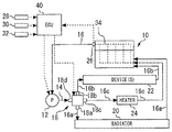
図1は、本発明の実施の形態1の冷媒循環システムの構成を説明するための図である。図1に示すように、本実施の形態の冷媒循環システムは、車両に搭載される内燃機関としてのエンジン10を備えている。エンジン10の本体(シリンダブロックやシリンダヘッド)には、ウォータジャケット34が設けられている。このウォータジャケット34を流れる冷媒(冷却水)とエンジン10との間で熱交換が行われる。
[Description of system configuration]
First,
FIG. 1 is a diagram for explaining a configuration of a refrigerant circulation system according to
ウォータジャケット34を流れる冷媒は、電動式のウォータポンプ12から供給される。ウォータポンプ12は、回転により冷媒を送液するインペラと、このインペラを回転させるモータとを備えている(何れも図示しない)。モータの回転を電気的に制御することで、ウォータポンプ12から吐出される冷媒の流量や吐出圧が変更される。
The refrigerant flowing through the
ウォータジャケット34の入口部とウォータポンプ12の吐出ポート(図示しない)とは、供給流路14によって接続されている。ウォータジャケット34の出口部には、戻り流路16が接続されている。戻り流路16は途中で3つの流路16a〜16cに分岐している。分岐流路16a〜16cは、独立してウォータポンプ12の吸入ポート(図示しない)に接続されている。つまり、本実施の形態の冷媒循環システムは、供給流路14、ウォータジャケット34および戻り流路16が共通し、分岐流路16a〜16cが独立する3つの冷媒循環流路を備えている。
The inlet portion of the
第1の循環流路は、分岐流路16aに設けられたラジエータ20に冷媒を通過させるものである。ラジエータ20に冷媒を通過させると、外気と冷媒との間で熱交換が行われる。第2の循環流路は、分岐流路16bに設けられたデバイス22に冷媒を通過させるものである。デバイス22には、オイルクーラ、EGRクーラ、ATF(自動変速機油)クーラ等が含まれている。デバイス22に冷媒を通過させると、デバイス22を流れる流体(オイル、EGRガス等)と冷媒との間で熱交換が行われる。第3の循環流路は、分岐流路16cに設けられた車内空調用のヒータ24に冷媒を通過させるものである。ヒータ24に冷媒を通過させると車内暖房用空気と冷媒との間で熱交換が行われる。
The first circulation channel allows the refrigerant to pass through the
第1〜第3の循環流路が分岐する部分、即ち、戻り流路16が分岐流路16a〜16cに分岐する部分には、ロータリーバルブ18が設けられている。ロータリーバルブ18は、排出ポート18a〜18cおよび流入ポート18dを有するバルブボディと、バルブボディ内に回転軸を中心に回転自在に収容されたロータと、ロータを回転させるモータと、を備えている(何れも図示しない)。モータによってロータを回転させると、各排出ポートと流入ポート18dとの間の開口面積が変化して、各排出ポートと流入ポート18dとの連通状態が変化する。つまり、各分岐流路の開口面積が変化して各分岐流路の開閉状態が変化する。ロータリーバルブ18によれば、各分岐流路に流す冷媒の流量、各分岐流路の熱交換器への熱の分配や、冷媒循環システム内を循環させる冷媒の温度を制御できる。
A
本実施の形態の冷媒循環システムは、更に、ECU(Electronic Control Unit)40を備えている。ECU40は、少なくとも入出力インタフェースとメモリとCPUとを備えている。入出力インタフェースは、各種センサからセンサ信号を取り込むとともに、アクチュエータに対して操作信号を出力するために設けられる。ECU40が信号を取り込むセンサには、ウォータジャケット34の出口部に設けられた温度センサ26、エンジン10の回転速度を検出するためのクランク角センサ28、スロットルバルブ(図示しない)の開度を検出するための開度センサ30、車内空調のON/OFFを切り替えるスイッチ32等が含まれる。ECU40が操作信号を出すアクチュエータには、上述したウォータポンプ12のモータや、ロータリーバルブ18のモータが含まれる。メモリには、後述する開度スケジュールを定めた制御プログラム、各種マップ等が記憶されている。CPUは、制御プログラム等をメモリから読み出して実行し、取り込んだセンサ信号に基づいて操作信号を生成する。
The refrigerant circulation system of the present embodiment further includes an ECU (Electronic Control Unit) 40. The
[実施の形態1の特徴]
上述したように、ロータリーバルブ18によれば、デバイス22に冷媒を通過させてこの冷媒とデバイス22を流れる流体との間で熱交換できるので、エンジンオイルやEGRガスを冷却して燃費を向上できる。また、ヒータ24に冷媒を通過させてこの冷媒と車内暖房用空気との間で熱交換できるので、車内空気を温め、或いは、クーラ使用時の車内温度を調節できる。このような観点から、本発明者は、燃費と空調性能の両立を図るべく、ロータリーバルブ18のロータの基準位置からの回転角度(以下、「ロータの回転角度」と称す)に関連付けて定めた当該ロータの動作計画に基づいて、各分岐流路の開閉状態を制御することを検討しているところである。この動作計画について、図2を参照しながら説明する。
[Features of Embodiment 1]
As described above, according to the
図2は、ロータリーバルブ18のロータの動作計画を示す図である。図2の横軸がロータの回転角度を示し、縦軸が各分岐流路の開閉状態の変化を示している。この動作計画は、ヒータ24に冷媒を通過させる要求(以下、「ヒータ要求」と称す)がある場合に使用される通常モードと、ヒータ要求がない場合に使用されるヒータカットモードとから構成される。通常モードとヒータカットモードは、全ての分岐流路が閉じられて、全ての分岐流路に流す冷媒の流量がゼロとなる領域(領域d)を隔てている。
FIG. 2 is a diagram showing an operation plan of the rotor of the
通常モードでは、ヒータ24への冷媒の通水が最優先される。図2において、領域dから右に進む方向にロータを回転させると、ロータの回転角度が領域dの隣の領域(領域c)に移行する。領域cでは分岐流路16cが開き始め、ヒータ24に冷媒が通過し始める。ここから更にロータを回転させると、分岐流路16cが完全に開き、ロータの回転角度が領域cの隣の領域(領域b)に移行する。領域bでは分岐流路16bが開き始め、デバイス22に冷媒が通過し始める。ここから更にロータを回転させると、分岐流路16bが完全に開き、ロータの回転角度が領域bの隣の領域(領域a)に移行する。領域aでは分岐流路16aが開き始め、ラジエータ20に冷媒が通過し始める。ここから更にロータを回転させると、分岐流路16aが完全に開く。なお、分岐流路16aが完全に開かれるロータの回転角度の位置がロータの回転限界(Rotation limit)に相当し、この回転限界を上述の基準位置として動作計画が策定されている。
In the normal mode, the highest priority is given to water flow of the refrigerant to the
ヒータカットモードでは、ヒータ24への冷媒の通水は行われず、ラジエータ20よりもデバイス22への冷媒の通水が優先される。図2において、領域dから左に進む方向にロータを回転させると、領域dの隣の領域(領域e)に移行する。領域eでは分岐流路16bが開き始め、デバイス22に冷媒が通過し始める。ここから更にロータを回転させると、分岐流路16bが完全に開き、ロータの回転角度が領域eの隣の領域(領域f)に移行する。領域fでは分岐流路16bのみが開き、デバイス22にのみ冷媒が通過する。ここから更にロータを回転させると、ロータの回転角度が領域fの隣の領域(領域g)に移行する。領域gでは分岐流路16aが開き始め、ラジエータ20に冷媒が通過し始める。ここから更にロータを回転させると、分岐流路16aが完全に開く。
In the heater cut mode, the coolant does not flow to the
図2に示した動作計画によれば、燃費と空調性能の両立を図ることが可能となる。しかしながら、この動作計画を用いた場合、モードの切り替えが行われる場合に次のような問題があることが明らかとなった。即ち、運転者によってスイッチ32がONに操作された場合には、ヒータ要求が出されてヒータカットモードから通常モードへとモード切り替えが行われる。例えば、ロータの回転角度が領域eにあるときにヒータ要求があると、ロータを回転させてロータの回転角度が領域cに移行させられる。また、運転者によってスイッチ32がONからOFFへと操作された場合には、ヒータ要求が終了され通常モードからヒータカットモードへとモード切り替えが行われる。例えば、ロータの回転角度が領域cにあるときにヒータ要求が終了すると、ロータを回転させてロータの回転角度が領域eに移行させられる。
According to the operation plan shown in FIG. 2, it is possible to achieve both fuel efficiency and air conditioning performance. However, when this operation plan is used, it has become clear that there are the following problems when the mode is switched. In other words, when the
ここで、ロータの回転角度を領域eから領域cへ、または、領域cから領域eへと移行させるためには、領域dを経由しなければならない。領域eと領域cの間の移行は短時間で完了するので、領域dを経由する時間も僅かである。しかしながら、冷媒が高温である場合は、冷媒が冷却されず沸騰するおそれがあることから、短時間であったとしても領域dを経由するのはエンジンの信頼性を確保する観点から望ましくない。そこで、本実施の形態では、通常モードとヒータカットモードとを切り替える要求(以下、「モード切り替え要求」と称す)が出された場合に、モードの切り替えの許可/不許可を判定することとしている。 Here, in order to shift the rotation angle of the rotor from the region e to the region c or from the region c to the region e, the rotor must pass through the region d. Since the transition between the region e and the region c is completed in a short time, the time passing through the region d is also short. However, when the refrigerant is at a high temperature, the refrigerant may be boiled without being cooled. Therefore, even if the refrigerant is used for a short time, it is not desirable from the viewpoint of securing the reliability of the engine. Therefore, in this embodiment, when a request for switching between the normal mode and the heater cut mode (hereinafter referred to as “mode switching request”) is issued, permission / non-permission of mode switching is determined. .
モード切り替えの許可/不許可の判定は、具体的に、温度センサ26で検出された冷媒の温度と、冷媒の上限温度との比較により行われる。図3は、モードの切り替えの許可/不許可を判定する際に使用する冷媒の上限温度を説明するための図である。図3に示すように、冷媒の上限温度はエンジンの運転状態(負荷および回転速度)に基づいて設定されており、この設定領域は負荷や回転速度が高くなるほど拡大している。また、冷媒の上限温度は2つ設定されている。低負荷時は高負荷時に比べて冷媒の受熱量が少ないので冷媒が沸騰しにくくなる。そこで、図3に示すように、上限温度の設定領域のうちの低負荷領域の一部に、冷媒の上限温度を他に比べて高くする領域を設けている(低水温TL<高水温TH)。なお、図3に示した2つの上限温度とエンジンの運転状態との関係は、制御マップの形式でECU40のメモリに記憶されているものとする。
Specifically, the determination as to whether mode switching is permitted / not permitted is made by comparing the refrigerant temperature detected by the
本実施の形態によれば、図3に示した関係に基づいて、モードの切り替えの許可/不許可を判定することができる。そのため、モードの切り替えが不許可とされた場合に、モード切り替え要求に従ったロータの回転が禁止されて、ロータの回転角度が図2の領域dに移行するのを中止できる。従って、モードの切り替え時に冷媒が沸騰するのを回避できる。よって、冷媒の沸騰に伴うエンジン部品の損傷等を未然に防止できる。 According to the present embodiment, permission / non-permission of mode switching can be determined based on the relationship shown in FIG. Therefore, when the mode switching is not permitted, the rotation of the rotor according to the mode switching request is prohibited and the rotation angle of the rotor can be stopped from shifting to the region d in FIG. Therefore, it is possible to avoid boiling of the refrigerant when the mode is switched. Therefore, it is possible to prevent engine parts from being damaged due to boiling of the refrigerant.
[具体的処理]
次に、図4を参照しながら、上述した機能を実現するための具体的な処理について説明する。図4は、実施の形態1において、ECU40により実行されるモード切り替え判定ルーチンを示すフローチャートである。なお、図4に示すルーチンは、エンジン10の始動直後から所定の制御周期ごとに繰り返し実行されるものとする。
[Specific processing]
Next, specific processing for realizing the above-described functions will be described with reference to FIG. FIG. 4 is a flowchart showing a mode switching determination routine executed by
図4に示すルーチンでは、先ず、モード切り替え要求の有無が判定される(ステップS10)。モード切り替え要求の有無は、スイッチ32の切り替え操作の有無に基づいて判定される。モード切り替え要求が無いと判定された場合には、本ルーチンを終了する。
In the routine shown in FIG. 4, first, it is determined whether or not there is a mode switching request (step S10). The presence / absence of a mode switching request is determined based on the presence / absence of a switching operation of the
ステップS10において、モード切り替え要求が有ると判定された場合には、エンジン10の回転速度と負荷が検出される(ステップS12)。本ステップにおいて、エンジン10の回転速度は、クランク角センサ28の出力信号に基づき検出され、エンジン10の負荷は開度センサ30の出力信号に基づき検出される。
If it is determined in step S10 that there is a mode switching request, the rotational speed and load of the
ステップS12に続き、冷媒の温度が規定値以下か否かが判定される(ステップS14)。本ステップでは、先ず、温度センサ26の出力信号に基づいて冷媒の温度が検出される。続いて、この検出された冷媒温度と規定値とが比較される。当該規定値は、ステップS14で検出されたエンジン10の回転速度と負荷と、図3の関係を表した制御マップとに基づいて決定された上限温度である(つまり、低水温TLまたは高水温TH)。
Following step S12, it is determined whether the temperature of the refrigerant is equal to or lower than a specified value (step S14). In this step, first, the temperature of the refrigerant is detected based on the output signal of the
ステップS14において、冷媒の温度が規定値以下であると判定された場合には、モードを切り替えたとしても冷媒が沸騰する可能性は低いと判断できる。そのため、モードの切り替えが許可される(ステップS16)。これにより、ロータの回転角度が変更されてモードの切り替えが実行される。一方、ステップS14において、冷媒の温度が規定値よりも高いと判定された場合には、モードの切り替えに伴い冷媒が沸騰する可能性が高いと判断できる。そのため、モードの切り替えが不許可とされる(ステップS18)。これにより、モード切り替え要求に従ったロータの回転が禁止される。 If it is determined in step S14 that the temperature of the refrigerant is equal to or lower than the specified value, it can be determined that the possibility that the refrigerant will boil is low even if the mode is switched. Therefore, mode switching is permitted (step S16). Thereby, the rotation angle of the rotor is changed, and the mode is switched. On the other hand, if it is determined in step S14 that the temperature of the refrigerant is higher than the specified value, it can be determined that there is a high possibility that the refrigerant will boil as the mode is switched. Therefore, mode switching is not permitted (step S18). Thereby, the rotation of the rotor according to the mode switching request is prohibited.
以上、図4に示したルーチンによれば、モードの切り替え時に冷媒が沸騰するのを回避できる。従って、冷媒の沸騰に伴うエンジン部品の損傷等を未然に防止できる。 As described above, according to the routine shown in FIG. 4, it is possible to avoid boiling of the refrigerant when the mode is switched. Therefore, it is possible to prevent damage to engine components and the like due to boiling of the refrigerant.
なお、上記実施の形態1においては、戻り流路16、分岐流路16aおよび供給流路14または戻り流路16、分岐流路16bおよび供給流路14が上記第1の発明における「第1冷媒回路」に、分岐流路16cおよび供給流路14が同発明における「第2冷媒回路」に、ラジエータ20またはデバイス22が同発明における「第1熱交換器」に、ヒータ24が同発明における「第2熱交換器」に、ロータリーバルブ18が同発明の「制御弁」に、ECU40が同発明の「制御手段」に、通常モードが同発明の「全通モード」に、ヒータカットモードが同発明の「部分遮断モード」に、図2の領域a,b,cが同発明の「全通モードに対応する回転角度域」に、図2の領域e,f,gが同発明の「部分遮断モードに対応する回転角度域」に、図2の領域dが同発明の「第1冷媒回路および第2冷媒回路の両方が閉じた状態とされる回転角度域」に、それぞれ相当している。
In the first embodiment, the
ところで、上記実施の形態1においては、ロータリーバルブ18を使用する例を説明したが、例えばボールバルブ等、回転軸を中心としたロータの回転によって各分岐流路の開閉状態を変えることが可能なバルブであれば、ロータリーバルブ18の代わりに使用できる。なお、本変形例は、後述する実施の形態2においても同様に適用できる。
In the first embodiment, the example in which the
また、上記実施の形態1においては、戻り流路16の下流において分岐流路16a〜16cに分岐させ、この分岐部にロータリーバルブ18を設けた。しかし、本発明は、図5に示す冷媒循環システムにも適用できる。図5は、実施の形態1の冷媒循環システムの変形例を説明するための図である。この冷媒循環システムでは、供給流路14の下流において分岐流路16a〜16cが分岐している。分岐流路16a〜16cは、独立してウォータジャケット34に接続されている。また、ロータリーバルブ18は、供給流路14が分岐流路16a〜16cに分岐する部分に設けられている。このようなシステムであっても、図2に示した動作計画に基づいて、各分岐流路の開閉状態を制御できる。なお、本変形例は、後述する実施の形態2においても同様に適用できる。
Moreover, in the said
実施の形態2.
次に、図6を参照しながら、本発明の実施の形態2について説明する。なお、本実施の形態においては、上記実施の形態1の冷媒循環システムおよび動作計画を前提とするため、これらの説明は省略する。
Embodiment 2. FIG.
Next, Embodiment 2 of the present invention will be described with reference to FIG. In addition, in this Embodiment, since the refrigerant | coolant circulation system and operation plan of the said
[実施の形態2の特徴]
上記実施の形態1では、冷媒の温度が上限温度よりも高いと判定された場合には、モードの切り替えが不許可とされた。但し、分岐流路16a〜16cの何れかと戻り流路16が連通していれば冷媒は冷やされるので、温度センサ26で検出される冷媒の温度は次第に低下する。従って、モード切り替え要求が出された際に、モードの切り替えが不許可され続けるということはなく、モード切り替え要求に応答するためには、冷媒の温度が上限温度以下となるまで待機すればよい。しかし、この待機時間が長くなれば、それだけモード切り替え要求に対応できない状況が続くことになるので望ましくない。そこで、本実施の形態では、この待機時間が長くなった場合には、排出ポート18aと流入ポート18dとの間の開口面積(つまり、分岐流路16aと戻り流路16との間の開口面積)を増加させるようにロータを回転させることとしている。
[Features of Embodiment 2]
In the first embodiment, when it is determined that the temperature of the refrigerant is higher than the upper limit temperature, the mode switching is not permitted. However, since the refrigerant is cooled if any of the
分岐流路16aと戻り流路16との間の開口面積を増加させれば、ラジエータ20により多くの冷媒を通過させることができる。従って、外気と冷媒との間で熱交換を行わせて冷媒の温度を冷やし、短時間で上限温度以下まで低下させることができる。
If the opening area between the
但し、モードの切り替え自体は不許可とされているので、分岐流路16aと戻り流路16との間の開口面積を増加させるためのロータの回転は、モード切り替え要求が出された際のモード内において行われる。例えば、モード切り替え要求時にロータの回転角度が図2の領域eにあった場合には、領域eと同一のモード内、即ち、ヒータカットモード内の領域gに移行させるようにロータを回転させる。また、モード切り替え要求時にロータの回転角度が図2の領域cにあった場合には、領域cと同一のモード内、即ち、通常モード内の領域aに移行させるようにロータを回転させる。
However, since the mode switching itself is not permitted, the rotation of the rotor for increasing the opening area between the
また、例えば、モード切り替え要求時にロータの回転角度が図2の領域gにあった場合には、当該領域g内において分岐流路16aと戻り流路16との間の開口面積をより増加させる方向(図2において領域gのより左側の方向)にロータを回転させる。また、モード切り替え要求時にロータの回転角度が図2の領域aにあった場合には、当該領域a内において分岐流路16aと戻り流路16との間の開口面積をより増加させる方向(図2において領域aのより右側の方向)にロータを回転させる。
Further, for example, when the rotation angle of the rotor is in the region g in FIG. 2 when the mode switching request is made, the direction in which the opening area between the
[具体的処理]
次に、図6を参照しながら、上述した機能を実現するための具体的な処理について説明する。図6は、実施の形態2において、ECU40により実行されるモード切り替え判定ルーチンを示すフローチャートである。なお、図6に示すルーチンは、エンジン10の始動直後から所定の制御周期ごとに繰り返し実行されるものとする。
[Specific processing]
Next, specific processing for realizing the above-described function will be described with reference to FIG. FIG. 6 is a flowchart showing a mode switching determination routine executed by
図6に示すルーチンでは、先ず、モード切り替え要求の有無が判定される(ステップS20)。本ステップの処理は図4のステップS10の処理と同一である。 In the routine shown in FIG. 6, first, the presence / absence of a mode switching request is determined (step S20). The processing in this step is the same as the processing in step S10 in FIG.
ステップS20において、モード切り替え要求が有ると判定された場合には、モード切り替え要求が出された時点からの経過時間のカウントが開始され(ステップS22)、エンジン10の回転速度と負荷が検出される(ステップS24)。ステップS24の処理は図4のステップS12の処理と同一である。
In step S20, when it is determined that there is a mode switching request, counting of elapsed time from the time when the mode switching request is issued is started (step S22), and the rotation speed and load of the
ステップS24に続き、冷媒の温度が規定値以下か否かが判定される(ステップS26)。本ステップの処理は図4のステップS14の処理と同一である。ステップS26において、冷媒の温度が規定値以下であると判定された場合には、モードを切り替えたとしても冷媒が沸騰する可能性は低いと判断できる。そのため、モードの切り替えが行われる(ステップS28)。 Following step S24, it is determined whether the temperature of the refrigerant is equal to or lower than a specified value (step S26). The processing in this step is the same as the processing in step S14 in FIG. If it is determined in step S26 that the temperature of the refrigerant is equal to or lower than the specified value, it can be determined that the possibility that the refrigerant will boil is low even if the mode is switched. Therefore, the mode is switched (step S28).
ステップS26において、冷媒の温度が規定値よりも高いと判定された場合には、経過時間が規定値以上か否かが判定される(ステップS30)。本ステップにおいて用いられる規定値は、許容経過時間として予め定められECU40内に記憶されているものとする。経過時間が規定値よりも短いと判定された場合には、ステップS24に戻り、エンジン10の回転速度と負荷が検出される。経過時間が規定値以上であると判定された場合には、分岐流路16aと戻り流路16との間の開口面積を増加させるようにロータを回転させる(ステップS32)。最後に経過時間のカウントをリセットして(ステップS34)、本ルーチンを閉じる。
If it is determined in step S26 that the refrigerant temperature is higher than the specified value, it is determined whether the elapsed time is equal to or greater than the specified value (step S30). The specified value used in this step is determined in advance as the allowable elapsed time and stored in the
以上、図6に示したルーチンによれば、モード切り替え要求が出された時点からの経過時間が規定値以上となった場合に、分岐流路16aと戻り流路16との間の開口面積を増加させることができる。即ち、このような場合に冷媒の温度を短時間で低下させて、モード切り替え要求に対応できない状況を早期に解消できる。
As described above, according to the routine shown in FIG. 6, the opening area between the
なお、上記実施の形態2においては、戻り流路16、分岐流路16aおよび供給流路14が上記第2の発明における「第1冷媒回路」に相当している。
In the second embodiment, the
10 エンジン
14 供給流路
16 戻り流路
16a〜16c 分岐流路
20 ラジエータ
22 デバイス
24 ヒータ
26 温度センサ
28 クランク角センサ
30 スロットルバルブ開度センサ
32 スイッチ
34 ウォータジャケット
40 ECU
DESCRIPTION OF
Claims (2)
前記第1冷媒回路に設けられ、回転軸を中心に回転自在なロータを備える制御弁と、
前記制御弁に接続され、前記本体を通過した冷媒を第2熱交換器と熱交換させた後に前記本体に戻すための第2冷媒回路と、
前記第1冷媒回路および前記第2冷媒回路の開閉状態を前記ロータの基準位置からの回転角度に関連付けて定めた動作計画に基づいて、前記ロータの回転動作を制御する制御手段と、
を備え、
前記動作計画は、前記第1冷媒回路および前記第2冷媒回路の両方を閉じた状態から開いた状態まで変化させる全通モードと、前記第1冷媒回路と前記第2冷媒回路の両方を閉じた状態から前記第1冷媒回路のみを開いた状態まで変化させる部分遮断モードと、を備え、前記動作計画の前記全通モードに対応する回転角度域と、前記部分遮断モードに対応する回転角度域とは、前記第1冷媒回路と前記第2冷媒回路の両方が閉じた状態とされる回転角度域を隔てており、
前記制御手段は、前記第1冷媒回路と前記第2冷媒回路の両方が閉じた状態とされる回転角度域を経由する、前記全通モードと前記部分遮断モードとを切り替えるモード切り替え要求が出された場合において、前記内燃機関の運転状態に基づいて決定される冷媒の上限温度よりも前記本体を通過した冷媒の温度の方が高いときは、前記全通モードと前記部分遮断モードの切り替えを禁止することを特徴とする冷媒循環システム。 A first refrigerant circuit for returning the refrigerant that has passed through the main body of the internal combustion engine to the main body after exchanging heat with the first heat exchanger;
A control valve provided in the first refrigerant circuit and including a rotor rotatable around a rotation axis;
A second refrigerant circuit connected to the control valve for returning the refrigerant that has passed through the main body to the main body after exchanging heat with the second heat exchanger;
Control means for controlling the rotational operation of the rotor based on an operation plan in which the open / closed states of the first refrigerant circuit and the second refrigerant circuit are associated with the rotation angle from the reference position of the rotor;
With
The operation plan, and Zentsu mode changing to the state had state or RaHiraku which close both the first refrigerant circuit and the second refrigerant circuit, close both the first refrigerant circuit and the second refrigerant circuit A partial cut-off mode in which only the first refrigerant circuit is changed to an open state, and a rotation angle range corresponding to the full-pass mode of the operation plan and a rotation angle range corresponding to the partial cut-off mode Is separated from a rotation angle range in which both the first refrigerant circuit and the second refrigerant circuit are closed,
The control means issues a mode switching request for switching between the full- pass mode and the partial cut-off mode via a rotation angle range in which both the first refrigerant circuit and the second refrigerant circuit are closed. When the temperature of the refrigerant that has passed through the main body is higher than the upper limit temperature of the refrigerant determined based on the operating state of the internal combustion engine , switching between the full- pass mode and the partial cutoff mode is prohibited A refrigerant circulation system.
前記第1熱交換器は、外気との熱交換により冷媒を冷却可能なラジエータであり、
前記制御手段は、前記全通モードと前記部分遮断モードの切り替えを禁止した場合において、前記モード切り替え要求が出されてからの経過時間が所定時間を上回るときは、前記第1冷媒回路の開口面積が増加する方向に前記ロータを回転させることを特徴とする請求項1に記載の冷媒循環システム。 The control valve is configured to be able to change an opening area of the first refrigerant circuit and an opening area of the second refrigerant circuit by rotation of the rotor,
The first heat exchanger is a radiator capable of cooling the refrigerant by exchanging heat with outside air,
In the case where switching between the full mode and the partial cut-off mode is prohibited, when the elapsed time from the mode switching request exceeds a predetermined time, the control means opens the opening area of the first refrigerant circuit The refrigerant circulation system according to claim 1, wherein the rotor is rotated in a direction in which the value of the refrigerant increases.
Priority Applications (4)
| Application Number | Priority Date | Filing Date | Title |
|---|---|---|---|
| JP2014206326A JP6032255B2 (en) | 2014-10-07 | 2014-10-07 | Refrigerant circulation system |
| CN201510614088.0A CN105484851B (en) | 2014-10-07 | 2015-09-23 | Refrigerant-cycle systems |
| US14/874,732 US9758017B2 (en) | 2014-10-07 | 2015-10-05 | Refrigerant circulation system |
| EP15188466.5A EP3009627B1 (en) | 2014-10-07 | 2015-10-06 | Refrigerant circulation system |
Applications Claiming Priority (1)
| Application Number | Priority Date | Filing Date | Title |
|---|---|---|---|
| JP2014206326A JP6032255B2 (en) | 2014-10-07 | 2014-10-07 | Refrigerant circulation system |
Publications (2)
| Publication Number | Publication Date |
|---|---|
| JP2016075225A JP2016075225A (en) | 2016-05-12 |
| JP6032255B2 true JP6032255B2 (en) | 2016-11-24 |
Family
ID=54291094
Family Applications (1)
| Application Number | Title | Priority Date | Filing Date |
|---|---|---|---|
| JP2014206326A Active JP6032255B2 (en) | 2014-10-07 | 2014-10-07 | Refrigerant circulation system |
Country Status (4)
| Country | Link |
|---|---|
| US (1) | US9758017B2 (en) |
| EP (1) | EP3009627B1 (en) |
| JP (1) | JP6032255B2 (en) |
| CN (1) | CN105484851B (en) |
Cited By (1)
| Publication number | Priority date | Publication date | Assignee | Title |
|---|---|---|---|---|
| KR20220095377A (en) * | 2020-12-29 | 2022-07-07 | 엠에이치기술개발 주식회사 | Cooling system having multiple cooling units |
Families Citing this family (6)
| Publication number | Priority date | Publication date | Assignee | Title |
|---|---|---|---|---|
| JP6493146B2 (en) * | 2015-10-19 | 2019-04-03 | 株式会社デンソー | Valve control device |
| CN106979061B (en) * | 2017-03-30 | 2019-11-05 | 广州汽车集团股份有限公司 | A kind of electronic water pump for engine control method and system |
| US11285778B2 (en) * | 2017-06-14 | 2022-03-29 | Denso Corporation | Valve device |
| US20190024569A1 (en) * | 2017-07-18 | 2019-01-24 | GM Global Technology Operations LLC | Adjusting a flow control valve during a mode change of a main rotary valve in a vehicle cooling system |
| KR102478096B1 (en) * | 2017-12-19 | 2022-12-19 | 현대자동차주식회사 | Flow control valve |
| JP7434814B2 (en) * | 2019-11-07 | 2024-02-21 | 株式会社デンソー | valve device |
Family Cites Families (11)
| Publication number | Priority date | Publication date | Assignee | Title |
|---|---|---|---|---|
| JPH10131753A (en) | 1996-10-30 | 1998-05-19 | Denso Corp | Cooling device for water-cooled engine |
| JP3552543B2 (en) * | 1998-07-29 | 2004-08-11 | 株式会社デンソー | Cooling system for liquid-cooled internal combustion engine |
| JP4337207B2 (en) * | 2000-02-10 | 2009-09-30 | 株式会社デンソー | Cooling device for liquid-cooled internal combustion engine |
| FR2827359B1 (en) * | 2001-07-11 | 2004-11-05 | Valeo Thermique Moteur Sa | CONTROL VALVE FOR A COOLING CIRCUIT OF A MOTOR VEHICLE HEAT ENGINE |
| US6681805B2 (en) * | 2001-11-28 | 2004-01-27 | Ranco Incorporated Of Delaware | Automotive coolant control valve |
| US6539899B1 (en) * | 2002-02-11 | 2003-04-01 | Visteon Global Technologies, Inc. | Rotary valve for single-point coolant diversion in engine cooling system |
| JP2003247421A (en) * | 2002-02-21 | 2003-09-05 | Toyota Motor Corp | Cooling device of engine |
| JP4151445B2 (en) | 2003-03-24 | 2008-09-17 | トヨタ自動車株式会社 | Engine cooling system |
| JP4631652B2 (en) * | 2005-10-25 | 2011-02-16 | トヨタ自動車株式会社 | COOLING SYSTEM, ITS CONTROL METHOD, AND AUTOMOBILE |
| JP5505331B2 (en) * | 2011-02-23 | 2014-05-28 | 株式会社デンソー | Internal combustion engine cooling system |
| JP5974619B2 (en) | 2012-05-09 | 2016-08-23 | 日産自動車株式会社 | Control device and control method for engine cooling system |
-
2014
- 2014-10-07 JP JP2014206326A patent/JP6032255B2/en active Active
-
2015
- 2015-09-23 CN CN201510614088.0A patent/CN105484851B/en not_active Expired - Fee Related
- 2015-10-05 US US14/874,732 patent/US9758017B2/en active Active
- 2015-10-06 EP EP15188466.5A patent/EP3009627B1/en active Active
Cited By (3)
| Publication number | Priority date | Publication date | Assignee | Title |
|---|---|---|---|---|
| KR20220095377A (en) * | 2020-12-29 | 2022-07-07 | 엠에이치기술개발 주식회사 | Cooling system having multiple cooling units |
| KR102439282B1 (en) * | 2020-12-29 | 2022-09-05 | 엠에이치기술개발 주식회사 | Cooling system having multiple cooling units |
| US11913702B2 (en) | 2020-12-29 | 2024-02-27 | Mh Technologies Inc. | Cooling system including a plurality of cooling units |
Also Published As
| Publication number | Publication date |
|---|---|
| CN105484851A (en) | 2016-04-13 |
| EP3009627A1 (en) | 2016-04-20 |
| JP2016075225A (en) | 2016-05-12 |
| CN105484851B (en) | 2018-08-24 |
| US20160096414A1 (en) | 2016-04-07 |
| US9758017B2 (en) | 2017-09-12 |
| EP3009627B1 (en) | 2018-05-16 |
Similar Documents
| Publication | Publication Date | Title |
|---|---|---|
| JP6032255B2 (en) | Refrigerant circulation system | |
| JP6330748B2 (en) | Cooling device for internal combustion engine | |
| JP6330768B2 (en) | Engine cooling system | |
| EP3109430B1 (en) | Internal combustion engine with cooling apparatus | |
| JP6264348B2 (en) | Engine cooling system | |
| JP4196802B2 (en) | Cooling water circuit | |
| JP5754503B2 (en) | Fluid control system | |
| JP5699839B2 (en) | Engine cooling system | |
| JP6024822B2 (en) | Cooling water control device | |
| WO2018225337A1 (en) | Device and method for cooling internal combustion engine | |
| JP2008051019A (en) | Exhaust heat recovery device for internal combustion engine | |
| JP6413835B2 (en) | Cooling device for internal combustion engine | |
| JP2016210298A (en) | Cooling device of internal combustion engine | |
| JP2016056760A (en) | Engine cooling device | |
| JP2016151215A (en) | Cooling device for internal combustion engine | |
| JP2018080608A (en) | Cooling system | |
| JP2012241609A (en) | Fluid control system | |
| JP2016151205A (en) | Cooling water circulation system | |
| JP2016151218A (en) | Cooling device for internal combustion engine | |
| JP2017057806A (en) | Control device for engine cooling system | |
| JP2020056356A (en) | Vehicle control device | |
| JP2010248942A (en) | Control device for internal combustion engine | |
| JP2017048682A (en) | Engine cooling device |
Legal Events
| Date | Code | Title | Description |
|---|---|---|---|
| A131 | Notification of reasons for refusal |
Free format text: JAPANESE INTERMEDIATE CODE: A131 Effective date: 20160607 |
|
| A521 | Request for written amendment filed |
Free format text: JAPANESE INTERMEDIATE CODE: A523 Effective date: 20160801 |
|
| TRDD | Decision of grant or rejection written | ||
| A01 | Written decision to grant a patent or to grant a registration (utility model) |
Free format text: JAPANESE INTERMEDIATE CODE: A01 Effective date: 20160927 |
|
| A61 | First payment of annual fees (during grant procedure) |
Free format text: JAPANESE INTERMEDIATE CODE: A61 Effective date: 20161010 |
|
| R151 | Written notification of patent or utility model registration |
Ref document number: 6032255 Country of ref document: JP Free format text: JAPANESE INTERMEDIATE CODE: R151 |