JP6031373B2 - Optical component fixing structure, optical component fixing method, optical pickup device manufacturing method, and RGB three primary color light source module device manufacturing method - Google Patents
Optical component fixing structure, optical component fixing method, optical pickup device manufacturing method, and RGB three primary color light source module device manufacturing method Download PDFInfo
- Publication number
- JP6031373B2 JP6031373B2 JP2013025391A JP2013025391A JP6031373B2 JP 6031373 B2 JP6031373 B2 JP 6031373B2 JP 2013025391 A JP2013025391 A JP 2013025391A JP 2013025391 A JP2013025391 A JP 2013025391A JP 6031373 B2 JP6031373 B2 JP 6031373B2
- Authority
- JP
- Japan
- Prior art keywords
- holder
- plate portion
- optical component
- housing
- hole
- Prior art date
- Legal status (The legal status is an assumption and is not a legal conclusion. Google has not performed a legal analysis and makes no representation as to the accuracy of the status listed.)
- Expired - Fee Related
Links
- 230000003287 optical effect Effects 0.000 title claims description 140
- 238000000034 method Methods 0.000 title claims description 22
- 238000004519 manufacturing process Methods 0.000 title claims 6
- 239000000853 adhesive Substances 0.000 claims description 91
- 230000001070 adhesive effect Effects 0.000 claims description 91
- 229920005989 resin Polymers 0.000 claims description 9
- 239000011347 resin Substances 0.000 claims description 9
- 230000015572 biosynthetic process Effects 0.000 claims description 7
- 238000003786 synthesis reaction Methods 0.000 claims description 7
- 230000001678 irradiating effect Effects 0.000 claims description 5
- 239000003086 colorant Substances 0.000 claims 1
- 230000008602 contraction Effects 0.000 description 10
- 238000003848 UV Light-Curing Methods 0.000 description 9
- 238000003825 pressing Methods 0.000 description 9
- 230000000694 effects Effects 0.000 description 8
- 238000012360 testing method Methods 0.000 description 7
- 230000017525 heat dissipation Effects 0.000 description 5
- 238000009281 ultraviolet germicidal irradiation Methods 0.000 description 5
- 238000001723 curing Methods 0.000 description 4
- 238000006073 displacement reaction Methods 0.000 description 4
- 239000000463 material Substances 0.000 description 3
- 239000011248 coating agent Substances 0.000 description 2
- 238000000576 coating method Methods 0.000 description 2
- 150000002484 inorganic compounds Chemical class 0.000 description 2
- 229910010272 inorganic material Inorganic materials 0.000 description 2
- 239000007788 liquid Substances 0.000 description 2
- 239000002184 metal Substances 0.000 description 2
- 229910052751 metal Inorganic materials 0.000 description 2
- 230000035515 penetration Effects 0.000 description 2
- 239000000843 powder Substances 0.000 description 2
- 239000003522 acrylic cement Substances 0.000 description 1
- 239000002131 composite material Substances 0.000 description 1
- 230000007423 decrease Effects 0.000 description 1
- 229920006332 epoxy adhesive Polymers 0.000 description 1
- 239000011521 glass Substances 0.000 description 1
- 239000007787 solid Substances 0.000 description 1
- 229910052725 zinc Inorganic materials 0.000 description 1
Images


Classifications
-
- F—MECHANICAL ENGINEERING; LIGHTING; HEATING; WEAPONS; BLASTING
- F16—ENGINEERING ELEMENTS AND UNITS; GENERAL MEASURES FOR PRODUCING AND MAINTAINING EFFECTIVE FUNCTIONING OF MACHINES OR INSTALLATIONS; THERMAL INSULATION IN GENERAL
- F16B—DEVICES FOR FASTENING OR SECURING CONSTRUCTIONAL ELEMENTS OR MACHINE PARTS TOGETHER, e.g. NAILS, BOLTS, CIRCLIPS, CLAMPS, CLIPS OR WEDGES; JOINTS OR JOINTING
- F16B47/00—Suction cups for attaching purposes; Equivalent means using adhesives
- F16B47/003—Suction cups for attaching purposes; Equivalent means using adhesives using adhesives for attaching purposes
-
- G—PHYSICS
- G11—INFORMATION STORAGE
- G11B—INFORMATION STORAGE BASED ON RELATIVE MOVEMENT BETWEEN RECORD CARRIER AND TRANSDUCER
- G11B7/00—Recording or reproducing by optical means, e.g. recording using a thermal beam of optical radiation by modifying optical properties or the physical structure, reproducing using an optical beam at lower power by sensing optical properties; Record carriers therefor
- G11B7/08—Disposition or mounting of heads or light sources relatively to record carriers
-
- G—PHYSICS
- G11—INFORMATION STORAGE
- G11B—INFORMATION STORAGE BASED ON RELATIVE MOVEMENT BETWEEN RECORD CARRIER AND TRANSDUCER
- G11B7/00—Recording or reproducing by optical means, e.g. recording using a thermal beam of optical radiation by modifying optical properties or the physical structure, reproducing using an optical beam at lower power by sensing optical properties; Record carriers therefor
- G11B7/12—Heads, e.g. forming of the optical beam spot or modulation of the optical beam
- G11B7/22—Apparatus or processes for the manufacture of optical heads, e.g. assembly
-
- G—PHYSICS
- G11—INFORMATION STORAGE
- G11B—INFORMATION STORAGE BASED ON RELATIVE MOVEMENT BETWEEN RECORD CARRIER AND TRANSDUCER
- G11B7/00—Recording or reproducing by optical means, e.g. recording using a thermal beam of optical radiation by modifying optical properties or the physical structure, reproducing using an optical beam at lower power by sensing optical properties; Record carriers therefor
- G11B7/12—Heads, e.g. forming of the optical beam spot or modulation of the optical beam
- G11B7/125—Optical beam sources therefor, e.g. laser control circuitry specially adapted for optical storage devices; Modulators, e.g. means for controlling the size or intensity of optical spots or optical traces
-
- Y—GENERAL TAGGING OF NEW TECHNOLOGICAL DEVELOPMENTS; GENERAL TAGGING OF CROSS-SECTIONAL TECHNOLOGIES SPANNING OVER SEVERAL SECTIONS OF THE IPC; TECHNICAL SUBJECTS COVERED BY FORMER USPC CROSS-REFERENCE ART COLLECTIONS [XRACs] AND DIGESTS
- Y10—TECHNICAL SUBJECTS COVERED BY FORMER USPC
- Y10T—TECHNICAL SUBJECTS COVERED BY FORMER US CLASSIFICATION
- Y10T403/00—Joints and connections
- Y10T403/47—Molded joint
- Y10T403/472—Molded joint including mechanical interlock
Landscapes
- Engineering & Computer Science (AREA)
- General Engineering & Computer Science (AREA)
- Mechanical Engineering (AREA)
- Physics & Mathematics (AREA)
- Optics & Photonics (AREA)
- Moving Of The Head For Recording And Reproducing By Optical Means (AREA)
- Mounting And Adjusting Of Optical Elements (AREA)
- Optical Head (AREA)
- Optical Couplings Of Light Guides (AREA)
Description
本発明は、CD(コンパクトディスク)、DVD(デジタルバーサタイルディスク)、BD(ブルーレイディスク)等の光ディスクの記録、再生に用いられる光ピックアップ装置及びそれを組み込んだ光ディスクドライブ装置、また、レーザディスプレイに用いられるRGB3原色光源モジュール装置及びそれを組み込んだプロジェクタ装置等に係り、特にレーザダイオード(以下、LD)や受光素子等を代表とする光学部品の接着固定技術に関するものである。 INDUSTRIAL APPLICABILITY The present invention is an optical pickup device used for recording and reproduction of optical discs such as CD (compact disc), DVD (digital versatile disc), and BD (Blu-ray disc), an optical disc drive device incorporating the optical pickup device, and a laser display. In particular, the present invention relates to an adhesive fixing technique for optical components such as a laser diode (hereinafter referred to as LD) and a light receiving element.
本技術分野の背景技術として、国際公開WO2006118037A1(特許文献1)がある。この公報には、「光源を配置する光学基台の上の面に凸部を形成し、光源を保持するホルダと光学基台上の凸部の空隙に硬化型樹脂を塗布することにより、落下衝撃などの外的要因に対して硬化型樹脂のみでも十分な固定強度を得ることができ、また、光源から生じる熱を効率的に基台へ放熱することができる特長」が開示されている。 As a background art in this technical field, there is International Publication WO2006118037A1 (Patent Document 1). In this publication, “a convex portion is formed on the surface of the optical base on which the light source is disposed, and a drop is applied by applying a curable resin to the gap between the holder for holding the light source and the convex portion on the optical base. A feature that a sufficient fixing strength can be obtained with only a curable resin alone against external factors such as impact, and that heat generated from a light source can be efficiently radiated to a base is disclosed.
また、特開2005−32314号公報(特許文献2)がある。この公報には、「発光素子または受光素子を保持する保持部材と光学シャシとの間に位置調整用の隙間を空け、その隙間にUV(紫外線)硬化型の樹脂接着剤で固定する方法において、UVを透過させる無機化合物粉末が混合された接着剤を用いることにより、必要なUV照射量を与えることができ、更に、硬化時の流動変形の抑制により、位置ずれも抑制できる特長」が開示されている。 Moreover, there exists Unexamined-Japanese-Patent No. 2005-32314 (patent document 2). In this publication, “in a method of opening a position adjusting gap between a holding member for holding a light emitting element or a light receiving element and an optical chassis, and fixing the gap with a UV (ultraviolet) curable resin adhesive, By using an adhesive mixed with inorganic compound powder that transmits UV, the necessary UV irradiation amount can be given, and further, the displacement can be suppressed by suppressing the flow deformation at the time of curing. ing.
前記特許文献1には、ホルダと光学基台上の凸部の空隙に硬化型樹脂を塗布することにより、接着剤の接触面積を大きくして、接着強度を高められ、放熱性は向上する。しかし、各空隙への接着剤塗布量のわずかなばらつきにより、サブミクロンオーダの前後左右の位置ずれを抑制する特別の工夫は記載されていない。
In
前記特許文献2には、UVを透過させる無機化合物粉末を混合した接着剤を用いることにより、UV照射量を確保し、接着剤自身の硬化時の位置ずれを抑制できるが、接着剤自身の温度変化時の膨張収縮による位置ずれを防止する方法に関しては、特別の工夫は記載されていない。
In
そこで、本発明では、近年の位置ずれ許容量が厳しい製品にも耐えうるように、接着剤自身の温度変化による膨張収縮を利用し、組立時及び信頼性試験を通して常に筐体と部品が特定の面で接触するようにして、サブミクロンオーダの位置ずれを防止し、放熱性も向上した光学部品の固定構造、及び光学部品の固定方法を提供する。更に、バネ等による押付部品が不要となる光学部品の固定構造、及び光学部品の固定方法を提供する。 Therefore, in the present invention, in order to withstand a product with a severe positional displacement tolerance in recent years, the expansion and contraction due to the temperature change of the adhesive itself is used. Provided is an optical component fixing structure and a method of fixing an optical component that are prevented from being displaced in the order of submicron order by making contact with each other on the surface, and have improved heat dissipation. Furthermore, the present invention provides an optical component fixing structure that eliminates the need for a pressing component such as a spring, and an optical component fixing method.
上記課題を解決するために本発明では、装置筐体に光学部品を固定する光学部品の固定構造を、前記光学部品が実装される装置筺体と、その光軸がホルダ基準面に対して所定の角度に接着固定された光学部品を保持するホルダと、前記ホルダには、前記装置筐体と接合するための第1のプレート部と、第2のプレート部と、および前記第1のプレート部、第2のプレート部とを連結する連結部とが形成され、前記第2のプレート部には複数の接合孔が形成され、前記装置筐体の接合部には、前記ホルダの連結部を嵌合させるU溝と、該U溝の周囲に複数の貫通孔が形成され、前記ホルダの連結部が前記装置筐体の接合部の前記U溝に嵌合されて、前記第2のプレート部の各接合孔と、および前記装置筐体の各貫通孔とをそれぞれ連続して接続して、前記ホルダの第1のプレート部に接着した複数の硬化された円柱状の接着剤とを備えて構成した。 In order to solve the above-described problems, the present invention provides an optical component fixing structure for fixing an optical component to an apparatus housing, an apparatus housing on which the optical component is mounted, and an optical axis of the optical housing with a predetermined reference with respect to a holder reference plane. A holder for holding an optical component that is bonded and fixed at an angle; a first plate portion for joining to the apparatus housing; a second plate portion; and the first plate portion, A connecting portion that connects the second plate portion is formed, a plurality of connecting holes are formed in the second plate portion, and the connecting portion of the holder is fitted into the connecting portion of the apparatus housing A plurality of through-holes are formed around the U-groove, and the connecting portion of the holder is fitted into the U-groove of the joint portion of the apparatus housing, and each of the second plate portions connecting joint hole and, and said each through hole of the device housing respectively continuously Te, was constructed and a plurality of cured cylindrical adhesive adhered to the first plate portion of the holder.
また、上記課題を解決するために本発明では、装置筐体に光学部品を固定する光学部品の固定構造を、前記光学部品が実装される装置筺体と、その光軸がホルダ基準面に対して所定の角度に接着固定された光学部品を保持するホルダと、前記ホルダには、前記装置筐体と接合するための第1のプレート部と、第2のプレート部と、および前記第1のプレート部、第2のプレート部とを連結する連結部とが形成され、前記第2のプレート部には複数の接合孔が形成され、前記装置筐体の接合部には、前記ホルダの連結部を嵌合させる中心U溝と、該中心U溝の周囲に複数の貫通U溝が形成され、前記ホルダの連結部が前記装置筐体の接合部の前記中心U溝に嵌合されて、前記第2のプレート部の各接合孔と、および前記装置筐体の各貫通U溝とをそれぞれ連続して接続して、前記ホルダの第1のプレート部に接着した複数の硬化された柱状の接着剤とを備えて構成した。
In order to solve the above-described problems, the present invention provides an optical component fixing structure for fixing an optical component to an apparatus housing, an apparatus housing on which the optical component is mounted, and an optical axis thereof with respect to a holder reference plane. A holder for holding an optical component bonded and fixed at a predetermined angle; a first plate portion for joining to the device housing; a second plate portion; and the first plate for the holder And a connecting portion that connects the second plate portion, a plurality of joining holes are formed in the second plate portion, and a connecting portion of the holder is provided in the joining portion of the apparatus housing. a central U groove is fitted, said central plurality of through U groove around the U-shaped groove is formed, the connecting portion of the holder is fitted into the central U-groove of the joint portion of the device housing, the first and each joint hole of the second plate portion, and the respective through U groove of the device housing Respectively connected continuously, constructed by a plurality of cured columnar adhesive adhered to the first plate portion of the holder.
また、上記課題を解決するために本発明では、装置筐体に光学部品を固定する光学部品の固定方法において、前記装置筐体と接合するための第1のプレート部と、第2のプレート部と、および前記第1、第2のプレート部とを連結する連結部とが形成され、前記第2のプレート部には複数の接合孔が形成されたホルダに対して、前記光学部品の光軸をホルダ基準面に対して所定の角度になるように調芯して、該光学部品を樹脂により接着固定する工程と、前記装置筐体の接合部に形成されたU溝へ前記ホルダの連結部を挿入して、前記第2のプレート部の各接合孔と、前記装置筐体の前記U溝の周囲に形成された複数の貫通孔とを対向させて位置決めする工程と、前記ホルダの第1のプレート部に接着して、前記貫通孔内部、および前記接合孔内部に掛けて連続してUV硬化型接着剤を塗布する工程と、前記接合孔の外部から、前記貫通孔の中心に沿ってUV光を照射して前記UV硬化型接着剤を硬化させる工程とを有するようにした。 In order to solve the above problems, in the present invention, in an optical component fixing method for fixing an optical component to an apparatus casing, a first plate section and a second plate section for joining to the apparatus casing And a connecting portion that connects the first and second plate portions, and an optical axis of the optical component with respect to a holder in which a plurality of bonding holes are formed in the second plate portion. Aligning the optical component to a predetermined angle with respect to the holder reference surface, and bonding and fixing the optical component with resin, and a connecting portion of the holder to the U groove formed in the joining portion of the apparatus housing And positioning each joint hole of the second plate portion and a plurality of through holes formed around the U-groove of the apparatus housing, and the first of the holder The inside of the through hole and the bonding Applying the UV curable adhesive continuously on the inside, and curing the UV curable adhesive by irradiating UV light from the outside of the joint hole along the center of the through hole; It was made to have.
本発明によれば、LDや受光素子とレンズを保持するホルダを、UV硬化型接着剤を介在して筐体に接着固定する場合、ホルダの接合プレート部の貫通孔から、筐体の貫通孔を通して、ホルダの光軸に垂直な接合プレート面まで、UV硬化型接着剤を充填し、ホルダの接合プレート部の貫通孔を通してUV照射し、UV硬化型接着剤を硬化接着する構造とした。このため、UV硬化する組立時には、UV光源に近いホルダの貫通孔側からUV硬化収縮力が発生し、筐体とホルダが密着する。また、信頼性試験の高温低温時には、UV硬化型接着剤の熱膨張収縮を利用して、筐体とホルダの密着を維持することができ、前述の組立時に加えて、温度サイクル試験でも、サブミクロンオーダの位置ずれを防止できる効果がある。 According to the present invention, when a holder for holding an LD or a light receiving element and a lens is bonded and fixed to a housing with a UV curable adhesive interposed therebetween, the through hole of the housing is changed from the through hole of the joining plate portion of the holder. The UV curable adhesive is filled up to the surface of the bonding plate perpendicular to the optical axis of the holder, and UV irradiation is performed through the through-hole of the bonding plate portion of the holder to cure and bond the UV curable adhesive. For this reason, at the time of assembly for UV curing, a UV curing contraction force is generated from the through hole side of the holder close to the UV light source, and the housing and the holder are brought into close contact with each other. In addition, at the time of high temperature and low temperature in the reliability test, the thermal expansion and contraction of the UV curable adhesive can be used to maintain the close contact between the housing and the holder. It has the effect of preventing micron order displacement.
また、組立時及び信頼性試験(温度サイクル)を通して常に筐体と部品が特定の面で接触することができるため、位置ずれ防止に加え、放熱性も向上できる。更に、筐体と部品以外には接着剤だけを用いているので、バネ等による押付部品が不要となり、部品点数を減らし、材料費、組立費用等を低減する効果もある。 In addition, since the casing and the parts can always come into contact with each other on a specific surface during assembly and reliability test (temperature cycle), heat dissipation can be improved in addition to preventing misalignment. Further, since only the adhesive is used in addition to the casing and the parts, there is no need for a pressing part such as a spring, and the number of parts can be reduced, and the material cost and the assembly cost can be reduced.
以下、実施例を図面を用いて説明する。 Hereinafter, examples will be described with reference to the drawings.
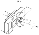
まず、本発明の第1の実施形態を説明する。図1は、本発明の第1の実施形態が適用された光学部品3,4をホルダ2に事前にモジュール単位に組立をしたサブアセンブリ2を、前記光学部品を使用する装置の筺体1の該当部分へ組付け・接着固定した状態を示す斜視図である。図2は、図1の光学部品を保持したサブアセンブリ2を、前記光学部品を使用する装置の筺体1へ組付ける概略の組立手順を示す斜視図である。図3(a),(b),(c)は、図2の組立手順毎の断面図である。
First, a first embodiment of the present invention will be described. FIG. 1 shows a
図1に示すように、本実施形態の光学部品の固定構造は、主に、筐体1と、LD3とレンズ4が固定されたホルダ(サブアセンブリ)2と、それらをホルダ側光軸6の位置を調整して接着固定するUV硬化型接着剤5a、5bから構成される。ここで、筐体1は、光ディスクの記録、再生に用いられる光ピックアップ装置やレーザディスプレイに用いられるRGB3原色光源モジュール装置のレーザダイオードや受光素子等を接着固定する筐体の一部分を図示したもので、上記装置全体の構成を図7、図8に示す。
As shown in FIG. 1, the optical component fixing structure of the present embodiment mainly includes a
図7は、本発明の第1の実施形態が適用された光ピックアップ装置701の構成部品と組立方法を説明する展開斜視図である。本実施形態の光ピックアップ装置701は、光ピックアップケース(筐体)702と、第1のLDモジュール703(図1の光学部品3,4を保持したサブアセンブリ2に該当)と、第2のLDモジュール704(図1の光学部品3,4を保持したサブアセンブリ2に該当)と、プリズム705と、反射ミラー706と、アクチュエータ707と、対物レンズ708と、レンズ709と、受光素子モジュール710と、を有する。
FIG. 7 is an exploded perspective view for explaining components and an assembling method of the
上記構成の光ピックアップ装置701において、第1のLDモジュール703、第2のLDモジュール704からの出射光は、プリズム705で合成または反射され、反射ミラー706を介して、アクチュエータ707上に配置された対物レンズ708に導き、光ディスク711上でスポットを収束させる。光ディスク711からの反射光は、対物レンズ708及び反射ミラー706、プリズム705、レンズ709を介して受光素子710に結像される。
In the
以上の光学系を実現するために、光ピックアップケース702に対し、アクチュエータ707、反射ミラー706、プリズム705、レンズ709等の内部部品は組立方向714で実装され、その後、第1のLDモジュール703は組立方向715で、第2のLDモジュール704は組立方向716で、受光素子モジュール710は組立方向717で位置調整後、接着固定される。また、光ピックアップ装置701自身は、主軸712と副軸713により、回転している光ディスクの半径方向に移動し、光信号の読み書き可能な構成としている。
In order to realize the above optical system, internal components such as the
図8は、本発明の第1の実施形態が適用されたRGB3原色光源モジュール装置801の構成部品と組立方法を説明する斜視図である。本実施形態のRGB3原色光源モジュール装置801は、RGBモジュールケース(筐体)802と、緑色のLDモジュール803(図1の光学部品3,4を保持したサブアセンブリ2に該当)と、赤色のLDモジュール804(図1の光学部品3,4を保持したサブアセンブリ2に該当)と、青色のLDモジュール805(図1の光学部品3,4を保持したサブアセンブリ2に該当)と、第1の合成ミラー806と、第2の合成ミラー807と、2方向首振りミラー808と、を有する。
FIG. 8 is a perspective view for explaining components and an assembling method of the RGB three primary color light
上記構成のRGB3原色光源モジュール装置801において、LDモジュール803からの緑色出射光813、LDモジュール804からの赤色出射光814は、第1の合成ミラー806で合成され、その合成光とLDモジュール805からの青色出射光815とが第2の合成ミラー807で合成されたビームとなり、2方向首振りミラー808で、スクリーン809上に、3色RGB合成ビーム816を2次元走査して、画像を投射する。
以上の光学系を実現するために、RGBモジュールケース802に対し、緑色のLDモジュール803と、赤色のLDモジュール804と、青色のLDモジュール805と、第1の合成ミラー806と、第2の合成ミラー807と、2方向首振りミラー808が、位置調整後、接着固定される。
In the RGB three primary color light
In order to realize the above optical system, a
これらの装置に使用される、図1の光学部品の固定構造は、図2に示すように、LD3とレンズ4が、ホルダ2に、ホルダ側光軸6の方向(Z軸−方向)にレーザ光が出射するようにサブ組立されている。次に、ホルダ連結部23が、筐体1の筐体中心U溝12に対して挿入されるように、ホルダY軸移動101でY軸−方向に降下される。更に、筐体基準面13に対し、ホルダ基準面25が接触するように、ホルダZ軸移動102でZ軸−方向に水平移動する。そして、ホルダ孔21a、21bから、接着剤塗布装置のニードル(図示無し)を挿入し、筐体貫通孔11a、11bを通して、UV硬化型接着剤5a、5bを塗布する。最後に、UV光源201a、201bを用いて、筐体貫通孔中心8a、8bに沿ってUV光を照射し、UV硬化型接着剤5a、5bを硬化固定する。
As shown in FIG. 2, the
更に、図3を用いて光軸の調整方法と光学部品の固定構造を詳細に説明する。図3は、図1の光学部品の固定構造の斜視図において、ホルダ側光軸6を面内に含むA-A’切断面で切断して示した光学部品の固定構造を組立てる手順毎の断面図である。 Further, the optical axis adjustment method and the optical component fixing structure will be described in detail with reference to FIG. FIG. 3 is a perspective view of the optical component fixing structure shown in FIG. 1, and shows a cross section for each procedure for assembling the optical component fixing structure shown by cutting along the AA ′ cut surface including the holder-side optical axis 6 in the plane. FIG.
まず、図3(a)で、レンズ付LDのサブアセンブリ2を説明する。ホルダ2は、ホルダ前プレート22とホルダ後プレート24とを円筒状のホルダ連結部23で連結した構造をしており、ホルダ連結部23には、LD3の発光部を挿入して、発光されたレーザビームを通すためのホルダ中心孔27が開けられている。
ホルダ2のホルダ中心孔27にLD3の発光部を挿入し、同時にレンズ4をホルダ前プレート22の前面に位置決めステージ等(図示無し)を用いて位置決め・調整可能とする。LD3の電極に電気接続(図示無し)して発光状態となったLD3をZ調芯104でZ軸+−方向に前後に調整して、レンズ4から出射されるビームが、平行ビーム、又は所望の焦点距離となるように決定して、LD3にUV硬化型接着剤31を塗布し、UV照射(図示無し)して硬化固定する。その後、レンズ4をXY調芯103でX軸Y軸の+−方向に調芯・位置決めして、レンズ4から出射されるビームがホルダ基準面25に対して垂直となるホルダ側光軸6と一致するようにビーム角度を調整する。そして、レンズ4にUV硬化型接着剤41を塗布し、UV照射(図示無し)して硬化固定し、LD3とレンズ4が接着されたホルダ2のサブアセンブリが完了する。ちなみに、ここでは、ホルダ2にLDとレンズが接着された構成を明示したが、ホルダに受光素子とレンズを接着させた構成でも同様に適用できる。
First, the
The light emitting portion of the
次に、図3(b)で、レンズ付LDのサブアセンブリ2の筐体1への組立を説明する。図3(b)は、図2でホルダ連結部23が筐体1の筐体中心U溝12に対して、ホルダY軸移動101で垂直に降下挿入された状態の断面図である。まず、ホルダ孔21a、21bが、筐体貫通孔11a、11bにそれぞれ対向するように配置する。次に、ホルダ前プレート22のホルダ前プレート面26と筐体1の筐体外面15が接触しないように、また、筐体1の筐体基準面13と、ホルダ後プレート24のホルダ基準面25が接触しないようにして、筐体1の筐体側光軸7に対し、組立られたホルダ2のサブアセンブリをXY調芯105でX軸Y軸の+−方向に調芯・位置決めして、レンズ4から出射されるビーム位置を調整する。ここで、筐体側光軸7とは、筐体上で光学部品を搭載すべき理想的な光軸のことである。これは、筐体だけを見ても筐体側光軸7は決められず、実際にLDを光らせて筐体上に仮位置決めして、その他の光学部品も筐体上に仮位置決めして、光の入出力関係が成り立つように位置決めを調整して決定された光軸のことである。
Next, referring to FIG. 3B, the assembly of the lens-attached
最後に、図3(b),(c)で、接着剤の塗布、硬化を説明する。まず、筐体基準面13に対し、ホルダ基準面25が接触するように、ホルダZ軸移動102でZ軸−方向に移動する。筐体の筐体貫通孔11a、11bが開けられている面(筐体内面14)は、筐体基準面13より段差を設けてZ軸−方向に掘り下げて形成されていて、筐体基準面13へホルダ基準面25を接触させた際に、筐体貫通孔11a、11bとホルダ孔21a、21bとの間には、図4(a)に示すように厚さがt2の隙間が形成されるようになっている。
Finally, application and curing of the adhesive will be described with reference to FIGS. First, the holder Z-
そして、ホルダ後プレート24に設けられたホルダ孔21a、21bから、筐体1に設けられた筐体貫通孔11a、11bを通して、ホルダ前プレート22のホルダ前プレート面26付近まで、接着剤塗布装置のニードル(図示無し)の先端をZ軸−方向に挿入する。そして、ニードルをZ軸+方向に引抜きながら、UV硬化型接着剤5a、5bを塗布し、ホルダ後プレート24に設けられたホルダ孔21a、21bの半分程度まで塗布した時点で、塗布を完了する。
Then, from the holder holes 21 a and 21 b provided in the
接着剤塗布装置のニードル先端から塗布されたUV硬化型接着剤5a、5bは、最初にホルダ前プレート22のホルダ前プレート面26に当ることになる。また、ホルダ前プレート面26と筐体1の筐体外面との間には隙間を形成している。しかし、UV硬化型接着剤は粘性があり、液体状というよりゲル状に近いため、ニードルをZ軸+方向に引抜きながらUV硬化型接着剤5a、5bを塗布する速度を適切に調整することにより、前記隙間へ漏れ出る接着剤の量はほとんど無く、前記ホルダ前プレート面26に接着した円柱状のUV硬化型接着剤5a、5bが形成される。
最後に、UV光源201a、201bを用いて、筐体貫通孔中心8a、8bに沿ってUV光を照射し、UV硬化型接着剤5a、5bを硬化固定する。
The UV
Finally, UV light is irradiated along the through-
ここで、UV硬化時、筐体1とホルダ2の関係を説明する。一般にUV硬化型接着剤は液体から固体へUV硬化する際に、%オーダで体積が収縮する。ホルダ後プレート24に設けられたホルダ孔21a、21b内に充填されたUV硬化型接着剤5a、5bは、UV光源201a、201bに近い、開放端Cから先にUV硬化を始め、筐体貫通孔中心8a、8bに沿って、筐体貫通孔11a、11b内がUV硬化し、ホルダ前プレート22のホルダ前プレート面26上の固定端B側が最後にUV硬化する。このため、開放端C側からUV硬化収縮により、UV硬化収縮力51が発生し、筐体1はホルダ後プレート24側へ筐体押付力52が作用し、筐体基準面13とホルダ基準面25が接触面Dで密着する。以上より、組立時に、UV硬化型接着剤5a、5bのUV硬化収縮を利用して、筐体1とホルダ2を密着して組み立てることができ、組立初期には、サブミクロンオーダの位置ずれを防止できる効果がある。
Here, the relationship between the
次に、本実施形態の光学部品の固定構造が、温度サイクルのある使用環境においてもサブミクロンオーダの位置ずれを防止できる効果があると想定される理由を、信頼性試験時を想定して、筐体1とホルダ2の関係を図4を用いて説明する。一般に接着剤は熱膨張係数が金属やガラス等の部品に比べて大きく、これにより部品の位置ずれが発生しやすいため、接着剤自身の熱膨張収縮が繰り返し発生する、温度サイクル試験での状況を想定する。
Next, the reason why it is assumed that the fixing structure of the optical component of the present embodiment has an effect of preventing the positional shift of the submicron order even in the use environment with the temperature cycle is assumed at the time of the reliability test. The relationship between the
まず、図4(a)は、例えば70℃から90℃程度の高温の状態を示す。高温時には、UV硬化型接着剤5a、5b全体が体積膨張するが、Z軸−方向には、ホルダ前プレート面26上の固定端Bで拘束され、更に筐体貫通孔11a、11b及びホルダ孔21a、21bでも拘束されるため、Z軸+方向に膨張する。更に一般に接着剤は高温で軟化し、弾性率(ヤング率)は低下するため、固定端B側から膨張し、開放端C側の軟化した接着剤表面もZ軸+方向へ変形する。このため、固定端B側から開放端C側に向けて、接着剤自身は体積膨張し膨張力53を発生し、Z軸+方向に筐体押付力54が発生する。この結果、図3(c)の組立時から引き続いて、筐体1はホルダ後プレート24側へ筐体押付力52が作用し、筐体基準面13とホルダ基準面25が接触面Dで密着する。ここで、筐体1の筐体貫通孔11a、11bを挟んで、Z軸−方向でホルダ前プレート面26上の固定端Bと筐体外面15で挟まれる接着剤長さをt1とし、Z軸+方向で筐体内面14とホルダ後プレート24のホルダ基準面25とで挟まれる接着剤長さをt2とする。例えば、t1=0.8mm、t2=0.5mmを想定する。
(数1) t2<t1
が成立する場合、Z軸+方向に確実に密着させることができるので、この関係の配置とすることがより望ましい。
First, FIG. 4A shows a high temperature state of, for example, about 70 ° C. to 90 ° C. When the temperature is high, the entire UV
(Equation 1) t2 <t1
Is established, this arrangement is more desirable because it is possible to ensure close contact in the + Z-axis direction.
一方、図4(b)は、例えば−40℃から−20℃程度の低温の状態を示す。低温時には、UV硬化型接着剤5a、5b全体が体積収縮する。ここで、筐体1の筐体貫通孔11a、11bを挟んで、Z軸−方向でホルダ前プレート面26上の固定端Bと筐体外面15で挟まれる接着剤長さをt1とし、Z軸+方向で筐体内面14とホルダ後プレート24のホルダ孔21a、21b内の開放端Cとで挟まれる接着剤長さをt2+t3とする。
(数2) t1<t2+t3
が成立する場合、t1で発生するB側収縮力55より、t2+t3で発生するC側収縮力56が大きくなり、Z軸+方向に筐体押付力57が発生する。この結果、図3(c)の組立時から引き続いて、筐体1はホルダ後プレート24側へ筐体押付力52が作用し、筐体基準面13とホルダ基準面25が接触面Dで密着する。
On the other hand, FIG. 4B shows a low temperature state of, for example, about −40 ° C. to −20 ° C. At low temperatures, the entire UV
(Expression 2) t1 <t2 + t3
Is established, the C-
以上より、高温及び低温時に、UV硬化型接着剤5a、5bの熱膨張収縮を利用して、筐体1とホルダ2の密着を維持することができ、前述の組立初期に加えて、温度サイクル試験でも、サブミクロンオーダの位置ずれを防止できる効果がある。また、60℃90%等の高温高湿試験では、一般に接着剤は吸湿して膨潤するので、上記高温時の挙動と同等の効果が期待できる。
As described above, the thermal expansion / contraction of the UV
次に、本発明の第2の実施形態を図5を用いて説明する。図5は実施例1の図2同様に、光学部品の固定構造の概略の組立手順を示す斜視図である。まず、図2同様に、LD3とレンズ4付のホルダ2のサブアセンブリが先に組立られている。次に、ホルダ連結部23が、筐体71の筐体中心U溝12に対して挿入されるように、ホルダY軸移動101でY軸−方向に降下される。更に、筐体基準面13に対し、ホルダ基準面25が接触するように、ホルダZ軸移動102でZ軸−方向に水平移動する。ここで、筐体71には、筐体貫通U溝61a、61bが設けてあるため、Y軸+方向から、接着剤塗布装置のニードル(図示無し)をホルダ前プレート22のホルダ前プレート面26に近づけ塗布を始める。筐体貫通U溝61a、61bを経由し、ホルダ後プレート24に設けられたホルダ孔21a、21bの中へZ軸+方向に半分程度まで塗布した時点で、塗布を完了する。最後に、UV光源201a、201bを用いて、筐体貫通U溝中心72a、72bに沿ってUV光を照射し、UV硬化型接着剤を硬化固定する。
Next, a second embodiment of the present invention will be described with reference to FIG. FIG. 5 is a perspective view showing a schematic assembling procedure of the fixing structure of the optical component, similarly to FIG. 2 of the first embodiment. First, as in FIG. 2, the subassembly of the
本実施例では、筐体71に筐体貫通U溝61a、61bを設けたので、図2のように、接着剤塗布装置のニードルをホルダ孔21a、21bからホルダ前プレート面26付近まで挿入する必要がなくなり、ニードルを筐体貫通U溝61a、61bの上部の空間へ挿入して、筐体貫通U溝内に接着剤を塗布することで柱状の接着剤を形成することに代えられるので、UV硬化型接着剤の塗布が簡単になる効果がある。
In this embodiment, since the housing through U-grooves 61a and 61b are provided in the
次に、本発明の第3の実施形態を図6(a)の展開斜視図、図6(b)の断面図を用いて説明する。本実施形態の筐体301と、ホルダ302の接合部の関係は、第1の実施形態の図2の展開斜視図、図3(c)の断面図と比較すると明らかなように、ホルダ前プレート22とホルダ後プレート24に相当する筐体301の筐体前プレート322と筐体後プレート324を構成し、筐体1の筐体貫通孔11a、11bが形成された接合部14に相当するホルダ302の接合プレート312を構成している。筺体側の接合部とホルダ側の接合部とを、柱状に塗布して硬化させた接着剤によって接着固定する原理は、実施形態1と同じである。
Next, a third embodiment of the present invention will be described with reference to a developed perspective view of FIG. 6A and a sectional view of FIG. The relationship between the
まず、図2同様に、LD3とレンズ4付のホルダ302のサブアセンブリ2が先に組立られている。本実施形態のホルダ302は、LD3とレンズ4の光軸を調芯して接着固定するための円筒形のホルダ本体302と、筐体301との接合部を構成するフランジ状の接合プレート312が形成されている。接合プレート312には、ホルダ貫通孔311a、311bが開けられている。
First, as in FIG. 2, the
前記ホルダ302のサブアセンブリ2を、筐体前プレート322と筐体後プレート324に形成された筐体中心U溝323に挿入(ホルダY軸移動106)して、ホルダ貫通孔311a、311bが、筐体後プレート324に形成された筐体孔321a、321bにそれぞれ対向するように配置する。続いて、筐体301の筐体側光軸7に対し、組立られたホルダ302のサブアセンブリ2をXY調芯して位置決めして、レンズ4から出射されるビーム位置を調整する。
The
次に、筐体基準面325に対し、ホルダ基準面313が接触するように、ホルダ302のサブアセンブリ2をZ軸+方向に移動107する。そして、筐体後プレート324に設けられた筐体孔321a、321bから、ホルダ302の接合プレート312に設けられたホルダ貫通孔311a、311bを通して、筐体前プレート322の筐体前プレート面326付近まで、接着剤塗布装置のニードル(図示無し)の先端をZ軸−方向に挿入する。そして、ニードルをZ軸+方向に引抜きながら、UV硬化型接着剤5a、5bを塗布し、筐体後プレート324に設けられた筐体孔321a、321b内の奥行き方向の半分程度まで塗布した時点で、塗布を完了する。最後に、UV光源201a、201bを用いて、筐体貫通孔中心308a、308bに沿ってUV光を照射し、UV硬化型接着剤5a、5bを硬化固定する。
Next, the
UV硬化型接着剤5a、5bを塗布するために、接着剤塗布装置のニードルを挿入する開放端C側の孔を、前述の図1から図5ではホルダ側に設けたが、同様に図6(b)では筐体側に筐体孔321a、321bを設けて開放端Cを構成することができる。従って、図6(b)の構成でも、図3(c)と同様に、組立時に、UV硬化型接着剤5a、5bのUV硬化収縮を利用して、筐体301とホルダ302を密着して組み立てることができる。また、図4(a),(b)と同様に、高温及び低温時に、UV硬化型接着剤5a、5bの熱膨張収縮を利用して、筐体301とホルダ302の密着を維持することができ、実施形態1の構成と同様に、組立初期と温度サイクル試験でも、サブミクロンオーダの位置ずれを防止できる効果がある。また、組立時及び信頼性試験(温度サイクル)を通して常に筐体と部品が特定の面で接触するようにしているため、位置ずれ防止に加え、放熱性も向上した光学部品の固定構造を提供できる。更に、筐体と部品以外には接着剤だけを用いているので、バネ等による押付部品が不要となり、部品点数を減らし、材料費、組立費用等を低減する効果もある。
In order to apply the UV
以上、説明した本発明の実施形態1〜3において、光学部品はLD(レーザダイオード)の例で説明したが、同様の構成にて、受光素子等の他の光学部品にも適用が可能である。
また、筐体、ホルダの材質としては、Zn,Mg,Alなどの金属のダイキャスト品が主に考えられるが、受光素子のように放熱性をそれ程必要としない場合には、樹脂製とすることも考えられる。
As described above, in the first to third embodiments of the present invention described above, the optical component has been described as an example of an LD (laser diode). However, the same configuration can be applied to other optical components such as a light receiving element. .
In addition, as the material of the housing and holder, metal die-cast products such as Zn, Mg, Al, etc. are mainly conceivable, but if the heat dissipation is not so required as in the light receiving element, it is made of resin. It is also possible.
また、UV硬化型接着剤は、アクリル系接着剤でも、エポキシ系接着剤でも同様に効果を得ることができる。 Also, the UV curable adhesive can obtain the same effect with an acrylic adhesive or an epoxy adhesive.
1 筐体
2 ホルダのサブアセンブリ
3 LD
4 レンズ
5a、5b UV硬化型接着剤
6 ホルダ側光軸
7 筐体側光軸
8a、8b 筐体貫通孔中心
11a、11b 筐体貫通孔
12 筐体中心U溝
13 筐体基準面
14 筐体内面
15 筐体外面
21a、21b ホルダ孔
22 ホルダ前プレート
23 ホルダ連結部
24 ホルダ後プレート
25 ホルダ基準面
26 ホルダ前プレート面
27 ホルダ中心孔
31、41 UV硬化型接着剤
51 UV硬化収縮力
52、54、57 筐体押付力
53 膨張力
55 B側収縮力
56 C側収縮力
61a、61b 筐体貫通U溝
71 筐体
72a、72b 筐体貫通U溝中心
101,106 ホルダY軸移動
102、107 ホルダZ軸移動
103 XY調芯
104 Z調芯
105 XY調芯
201a、201b UV光源
301 筐体
302 ホルダ
308a、308b 筐体貫通孔中心
311a、311b ホルダ貫通孔
312 ホルダ接合プレート
313 ホルダ基準面
321a、321b 筐体孔
322 筐体前プレート
323 筐体中心U溝
324 筐体後プレート
325 筐体基準面
326 筐体前プレート面
701 光ピックアップ装置
702 光ピックアップケース
703、704 LDモジュール
705 プリズム
706 反射ミラー
707 アクチュエータ
708 対物レンズ
709 レンズ
710 受光素子モジュール
711 光ディスク
712 主軸
713 副軸
714、715、716、717 組立方向
801 RGB3原色光源モジュール装置
802 RGBモジュールケース
803 緑色のLDモジュール
804 赤色のLDモジュール
805 青色のLDモジュール
806、807 合成ミラー
808 2方向首振りミラー
809 スクリーン
813 緑色出射光
814 赤色出射光
815 青色出射光
816 3色RGB合成ビーム
1
4 Lens 5a, 5b UV curable adhesive 6 Holder side optical axis 7 Case side optical axis 8a, 8b Case through hole center 11a, 11b Case through hole 12 Case center U groove 13 Case reference surface 14 Case inner surface 15 Housing outer surface 21a, 21b Holder hole 22 Holder front plate 23 Holder connecting portion 24 Holder rear plate 25 Holder reference surface 26 Holder front plate surface 27 Holder center hole 31, 41 UV curable adhesive 51 UV curable shrinkage force 52, 54 , 57 Case pressing force 53 Expansion force 55 B side contraction force 56 C side contraction force 61a, 61b Case penetration U groove 71 Case 72a, 72b Case penetration U groove center 101, 106 Holder Y-axis movement 102, 107 Holder Z axis movement 103 XY alignment 104 Z alignment 105 XY alignment 201a, 201b UV light source 301 Case 302 Holder 308a, 308b Case through hole center 311a, 311b Holder Through hole 312 Holder joining plate 313 Holder reference surface 321a, 321b Housing hole 322 Housing front plate 323 Housing center U groove 324 Housing rear plate 325 Housing reference surface 326 Housing front plate surface 701 Optical pickup device 702 Optical pickup Cases 703, 704 LD module 705 Prism 706 Reflection mirror 707 Actuator lens 708 Objective lens 709 Lens 710 Light receiving element module 711 Optical disc 712 Main shaft 713 Secondary shaft 714, 715, 716, 717 Assembly direction 801 RGB three primary color light source module device 802 RGB module case 803 green LD module 804 Red LD module 805 Blue LD modules 806 and 807 Composite mirror 808 Two-way swing mirror 809 Screen 813 Green light 814 Red outgoing light 815 Blue outgoing light 816 3-color RGB combined beam
Claims (13)
前記光学部品が実装される装置筺体と、
その光軸がホルダ基準面に対して所定の角度に接着固定された光学部品を保持するホルダと、
前記ホルダには、前記装置筐体と接合するための第1のプレート部と、第2のプレート部と、および前記第1のプレート部、第2のプレート部とを連結する連結部とが形成され、
前記第2のプレート部には複数の接合孔が形成され、
前記装置筐体の接合部には、前記ホルダの連結部を嵌合させるU溝と、該U溝の周囲に複数の貫通孔が形成され、
前記ホルダの連結部が前記装置筐体の接合部の前記U溝に嵌合されて、前記第2のプレート部の各接合孔と、および前記装置筐体の各貫通孔とをそれぞれ連続して接続して、前記ホルダの第1のプレート部に接着した複数の硬化された円柱状の接着剤と、
を有することを特徴とする光学部品の固定構造。 An optical component fixing structure for fixing an optical component to an apparatus housing,
An apparatus housing on which the optical component is mounted;
A holder for holding an optical component whose optical axis is bonded and fixed at a predetermined angle with respect to a holder reference plane;
The holder is formed with a first plate portion for joining to the apparatus housing, a second plate portion, and a connecting portion for connecting the first plate portion and the second plate portion. And
A plurality of joining holes are formed in the second plate portion,
The joint portion of the apparatus housing is formed with a U groove for fitting the connecting portion of the holder, and a plurality of through holes around the U groove,
The connecting portion of the holder is fitted into the U-groove of the joint portion of the device casing, and the joint holes of the second plate portion and the through holes of the device housing are respectively continuous. connected, and a plurality of cured cylindrical adhesive adhered to the first plate portion of the holder,
An optical component fixing structure characterized by comprising:
前記光学部品が実装される装置筺体と、
その光軸がホルダ基準面に対して所定の角度に接着固定された光学部品を保持するホルダと、
前記ホルダには、前記装置筐体と接合するための第1のプレート部と、第2のプレート部と、および前記第1のプレート部、第2のプレート部とを連結する連結部とが形成され、
前記第2のプレート部には複数の接合孔が形成され、
前記装置筐体の接合部には、前記ホルダの連結部を嵌合させる中心U溝と、該中心U溝の周囲に複数の貫通U溝が形成され、
前記ホルダの連結部が前記装置筐体の接合部の前記中心U溝に嵌合されて、前記第2のプレート部の各接合孔と、および前記装置筐体の各貫通U溝とをそれぞれ連続して接続して、前記ホルダの第1のプレート部に接着した複数の硬化された柱状の接着剤と、
を有することを特徴とする光学部品の固定構造。 An optical component fixing structure for fixing an optical component to an apparatus housing,
An apparatus housing on which the optical component is mounted;
A holder for holding an optical component whose optical axis is bonded and fixed at a predetermined angle with respect to a holder reference plane;
The holder is formed with a first plate portion for joining to the apparatus housing, a second plate portion, and a connecting portion for connecting the first plate portion and the second plate portion. And
A plurality of joining holes are formed in the second plate portion,
Wherein the junction of the device housing, a central U-groove fitting the connecting portion of the holder, a plurality of through-U groove around the central U-groove is formed,
The connecting portion of the holder is fitted into the center U groove of the joint portion of the apparatus housing, and the joint holes of the second plate portion and the through U grooves of the device housing are respectively continuous. connected through a plurality of cured columnar adhesive adhered to the first plate portion of the holder,
An optical component fixing structure characterized by comprising:
前記光学部品が実装される装置筺体と、
その光軸がホルダ基準面に対して所定の角度に接着固定された光学部品を保持するホルダと、
前記ホルダには、前記光学部品が接着固定されたホルダ本体部に接合プレート部が形成され、
前記接合プレート部には複数のホルダ貫通孔が形成され、
前記装置筐体の接合部には、前記ホルダの接合プレート部を挟み込んで接合するための第1のプレート部と、第2のプレート部とが形成され、該第1のプレート部、および該第2のプレート部には前記ホルダ本体部を嵌合させるU溝が形成され、
前記第2のプレート部には複数の接合孔が形成され、
前記ホルダ本体部が前記装置筐体の接合部の前記U溝に嵌合されて、前記第1のプレート部、および前記第2のプレート部の間に挿入された前記接合プレート部の各ホルダ貫通孔と、および前記装置筐体の前記第2のプレート部の各接合孔とをそれぞれ連続して接続して、前記第1のプレート部に接着した複数の硬化された円柱状の接着剤と、
を有することを特徴とする光学部品の固定構造。 An optical component fixing structure for fixing an optical component to an apparatus housing,
An apparatus housing on which the optical component is mounted;
A holder for holding an optical component whose optical axis is bonded and fixed at a predetermined angle with respect to a holder reference plane;
In the holder, a bonding plate portion is formed on a holder main body portion to which the optical component is bonded and fixed,
A plurality of holder through holes are formed in the joining plate portion,
The joining portion of the apparatus housing is formed with a first plate portion and a second plate portion for sandwiching and joining the joining plate portion of the holder, and the first plate portion and the first plate portion A U-groove for fitting the holder main body portion is formed in the plate portion of 2,
A plurality of joining holes are formed in the second plate portion,
The holder main body portion is fitted in the U groove of the joint portion of the apparatus housing, and the holder plate passes through the joint plate portion inserted between the first plate portion and the second plate portion. and the hole, and the device of the second plate portion of the housing and the joining hole each connected sequentially, a plurality of cured cylindrical adhesive adhered to the first plate portion When,
An optical component fixing structure characterized by comprising:
(数1) t2<t1
の条件が成立するように構成されていることを特徴とする請求項1に記載の光学部品の固定構造。 The second plate portion of the adhesive length t1, and the through hole inlet of the device housing the holder between the through hole inlet of the device housing and the adhesive portion of the first plate portion of the holder If the length of the adhesive between the joint hole entrance and t2 is t2,
(Equation 1) t2 <t1
The structure for fixing an optical component according to claim 1, wherein the condition is satisfied.
(数2) t1<t2+t3
の条件が成立するように構成されていることを特徴とする請求項4に記載の光学部品の固定構造。 To the adhesive that is cured in the joining hole of the second plate portion of the holder, from the junction hole entrance, the adhesive length of the distance to the open end of the adhesive in the joint hole When t3, (Expression 2) t1 <t2 + t3
The optical component fixing structure according to claim 4, wherein the following condition is satisfied.
(数1) t2<t1
の条件が成立するように構成されていることを特徴とする請求項2に記載の光学部品の固定構造。 The adhesive lengths between the through U groove entrance of the device housing and the adhesive portion of the first plate portion of the holder t1, and the device housing through U groove inlet and the second of said holder When the adhesive lengths between the joining hole entrance of the plate portion and t2,
(Equation 1) t2 <t1
The structure for fixing an optical component according to claim 2, wherein the condition is satisfied.
(数2) t1<t2+t3
の条件が成立するように構成されていることを特徴とする請求項6に記載の光学部品の固定構造。 To the adhesive that is cured in the joining hole of the second plate portion of the holder, from the junction hole entrance, the adhesive length of the distance to the open end of the adhesive in the joint hole When t3, (Expression 2) t1 <t2 + t3
The optical component fixing structure according to claim 6, wherein the following condition is satisfied.
前記装置筐体と接合するための第1のプレート部と、第2のプレート部と、および前記第1、第2のプレート部とを連結する連結部とが形成され、前記第2のプレート部には複数の接合孔が形成されたホルダに対して、前記光学部品の光軸をホルダ基準面に対して所定の角度になるように調芯して、該光学部品を樹脂により接着固定する工程と、
前記装置筐体の接合部に形成されたU溝へ前記ホルダの連結部を挿入して、前記第2のプレート部の各接合孔と、前記装置筐体の前記U溝の周囲に形成された複数の貫通孔とを対向させて位置決めする工程と、
前記ホルダの第1のプレート部に接着して、前記貫通孔内部、および前記接合孔内部に掛けて連続してUV硬化型接着剤を塗布する工程と、
前記接合孔の外部から、前記貫通孔の中心に沿ってUV光を照射して前記UV硬化型接着剤を硬化させる工程と、
を有することを特徴とする光学部品の固定方法。 An optical component fixing method for fixing an optical component to an apparatus housing,
A first plate part for joining to the apparatus housing, a second plate part, and a connecting part for connecting the first and second plate parts are formed, and the second plate part Aligning the optical axis of the optical component with a holder at a predetermined angle with respect to the holder in which a plurality of bonding holes are formed, and bonding and fixing the optical component with a resin When,
The connecting portion of the holder is inserted into the U groove formed in the joint portion of the apparatus housing, and is formed around each joint hole of the second plate portion and the U groove of the device housing. Positioning a plurality of through holes to face each other;
Adhering to the first plate portion of the holder, applying the UV curable adhesive continuously over the inside of the through hole and the inside of the joint hole;
Irradiating UV light along the center of the through hole from the outside of the bonding hole to cure the UV curable adhesive;
A method of fixing an optical component, comprising:
前記装置筐体の接合部に形成された中央U溝へ前記ホルダの連結部を挿入して、前記第2のプレート部の各接合孔と、前記装置筐体の前記中央U溝の周囲に形成された複数の貫通U溝とを対向させて位置決めする工程と、
前記ホルダの第1のプレート部に接着して、前記貫通U溝内部、および前記接合孔内部に掛けて連続してUV硬化型接着剤を塗布する工程と、
前記接合孔の外部から、前記貫通U溝の中心に沿ってUV光を照射して前記UV硬化型接着剤を硬化させる工程と、
を有することを特徴とする請求項10に記載の光学部品の固定方法。 Instead of a plurality of through holes formed around the U groove of the device housing, a plurality of through U grooves are formed,
The connecting portion of the holder is inserted into a central U-groove formed in the joint portion of the apparatus housing, and is formed around each joint hole of the second plate portion and the central U-groove of the device housing. Positioning the plurality of through U-grooves facing each other;
Adhering to the first plate portion of the holder, and applying a UV curable adhesive continuously over the inside of the through U groove and the inside of the joint hole;
Irradiating UV light from the outside of the joining hole along the center of the through-U groove to cure the UV curable adhesive;
The method of fixing an optical component according to claim 10, comprising:
前記第1、第2のLDモジュール、および受光素子モジュールの少なくとも1つのモジュールを、前記光ピックアップケースに接着固定する工程が、
前記モジュールは、前記光ピックアップケースと接合するための第1のプレート部と、第2のプレート部と、および前記第1、第2のプレート部とを連結する連結部とが形成され、前記第2のプレート部には複数の接合孔が形成されたホルダに対して、光学部品の光軸をホルダ基準面に対して所定の角度になるように調芯して、該光学部品を樹脂により接着固定した構成であり、
前記光ピックアップケースの接合部に形成されたU溝へ前記モジュールのホルダの連結部を挿入する工程と、
前記第2のプレート部の各接合孔と、前記光ピックアップケースの前記U溝の周囲に形成された複数の貫通孔とを対向させて位置決める工程と、
前記ホルダの第1のプレート部に接着して、前記貫通孔内部、および前記接合孔内部に掛けて連続してUV硬化型接着剤を塗布する工程と、
前記貫通孔の中心に沿ってUV光を照射して前記UV硬化型接着剤を硬化させる工程とを有することを特徴とする光ピックアップ装置の製造方法。 A method of manufacturing an optical pickup device comprising an optical pickup case including a first LD module, a second LD module, a prism, a reflecting mirror, an actuator, an objective lens, a lens, and a light receiving element module. There ,
The step of adhering and fixing at least one of the first and second LD modules and the light receiving element module to the optical pickup case,
The module includes a first plate portion for joining the optical pickup case, a second plate portion, and a connecting portion for connecting the first and second plate portions, The optical plate of the optical component is aligned to a predetermined angle with respect to the holder reference plane with respect to the holder in which a plurality of bonding holes are formed in the plate portion 2 and the optical component is bonded with resin. A fixed configuration,
Inserting a connection portion of the holder of the module to the U groove that is formed at the junction of the optical pickup casing,
Said second plate portion each joint hole of the steps Ru positioning said to face a plurality of through-holes formed around the U-groove of the optical pickup casing,
Adhering to the first plate portion of the holder, applying the UV curable adhesive continuously over the inside of the through hole and the inside of the joint hole;
Method of manufacturing an optical pickup device characterized by a step of irradiating with UV light Ru curing the UV curable adhesive along the center of the through hole.
前記RGB各色のLDモジュールの少なくとも1つのLDモジュールを、前記RGBモジュールケースに接着固定する工程が、
前記LDモジュールは、前記RGBモジュールケースと接合するための第1のプレート部と、第2のプレート部と、および前記第1、第2のプレート部とを連結する連結部とが形成され、前記第2のプレート部には複数の接合孔が形成されたホルダに対して、光学部品の光軸をホルダ基準面に対して所定の角度になるように調芯して、該光学部品を樹脂により接着固定した構成であり、
前記RGBモジュールケースの接合部に形成されたU溝へ前記モジュールのホルダの連結部を挿入する工程と、
前記第2のプレート部の各接合孔と、前記RGBモジュールケースの前記U溝の周囲に形成された複数の貫通孔とを対向させて位置決める工程と、
前記ホルダの第1のプレート部に接着して、前記貫通孔内部、および前記接合孔内部に掛けて連続してUV硬化型接着剤を塗布する工程と、
前記貫通孔の中心に沿ってUV光を照射して前記UV硬化型接着剤を硬化させる工程とを有することを特徴とするRGB3原色光源モジュール装置の製造方法。 A manufacturing method of an RGB three-primary-color light source module device including an RGB module case, an LD module for each RGB color, a first synthesis mirror, a second synthesis mirror, and a two-way swing mirror,
At least one LD module of the RGB colors LD modules, the step of bonding and fixing to the RGB module case,
The LD module includes a first plate portion for joining to the RGB module case, a second plate portion, and a connecting portion for connecting the first and second plate portions, The optical plate of the optical component is aligned at a predetermined angle with respect to the holder reference plane with respect to the holder having a plurality of bonding holes formed in the second plate portion, and the optical component is made of resin. Adhesive fixed configuration,
Inserting a connection part of the holder of the module into a U groove formed in a joint part of the RGB module case;
Said second plate portion each joint hole of the said Ru RGB module said positioning to face a plurality of through-holes formed around the U-shaped groove of the case process,
Adhering to the first plate portion of the holder, applying the UV curable adhesive continuously over the inside of the through hole and the inside of the joint hole;
Method for producing RGB3 primary light source module apparatus characterized by a step of irradiating with UV light along the center of the through hole Ru curing the UV-curable adhesive.
Priority Applications (4)
| Application Number | Priority Date | Filing Date | Title |
|---|---|---|---|
| JP2013025391A JP6031373B2 (en) | 2013-02-13 | 2013-02-13 | Optical component fixing structure, optical component fixing method, optical pickup device manufacturing method, and RGB three primary color light source module device manufacturing method |
| KR1020130136113A KR101574153B1 (en) | 2013-02-13 | 2013-11-11 | Fixed structure of optical component, method of fixing optical component, optical pickup device, and module device with rgb three primary color light source |
| CN201310571238.5A CN103984073B (en) | 2013-02-13 | 2013-11-13 | The fixed structure of optical component and method, optical take-up apparatus and RGB3 primary lights module |
| US14/086,048 US8902723B2 (en) | 2013-02-13 | 2013-11-21 | Fixing structure of optical component, fixing method of optical component, optical pick-up device, and module device with light sources of RGB three primary colors |
Applications Claiming Priority (1)
| Application Number | Priority Date | Filing Date | Title |
|---|---|---|---|
| JP2013025391A JP6031373B2 (en) | 2013-02-13 | 2013-02-13 | Optical component fixing structure, optical component fixing method, optical pickup device manufacturing method, and RGB three primary color light source module device manufacturing method |
Publications (2)
| Publication Number | Publication Date |
|---|---|
| JP2014154195A JP2014154195A (en) | 2014-08-25 |
| JP6031373B2 true JP6031373B2 (en) | 2016-11-24 |
Family
ID=51276113
Family Applications (1)
| Application Number | Title | Priority Date | Filing Date |
|---|---|---|---|
| JP2013025391A Expired - Fee Related JP6031373B2 (en) | 2013-02-13 | 2013-02-13 | Optical component fixing structure, optical component fixing method, optical pickup device manufacturing method, and RGB three primary color light source module device manufacturing method |
Country Status (4)
| Country | Link |
|---|---|
| US (1) | US8902723B2 (en) |
| JP (1) | JP6031373B2 (en) |
| KR (1) | KR101574153B1 (en) |
| CN (1) | CN103984073B (en) |
Families Citing this family (4)
| Publication number | Priority date | Publication date | Assignee | Title |
|---|---|---|---|---|
| US9872407B2 (en) * | 2014-07-29 | 2018-01-16 | Sharp Kabushiki Kaisha | Electronic device |
| CN105764299B (en) * | 2014-12-19 | 2018-09-25 | 鹏鼎控股(深圳)股份有限公司 | Radiator structure and preparation method thereof |
| KR102490868B1 (en) | 2015-11-09 | 2023-01-20 | 삼성에스디아이 주식회사 | Battery rack |
| CN108827889B (en) * | 2018-06-13 | 2021-02-05 | 江西中医药大学 | Glue material identification method based on optical characteristics |
Family Cites Families (18)
| Publication number | Priority date | Publication date | Assignee | Title |
|---|---|---|---|---|
| JP2964698B2 (en) * | 1991-04-26 | 1999-10-18 | ソニー株式会社 | Objective lens holder, method of manufacturing the same, and objective lens holding member block |
| JP3848480B2 (en) * | 1998-06-08 | 2006-11-22 | アルプス電気株式会社 | Flexible printed circuit board mounting structure and recording / reproducing apparatus using the same |
| JP2000251268A (en) * | 1999-03-03 | 2000-09-14 | Sharp Corp | Grating adjustment mechanism of optical pickup apparatus |
| JP3663141B2 (en) * | 2001-02-23 | 2005-06-22 | 三洋電機株式会社 | Optical head photo detector mounting device |
| JP3841217B2 (en) * | 2003-06-17 | 2006-11-01 | 船井電機株式会社 | Optical pickup |
| JP2005032314A (en) | 2003-07-09 | 2005-02-03 | Arima Device Kk | Method for fixing optical component |
| JP4180496B2 (en) * | 2003-11-28 | 2008-11-12 | シャープ株式会社 | Optical pickup device |
| JPWO2006118037A1 (en) * | 2005-04-28 | 2008-12-18 | 松下電器産業株式会社 | Optical pickup device, optical information device having the optical pickup device, and optical information recording / reproducing device having the optical information device |
| JP2007184037A (en) * | 2006-01-06 | 2007-07-19 | Funai Electric Co Ltd | Optical pickup apparatus |
| JP2007200503A (en) * | 2006-01-30 | 2007-08-09 | Nidec Sankyo Corp | Optical head device and its manufacturing method |
| JP4538416B2 (en) * | 2006-02-03 | 2010-09-08 | 株式会社日立メディアエレクトロニクス | Optical pickup device, manufacturing method thereof, and optical drive device |
| JP4124234B2 (en) * | 2006-03-03 | 2008-07-23 | 船井電機株式会社 | Optical pickup |
| JP2007242203A (en) * | 2006-03-13 | 2007-09-20 | Funai Electric Co Ltd | Optical pickup |
| JP2008299973A (en) * | 2007-05-31 | 2008-12-11 | Toshiba Corp | Optical pickup device, optical disk drive provided with the same, and manufacturing method thereof |
| JP4934645B2 (en) * | 2008-06-30 | 2012-05-16 | 株式会社日立メディアエレクトロニクス | Optical pickup device and manufacturing method thereof |
| JP4637225B2 (en) * | 2008-10-17 | 2011-02-23 | パナソニック株式会社 | Optical pickup |
| JP5338788B2 (en) * | 2010-11-10 | 2013-11-13 | 船井電機株式会社 | LASER HOLDER AND OPTICAL PICKUP HAVING THE SAME |
| JP2012247529A (en) * | 2011-05-26 | 2012-12-13 | Hitachi Media Electoronics Co Ltd | Light source device and optical axis adjustment method |
-
2013
- 2013-02-13 JP JP2013025391A patent/JP6031373B2/en not_active Expired - Fee Related
- 2013-11-11 KR KR1020130136113A patent/KR101574153B1/en active IP Right Grant
- 2013-11-13 CN CN201310571238.5A patent/CN103984073B/en not_active Expired - Fee Related
- 2013-11-21 US US14/086,048 patent/US8902723B2/en not_active Expired - Fee Related
Also Published As
| Publication number | Publication date |
|---|---|
| CN103984073A (en) | 2014-08-13 |
| KR20140102114A (en) | 2014-08-21 |
| US8902723B2 (en) | 2014-12-02 |
| CN103984073B (en) | 2016-04-06 |
| JP2014154195A (en) | 2014-08-25 |
| US20140226452A1 (en) | 2014-08-14 |
| KR101574153B1 (en) | 2015-12-03 |
Similar Documents
| Publication | Publication Date | Title |
|---|---|---|
| JP6031373B2 (en) | Optical component fixing structure, optical component fixing method, optical pickup device manufacturing method, and RGB three primary color light source module device manufacturing method | |
| JP5923164B2 (en) | Laser module and manufacturing method thereof | |
| WO2010047147A1 (en) | Semiconductor laser module and method for manufacturing the same | |
| EP3502761A1 (en) | Light source unit | |
| US7613080B2 (en) | Optical pickup device and manufacturing method thereof | |
| JP2002269791A (en) | Optical head device | |
| JP2016018594A (en) | Light source device and electrical apparatus | |
| JP2015143732A (en) | Optical component fixing structure | |
| JP2008015036A (en) | Optical subassembly, optical module, and manufacturing method of optical subassembly | |
| WO2013128728A1 (en) | Optical module and production method for same | |
| JP2015064919A (en) | Optical component fixing structure, optical component fixing method, optical pickup device, and three-primary light source module device | |
| JP4934645B2 (en) | Optical pickup device and manufacturing method thereof | |
| JP2020008813A (en) | Optical module | |
| JP4453597B2 (en) | Optical device and manufacturing method thereof | |
| JP5287243B2 (en) | Optical transmission module and manufacturing method thereof | |
| US10228522B2 (en) | Bonding method, method of producing optical module, and optical module | |
| JP2013235626A (en) | Optical pickup device and method for manufacturing the same | |
| CN218546995U (en) | Laser radar transmitter and laser radar | |
| US9594216B1 (en) | Fiber optical switches | |
| JP4544018B2 (en) | Actuator device | |
| JP2010146642A (en) | Optical pickup device and method for manufacturing same | |
| JPH11160640A (en) | Manufacture of scanning optical device | |
| JP2014229334A (en) | Optical pickup apparatus, and optical disk drive apparatus | |
| WO2009145023A1 (en) | Light source module manufacturing method, and light source module | |
| JP2010097666A (en) | Optical pickup |
Legal Events
| Date | Code | Title | Description |
|---|---|---|---|
| A711 | Notification of change in applicant |
Free format text: JAPANESE INTERMEDIATE CODE: A712 Effective date: 20141006 |
|
| A621 | Written request for application examination |
Free format text: JAPANESE INTERMEDIATE CODE: A621 Effective date: 20150430 |
|
| A977 | Report on retrieval |
Free format text: JAPANESE INTERMEDIATE CODE: A971007 Effective date: 20160311 |
|
| A131 | Notification of reasons for refusal |
Free format text: JAPANESE INTERMEDIATE CODE: A131 Effective date: 20160405 |
|
| A521 | Request for written amendment filed |
Free format text: JAPANESE INTERMEDIATE CODE: A523 Effective date: 20160511 |
|
| TRDD | Decision of grant or rejection written | ||
| A01 | Written decision to grant a patent or to grant a registration (utility model) |
Free format text: JAPANESE INTERMEDIATE CODE: A01 Effective date: 20161011 |
|
| A61 | First payment of annual fees (during grant procedure) |
Free format text: JAPANESE INTERMEDIATE CODE: A61 Effective date: 20161024 |
|
| R150 | Certificate of patent or registration of utility model |
Ref document number: 6031373 Country of ref document: JP Free format text: JAPANESE INTERMEDIATE CODE: R150 |
|
| LAPS | Cancellation because of no payment of annual fees |