JP6030882B2 - Radio communication system, radio base station apparatus, and retransmission control method - Google Patents
Radio communication system, radio base station apparatus, and retransmission control method Download PDFInfo
- Publication number
- JP6030882B2 JP6030882B2 JP2012170258A JP2012170258A JP6030882B2 JP 6030882 B2 JP6030882 B2 JP 6030882B2 JP 2012170258 A JP2012170258 A JP 2012170258A JP 2012170258 A JP2012170258 A JP 2012170258A JP 6030882 B2 JP6030882 B2 JP 6030882B2
- Authority
- JP
- Japan
- Prior art keywords
- base station
- radio base
- station apparatus
- transmission
- retransmission
- Prior art date
- Legal status (The legal status is an assumption and is not a legal conclusion. Google has not performed a legal analysis and makes no representation as to the accuracy of the status listed.)
- Expired - Fee Related
Links
- 238000000034 method Methods 0.000 title claims description 44
- 238000004891 communication Methods 0.000 title claims description 29
- 230000005540 biological transmission Effects 0.000 claims description 158
- 230000011664 signaling Effects 0.000 claims description 11
- 230000008054 signal transmission Effects 0.000 claims description 8
- 238000012545 processing Methods 0.000 description 49
- 238000013507 mapping Methods 0.000 description 16
- 239000013256 coordination polymer Substances 0.000 description 6
- 101000741965 Homo sapiens Inactive tyrosine-protein kinase PRAG1 Proteins 0.000 description 5
- 102100038659 Inactive tyrosine-protein kinase PRAG1 Human genes 0.000 description 5
- 238000010586 diagram Methods 0.000 description 5
- 238000003780 insertion Methods 0.000 description 5
- 230000037431 insertion Effects 0.000 description 5
- 125000004122 cyclic group Chemical group 0.000 description 3
- 238000001514 detection method Methods 0.000 description 3
- 238000007726 management method Methods 0.000 description 3
- 238000012937 correction Methods 0.000 description 2
- 238000005516 engineering process Methods 0.000 description 2
- 239000013307 optical fiber Substances 0.000 description 2
- 238000013468 resource allocation Methods 0.000 description 2
- 238000010187 selection method Methods 0.000 description 2
- 101100417906 Synechocystis sp. (strain PCC 6803 / Kazusa) rre1 gene Proteins 0.000 description 1
- 230000012447 hatching Effects 0.000 description 1
- 230000007774 longterm Effects 0.000 description 1
- 238000010295 mobile communication Methods 0.000 description 1
- 230000003287 optical effect Effects 0.000 description 1
Images


Classifications
-
- H—ELECTRICITY
- H04—ELECTRIC COMMUNICATION TECHNIQUE
- H04W—WIRELESS COMMUNICATION NETWORKS
- H04W72/00—Local resource management
- H04W72/20—Control channels or signalling for resource management
- H04W72/23—Control channels or signalling for resource management in the downlink direction of a wireless link, i.e. towards a terminal
-
- H—ELECTRICITY
- H04—ELECTRIC COMMUNICATION TECHNIQUE
- H04B—TRANSMISSION
- H04B7/00—Radio transmission systems, i.e. using radiation field
- H04B7/02—Diversity systems; Multi-antenna system, i.e. transmission or reception using multiple antennas
- H04B7/022—Site diversity; Macro-diversity
- H04B7/024—Co-operative use of antennas of several sites, e.g. in co-ordinated multipoint or co-operative multiple-input multiple-output [MIMO] systems
-
- H—ELECTRICITY
- H04—ELECTRIC COMMUNICATION TECHNIQUE
- H04L—TRANSMISSION OF DIGITAL INFORMATION, e.g. TELEGRAPHIC COMMUNICATION
- H04L1/00—Arrangements for detecting or preventing errors in the information received
- H04L1/12—Arrangements for detecting or preventing errors in the information received by using return channel
- H04L1/16—Arrangements for detecting or preventing errors in the information received by using return channel in which the return channel carries supervisory signals, e.g. repetition request signals
- H04L1/18—Automatic repetition systems, e.g. Van Duuren systems
- H04L1/1812—Hybrid protocols; Hybrid automatic repeat request [HARQ]
- H04L1/1816—Hybrid protocols; Hybrid automatic repeat request [HARQ] with retransmission of the same, encoded, message
-
- H—ELECTRICITY
- H04—ELECTRIC COMMUNICATION TECHNIQUE
- H04L—TRANSMISSION OF DIGITAL INFORMATION, e.g. TELEGRAPHIC COMMUNICATION
- H04L1/00—Arrangements for detecting or preventing errors in the information received
- H04L1/12—Arrangements for detecting or preventing errors in the information received by using return channel
- H04L1/16—Arrangements for detecting or preventing errors in the information received by using return channel in which the return channel carries supervisory signals, e.g. repetition request signals
- H04L1/18—Automatic repetition systems, e.g. Van Duuren systems
- H04L1/1867—Arrangements specially adapted for the transmitter end
- H04L1/1887—Scheduling and prioritising arrangements
-
- H—ELECTRICITY
- H04—ELECTRIC COMMUNICATION TECHNIQUE
- H04W—WIRELESS COMMUNICATION NETWORKS
- H04W88/00—Devices specially adapted for wireless communication networks, e.g. terminals, base stations or access point devices
- H04W88/02—Terminal devices
-
- H—ELECTRICITY
- H04—ELECTRIC COMMUNICATION TECHNIQUE
- H04W—WIRELESS COMMUNICATION NETWORKS
- H04W88/00—Devices specially adapted for wireless communication networks, e.g. terminals, base stations or access point devices
- H04W88/08—Access point devices
Landscapes
- Engineering & Computer Science (AREA)
- Computer Networks & Wireless Communication (AREA)
- Signal Processing (AREA)
- Mobile Radio Communication Systems (AREA)
- Detection And Prevention Of Errors In Transmission (AREA)
Description
本発明は、無線通信システム、無線基地局装置及び再送制御方法に関し、特に、協調マルチポイント(CoMP)送受信を行う無線通信システム、無線基地局装置及び再送制御方法に関する。 The present invention relates to a radio communication system, a radio base station apparatus, and a retransmission control method, and more particularly to a radio communication system, a radio base station apparatus, and a retransmission control method that perform coordinated multipoint (CoMP) transmission / reception.
UMTS(Universal Mobile Telecommunications System)ネットワークにおいては、周波数利用効率の向上、データレートの向上を目的として、HSDPA(High Speed Downlink Packet Access)やHSUPA(High Speed Uplink Packet Access)を採用することにより、W−CDMA(Wideband Code Division Multiple Access)をベースとしたシステムの特徴を最大限に引き出すことが行われている。このUMTSネットワークについては、更なる高速データレート、低遅延などを目的としてロングタームエボリューション(LTE:Long Term Evolution)が検討されている(非特許文献1)。 In a UMTS (Universal Mobile Telecommunications System) network, HSDPA (High Speed Downlink Packet Access) and HSUPA (High Speed Uplink Packet Access) are adopted for the purpose of improving frequency utilization efficiency and data rate. A system based on CDMA (Wideband Code Division Multiple Access) is maximally extracted. For this UMTS network, Long Term Evolution (LTE) has been studied for the purpose of further high data rate and low delay (Non-Patent Document 1).
第3世代のシステムは、概して5MHzの固定帯域を用いて、下り回線で最大2Mbps程度の伝送レートを実現できる。一方、LTE方式のシステムにおいては、1.4MHz〜20MHzの可変帯域を用いて、下り回線で最大300Mbps及び上り回線で75Mbps程度の伝送レートを実現できる。また、UMTSネットワークにおいては、更なる広帯域化及び高速化を目的として、LTEの後継のシステムも検討されている(例えば、LTEアドバンスト(LTE−A))。 The third generation system can realize a transmission rate of about 2 Mbps at the maximum on the downlink using a fixed band of 5 MHz in general. On the other hand, in the LTE system, a maximum transmission rate of about 300 Mbps on the downlink and about 75 Mbps on the uplink can be realized using a variable band of 1.4 MHz to 20 MHz. In addition, in the UMTS network, a successor system of LTE is also being studied for the purpose of further increasing the bandwidth and speed (for example, LTE Advanced (LTE-A)).
LTEシステム(Rel-8)では、さらにシステム性能を向上させるための技術として、セル間直交化がある。LTE−Aシステム(Rel-10)では、上下リンクとも直交マルチアクセスによりセル内の直交化が実現されている。すなわち、下りリンクでは、周波数領域においてユーザ端末(User Equipment)間で直交化されている。しかしながら、セル間はW−CDMAと同様、1セル周波数繰り返しによる干渉ランダム化が基本である。 In the LTE system (Rel-8), there is inter-cell orthogonalization as a technique for further improving system performance. In the LTE-A system (Rel-10), orthogonalization within a cell is realized by orthogonal multi-access for both uplink and downlink. That is, in the downlink, orthogonalization is performed between user terminals (User Equipment) in the frequency domain. However, as in W-CDMA, inter-cell interference randomization by one-cell frequency repetition is fundamental.
また、3GPP(3rd Generation Partnership Project)において、セル間直交化を実現するための技術として協調マルチポイント送受信(CoMP:Coordinated Multiple Point Transmission/Reception)が検討されている。CoMP技術では、1つあるいは複数のユーザ端末(UE)に対して複数のセルが協調して送受信の信号処理が行われる。 In 3GPP (3rd Generation Partnership Project), coordinated multipoint transmission / reception (CoMP) is being studied as a technique for realizing orthogonalization between cells. In the CoMP technology, a plurality of cells perform transmission / reception signal processing in cooperation with one or a plurality of user terminals (UEs).
ところで、チャネル品質の瞬時変動に対応する技術として、チャネル品質に応じてデータを効果的に無線リソースに割り当てるスケジューリング技術がある。しかしながら、チャネル品質の変動はランダムであるので、瞬時のチャネル品質に完全に適応することができない。そこで、誤りのある受信データの再送を要求するハイブリッドARQ技術(再送制御技術)が有用である。LTEシステムでは、誤りの生じたデータの再送をまずMAC(Medium Access Control)レイヤで処理する。LTE−Aシステムでは、上述したCoMP技術を採用するために、高効率な再送制御法の実現が望まれている。 By the way, as a technique for dealing with instantaneous fluctuations in channel quality, there is a scheduling technique for effectively allocating data to radio resources according to the channel quality. However, the channel quality variation is random and cannot be fully adapted to the instantaneous channel quality. Therefore, a hybrid ARQ technique (retransmission control technique) that requests retransmission of erroneous received data is useful. In the LTE system, retransmission of erroneous data is first processed in a MAC (Medium Access Control) layer. In the LTE-A system, in order to employ the above-described CoMP technology, it is desired to realize a highly efficient retransmission control method.
本発明はかかる点に鑑みてなされたものであり、CoMP環境において高効率な再送制御法を実現できる無線通信システム、無線基地局装置及び再送制御方法を提供することを目的とする。 The present invention has been made in view of this point, and an object thereof is to provide a radio communication system, a radio base station apparatus, and a retransmission control method that can implement a highly efficient retransmission control method in a CoMP environment.
本発明の無線通信システムは、協調マルチポイント送信が適用可能な無線通信システムであって、ユーザ端末に対して、協調マルチポイント送信を行う第1の無線基地局装置と第2の無線基地局装置を有し、下り信号の送信ポイントとして前記第1の無線基地局装置と前記第2の無線基地局装置のいずれか一方が受信品質情報に基づいて選択されるダイナミックポイント選択(DPS)が適用される。前記第1の無線基地局装置からの下り信号の再送信号を送信するタイミングで、前記第2の無線基地局装置が前記送信ポイントとして選択されている場合、前記第1の無線基地局装置は、前記送信ポイントが前記第1の無線基地局装置に切り替えられるまで、前記再送信号の送信を待つことを特徴とする。また、前記第1の無線基地局装置からの下り信号の再送信号を送信するタイミングで、前記第2の無線基地局装置が前記送信ポイントとして選択されている場合、前記第1の無線基地局装置は、前記送信ポイントが前記第1の無線基地局装置に切り替えられるまで待たずに、前記タイミングで前記再送信号を送信することを特徴とする。 The radio communication system of the present invention is a radio communication system to which cooperative multipoint transmission is applicable, and a first radio base station apparatus and a second radio base station apparatus that perform cooperative multipoint transmission to a user terminal. And dynamic point selection (DPS) in which one of the first radio base station apparatus and the second radio base station apparatus is selected as a downlink signal transmission point based on reception quality information is applied. The When the second radio base station apparatus is selected as the transmission point at the timing of transmitting a retransmission signal of a downlink signal from the first radio base station apparatus, the first radio base station apparatus Waiting for transmission of the retransmission signal until the transmission point is switched to the first radio base station apparatus . In addition, when the second radio base station apparatus is selected as the transmission point at the timing of transmitting a downlink retransmission signal from the first radio base station apparatus, the first radio base station apparatus Does not wait until the transmission point is switched to the first radio base station apparatus, and transmits the retransmission signal at the timing.
本発明の第1の無線基地局装置は、ユーザ端末に対して、第2の無線基地局装置と協調して協調マルチポイント送信を行う第1の無線基地局装置であって、ダイナミックポイント選択(DPS)により下り信号の送信ポイントとして前記第1の無線基地局装置が受信品質情報に基づいて選択される場合に、前記ユーザ端末に対する下り信号を送信する送信部と、前記下り信号の再送制御を行う再送制御部と、を具備する。前記再送制御部は、前記第1の無線基地局装置からの下り信号の再送信号を送信するタイミングで、前記第2の無線基地局装置が前記送信ポイントとして選択されている場合、前記第1の無線基地局装置は、前記送信ポイントが前記第1の無線基地局装置に切り替えられるまで、前記再送信号の送信を待つことを特徴とする。また、前記再送制御部は、前記第1の無線基地局装置からの下り信号の再送信号を送信するタイミングで、前記第2の無線基地局装置が前記送信ポイントとして選択されている場合、前記第1の無線基地局装置は、前記送信ポイントが前記第1の無線基地局装置に切り替えられるまで待たずに、前記タイミングで前記再送信号を送信することを特徴とする。 The first radio base station apparatus of the present invention, the user terminal, in cooperation with the second radio base station apparatus comprising: a first radio base station apparatus that perform coordinated multi-point transmission, the dynamic point selection ( DPS), when the first radio base station apparatus is selected as a downlink signal transmission point based on reception quality information, a transmission unit that transmits a downlink signal to the user terminal , and retransmission control of the downlink signal And a retransmission control unit to perform . The retransmission control unit, when the second radio base station apparatus is selected as the transmission point at a timing of transmitting a downlink retransmission signal from the first radio base station apparatus, The radio base station apparatus waits for transmission of the retransmission signal until the transmission point is switched to the first radio base station apparatus . In addition, when the second radio base station apparatus is selected as the transmission point at a timing of transmitting a downlink retransmission signal from the first radio base station apparatus, the retransmission control unit, The first radio base station apparatus transmits the retransmission signal at the timing without waiting for the transmission point to be switched to the first radio base station apparatus.
本発明の再送制御方法は、ユーザ端末に対して、協調マルチポイント送信を行う第1の無線基地局装置と第2の無線基地局装置を有し、協調マルチポイント送信が適用可能な無線通信システムにおける再送制御方法であって、下り信号の送信ポイントとして前記第1の無線基地局装置と前記第2の無線基地局装置のいずれか一方が受信品質情報に基づいて選択されるダイナミックポイント選択(DPS)が適用される。前記第1の無線基地局装置からの下り信号の再送信号を送信するタイミングで、前記第2の無線基地局装置が前記送信ポイントとして選択されている場合、前記第1の無線基地局装置は、前記送信ポイントが前記第1の無線基地局装置に切り替えられるまで、前記再送信号の送信を待つことを特徴とする。また、前記第1の無線基地局装置からの下り信号の再送信号を送信するタイミングで、前記第2の無線基地局装置が前記送信ポイントとして選択されている場合、前記第1の無線基地局装置は、前記送信ポイントが前記第1の無線基地局装置に切り替えられるまで待たずに、前記タイミングで前記再送信号を送信することを特徴とする。
The retransmission control method of the present invention includes a first radio base station apparatus and a second radio base station apparatus that perform cooperative multipoint transmission to a user terminal, and is applicable to cooperative multipoint transmission. In this retransmission control method, dynamic point selection (DPS) in which one of the first radio base station apparatus and the second radio base station apparatus is selected as a downlink signal transmission point based on reception quality information. ) Applies. When the second radio base station apparatus is selected as the transmission point at the timing of transmitting a retransmission signal of a downlink signal from the first radio base station apparatus, the first radio base station apparatus Waiting for transmission of the retransmission signal until the transmission point is switched to the first radio base station apparatus . In addition, when the second radio base station apparatus is selected as the transmission point at the timing of transmitting a downlink retransmission signal from the first radio base station apparatus, the first radio base station apparatus Does not wait until the transmission point is switched to the first radio base station apparatus, and transmits the retransmission signal at the timing.
本発明によれば、CoMP環境において高効率な再送制御法を実現することができる。 According to the present invention, a highly efficient retransmission control method can be realized in a CoMP environment.
以下、本発明の実施の形態について、添付図面を参照して詳細に説明する。
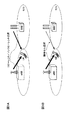
まず、下りリンクのCoMP送信について説明する。下りリンクのCoMP送信としては、Coordinated scheduling/Coordinated beamformingと、Joint processingとがある。Coordinated scheduling/Coordinated beamformingは、1UEに対して1セルからのみ送信する方法であり、他セルからの干渉や他セルへの干渉を考慮して周波数/空間領域における無線リソースの割り当てを行う方法である。一方、Joint processingは、プリコーディングを適用する複数セル同時送信であり、図1Aに示すような、1UEに対して複数のセルから送信するJoint transmission(JT)と、図1Bに示すような、瞬時にセルを選択するDynamic Point Selection(DPS)とがある。
Hereinafter, embodiments of the present invention will be described in detail with reference to the accompanying drawings.
First, downlink CoMP transmission will be described. Downlink CoMP transmission includes coordinated scheduling / coordinated beamforming and joint processing. Coordinated scheduling / Coordinated beamforming is a method of transmitting to one UE from only one cell, and is a method of assigning radio resources in the frequency / space region in consideration of interference from other cells and interference to other cells. . On the other hand, joint processing is simultaneous transmission of a plurality of cells to which precoding is applied. A joint transmission (JT) transmitted from a plurality of cells to one UE as shown in FIG. 1A and an instantaneous transmission as shown in FIG. 1B. And Dynamic Point Selection (DPS) for selecting a cell.
CoMP送受信を実現する構成としては、図2A、2Bに示す場合が考えられる。図2Aは、無線基地局装置eNBとこの無線基地局装置eNBと光張り出し構成(光ファイバ)で接続された複数の遠隔無線装置(RRE:Remote Radio Equipment)とを含む構成(遠隔無線装置構成に基づく集中制御)を示している。図2Bは、無線基地局装置eNBの構成(独立基地局構成に基づく自律分散制御)を示している。本実施の形態における無線通信システムは、上記いずれの構成であっても適用可能である。 As a configuration for realizing CoMP transmission / reception, the case shown in FIGS. 2A and 2B can be considered. FIG. 2A shows a configuration (remote radio device configuration) including a radio base station device eNB and a plurality of remote radio devices (RRE: Remote Radio Equipment) connected to the radio base station device eNB by an optical overhang configuration (optical fiber). Based centralized control). FIG. 2B shows the configuration of the radio base station apparatus eNB (autonomous distributed control based on the independent base station configuration). The wireless communication system in the present embodiment is applicable to any of the above configurations.
図2Aに示す構成(RRE構成)においては、遠隔無線装置RRE1、RRE2(送信ポイント)を無線基地局装置eNBで集中的に制御する。RRE構成では、複数のRREのベースバンド信号処理及び制御を行う無線基地局装置eNB(集中基地局)と各セル(RRE)との間が光ファイバを用いたベースバンド信号で接続される。このため、セル間の無線リソース制御を集中基地局において一括して行うことができる。すなわち、独立基地局構成で問題となる無線基地局装置間のシグナリングの遅延やオーバヘッドの問題が小さく、セル間の高速な無線リソース制御が比較的容易となる。したがって、RRE構成においては、下りリンクでは、複数セル同時送信のような高速なセル間の信号処理を用いる方法に適している。本明細書においては、RREについても無線基地局装置とする。 In the configuration shown in FIG. 2A (RRE configuration), the remote radio apparatuses RRE1 and RRE2 (transmission points) are centrally controlled by the radio base station apparatus eNB. In the RRE configuration, a radio base station apparatus eNB (concentrated base station) that performs baseband signal processing and control of a plurality of RREs and each cell (RRE) are connected by a baseband signal using an optical fiber. For this reason, radio resource control between cells can be performed collectively in a centralized base station. That is, the problem of signaling delay and overhead between radio base station apparatuses which are problems in the independent base station configuration is small, and high-speed radio resource control between cells is relatively easy. Therefore, the RRE configuration is suitable for a method using high-speed signal processing between cells such as simultaneous transmission of a plurality of cells in the downlink. In this specification, RRE is also assumed to be a radio base station apparatus.
一方、図2Bに示す構成においては、複数の無線基地局装置eNB(又はRRE)(送信ポイント)でそれぞれスケジューリングなどの無線リソース割り当て制御を行う。この場合においては、セル1の無線基地局装置eNBとセル2の無線基地局装置eNBとの間のX2インターフェースで必要に応じてタイミング情報やスケジューリングなどの無線リソース割り当て情報をいずれかの無線基地局装置に送信して、セル間の協調を行う。
On the other hand, in the configuration illustrated in FIG. 2B, radio resource allocation control such as scheduling is performed in each of a plurality of radio base station apparatuses eNB (or RRE) (transmission points). In this case, the radio resource allocation information such as timing information and scheduling is transmitted to any one of the radio base stations as necessary in the X2 interface between the radio base station apparatus eNB of the
上記CoMPを適用する環境においては、特にDPSを適用する環境においては、ハイブリッドARQ(HARQ)制御は、送信ポイント毎に独立に行われることになる。このようにHARQ制御が送信ポイント毎に行われる場合、以下のような問題が考えられる。 In an environment where CoMP is applied, particularly in an environment where DPS is applied, hybrid ARQ (HARQ) control is performed independently for each transmission point. When HARQ control is performed for each transmission point in this way, the following problems can be considered.
図3は、本実施の形態に係る再送制御法を説明するための図である。ここでは、送信ポイントが2つである(TP#0,TP#1)DPS−CoMP環境でのHARQ制御を説明する。図3において、データが送信されたサブフレームを斜線で示し、ユーザ端末で誤りなく受信できたサブフレームを○とし、ユーザ端末で誤りと判定されたサブフレームを×と表記し、再送がなされたサブフレームにR印を付した。
FIG. 3 is a diagram for explaining the retransmission control method according to the present embodiment. Here, HARQ control in a DPS-CoMP environment with two transmission points (
図3Aに示すように、サブフレーム#0,#1では、チャネル品質の良い送信ポイントTP#0からデータを送信し、ユーザ端末で誤りなく受信される。サブフレーム#2では、送信ポイントTP#1のチャネル品質が良くなったのでセルを切り替えてTP#1からデータを送信する。このとき、ユーザ端末ではデータに誤りがあると判定され、無線基地局装置に再送を要求する。また、サブフレーム#3では、送信ポイントTP#0のチャネル品質が良くなったのでセルを切り替えて送信ポイントTP#0からデータを送信する。このとき、ユーザ端末ではデータに誤りがあることが分かり、無線基地局装置に再送を要求する。
As shown in FIG. 3A, in
この場合において、送信ポイントTP#0の再送パケットは、サブフレーム#3の8サブフレーム後のサブフレーム#11で送信される。このサブフレーム#11における瞬時受信品質は、送信ポイント#0の方が良いので、送信ポイント#0から送信ポイントTP#0の再送パケットを送信することができる。しかしながら、送信ポイントTP#1の再送パケットは、サブフレーム#2の8サブフレーム後のサブフレーム#10で送信されるが、このサブフレーム#10における瞬時受信品質は、他の送信ポイントである送信ポイント#0の方が良いので、サブフレーム#10では送信ポイントTP#1の再送パケットを送信することができない。
In this case, the retransmission packet at transmission
そこで、本発明においては、再送制御を送信ポイント毎に行うのではなく、複数の送信ポイントの再送制御を共通化して行う。本発明に係る再送制御方法の第1の方法は、異なる送信ポイントから同一ユーザ端末に対してデータを送信している場合には、瞬時受信品質が高くなり、送信ポイントの切り替えが行われた際に再送パケットを送信する。すなわち、図3Aにおいては、サブフレーム#10以降で送信ポイントの切り替えが行われたサブフレーム#13で送信ポイント#1の再送パケットを送信する。言い換えると、送信ポイントTP#1の再送パケットは、誤りと判定されたサブフレームの再送サブフレーム位置より後段のサブフレームであって、送信ポイントTP#1が送信する最も早いサブフレームで送信される。このように送信ポイント間で共通化された再送制御を行うことにより、ユーザ端末における瞬時受信品質が高いときに再送パケットを送信することができる。
Therefore, in the present invention, retransmission control is not performed for each transmission point, but retransmission control for a plurality of transmission points is performed in common. The first method of the retransmission control method according to the present invention is that when data is transmitted from different transmission points to the same user terminal, the instantaneous reception quality becomes high and the transmission point is switched. Send a retransmission packet to. That is, in FIG. 3A, a retransmission packet of
本発明に係る再送制御方法の第2の方法は、図3Bに示すように、再送パケットを送信したいサブフレームにおいて、異なる送信ポイントから同一ユーザ端末に対してデータを送信したい場合に、強制的に再送パケットを送信する。すなわち、図3Bにおいては、サブフレーム#10で強制的に送信ポイント#1の再送パケットを送信する。このとき、送信ポイント#0は、瞬時受信品質が送信ポイント#1よりも良いにも拘わらず、データ送信がされない。このように送信ポイント間で共通化された再送制御を行うことにより、遅延なく再送パケットを送信することができる。
As shown in FIG. 3B, the second method of the retransmission control method according to the present invention compulsorily transmits data to the same user terminal from different transmission points in a subframe in which a retransmission packet is to be transmitted. Send a retransmission packet. That is, in FIG. 3B, the retransmission packet of
このような再送制御方法を行うこと(共通化された再送制御である旨)については、無線基地局装置からユーザ端末に通知される。例えば、この通知は、報知信号やRRCシグナリング等のハイヤレイヤシグナリングや、下り制御情報の送信により行われる。この通知は、共通化された再送制御である旨でも良く、CoMP環境における再送パケットの受信タイミングでも良く、予めユーザ端末に通知されていても良い。ユーザ端末は、無線基地局装置から前記通知を受信し、CoMP環境になったときに、上記第1の方法又は第2の方法で再送パケットを受信する。なお、システムがCoMP制御に入るかどうかについても、無線基地局装置からユーザ端末にハイヤレイヤシグナリングにより通知される。 The radio base station apparatus notifies the user terminal of performing such a retransmission control method (indicating that it is a common retransmission control). For example, this notification is performed by higher layer signaling such as a broadcast signal or RRC signaling, or transmission of downlink control information. This notification may be a common retransmission control, may be a reception timing of a retransmission packet in a CoMP environment, or may be notified to the user terminal in advance. The user terminal receives the notification from the radio base station apparatus, and receives the retransmission packet by the first method or the second method when the CoMP environment is established. Whether or not the system enters CoMP control is also notified from the radio base station apparatus to the user terminal by higher layer signaling.
本実施の形態では、複数の無線基地局装置においては、ユーザ端末が受信する下り信号の再送制御を無線基地局装置間で共通化して行い、複数の無線基地局装置の一つの無線基地局装置は、共通化された再送制御である旨をユーザ端末に通知する。例えば、2つの無線基地局装置でCoMP(DPS)制御を行う場合において、第1の無線基地局装置と第2の無線基地局装置は、それぞれCell#1とCell#2用の送信処理を制御する処理部を有する場合に、下り信号の再送制御を行う再送制御部22を共有する。一方で、下り制御信号、下りデータ信号、参照信号等の下り信号を無線リソースに対してマッピングするマッピング部26をセル毎に独立して有する構成とする(図4参照)。この場合において、共通化された再送制御である旨がハイヤレイヤシグナリング等によりユーザ端末に通知される。
In the present embodiment, in a plurality of radio base station apparatuses, retransmission control of downlink signals received by user terminals is performed in common among the radio base station apparatuses, and one radio base station apparatus of the plurality of radio base station apparatuses Notifies the user terminal that it is the common retransmission control. For example, when CoMP (DPS) control is performed by two radio base station apparatuses, the first radio base station apparatus and the second radio base station apparatus control transmission processes for
再送制御部22をセル間で共有することにより、再送制御部22で生成された再送信号を、第1の無線基地局装置のセル(Cell#1)と第2の無線基地局装置のセル(Cell#2)のいずれからでも送信可能となる。これにより、再送制御が一元化され、CoMP環境下において、高効率で再送パケット(再送信号)を送信することができる。
By sharing the
また、本実施の形態では、図4に示すように、異なるセル間において全ての送信処理を共通化せずに、下り制御信号等のマッピングを行うマッピング部26等のセル毎に異なる処理が必要となる構成についてはセル毎に独立して設けている。
Further, in the present embodiment, as shown in FIG. 4, different processing is required for each cell such as the
マッピング部26で多重を行う信号の例としては、データ信号(PDSCH(Physical Downlink Shared Channel))や、PDSCH、PUSCH(Physical Uplink Shared Channel)等の割り当て情報を通知するPDCCH信号や、高効率伝送を実現するため下りリンクの制御チャネルシンボル数CFI(Control channel Format Indicator)値を通知するPCFICH(Physical Control Format Indicator Channel)、上りリンクに対するACK/NACK情報を通知するPHICH(Physical Hybrid ARQ Indicator Channel)等の制御信号や、CRSやDM−RS(Demodulation Reference Signal)、CSI−RS(Channel State Information Reference Signal)等の参照信号が挙げられる。
Examples of signals multiplexed by the
下り制御信号(例えば、PDCCH信号)は、無線リソースにマッピングされて送信され、通信環境に応じてサブフレームの先頭1〜3OFDMシンボルまでに割当てられる。また、サブフレームの先頭1〜3OFDMシンボルには、セル固有の参照信号(CRS−RS等)も配置される。そのため、通信環境に応じて下り制御信号のマッピング位置がサブフレーム毎に変化すると共に、セル毎に異なる。また、参照信号については、セル固有の参照信号であるCRSやDM−RS、CSI−RS等がサブフレーム内に多重される。例えば、CRSの場合、CRSの多重位置がセルID(Identification)によって決定されるため、セル毎に異なる多重位置となる可能性がある。したがって、第1の無線基地局装置と第2の無線基地局装置は、マッピング部をセル毎に独立して設けて各セル単位で制御する。 A downlink control signal (for example, a PDCCH signal) is mapped to a radio resource and transmitted, and is allocated to the first 1 to 3 OFDM symbols of a subframe according to the communication environment. Also, cell-specific reference signals (such as CRS-RS) are also arranged in the first 1 to 3 OFDM symbols of the subframe. Therefore, the mapping position of the downlink control signal changes for each subframe according to the communication environment and differs for each cell. As for the reference signal, CRS, DM-RS, CSI-RS, etc., which are cell-specific reference signals, are multiplexed in the subframe. For example, in the case of CRS, since the multiplexing position of CRS is determined by the cell ID (Identification), there is a possibility that the multiplexing position differs for each cell. Therefore, the first radio base station apparatus and the second radio base station apparatus provide a mapping unit independently for each cell and control each cell unit.
なお、上記説明では、再送制御部22とマッピング部26について説明したが、図4に示すように、トランスポートブロック、チャネル符号化部21、データ変調部23等についてもセル間で共有して処理を共通化して行う構成とすることができる。一方で、マッピング後の処理であるIFFTを行うIFFT部27やCPを付与するCP挿入部28はセル毎に独立して設けて制御する構成とすることができる。
In the above description, the
セル間で共有する送信処理部(例えば、再送制御部22、トランスポートブロック、チャネル符号化部21、データ変調部23等)は、第1の無線基地局装置(Cell#1)と第2の無線基地局装置(Cell#2)の一方に設ける構成としてもよいし、双方に設ける構成としてもよい。再送制御部22等を双方の無線基地局装置に設ける場合には、処理自体を異なるセル間で共通化して制御する構成とすればよい。
A transmission processing unit (for example,
また、第1の無線基地局装置又は第2の無線基地局装置は、協調マルチポイント送信として瞬時セル選択方法(DPS)が適用される場合に、ユーザ端末10から送信される受信品質情報(各セルのCSI)に基づいて、送信が指示された所定のセルに対してマッピングを行う。例えば、第1の無線基地局装置又は第2の無線基地局装置は、ユーザ端末10から送信される受信品質を受信品質情報検出部25で検出し、当該受信品質情報に基づいて、下り信号をマッピングするセルを選択するセル選択部24を有している。セル選択部24は、ユーザ端末10から通知される受信SINR情報を用いて、受信SINRが高いセル(Cell#1又はCell#2)に対して、マッピングを行うように指示する。
In addition, the first radio base station apparatus or the second radio base station apparatus receives reception quality information (each of which is transmitted from the
このような構成において、第1の無線基地局装置からユーザ端末に送信した下り信号の再送信号を送信するタイミングで第2の無線基地局装置がユーザ端末に信号を送信する場合に、第1の無線基地局装置に送信ポイントの切り替えが行われた際に再送信号を送信する(第1の方法(図3A))。あるいは、第1の無線基地局装置からユーザ端末に送信した下り信号の再送信号を送信するタイミングで第2の無線基地局装置がユーザ端末に信号を送信する場合であっても、第1の無線基地局装置から再送信号を送信する(第2の方法(図3B))。 In such a configuration, when the second radio base station apparatus transmits a signal to the user terminal at the timing of transmitting the retransmission signal of the downlink signal transmitted from the first radio base station apparatus to the user terminal, When the transmission point is switched to the radio base station apparatus, a retransmission signal is transmitted (first method (FIG. 3A)). Alternatively, even if the second radio base station apparatus transmits a signal to the user terminal at the timing of transmitting a downlink retransmission signal transmitted from the first radio base station apparatus to the user terminal, the first radio A retransmission signal is transmitted from the base station apparatus (second method (FIG. 3B)).
このように、本実施の形態では、再送制御部をセル間で共有する構成とすることにより、CoMP環境下において高効率な再送制御を実現することができる。なお、上記説明においては、2つの無線基地局装置を例にして説明しているが、本発明はこれに限定されず、3つ以上の無線基地局装置で再送制御を共通化して行っても良い。 As described above, in this embodiment, by configuring the retransmission control unit to be shared between cells, highly efficient retransmission control can be realized in a CoMP environment. In the above description, two radio base station apparatuses are described as examples. However, the present invention is not limited to this, and retransmission control may be performed in common by three or more radio base station apparatuses. good.
以下、図5を参照しながら、ユーザ端末10及び無線基地局装置20から構成される無線通信システム1について説明する。ユーザ端末10及び無線基地局装置20は、LTE−Aをサポートしている。
Hereinafter, the
図5に示すように、無線通信システム1は、無線基地局装置20A、20Bと、この無線基地局装置20A、20Bと通信する複数のユーザ端末10A、10Bとを含んで構成されている。無線基地局装置20A、20Bは、上位局装置30と接続され、この上位局装置30は、コアネットワーク40と接続される。また、無線基地局装置20A、20Bは、有線接続又は無線接続により相互に接続されている。
As shown in FIG. 5, the
また、無線通信システム1は、第1の無線基地局装置20Aと第2の無線基地局装置20Bは、ユーザ端末10A、10Bに対して、周波数帯域が同じセル同士(セルC1とセルC2)で協調マルチポイント送信を行う。セルC1とセルC2は、カバレッジ範囲の少なくとも一部が重畳するか、一方のカバレッジ範囲が他方のカバレッジ範囲を含んでいる。
Further, in the
各ユーザ端末10A、10Bは、セルC1、C2においてそれぞれ無線基地局装置20A、20Bと通信を行うことができる。なお、上位局装置30には、例えば、アクセスゲートウェイ装置、無線ネットワークコントローラ(RNC)、モビリティマネジメントエンティティ(MME)等が含まれるが、これに限定されない。
Each
各ユーザ端末10A、10Bは、LTE端末及びLTE−A端末を含むが、以下においては、特段の断りがない限りユーザ端末として説明を進める。
Each of the
無線通信システム1においては、無線アクセス方式として、下りリンクについてはOFDMA(直交周波数分割多元接続)適用され、上りリンクについてはSC−FDMA(シングルキャリア−周波数分割多元接続)が適用される。なお、上りリンクの無線アクセス方式はこれに限定されない。OFDMAは、周波数帯域を複数の狭い周波数帯域(サブキャリア)に分割し、各サブキャリアにデータをマッピングして通信を行うマルチキャリア伝送方式である。SC−FDMAは、システム帯域をユーザ端末毎に1つ又は連続したリソースブロックからなる帯域に分割し、複数の端末が互いに異なる帯域を用いることで、端末間の干渉を低減するシングルキャリア伝送方式である。
In the
ここで、LTE−Aで規定される通信チャネル構成について説明する。下りリンクの通信チャネルは、各ユーザ端末10A、10Bで共有される下りデータチャネル(PDSCH)と、下りL1/L2制御チャネル(PDCCH、PCFICH、PHICH)とを有する。PDSCHにより、下りデータ及び上位制御信号が伝送される。PDCCHにより、PDSCHおよびPUSCHのスケジューリング情報等(下り制御情報)が伝送される。PCFICH(Physical Control Format Indicator Channel)により、PDCCHに用いるOFDMシンボル数が伝送される。PHICH(Physical Hybrid-ARQ Indicator Channel)により、PUSCHに対するHARQのACK/NACKが伝送される。
Here, a communication channel configuration defined in LTE-A will be described. The downlink communication channel includes a downlink data channel (PDSCH) shared by the
上りリンクの通信チャネルは、各ユーザ端末で共有される上りデータチャネルとしてのPUSCH(Physical Uplink Shared Channel)と、上りリンクの制御チャネルであるPUCCH(Physical Uplink Control Channel)とを有する。このPUSCHにより、送信データや上位制御情報が伝送される。また、PUCCHにより、下りリンクのチャネル品質情報(CQI)、ACK/NACKなどが伝送される。 The uplink communication channel includes a PUSCH (Physical Uplink Shared Channel) as an uplink data channel shared by each user terminal and a PUCCH (Physical Uplink Control Channel) that is an uplink control channel. Transmission data and higher control information are transmitted by this PUSCH. Further, downlink channel quality information (CQI), ACK / NACK, and the like are transmitted by PUCCH.
次に、図6を参照しながら、本実施の形態に係る無線基地局装置20の全体構成について説明する。なお、第1の無線基地局装置20A、第2の無線基地局装置20Bは、全体構成として同様とすることができるため、無線基地局装置20として説明する。また、ユーザ端末10A、10Bも、同様な構成であるため、ユーザ端末10として説明する。
Next, the overall configuration of radio
無線基地局装置20は、複数の送受信アンテナ201と、複数のアンプ部202と、複数の送受信部203と、ベースバンド信号処理部204と、呼処理部205と、伝送路インターフェース206とを備えている。下りリンクにより無線基地局装置20からユーザ端末10に送信される送信データは、上位局装置30から伝送路インターフェース206を介してベースバンド信号処理部204に入力される。
The radio
ベースバンド信号処理部204において、下りデータチャネルの信号は、PDCPレイヤの処理、送信データの分割・結合、RLC(Radio Link Control)再送制御の送信処理などのRLCレイヤの送信処理、MAC再送制御、例えば、再送制御(HARQ)の送信処理、スケジューリング、伝送フォーマット選択、チャネル符号化、逆高速フーリエ変換(IFFT:Inverse Fast Fourier Transform)処理、プリコーディング処理が行われる。また、下りリンク制御チャネルである物理下りリンク制御チャネルの信号に関しても、チャネル符号化や逆高速フーリエ変換などの送信処理が行われる。
In the baseband
また、ベースバンド信号処理部204は、報知チャネルにより、同一セルに接続するユーザ端末10に対して、各ユーザ端末10が無線基地局装置20との無線通信するための制御情報を通知する。当該セルにおける通信のための情報には、例えば、上りリンク又は下りリンクにおけるシステム帯域幅や、PRACH(Physical Random Access Channel)におけるランダムアクセスプリアンブルの信号を生成するためのルート系列の識別情報(Root Sequence Index)などが含まれる。
Also, the baseband
各送受信部203は、ベースバンド信号処理部204からアンテナ毎にプリコーディングして出力されたベースバンド信号を無線周波数帯に変換する。アンプ部202は、周波数変換された無線周波数信号を増幅して送受信アンテナ201により送信する。なお、送受信部203は、CoMP候補セル情報を受信する受信部、並びに送信電力情報、CoMPセル情報、隣接セル情報を送信すると共に、送信信号をCoMP送信する送信制御部を構成する。
Each transmission /
一方、上りリンクによりユーザ端末10から無線基地局装置20に送信されるデータについては、各送受信アンテナ201で受信された無線周波数信号がそれぞれ各アンプ部202で増幅され、各送受信部203で周波数変換されてベースバンド信号に変換され、ベースバンド信号処理部204に入力される。
On the other hand, for data transmitted from the
ベースバンド信号処理部204では、入力されたベースバンド信号に含まれる送信データに対して、FFT処理、IDFT処理、誤り訂正復号、MAC再送制御の受信処理、RLCレイヤ、PDCPレイヤの受信処理を行う。復号された信号は伝送路インターフェース206を介して上位局装置30に転送される。呼処理部205は、通信チャネルの設定や解放等の呼処理や、無線基地局装置20の状態管理や、無線リソースの管理を行う。
The baseband
次に、図7を参照しながら、本実施の形態に係るユーザ端末の全体構成について説明する。LTE端末もLTE−A端末もハードウエアの主要部構成は同じであるので、区別せずに説明する。ユーザ端末10は、複数の送受信アンテナ101と、複数のアンプ部102と、複数の送受信部103と、ベースバンド信号処理部104と、アプリケーション部105とを備えている。
Next, the overall configuration of the user terminal according to the present embodiment will be described with reference to FIG. Since the main parts of the hardware of the LTE terminal and the LTE-A terminal are the same, they will be described without distinction. The
下りリンクのデータについては、複数の送受信アンテナ101で受信した無線周波数信号がそれぞれアンプ部102で増幅され、送受信部103で周波数変換されてベースバンド信号に変換される。このベースバンド信号は、ベースバンド信号処理部104でFFT処理や、誤り訂正復号、再送制御の受信処理等がなされる。この下りリンクのデータの内、下りリンクのユーザデータは、アプリケーション部105に転送される。アプリケーション部105は、物理レイヤやMACレイヤより上位のレイヤに関する処理等を行う。また、下りリンクのデータの内、報知情報もアプリケーション部105に転送される。
For downlink data, radio frequency signals received by a plurality of transmission /
一方、上りリンクの送信データは、アプリケーション部105からベースバンド信号処理部104に入力される。ベースバンド信号処理部104においては、マッピング処理、再送制御(HARQ)の送信処理や、チャネル符号化、DFT処理、IFFT処理を行う。また、無線基地局装置20に通知するための各セルの受信品質情報を生成する処理を行う。送受信部103は、ベースバンド信号処理部104から出力されたベースバンド信号を無線周波数帯に変換する。その後、アンプ部102で増幅されて送受信アンテナ101より送信される。
On the other hand, uplink transmission data is input from the
図8は、本実施の形態に係る第1の無線基地局装置20A、第2の無線基地局装置20Bが有するベースバンド信号処理部204の機能ブロック図であり、主にベースバンド信号処理部204の送信処理の機能ブロックを示している。
FIG. 8 is a functional block diagram of the baseband
なお、図8では、一例として、光張り出し構成でデータ伝送が行われる第1の無線基地局装置20A(eNB)と第2の無線基地局装置20B(RRE)を示している。また、第1の無線基地局装置20Aと第2の無線基地局装置20Bは、同一周波数帯域のセル(Cell#1とCell#2)間でCoMP送受信を行う場合を示している。もちろん、無線基地局装置20の数や、各無線基地局装置が用いるセルの数はこれに限られない。
In FIG. 8, as an example, a first radio
第1の無線基地局装置20A(Cell#1)と第2の無線基地局装置20B(Cell#2)は、トランスポートブロックの生成、再送制御、データ変調を共通化して行う。また、下り制御信号等のマッピング、IFFT処理、CP挿入はセル毎に独立して制御する。
The first radio
図8では、チャネル符号化部21、再送制御部22、データ変調部23を第1の無線基地局装置20Aの一方に設け、マッピング部26、IFFT部27、CP挿入部28を第1の無線基地局装置20Aと第2の無線基地局装置20Bの双方に設ける場合を示している。もちろん、第1の無線基地局装置20Aと第2の無線基地局装置20Bの双方に、チャネル符号化部21、再送制御部22、データ変調部23を設け、これらの処理自体を異なるセル間で共通化して制御することも可能である。
In FIG. 8, a
チャネル符号化部21は、例えば、下り共有データチャネル(PDSCH)を、ユーザ毎にチャネル符号化する。再送制御部22は、ユーザ端末10から送信された上り信号に対して再送制御信号(ACK/NACK)を生成する。データ変調部23は、チャネル符号化されたユーザデータ等をユーザ毎に変調する。
For example, the
マッピング部26は、変調されたユーザデータ、下り制御信号等を無線リソースにマッピングする。IFFT部27は、下り制御信号や下り参照信号等を逆高速フーリエ変換して周波数領域の信号から時系列の信号に変換する。CP挿入部28は、下り制御信号の時系列信号にサイクリックプレフィックスを挿入する。なお、サイクリックプレフィクスは、マルチパス伝搬遅延の差を吸収するためのガードインターバルとして機能する。サイクリックプレフィックスが付加された送信データは、上記送受信部203に送出される。
The
また、第1の無線基地局装置20Aは、協調マルチポイント送信として瞬時セル選択方法(DPS)が適用される場合に、下り制御信号等をマッピングするセルを選択するセル選択部24を有している。セル選択部24は、ユーザ端末10から送信される受信品質情報(各セルのCSI)を受信品質情報検出部25で検出し、当該受信品質情報に基づいて、適切なセルを選択する。
In addition, the first radio
以下に、無線通信システムにおいて、ユーザ端末10に対して、第1の無線基地局装置20A(Cell#1)と第2の無線基地局装置20B(Cell#2)間でCoMP送信を行う場合について説明する。
Hereinafter, in the radio communication system, CoMP transmission is performed between the first radio
まず、第1の無線基地局装置20Aがハイヤレイヤシグナリングでユーザ端末10に対して、第1の無線基地局装置20A及び第2の無線基地局装置20BでDPS−CoMPモードに入ることを通知する。
First, the first radio
図3Aに示すように、ある送信期間(サブフレーム#0)において、Cell#1における受信品質が高く、セル選択部24はCell#1を選択する。これにより、第1の無線基地局装置20A(TP#0)は、ユーザ端末10に対してデータを送信する。サブフレーム#1においても第1の無線基地局装置20A(TP#0)がユーザ端末10に対してデータを送信する。サブフレーム#2においては、Cell#2における受信品質が高く、セル選択部24はCell#2を選択する。これにより、第2の無線基地局装置20B(TP#1)は、ユーザ端末10に対してデータを送信する。サブフレーム#3においては、Cell#1における受信品質が高く、セル選択部24はCell#1を選択する。これにより、第1の無線基地局装置20A(TP#0)は、ユーザ端末10に対してデータを送信する。
As shown in FIG. 3A, in a certain transmission period (subframe # 0), the reception quality in
サブフレーム#0,#1の送信パケットは、ユーザ端末10で誤りなく受信されACKがフィードバックされるが、サブフレーム#2,#3の送信パケットは、ユーザ端末10で誤りと判定され、NACKがフィードバックされる。このとき、再送制御部22は、送信ポイントTP#0の再送パケットについて、8サブフレーム後のサブフレーム#12で送信するように制御すると共に、再送制御部22は、送信ポイントTP#1の再送パケットについて、サブフレーム#11以降で送信ポイントの切り替えが行われたサブフレーム#14で送信ポイント#1の再送パケットを送信する(第1の方法)。このように送信ポイント間で共通化された再送制御を行うことにより、ユーザ端末における瞬時受信品質が高いときに再送パケットを送信することができる。
The transmission packets of
また、再送制御部22は、送信ポイントTP#0の再送パケットについて、サブフレーム#3の8サブフレーム後のサブフレーム#12で送信するように制御すると共に、送信ポイントTP#1の再送パケットについて、サブフレーム#2の8サブフレーム後のサブフレーム#11で再送パケットを送信するように制御する。このように送信ポイント間で共通化された再送制御を行うことにより、遅延なく再送パケットを送信することができる。
In addition, the
このような再送制御方法を行うこと(共通化された再送制御である旨)については、無線基地局装置からユーザ端末に通知される。例えば、この通知は、報知信号やRRCシグナリング等のハイヤレイヤシグナリングや、下り制御情報の送信により行われる。 The radio base station apparatus notifies the user terminal of performing such a retransmission control method (indicating that it is a common retransmission control). For example, this notification is performed by higher layer signaling such as a broadcast signal or RRC signaling, or transmission of downlink control information.
なお、図8では、第1の無線基地局装置20Aを無線基地局装置eNB、第2の無線基地局装置20Bを遠隔無線装置(RRE)として、上記図2Aで示した構成(遠隔無線装置構成に基づく集中制御)とする場合を示したが、もちろん本実施の形態は上記図2Bで示した構成(独立基地局構成に基づく自律分散制御)としてもよい。例えば、第1の無線基地局装置20A及び第2の無線基地局装置20Bを無線基地局装置eNBとして、X2インターフェースで接続することができる。この場合、図8において、第1の無線基地局装置20Aと第2の無線基地局装置20Bの双方に、チャネル符号化部21、再送制御部22、データ変調部23をそれぞれ設け、X2インターフェースを介してこれらの処理自体を異なるセル間で共通化して制御する構成とすることも可能である。
In FIG. 8, the first radio
以上、上述の実施形態を用いて本発明について詳細に説明したが、当業者にとっては、本発明が本明細書中に説明した実施形態に限定されるものではないということは明らかである。本発明は、特許請求の範囲の記載により定まる本発明の趣旨及び範囲を逸脱することなく修正及び変更態様として実施することができる。従って、本明細書の記載は、例示説明を目的とするものであり、本発明に対して何ら制限的な意味を有するものではない。 Although the present invention has been described in detail using the above-described embodiments, it is obvious to those skilled in the art that the present invention is not limited to the embodiments described in this specification. The present invention can be implemented as modified and changed modes without departing from the spirit and scope of the present invention defined by the description of the scope of claims. Therefore, the description of the present specification is for illustrative purposes and does not have any limiting meaning to the present invention.
1 移動通信システム
10 ユーザ端末
20 無線基地局装置
30 上位局装置
40 コアネットワーク
21 チャネル符号化部
22 再送制御部
23 データ変調部
24 セル選択部
25 受信品質情報検出部
26 マッピング部
27 IFFT部
28 CP挿入部
101 送受信アンテナ
102 アンプ部
103 送受信部
104 ベースバンド信号処理部
105 アプリケーション部
201 送受信アンテナ
202 アンプ部
203 送受信部
204 ベースバンド信号処理部
205 呼処理部
206 伝送路インターフェース
DESCRIPTION OF
Claims (9)
ユーザ端末に対して、協調マルチポイント送信を行う第1の無線基地局装置と第2の無線基地局装置を有し、
下り信号の送信ポイントとして前記第1の無線基地局装置と前記第2の無線基地局装置のいずれか一方が受信品質情報に基づいて選択されるダイナミックポイント選択(DPS)が適用され、
前記第1の無線基地局装置からの下り信号の再送信号を送信するタイミングで、前記第2の無線基地局装置が前記送信ポイントとして選択されている場合、前記第1の無線基地局装置は、前記送信ポイントが前記第1の無線基地局装置に切り替えられるまで、前記再送信号の送信を待つことを特徴とする無線通信システム。 A wireless communication system to which cooperative multipoint transmission is applicable,
A first radio base station apparatus and a second radio base station apparatus that perform cooperative multipoint transmission to a user terminal,
Dynamic point selection (DPS) in which either one of the first radio base station apparatus or the second radio base station apparatus is selected based on reception quality information is applied as a transmission point of a downlink signal,
When the second radio base station apparatus is selected as the transmission point at the timing of transmitting a retransmission signal of a downlink signal from the first radio base station apparatus, the first radio base station apparatus A wireless communication system, which waits for transmission of the retransmission signal until the transmission point is switched to the first wireless base station device .
ユーザ端末に対して、協調マルチポイント送信を行う第1の無線基地局装置と第2の無線基地局装置を有し、
下り信号の送信ポイントとして前記第1の無線基地局装置と前記第2の無線基地局装置のいずれか一方が受信品質情報に基づいて選択されるダイナミックポイント選択(DPS)が適用され、
前記第1の無線基地局装置からの下り信号の再送信号を送信するタイミングで、前記第2の無線基地局装置が前記送信ポイントとして選択されている場合、前記第1の無線基地局装置は、前記送信ポイントが前記第1の無線基地局装置に切り替えられるまで待たずに、前記タイミングで前記再送信号を送信することを特徴とする無線通信システム。 A wireless communication system to which cooperative multipoint transmission is applicable,
A first radio base station apparatus and a second radio base station apparatus that perform cooperative multipoint transmission to a user terminal,
Dynamic point selection (DPS) in which either one of the first radio base station apparatus or the second radio base station apparatus is selected based on reception quality information is applied as a transmission point of a downlink signal,
When the second radio base station apparatus is selected as the transmission point at the timing of transmitting a retransmission signal of a downlink signal from the first radio base station apparatus, the first radio base station apparatus The wireless communication system , wherein the retransmission signal is transmitted at the timing without waiting until the transmission point is switched to the first wireless base station device .
ダイナミックポイント選択(DPS)により下り信号の送信ポイントとして前記第1の無線基地局装置が受信品質情報に基づいて選択される場合に、前記ユーザ端末に対する下り信号を送信する送信部と、
前記下り信号の再送制御を行う再送制御部と、を具備し、
前記再送制御部は、前記第1の無線基地局装置からの下り信号の再送信号を送信するタイミングで、前記第2の無線基地局装置が前記送信ポイントとして選択されている場合、前記第1の無線基地局装置は、前記送信ポイントが前記第1の無線基地局装置に切り替えられるまで、前記再送信号の送信を待つことを特徴とする第1の無線基地局装置。 A first radio base station apparatus that performs cooperative multipoint transmission in cooperation with a second radio base station apparatus for a user terminal,
A transmitter that transmits a downlink signal to the user terminal when the first radio base station apparatus is selected based on reception quality information as a downlink signal transmission point by dynamic point selection (DPS);
A retransmission control unit that performs retransmission control of the downlink signal ,
The retransmission control unit, when the second radio base station apparatus is selected as the transmission point at a timing of transmitting a downlink retransmission signal from the first radio base station apparatus, The radio base station apparatus waits for transmission of the retransmission signal until the transmission point is switched to the first radio base station apparatus.
ダイナミックポイント選択(DPS)により下り信号の送信ポイントとして前記第1の無線基地局装置が受信品質情報に基づいて選択される場合に、前記ユーザ端末に対する下り信号を送信する送信部と、
前記下り信号の再送制御を行う再送制御部と、を具備し、
前記再送制御部は、前記第1の無線基地局装置からの下り信号の再送信号を送信するタイミングで、前記第2の無線基地局装置が前記送信ポイントとして選択されている場合、前記第1の無線基地局装置は、前記送信ポイントが前記第1の無線基地局装置に切り替えられるまで待たずに、前記タイミングで前記再送信号を送信することを特徴とする第1の無線基地局装置。 A first radio base station apparatus that performs cooperative multipoint transmission in cooperation with a second radio base station apparatus for a user terminal,
A transmitter that transmits a downlink signal to the user terminal when the first radio base station apparatus is selected based on reception quality information as a downlink signal transmission point by dynamic point selection (DPS);
A retransmission control unit that performs retransmission control of the downlink signal,
The retransmission control unit, when the second radio base station apparatus is selected as the transmission point at a timing of transmitting a downlink retransmission signal from the first radio base station apparatus, The radio base station apparatus transmits the retransmission signal at the timing without waiting until the transmission point is switched to the first radio base station apparatus.
下り信号の送信ポイントとして前記第1の無線基地局装置と前記第2の無線基地局装置のいずれか一方が受信品質情報に基づいて選択されるダイナミックポイント選択(DPS)が適用され、
前記第1の無線基地局装置からの下り信号の再送信号を送信するタイミングで、前記第2の無線基地局装置が前記送信ポイントとして選択されている場合、前記第1の無線基地局装置は、前記送信ポイントが前記第1の無線基地局装置に切り替えられるまで、前記再送信号の送信を待つことを特徴とする再送制御方法。 A retransmission control method in a radio communication system that includes a first radio base station apparatus and a second radio base station apparatus that perform cooperative multipoint transmission to a user terminal, and to which cooperative multipoint transmission is applicable,
Dynamic point selection (DPS) in which either one of the first radio base station apparatus or the second radio base station apparatus is selected based on reception quality information is applied as a transmission point of a downlink signal,
When the second radio base station apparatus is selected as the transmission point at the timing of transmitting a retransmission signal of a downlink signal from the first radio base station apparatus, the first radio base station apparatus A retransmission control method characterized by waiting for transmission of the retransmission signal until the transmission point is switched to the first radio base station apparatus .
下り信号の送信ポイントとして前記第1の無線基地局装置と前記第2の無線基地局装置のいずれか一方が受信品質情報に基づいて選択されるダイナミックポイント選択(DPS)が適用され、
前記第1の無線基地局装置からの下り信号の再送信号を送信するタイミングで、前記第2の無線基地局装置が前記送信ポイントとして選択されている場合、前記第1の無線基地局装置は、前記送信ポイントが前記第1の無線基地局装置に切り替えられるまで待たずに、前記タイミングで前記再送信号を送信することを特徴とする再送制御方法。 A retransmission control method in a radio communication system that includes a first radio base station apparatus and a second radio base station apparatus that perform cooperative multipoint transmission to a user terminal, and to which cooperative multipoint transmission is applicable,
Dynamic point selection (DPS) in which either one of the first radio base station apparatus or the second radio base station apparatus is selected based on reception quality information is applied as a transmission point of a downlink signal,
When the second radio base station apparatus is selected as the transmission point at the timing of transmitting a retransmission signal of a downlink signal from the first radio base station apparatus, the first radio base station apparatus The retransmission control method , wherein the retransmission signal is transmitted at the timing without waiting until the transmission point is switched to the first radio base station apparatus .
Priority Applications (5)
| Application Number | Priority Date | Filing Date | Title |
|---|---|---|---|
| JP2012170258A JP6030882B2 (en) | 2012-07-31 | 2012-07-31 | Radio communication system, radio base station apparatus, and retransmission control method |
| PCT/JP2013/066695 WO2014021009A1 (en) | 2012-07-31 | 2013-06-18 | Wireless communication system, wireless base stations and retransmission control method |
| US14/417,799 US9629141B2 (en) | 2012-07-31 | 2013-06-18 | Radio communication system, radio base station apparatus and retransmission control method |
| CN201380039275.XA CN104488310A (en) | 2012-07-31 | 2013-06-18 | Wireless communication system, wireless base stations and retransmission control method |
| US15/450,285 US20170237473A1 (en) | 2012-07-31 | 2017-03-06 | Radio communication system, radio base station apparatus and retransmission control method |
Applications Claiming Priority (1)
| Application Number | Priority Date | Filing Date | Title |
|---|---|---|---|
| JP2012170258A JP6030882B2 (en) | 2012-07-31 | 2012-07-31 | Radio communication system, radio base station apparatus, and retransmission control method |
Publications (2)
| Publication Number | Publication Date |
|---|---|
| JP2014030133A JP2014030133A (en) | 2014-02-13 |
| JP6030882B2 true JP6030882B2 (en) | 2016-11-24 |
Family
ID=50027699
Family Applications (1)
| Application Number | Title | Priority Date | Filing Date |
|---|---|---|---|
| JP2012170258A Expired - Fee Related JP6030882B2 (en) | 2012-07-31 | 2012-07-31 | Radio communication system, radio base station apparatus, and retransmission control method |
Country Status (4)
| Country | Link |
|---|---|
| US (2) | US9629141B2 (en) |
| JP (1) | JP6030882B2 (en) |
| CN (1) | CN104488310A (en) |
| WO (1) | WO2014021009A1 (en) |
Families Citing this family (4)
| Publication number | Priority date | Publication date | Assignee | Title |
|---|---|---|---|---|
| WO2017069559A1 (en) | 2015-10-21 | 2017-04-27 | 엘지전자 주식회사 | Method for transmitting ack/nack response for broadcast signal/multicast signal in wireless communication system, and device therefor |
| EP3567953A4 (en) * | 2017-01-06 | 2020-08-19 | NTT DoCoMo, Inc. | User terminal and wireless communication method |
| CN108809532A (en) | 2017-05-05 | 2018-11-13 | 华为技术有限公司 | A kind of data transmission method, device and system |
| WO2019097705A1 (en) * | 2017-11-17 | 2019-05-23 | 株式会社Nttドコモ | Communication device and communication method |
Family Cites Families (6)
| Publication number | Priority date | Publication date | Assignee | Title |
|---|---|---|---|---|
| KR101162003B1 (en) * | 2008-10-28 | 2012-07-03 | 후지쯔 가부시끼가이샤 | Wireless base station device using cooperative harq communication method, wireless terminal device, wireless communication system, and wireless communication method |
| JP5366847B2 (en) * | 2010-01-29 | 2013-12-11 | ソフトバンクモバイル株式会社 | COMMUNICATION SYSTEM, BASE STATION DEVICE, COMMUNICATION TERMINAL, AND COMMUNICATION CONTROL METHOD |
| JP2013168695A (en) * | 2010-06-08 | 2013-08-29 | Mitsubishi Electric Corp | Radio communication system |
| US20120163357A1 (en) * | 2010-12-24 | 2012-06-28 | Electronics And Telecommunications Research Institute | Method of retransmitting and receiving packets in heterogeneous network environment |
| US9084242B2 (en) * | 2011-08-15 | 2015-07-14 | Texas Instruments Incorporated | On transparency of CoMP |
| US9049730B2 (en) * | 2011-11-14 | 2015-06-02 | Qualcomm Incorporated | Uplink data transmission with interference mitigation |
-
2012
- 2012-07-31 JP JP2012170258A patent/JP6030882B2/en not_active Expired - Fee Related
-
2013
- 2013-06-18 WO PCT/JP2013/066695 patent/WO2014021009A1/en active Application Filing
- 2013-06-18 CN CN201380039275.XA patent/CN104488310A/en active Pending
- 2013-06-18 US US14/417,799 patent/US9629141B2/en not_active Expired - Fee Related
-
2017
- 2017-03-06 US US15/450,285 patent/US20170237473A1/en not_active Abandoned
Also Published As
| Publication number | Publication date |
|---|---|
| US20170237473A1 (en) | 2017-08-17 |
| JP2014030133A (en) | 2014-02-13 |
| US20150304992A1 (en) | 2015-10-22 |
| WO2014021009A1 (en) | 2014-02-06 |
| US9629141B2 (en) | 2017-04-18 |
| CN104488310A (en) | 2015-04-01 |
Similar Documents
| Publication | Publication Date | Title |
|---|---|---|
| EP2916585B1 (en) | Transmission and reception of reference signals in a wireless communication system comprising a plurality of base stations | |
| JP5325928B2 (en) | Channel state information notification method, radio base station apparatus, user terminal, and radio communication system | |
| JP5437310B2 (en) | Radio base station apparatus, mobile terminal apparatus, radio communication method, and radio communication system | |
| US9742534B2 (en) | Radio communication method, radio communication system, radio base station and user terminal | |
| JP5612770B2 (en) | Radio communication system, radio communication method, radio base station apparatus, and user terminal | |
| WO2016017356A1 (en) | User terminal, wireless base station, and wireless communication method | |
| JP2013236340A (en) | Radio communication system, radio base station device, user terminal and communication control method | |
| WO2014069164A1 (en) | Wireless communication method, wireless communication system, wireless base station, and user terminal | |
| JP5820246B2 (en) | Radio communication system, radio communication method, radio base station apparatus, and user terminal | |
| WO2012153804A1 (en) | Wireless base station device, mobile terminal device, wireless communication method, and wireless communication system | |
| US20170237473A1 (en) | Radio communication system, radio base station apparatus and retransmission control method | |
| US11677521B2 (en) | User terminal, radio base station and radio communication method | |
| JP5828002B2 (en) | Radio communication system, radio base station apparatus, user terminal, and radio communication method | |
| JP6096253B2 (en) | User terminal, radio base station apparatus, radio communication system, and communication control method | |
| JP5529327B2 (en) | Channel state information notification method, radio base station apparatus, user terminal, and radio communication system | |
| EP3177091A1 (en) | Wireless base station, user terminal, and wireless communication method |
Legal Events
| Date | Code | Title | Description |
|---|---|---|---|
| A621 | Written request for application examination |
Free format text: JAPANESE INTERMEDIATE CODE: A621 Effective date: 20150728 |
|
| A131 | Notification of reasons for refusal |
Free format text: JAPANESE INTERMEDIATE CODE: A131 Effective date: 20160705 |
|
| A521 | Request for written amendment filed |
Free format text: JAPANESE INTERMEDIATE CODE: A523 Effective date: 20160823 |
|
| TRDD | Decision of grant or rejection written | ||
| A01 | Written decision to grant a patent or to grant a registration (utility model) |
Free format text: JAPANESE INTERMEDIATE CODE: A01 Effective date: 20161004 |
|
| A61 | First payment of annual fees (during grant procedure) |
Free format text: JAPANESE INTERMEDIATE CODE: A61 Effective date: 20161021 |
|
| R150 | Certificate of patent or registration of utility model |
Ref document number: 6030882 Country of ref document: JP Free format text: JAPANESE INTERMEDIATE CODE: R150 |
|
| LAPS | Cancellation because of no payment of annual fees |