JP6030629B2 - Multi-function catheter - Google Patents
Multi-function catheter Download PDFInfo
- Publication number
- JP6030629B2 JP6030629B2 JP2014501705A JP2014501705A JP6030629B2 JP 6030629 B2 JP6030629 B2 JP 6030629B2 JP 2014501705 A JP2014501705 A JP 2014501705A JP 2014501705 A JP2014501705 A JP 2014501705A JP 6030629 B2 JP6030629 B2 JP 6030629B2
- Authority
- JP
- Japan
- Prior art keywords
- sleeve
- catheter
- catheter according
- tube
- feeding tube
- Prior art date
- Legal status (The legal status is an assumption and is not a legal conclusion. Google has not performed a legal analysis and makes no representation as to the accuracy of the status listed.)
- Active
Links
Images


Classifications
-
- A—HUMAN NECESSITIES
- A61—MEDICAL OR VETERINARY SCIENCE; HYGIENE
- A61B—DIAGNOSIS; SURGERY; IDENTIFICATION
- A61B18/00—Surgical instruments, devices or methods for transferring non-mechanical forms of energy to or from the body
- A61B18/04—Surgical instruments, devices or methods for transferring non-mechanical forms of energy to or from the body by heating
- A61B18/12—Surgical instruments, devices or methods for transferring non-mechanical forms of energy to or from the body by heating by passing a current through the tissue to be heated, e.g. high-frequency current
- A61B18/14—Probes or electrodes therefor
- A61B18/1492—Probes or electrodes therefor having a flexible, catheter-like structure, e.g. for heart ablation
-
- A—HUMAN NECESSITIES
- A61—MEDICAL OR VETERINARY SCIENCE; HYGIENE
- A61B—DIAGNOSIS; SURGERY; IDENTIFICATION
- A61B5/00—Measuring for diagnostic purposes; Identification of persons
- A61B5/03—Detecting, measuring or recording fluid pressure within the body other than blood pressure, e.g. cerebral pressure; Measuring pressure in body tissues or organs
- A61B5/036—Detecting, measuring or recording fluid pressure within the body other than blood pressure, e.g. cerebral pressure; Measuring pressure in body tissues or organs by means introduced into body tracts
- A61B5/037—Measuring oesophageal pressure
-
- A—HUMAN NECESSITIES
- A61—MEDICAL OR VETERINARY SCIENCE; HYGIENE
- A61B—DIAGNOSIS; SURGERY; IDENTIFICATION
- A61B5/00—Measuring for diagnostic purposes; Identification of persons
- A61B5/08—Detecting, measuring or recording devices for evaluating the respiratory organs
-
- A—HUMAN NECESSITIES
- A61—MEDICAL OR VETERINARY SCIENCE; HYGIENE
- A61B—DIAGNOSIS; SURGERY; IDENTIFICATION
- A61B5/00—Measuring for diagnostic purposes; Identification of persons
- A61B5/145—Measuring characteristics of blood in vivo, e.g. gas concentration, pH value; Measuring characteristics of body fluids or tissues, e.g. interstitial fluid, cerebral tissue
- A61B5/14539—Measuring characteristics of blood in vivo, e.g. gas concentration, pH value; Measuring characteristics of body fluids or tissues, e.g. interstitial fluid, cerebral tissue for measuring pH
-
- A—HUMAN NECESSITIES
- A61—MEDICAL OR VETERINARY SCIENCE; HYGIENE
- A61B—DIAGNOSIS; SURGERY; IDENTIFICATION
- A61B5/00—Measuring for diagnostic purposes; Identification of persons
- A61B5/24—Detecting, measuring or recording bioelectric or biomagnetic signals of the body or parts thereof
- A61B5/25—Bioelectric electrodes therefor
- A61B5/279—Bioelectric electrodes therefor specially adapted for particular uses
- A61B5/296—Bioelectric electrodes therefor specially adapted for particular uses for electromyography [EMG]
-
- A—HUMAN NECESSITIES
- A61—MEDICAL OR VETERINARY SCIENCE; HYGIENE
- A61B—DIAGNOSIS; SURGERY; IDENTIFICATION
- A61B5/00—Measuring for diagnostic purposes; Identification of persons
- A61B5/24—Detecting, measuring or recording bioelectric or biomagnetic signals of the body or parts thereof
- A61B5/316—Modalities, i.e. specific diagnostic methods
- A61B5/389—Electromyography [EMG]
- A61B5/392—Detecting gastrointestinal contractions
-
- A—HUMAN NECESSITIES
- A61—MEDICAL OR VETERINARY SCIENCE; HYGIENE
- A61B—DIAGNOSIS; SURGERY; IDENTIFICATION
- A61B5/00—Measuring for diagnostic purposes; Identification of persons
- A61B5/68—Arrangements of detecting, measuring or recording means, e.g. sensors, in relation to patient
- A61B5/6846—Arrangements of detecting, measuring or recording means, e.g. sensors, in relation to patient specially adapted to be brought in contact with an internal body part, i.e. invasive
- A61B5/6847—Arrangements of detecting, measuring or recording means, e.g. sensors, in relation to patient specially adapted to be brought in contact with an internal body part, i.e. invasive mounted on an invasive device
- A61B5/6852—Catheters
-
- A—HUMAN NECESSITIES
- A61—MEDICAL OR VETERINARY SCIENCE; HYGIENE
- A61J—CONTAINERS SPECIALLY ADAPTED FOR MEDICAL OR PHARMACEUTICAL PURPOSES; DEVICES OR METHODS SPECIALLY ADAPTED FOR BRINGING PHARMACEUTICAL PRODUCTS INTO PARTICULAR PHYSICAL OR ADMINISTERING FORMS; DEVICES FOR ADMINISTERING FOOD OR MEDICINES ORALLY; BABY COMFORTERS; DEVICES FOR RECEIVING SPITTLE
- A61J15/00—Feeding-tubes for therapeutic purposes
- A61J15/0026—Parts, details or accessories for feeding-tubes
- A61J15/008—Sensor means, e.g. for sensing reflux, acidity or pressure
- A61J15/0084—Sensor means, e.g. for sensing reflux, acidity or pressure for sensing parameters related to the patient
-
- A—HUMAN NECESSITIES
- A61—MEDICAL OR VETERINARY SCIENCE; HYGIENE
- A61M—DEVICES FOR INTRODUCING MEDIA INTO, OR ONTO, THE BODY; DEVICES FOR TRANSDUCING BODY MEDIA OR FOR TAKING MEDIA FROM THE BODY; DEVICES FOR PRODUCING OR ENDING SLEEP OR STUPOR
- A61M25/00—Catheters; Hollow probes
-
- A—HUMAN NECESSITIES
- A61—MEDICAL OR VETERINARY SCIENCE; HYGIENE
- A61N—ELECTROTHERAPY; MAGNETOTHERAPY; RADIATION THERAPY; ULTRASOUND THERAPY
- A61N1/00—Electrotherapy; Circuits therefor
- A61N1/02—Details
- A61N1/04—Electrodes
- A61N1/05—Electrodes for implantation or insertion into the body, e.g. heart electrode
- A61N1/0517—Esophageal electrodes
-
- A—HUMAN NECESSITIES
- A61—MEDICAL OR VETERINARY SCIENCE; HYGIENE
- A61M—DEVICES FOR INTRODUCING MEDIA INTO, OR ONTO, THE BODY; DEVICES FOR TRANSDUCING BODY MEDIA OR FOR TAKING MEDIA FROM THE BODY; DEVICES FOR PRODUCING OR ENDING SLEEP OR STUPOR
- A61M25/00—Catheters; Hollow probes
- A61M2025/0001—Catheters; Hollow probes for pressure measurement
- A61M2025/0002—Catheters; Hollow probes for pressure measurement with a pressure sensor at the distal end
-
- A—HUMAN NECESSITIES
- A61—MEDICAL OR VETERINARY SCIENCE; HYGIENE
- A61M—DEVICES FOR INTRODUCING MEDIA INTO, OR ONTO, THE BODY; DEVICES FOR TRANSDUCING BODY MEDIA OR FOR TAKING MEDIA FROM THE BODY; DEVICES FOR PRODUCING OR ENDING SLEEP OR STUPOR
- A61M25/00—Catheters; Hollow probes
- A61M2025/0004—Catheters; Hollow probes having two or more concentrically arranged tubes for forming a concentric catheter system
- A61M2025/0006—Catheters; Hollow probes having two or more concentrically arranged tubes for forming a concentric catheter system which can be secured against axial movement, e.g. by using a locking cuff
-
- A—HUMAN NECESSITIES
- A61—MEDICAL OR VETERINARY SCIENCE; HYGIENE
- A61M—DEVICES FOR INTRODUCING MEDIA INTO, OR ONTO, THE BODY; DEVICES FOR TRANSDUCING BODY MEDIA OR FOR TAKING MEDIA FROM THE BODY; DEVICES FOR PRODUCING OR ENDING SLEEP OR STUPOR
- A61M25/00—Catheters; Hollow probes
- A61M2025/0008—Catheters; Hollow probes having visible markings on its surface, i.e. visible to the naked eye, for any purpose, e.g. insertion depth markers, rotational markers or identification of type
Description
本発明は、体に電流を供給するのに好適な新規のカテーテル、特に、カテーテルの細長いメインシャフトとは無関係に位置決めできる電極を有するカテーテルに関する。より詳細には、本発明は、電極を組み込む可動スリーブを含むカテーテルに関する。本発明はまた、1つ以上の電極を含む可動スリーブに、ならびに電極および関連の構成要素の構造の進化に関する。本発明はまた、診断的適用または治療的適用のために、体の治療部位に電極を位置決めする方法に関する。 The present invention relates to a novel catheter suitable for supplying electrical current to the body, and more particularly to a catheter having electrodes that can be positioned independently of the elongated main shaft of the catheter. More particularly, the present invention relates to a catheter that includes a movable sleeve that incorporates an electrode. The present invention also relates to a movable sleeve that includes one or more electrodes, and to the evolution of the structure of the electrodes and related components. The invention also relates to a method of positioning an electrode at a treatment site in the body for diagnostic or therapeutic applications.
診断的適用、測定的適用およびその他の医学的応用に使用される電極を含むカテーテルはよく知られており、これらカテーテルは複数の電極を含む(例えば、Silnyの米国特許第5,109,870号明細書)。電極を含むカテーテルは当業界で公知であるが、それらにはいくつもの欠点がある。 Catheters containing electrodes for use in diagnostic, measurement, and other medical applications are well known, and these catheters contain multiple electrodes (eg, Silny US Pat. No. 5,109,870). Specification). Although catheters containing electrodes are known in the art, they have a number of disadvantages.
国際公開第2006/024825号パンフレット(Hamdy)には、口や鼻を経由して患者の体内に挿入するカテーテルを含む、嚥下障害からの回復を支援するカテーテルと、本発明の装置に特に有用な適用とが開示されている。電極はカテーテルの細長いシャフトにあり、カテーテルが患者の体内で好適な位置にあるとき、電極は、咽頭電気刺激を加える位置にある。 WO 2006/024825 (Hampy) is particularly useful for catheters that assist in recovery from dysphagia, including catheters that are inserted into the patient's body via the mouth and nose, and the device of the present invention. Application is disclosed. The electrode is on the elongate shaft of the catheter, and when the catheter is in a suitable position within the patient's body, the electrode is in a position to apply pharyngeal electrical stimulation.
しかしながら、本発明人らは、Hamdyが開示しているカテーテルの正確な位置決めには問題が発生し得ることを見出した。カテーテルは2つの機能を満たす必要がある−第1に、カテーテルの細長いシャフトの内部ルーメンを経由して患者の胃に栄養を安全かつ効果的に補給すること、および第2に、カテーテルの細長いシャフトの外表面にある電極を介して口腔咽頭部の規定領域に電気刺激を与えることである。カテーテルの本体に両機能を組み込むことには利点があり、これは、患者の不快感を最小限にし、かつ既存の標準的治療と一致するため、従来の経鼻胃(NG)栄養管に取って代わり、かつ従来のNG管と同じ方法で患者に挿入できる。 However, the inventors have found that problems can arise with the precise positioning of the catheter disclosed by Hamdy. The catheter needs to fulfill two functions—firstly, feeding the patient's stomach safely and effectively via the inner lumen of the catheter's elongate shaft, and second, the elongate shaft of the catheter. Applying electrical stimulation to a defined region of the oropharynx through electrodes on the outer surface of the oropharynx. There are advantages to incorporating both functions into the body of the catheter, which minimizes patient discomfort and is consistent with existing standard therapies, so it can be used with conventional nasogastric (NG) feeding tubes. And can be inserted into a patient in the same way as a conventional NG tube.
しかしながら、本発明人らによって、定位置の電極には、いくつかの欠点があることが分かっている。カテーテルは、遠位端部が胃の中で正しく位置決めされて、栄養を安全かつ効果的に補給するための条件を満たすように、患者に挿入する必要がある。正しい挿入距離は患者の身長に応じて大幅に異なる可能性があり、かつ通常、患者毎に20cm以上異なり得る。対照的に、口腔咽頭部おける電極に最適な位置は、垂直距離で2〜3cmの範囲内である。それゆえ、カテーテルの細長いシャフトにある電極を確実に正しく位置決めするためには、患者の身長のばらつきに対応するために様々なサイズのカテーテルを必要とするか、または予想される最も身長の高い患者のために十分に長いカテーテルを設計して、電極を正しい位置にするために身長の低い患者に余分に挿入する必要があるかのいずれかである。これは、カテーテルの遠位端部が、胃のなかに留まらずに十二指腸へ続き、胃のなかで絡まって、効果的な栄養の補給または胃からの簡単な除去を妨げないようにする、または胃から下部食道へ再出現するという危険性を生じる。 However, the inventors have found that the fixed position electrode has several drawbacks. The catheter needs to be inserted into the patient so that the distal end is properly positioned in the stomach and meets the requirements for safe and effective supplementation of nutrients. The correct insertion distance can vary significantly depending on the height of the patient and can usually vary from patient to patient by 20 cm or more. In contrast, the optimal position for the electrode in the oropharynx is in the range of 2-3 cm in vertical distance. Therefore, to ensure correct positioning of the electrodes on the elongate shaft of the catheter, various size catheters are needed or expected to be the tallest patients to accommodate variations in patient height Either a sufficiently long catheter may be designed for this purpose, and an extra insertion must be made in a short patient to place the electrodes in the correct position. This prevents the distal end of the catheter from continuing into the duodenum without staying in the stomach and becoming entangled in the stomach, preventing effective nutritional supplementation or easy removal from the stomach, or There is a risk of reappearance from the stomach to the lower esophagus.
Hamdyらの発明の電気刺激および栄養補給の双方の機能を固定した位置で行うことはまた、カテーテルの内部ルーメンが、栄養補給物によって消散できない状態で詰まった場合に、カテーテル全体を交換する必要があるという欠点がある。 Performing both the electrical stimulation and nutritional functions of Hamdy et al.'S invention in a fixed position also requires that the entire catheter be replaced if the internal lumen of the catheter becomes clogged in a manner that cannot be resolved by the nutritional supplement. There is a drawback of being.
さらに、電気刺激による治療が完了しても、依然として、経腸栄養のためだけにカテーテルを適所に保持しておく必要があり得ることが明らかとなった。これは、患者の快適さの点または安全管理の面から望ましくない。これらの理由から、電気刺激機能性を取り除けるようにする一方、栄養補給機能性を適所に残せるようにすることが特に有利である。 Furthermore, it has become clear that even when electrical stimulation treatment is complete, it may still be necessary to hold the catheter in place just for enteral nutrition. This is undesirable in terms of patient comfort or safety management. For these reasons, it is particularly advantageous to be able to remove the electrical stimulation functionality while leaving the nutritional functionality in place.
本発明人らは、ここで、別個の可動な電極担持部品に電極を含むカテーテルが、体に電流を供給するのに使用される電極の正確な位置決めに大きな利益をもたらすと判断した。それゆえ、本発明は、細長いシャフトと;1つ以上の電極を組み込んだスリーブであって、スリーブの位置が調整可能であるように細長いシャフトに沿って可動であるスリーブと;スリーブが適所になるとスリーブを細長いシャフトに固定する手段とを含む、体に電気刺激を与えるためのカテーテルを提供する。 The inventors have now determined that a catheter that includes an electrode in a separate movable electrode carrier component provides significant benefits in the precise positioning of the electrode used to supply current to the body. Therefore, the present invention relates to an elongate shaft; a sleeve incorporating one or more electrodes, wherein the sleeve is movable along the elongate shaft so that the position of the sleeve is adjustable; A catheter for providing electrical stimulation to the body is provided that includes means for securing the sleeve to the elongate shaft.
それゆえ、本発明は、2つ以上の機能を単一のカテーテルに組み込むことを可能にしかつ各機能を個別に位置決めして最適化できるようにすることによって、現在のカテーテル設計に勝る利点を提供する。それゆえ、カテーテルは、少なくとも1つの治療または診断機能を組み込み得る細長いシャフトを含む。それゆえ、カテーテルは、細長いシャフトおよびスリーブの双方に少なくとも1つの治療または診断機能を含み得る。細長いシャフトは、経腸栄養の提供などの治療機能を有してもよく、およびスリーブは電気刺激電極を有する。カテーテルは、圧力センサーまたはpHセンサーなどの他の診断機能を組み込んでもよい。 Therefore, the present invention provides advantages over current catheter designs by allowing more than one function to be incorporated into a single catheter and allowing each function to be individually positioned and optimized. To do. Therefore, the catheter includes an elongate shaft that can incorporate at least one therapeutic or diagnostic function. Thus, the catheter may include at least one therapeutic or diagnostic function on both the elongate shaft and the sleeve. The elongate shaft may have a therapeutic function, such as providing enteral nutrition, and the sleeve has an electrostimulation electrode. The catheter may incorporate other diagnostic functions such as a pressure sensor or a pH sensor.
本発明のカテーテルはまた、いくつかの機能部品を、それらがもはや必要なくなると、またはそれらの機能性が損なわれる場合に、選択的に除去できるように構成し得る。例えば、カテーテルは、細長いシャフトが取り除かれるときに電極担持スリーブが体内に留まることができるように構成できる。 The catheter of the present invention may also be configured so that some functional components can be selectively removed when they are no longer needed or when their functionality is compromised. For example, the catheter can be configured such that the electrode carrying sleeve can remain in the body when the elongate shaft is removed.
細長いシャフトを体内に残してスリーブを取り除けるようにカテーテルを構成することも可能である。 It is also possible to configure the catheter so that the sleeve can be removed leaving the elongated shaft in the body.
2つ以上の機能を組み込む、本発明によるカテーテルの例は以下を含む。
刺激を与えるための電極を備えるスリーブと、与えられた刺激の効果を検出するセンサーを備える細長いシャフトとを含む電気刺激用カテーテル。それゆえ、カテーテルは、スリーブの電気刺激機能と、細長いシャフトの診断機能とを組み合わせて、刺激の効果を測定する。そのようなカテーテルは、細長いシャフトが可動であるように構成し得る。これにより、刺激点を動かさずに、いくつもの異なる位置での刺激の効果を評価できるようにする。あるいは、スリーブを動かすことによって刺激点を動かすことができる。
Examples of catheters according to the present invention that incorporate more than one function include:
An electrical stimulation catheter including a sleeve including an electrode for applying a stimulus and an elongated shaft including a sensor for detecting an effect of the applied stimulus. Therefore, the catheter combines the electrical stimulation function of the sleeve with the diagnostic function of the elongated shaft to measure the effect of stimulation. Such a catheter may be configured such that the elongate shaft is movable. Thus, it is possible to evaluate the effect of stimulation at a number of different positions without moving the stimulation point. Alternatively, the stimulation point can be moved by moving the sleeve.
1組の刺激用電極を備えるスリーブと、第2の組の刺激用電極を備える細長いシャフトとを含む電気刺激を与えるためのカテーテル。これは、必要に応じて刺激点間の距離を調整できるようにするだけでなく、必要な場合には1つの刺激点を固定して保持もできるという利点を有する。 A catheter for providing electrical stimulation comprising a sleeve with a set of stimulation electrodes and an elongate shaft with a second set of stimulation electrodes. This has the advantage that not only the distance between the stimulation points can be adjusted as required, but also one stimulation point can be fixed and held if necessary.
例えば圧力、EMG信号またはpHを測定するセンサーである電極を組み込むスリーブと、例えば圧力、EMG信号またはpHを測定するセンサーを備える細長いコア構造とを含む測定用カテーテル。この構成は、固定位置と使用者が制御する可変位置とで同時に同じパラメータを測定するか、または固定位置と使用者が制御する可変位置とで同時に2つの異なるパラメータを測定する可能性を提供する。この構成を使用する有用な応用の一例は、下部食道括約筋の強度の測定、およびそれとは別の、食道に沿った複数の点でのpHの測定である。 A measuring catheter comprising a sleeve incorporating an electrode, for example a sensor for measuring pressure, EMG signal or pH, and an elongated core structure comprising a sensor for measuring pressure, EMG signal or pH, for example. This configuration provides the possibility to measure the same parameter simultaneously at a fixed position and a user controlled variable position, or to measure two different parameters simultaneously at a fixed position and a user controlled variable position. . An example of a useful application using this configuration is the measurement of the strength of the lower esophageal sphincter and, alternatively, the measurement of pH at multiple points along the esophagus.
電気刺激を与えるために1つ以上の電極を組み込むスリーブと、圧力センサーを組み込む細長いシャフトとを含む、電気刺激を与えかつ圧力を測定するためのカテーテル。圧力センサーは細長いシャフト上に位置決めでき、それらを使用して上部食道括約筋の圧力を測定できるようにする。この構成は、使用者に、上部食道括約筋からの圧力の示度値によってカテーテルの遠位端部が上気道または食道のどちらにあったかを知らせること、および気道ではなく咽頭または食道への刺激用電極の正しい配置を容易にすることを助ける。 A catheter for providing electrical stimulation and measuring pressure, comprising a sleeve incorporating one or more electrodes to provide electrical stimulation and an elongated shaft incorporating a pressure sensor. Pressure sensors can be positioned on the elongate shaft, allowing them to be used to measure upper esophageal sphincter pressure. This configuration informs the user whether the distal end of the catheter was in the upper or esophagus by means of an indication of pressure from the upper esophageal sphincter, and an electrode for stimulation to the pharynx or esophagus rather than the airway Helps facilitate the correct placement of.
電気刺激を与えるために電極を備えるスリーブと、患者の胃まで延在できかつpHセンサーをその遠位端部に組み込むことができる細長いコア構造とを含む、電気刺激を与えかつpHを測定するための二部品カテーテルの形態のカテーテル。この構成は、使用者に、患者の胃からのpHの示度値によってカテーテルの遠位端部が気道または食道のどちらにあったかを知らせること、および気道ではなく咽頭または食道への刺激用電極の正しい配置を容易にすることを助ける。 To provide electrical stimulation and measure pH, including a sleeve with electrodes to provide electrical stimulation and an elongate core structure that can extend to the patient's stomach and incorporate a pH sensor at its distal end A catheter in the form of a two-part catheter. This configuration informs the user whether the distal end of the catheter was in the airway or esophagus by means of a pH reading from the patient's stomach, and the stimulation electrode to the pharynx or esophagus rather than the airway Helps facilitate correct placement.
別の例は、電気刺激を与えるために電極を備えるスリーブと、経鼻胃栄養管の形態の細長いシャフトとを含む、電気刺激を与えかつ栄養を補給するカテーテルである。このカテーテルは、嚥下障害、特に急性嚥下障害を治療するために使用できる一方、患者の胃への栄養の安全な補給も維持する。 Another example is a catheter that provides electrical stimulation and provides nutrition, including a sleeve with electrodes to provide electrical stimulation and an elongate shaft in the form of a nasogastric feeding tube. While this catheter can be used to treat dysphagia, particularly acute dysphagia, it also maintains a safe supply of nutrients to the patient's stomach.
それゆえ、本発明のカテーテルは、急性または慢性嚥下障害の治療のための咽頭刺激カテーテルとし得る。 Therefore, the catheter of the present invention can be a pharyngeal stimulation catheter for the treatment of acute or chronic dysphagia.
嚥下障害は、患者が嚥下困難である状態、すなわち飲み込むことができないことである。嚥下障害は、例えば、脳卒中、神経変性病、および脳腫瘍によって、または場合によっては呼吸器疾患などの他の共存症によって引き起こされ得る。嚥下障害は、脳卒中または外傷性脳損傷(TBI)後の急性神経障害によって生じる急性状態とし、かつ病院において管理され得る。嚥下障害はまた、持続性または慢性状態とし得る(最初の発生後6週間超の期間残って存在すると定義される)。これは、脳卒中またはTBI誘発欠陥から回復できないためであり、パーキンソン病などの進行性の神経変性病の特徴とし得るか、または脳性麻痺や多発性硬化症などの状態の特徴とし得る。この場合、管理は、ほとんどの場合、病院の外部で行われる。急性であるかまたは慢性であるかにかかわらず、嚥下障害は、主に食物および液体が気道に制御されずに入ることに起因する呼吸器感染の発生による、命にかかわる状態である。脳卒中後の嚥下障害は、嚥下障害のない脳卒中患者と比べると、吸引性肺炎が6倍増加する。 A dysphagia is a condition in which a patient has difficulty swallowing, i.e., unable to swallow. Dysphagia can be caused by, for example, stroke, neurodegenerative diseases, and brain tumors, or possibly other comorbidities such as respiratory diseases. Dysphagia is an acute condition caused by acute neuropathy after a stroke or traumatic brain injury (TBI) and can be managed in a hospital. Dysphagia can also be a persistent or chronic condition (defined as remaining for more than 6 weeks after first occurrence). This is because it is not possible to recover from a stroke or TBI-induced defect and may be characterized by progressive neurodegenerative diseases such as Parkinson's disease or by conditions such as cerebral palsy and multiple sclerosis. In this case, management is most often performed outside the hospital. Regardless of whether it is acute or chronic, dysphagia is a life-threatening condition primarily due to the occurrence of respiratory infections that result from the uncontrolled entry of food and fluid into the respiratory tract. Dysphagia after stroke increases aspiration pneumonia 6-fold compared to stroke patients without dysphagia.
本発明による咽頭刺激カテーテルは、急性嚥下障害または慢性嚥下障害のどちらの患者を治療するかに依存して、いくつかの異なる構成を有し得ることが想定される。例えば救急病院環境で、患者が脳卒中後の嚥下障害を示す場合、患者は、経腸栄養管による栄養補給も必要とする可能性がある。それゆえ、栄養補給能力と、治療的電気刺激を咽頭に与える能力とを組み合わせる装置の構成は、急性嚥下障害の患者には特に有利である。嚥下障害の治療および栄養補給のためのカテーテルのこの構成は、病院環境において使用され、栄養管を組み込んで、比較的長い期間(29日間まで)実施されることが想定される。慢性嚥下障害の患者を治療するのに特に好適な代替的な構成は、経腸栄養管を組み込む必要はないが、ケアの内容、すなわち、病院においてではなく地域密着型となる可能性を反映して、異なる機能条件を有する。この場合、細長いシャフトの主な機能は、電極担持スリーブを治療部位に配置するのを容易にすることである。 It is envisioned that the pharyngeal stimulation catheter according to the present invention may have a number of different configurations depending on whether patients with acute or chronic dysphagia are being treated. For example, in an emergency hospital environment, if a patient exhibits dysphagia after a stroke, the patient may also need nutritional supplementation with an enteral feeding tube. Therefore, a device configuration that combines the ability to supply nutrition and the ability to provide therapeutic electrical stimulation to the pharynx is particularly advantageous for patients with acute dysphagia. This configuration of catheters for the treatment and feeding of dysphagia is envisioned to be used in a hospital environment and to be implemented for a relatively long period (up to 29 days) incorporating a feeding tube. An alternative configuration that is particularly suitable for treating patients with chronic dysphagia does not need to incorporate an enteral feeding tube, but reflects the content of care, i.e. the potential for community-based rather than in the hospital. And have different functional conditions. In this case, the main function of the elongated shaft is to facilitate placement of the electrode carrying sleeve at the treatment site.
細長いシャフトが経鼻胃(NG)管である構成では、細長いシャフトは、その外部表面に視覚的な位置表示器を組み込み得る。細長いシャフトはまた、経腸栄養法セットとの係合に好適なコネクタを含み得る。 In configurations where the elongate shaft is a nasogastric (NG) tube, the elongate shaft may incorporate a visual position indicator on its outer surface. The elongate shaft may also include a connector suitable for engagement with an enteral nutrition set.
しかしながら、当業者には明白なように、および上述の通り、本発明のカテーテルは、他の治療または診断的適用においても、特に、細長いシャフトの位置に対して電極の位置を調整することが望ましいときにおよび/または治療または診断部位に電極を正確に位置決めすることが望ましいときに有用であることが想定される。 However, as will be apparent to those skilled in the art and as described above, it is desirable that the catheter of the present invention adjusts the position of the electrode relative to the position of the elongate shaft, particularly in other therapeutic or diagnostic applications. It is envisioned that it is sometimes useful and / or when it is desirable to accurately position the electrode at the treatment or diagnostic site.
カテーテルの細長いシャフトまたはスリーブに組み込まれ得る機能性の種類の例は、限定されるものではないが、電極、センサー、トランスデューサー、ワイヤ、導電性材料、活性薬品表面コーティング、潤滑材、バルーンまたはステントを含む。 Examples of the types of functionality that can be incorporated into an elongate shaft or sleeve of a catheter include, but are not limited to, electrodes, sensors, transducers, wires, conductive materials, active drug surface coatings, lubricants, balloons or stents including.
スリーブの寸法は、細長いシャフトに対して動くことができるような寸法である。スリーブの寸法は、カテーテルが体内の適所にあるとき、スリーブが体の外まで延在するような寸法とし得る。これは、体の外側からスリーブの位置を調整できるようにするため、有利である。また、スリーブを展開または調整するためにカテーテルに別個の機構を必要とすることなく、医療従事者によってスリーブを位置決めできることを意味する。それゆえ、スリーブの位置を手動で調整できる。 The dimension of the sleeve is such that it can move relative to the elongated shaft. The sleeve dimensions can be such that when the catheter is in place in the body, the sleeve extends out of the body. This is advantageous because it allows the position of the sleeve to be adjusted from outside the body. It also means that the sleeve can be positioned by a medical practitioner without requiring a separate mechanism on the catheter to deploy or adjust the sleeve. Therefore, the position of the sleeve can be adjusted manually.
一般に、スリーブは、ポリウレタン、PVC、ポリアミド、シリコーンまたはこれらの等価材料で作製された実質的に透明の可撓性の管である。スリーブの寸法は、細長いシャフトに対して動かすことができるような寸法であるため、その内径のサイズは、細長いシャフトの外径よりも大きい。例えば、細長いシャフトが大人用の経鼻胃栄養管である場合、スリーブの寸法は、外径約5mmであり、内部ルーメンは直径3mm、および長さ約35〜45cmである。この構成は、急性嚥下障害の治療用の咽頭刺激カテーテルに特に好適である。当業者には、スリーブの寸法は、治療される患者集団に応じて変化し得ることが明白である。例えば、栄養管を8Fとし、およびスリーブを14Fとしてもよい。 Generally, the sleeve is a substantially transparent flexible tube made of polyurethane, PVC, polyamide, silicone, or equivalent materials. Since the dimensions of the sleeve are such that it can be moved relative to the elongate shaft, the size of its inner diameter is larger than the outer diameter of the elongate shaft. For example, if the elongate shaft is an adult nasogastric feeding tube, the sleeve dimensions are about 5 mm in outer diameter, the inner lumen is 3 mm in diameter, and about 35-45 cm in length. This configuration is particularly suitable for pharyngeal stimulation catheters for the treatment of acute dysphagia. It will be apparent to those skilled in the art that the dimensions of the sleeve can vary depending on the patient population being treated. For example, the feeding tube may be 8F and the sleeve may be 14F.
スリーブは、1つ以上の対のリング電極と、電極に接続されたスリーブの壁に沿って横方向に配置された導電性要素とを組み込み得る。スリーブの壁は、導電性要素(ワイヤ)用に予め形成されたルーメンを含み得る。それゆえ、スリーブは、多ルーメン押出によって形成され得る。そこで、スリーブは、ワイヤを適切なルーメンに挿入することによって、構成し得る。ワイヤは、例えばFEP(フッ素化エチレンプロピレン)などの絶縁材によって被覆し得る。 The sleeve may incorporate one or more pairs of ring electrodes and conductive elements disposed laterally along the wall of the sleeve connected to the electrodes. The wall of the sleeve may include a preformed lumen for the conductive element (wire). Therefore, the sleeve can be formed by multi-lumen extrusion. The sleeve can then be constructed by inserting the wire into the appropriate lumen. The wire may be covered with an insulating material such as FEP (fluorinated ethylene propylene).
スリーブはまた、装置、例えばY型コネクタを含んで、ワイヤを電気コネクタまで案内し得る。 The sleeve can also include a device, such as a Y-shaped connector, to guide the wire to the electrical connector.
スリーブは、細長いシャフト上を摺動するのを助けるように適合され得る。スリーブおよび/または細長いシャフトは、潤滑材での被覆、表面硬度の修正、表面特徴の組み込み、またはその他の方法によって修正し、患者の外側および内側にあるときの双方で、細長いシャフトの長さに沿ったスリーブの自由な相対運動を可能にし得る。 The sleeve may be adapted to help slide on the elongated shaft. The sleeve and / or elongate shaft may be modified by coating with a lubricant, modification of surface hardness, incorporation of surface features, or other methods to the length of the elongate shaft both when outside and inside the patient. It may allow free relative movement of the sleeves along.
スリーブの内側面は、その硬度、形状、仕上げまたはコーティングに対して修正を行って、その修正により、スリーブを細長いシャフトに配置するかまたはスリーブを位置決めしたシャフトに沿って動かすときの摩擦を最小限にするように、助けてもよい。 The inner surface of the sleeve is modified to its hardness, shape, finish or coating so that the modification minimizes friction when placing the sleeve on the elongate shaft or moving the sleeve along the positioned shaft May help you.
スリーブは位置表示器、例えば可視的表示器、例えばその表面上に印刷されたガイドまたは窓を有し、細長いシャフトに対するその位置決めを容易にし得る。 The sleeve may have a position indicator, such as a visual indicator, such as a guide or window printed on its surface, to facilitate its positioning relative to the elongated shaft.
カテーテルは、細長いシャフトを体内に残してスリーブを取り除くようにして、構成することが可能である。そのような構成は、急性嚥下障害の治療において特に有利であり、この場合、細長いシャフトが栄養管として機能する。 The catheter can be configured such that the sleeve is removed leaving the elongated shaft in the body. Such a configuration is particularly advantageous in the treatment of acute dysphagia, in which the elongated shaft functions as a feeding tube.
本発明の別の特徴は、スリーブの遠位端部の形状によって、患者の不快感を最小限にすることである。この形状は、段階的なまたは丸みを帯びた端部を含み、挿入または除去の最中にスリーブが組織を撹乱させないようにすることを保証し得る。 Another feature of the present invention is that the shape of the distal end of the sleeve minimizes patient discomfort. This shape may include a stepped or rounded end to ensure that the sleeve does not disturb the tissue during insertion or removal.
本発明の重要な特徴は、別個のスリーブおよび細長いシャフトを提供することによって単一のカテーテルを使用できるようにすることであり、そうでなければ2つ以上のカテーテルが必要となる。さらに、本発明は、可動スリーブおよび細長いシャフトを含むカテーテルと位置表示器とを提供し、位置表示器は、カテーテルを体内で正確に位置決めする手段を提供する。 An important feature of the present invention is that it allows a single catheter to be used by providing a separate sleeve and elongated shaft, otherwise more than one catheter is required. Furthermore, the present invention provides a catheter and a position indicator including a movable sleeve and an elongated shaft, the position indicator providing a means for accurately positioning the catheter within the body.
それゆえ、本発明によるカテーテルは、スリーブが細長いシャフト上で正しく位置決めされているときを示すように配置された位置表示器を含み得る。一般に、スリーブが位置表示器を含む;しかしながら、スリーブおよび細長いシャフトの双方が位置表示器を含む場合、有利とし得る。カテーテルは、スリーブが細長いシャフトに対して正しく配置されているため患者内の予め定められた位置にあるときを示すように配置された位置表示器を含み得る。 Therefore, a catheter according to the present invention may include a position indicator arranged to indicate when the sleeve is correctly positioned on the elongate shaft. In general, the sleeve includes a position indicator; however, it may be advantageous if both the sleeve and the elongate shaft include a position indicator. The catheter may include a position indicator positioned to indicate when the sleeve is in a predetermined position within the patient because it is properly positioned with respect to the elongate shaft.
本発明による位置表示器は、スリーブおよび/または細長いシャフトの外面に可視的なマーキングを、例えばスリーブの表面に、垂直および/または横方向の配置を示すためのガイドまたはスケールを含み得る。ガイドまたはスケールは、例えば、男性または女性、および患者の身長に基づいた垂直距離範囲など、治療される患者に応じていくつもの表示器を提供し得る。そのようなガイドまたはスケールは、スリーブの配置に基づき得る。好ましい実施形態では、挿入距離を特定する細長いシャフト上に印刷されたガイドと一致する、スリーブに印刷された窓がある。例えば、急性での使用のために構成された咽頭刺激カテーテルでは、窓から電極までの距離は14cm〜17cmの範囲にあり、電極が、カテーテル挿入時に患者内で正しい位置にあることを保証する。カテーテルは、2つ以上の位置表示器、例えば、任意選択で色分けされ得る2つ以上の窓を組み込んで、異なる応用および患者のサイズまたはカテーテル挿入ルート(経口的または経鼻的)に応えてもよい。 The position indicator according to the present invention may include a guide or scale for indicating a visible marking on the outer surface of the sleeve and / or elongate shaft, for example, a vertical and / or lateral arrangement on the surface of the sleeve. The guide or scale may provide a number of indicators depending on the patient being treated, for example, a male or female and a vertical distance range based on the patient's height. Such a guide or scale may be based on the placement of the sleeve. In a preferred embodiment, there is a window printed on the sleeve that matches the guide printed on the elongate shaft that specifies the insertion distance. For example, in a pharyngeal stimulation catheter configured for acute use, the distance from the window to the electrode is in the range of 14 cm to 17 cm, ensuring that the electrode is in the correct position in the patient at the time of catheter insertion. The catheter incorporates two or more position indicators, eg, two or more windows that can optionally be color coded, to meet different applications and patient sizes or catheter insertion routes (oral or nasal) Good.
当業者には、位置表示器は、電極を正しく配置するのを容易にするために、診断情報を提供する他のカテーテルの機能と組み合わせてもよいことが明白である。例えば咽頭刺激用のカテーテルは、スリーブおよび/または細長いシャフト上の可視的ガイドの形態の位置表示器、およびまた、患者の食道上部括約筋の高圧ゾーンを検出するための圧力センサーを組み込んでもよい。圧力センサーは、カテーテルのスリーブまたは細長いシャフトに組み込まれ得る。他の好適なセンサーは、CO2センサー、含水率センサーまたはpHセンサーを含む。 It will be apparent to those skilled in the art that the position indicator may be combined with other catheter functions that provide diagnostic information to facilitate correct placement of the electrodes. For example, a catheter for pharyngeal stimulation may incorporate a position indicator in the form of a visual guide on a sleeve and / or an elongated shaft, and also a pressure sensor for detecting the high pressure zone of the patient's upper esophageal sphincter. The pressure sensor may be incorporated into the catheter sleeve or elongate shaft. Other suitable sensors include a CO 2 sensor, a moisture sensor or a pH sensor.
本発明のカテーテルは、細長いシャフトに対して移動し得るスリーブを有し、カテーテルはまた、スリーブを適所に固定する手段を有する。この固定手段が可逆性である場合、有利とし得る。それゆえ、スリーブを細長いシャフト上の適所に固定した後、固定手段を解放して、スリーブの位置をさらに調整することおよび/またはスリーブまたは細長いシャフトを取り除くことが依然として可能である。固定手段は、患者への挿入前または後に係合し得る。有利には、固定手段はスリーブの近位端部に配置される。 The catheter of the present invention has a sleeve that is movable relative to the elongate shaft, and the catheter also has means for securing the sleeve in place. It may be advantageous if this fixing means is reversible. Therefore, after fixing the sleeve in place on the elongate shaft, it is still possible to release the fixing means to further adjust the position of the sleeve and / or remove the sleeve or elongate shaft. The securing means may be engaged before or after insertion into the patient. Advantageously, the securing means is arranged at the proximal end of the sleeve.
例えばクリップの形態の固定手段は、スリーブの一部を形成するか、またはそこに装着され得る。固定手段は、スリーブの近位端部に位置決めされ得る。しかしながら、特に咽頭刺激応用に関し、固定手段は、カテーテルが体内の適所にあるときに、体の外部、すなわちスリーブ/細長いシャフトの近位端部に配置されるクリップの形態とし得る。それゆえ、本発明のカテーテルは、細長いシャフトに対してスリーブの位置を固定するためのクリップを含み、前記クリップはカテーテルの近位端部に配置される。 The fixing means, for example in the form of a clip, can form part of or be attached to the sleeve. The securing means can be positioned at the proximal end of the sleeve. However, particularly for pharyngeal stimulation applications, the securing means may be in the form of a clip that is placed on the exterior of the body, ie, the proximal end of the sleeve / elongate shaft, when the catheter is in place in the body. Therefore, the catheter of the present invention includes a clip for fixing the position of the sleeve relative to the elongate shaft, said clip being located at the proximal end of the catheter.
理想的には、固定手段はまた、例えば、クリップがスリーブの近位端部に配置されているときにスリーブと細長いシャフトとの間のいかなる間隙も封止するように機能し、スリーブと細長いシャフトとの間での液体または材料の侵入を防止する。 Ideally, the securing means also functions to seal any gap between the sleeve and the elongate shaft, for example when the clip is positioned at the proximal end of the sleeve, the sleeve and the elongate shaft Prevent intrusion of liquids or materials between them.
スリーブは、適所に固定されていないとき、細長いシャフトの長さに沿って自由に動くことができる。有利なことには、固定手段は、スリーブの近位端部に位置決めされ得るので、カテーテルが体内に挿入されるときも操作者がアクセスしやすいままとなり得る。固定手段は、Y型コネクタ組立体の一部、それゆえ、スリーブがY型コネクタを組み込む場合はスリーブの一部を形成してもよく、例えば、スリーブの近位端部は、固定手段を組み込むコネクタに取り付けられてもよく、固定手段は細長いシャフト、例えばNG管に作用して、細長いシャフトに対するスリーブの位置を固定する。これにより、使用者は、スリーブに対してシャフトを動かすことができ、その後固定手段を係合してスリーブを固定する。コネクタはまた、ワイヤを好適な電気コネクタまで案内するための導管を組み込み得る。コネクタは、上述のようなY型コネクタの形態とし得る。そのようなコネクタ構成の例を図5に示す。 The sleeve is free to move along the length of the elongate shaft when not secured in place. Advantageously, the securing means may be positioned at the proximal end of the sleeve so that it remains accessible to the operator when the catheter is inserted into the body. The securing means may form part of the Y-connector assembly, and therefore the sleeve if the sleeve incorporates a Y-connector, for example, the proximal end of the sleeve incorporates the securing means It may be attached to the connector and the securing means acts on the elongate shaft, eg NG tube, to fix the position of the sleeve relative to the elongate shaft. This allows the user to move the shaft relative to the sleeve and then engages the securing means to secure the sleeve. The connector may also incorporate a conduit for guiding the wire to a suitable electrical connector. The connector may be in the form of a Y-type connector as described above. An example of such a connector configuration is shown in FIG.
あるいは、固定手段は、独立しているがY型コネクタに接続可能な形体とし得る。 Alternatively, the securing means may be in an independent but connectable form to the Y connector.
固定手段は、スリーブに固定されかつ例えばその内表面上の隆起またはその等価物によって細長いシャフトを把持することができる、可逆的に係合可能なクリップの形態を取り得る。固定手段はまた、Touhy−Borst弁と同様の方法で動作してもよく、それにより、スリーブ上のコネクタは、可逆的に圧縮され得る変形可能なOリングを含む。このようにして、Oリングの中心に延びる細長いシャフトを保持または解放することが可能である。可逆的に係合可能なクリップまたは固定手段はまた、細長いシャフトを把持するコレットの形態、またはシャフトを把持する干渉突起部または波形を取り得る。 The securing means may take the form of a reversibly engageable clip that is secured to the sleeve and can grip the elongate shaft, for example, by a ridge on its inner surface or its equivalent. The securing means may also operate in a manner similar to the Touhy-Borst valve, so that the connector on the sleeve includes a deformable O-ring that can be reversibly compressed. In this way, it is possible to hold or release an elongate shaft extending in the center of the O-ring. The reversibly engageable clip or securing means may also take the form of a collet that grips the elongate shaft, or an interference projection or corrugation that grips the shaft.
固定手段は細長いシャフトと係合して、スリーブの位置を固定し得る。固定手段は、弾性的に変形可能な材料、例えば変形可能シリコーンなどを含み得る。固定手段は、この種の材料から、例えば、適合(compliant)シリコーングロメットの形態で作製され得る。あるいは、変形可能な材料を使用して、特に、細長いシャフトがNG栄養管である場合、細長いシャフトと係合する固定手段の部分を被覆し得る。シリコーンまたはその等価物などの変形可能な材料が使用される場合、2つの有用な特徴を有し得る−1つは、加えられている負荷を分散させるように変形し、もう1つは、加えられる負荷が理論上小さくなり得るように摩擦を生じる。これらは共に、均一の負荷、かつ加えられる圧力が小さいことによって、栄養管が変形される可能性を小さくし、かつルーメンの断面積が小さくなる(これは、閉塞の危険性を高める)として有利である。 The securing means may engage the elongated shaft to secure the position of the sleeve. The securing means may comprise an elastically deformable material, such as a deformable silicone. The securing means can be made from this type of material, for example in the form of a compliant silicone grommet. Alternatively, a deformable material may be used to cover the portion of the securing means that engages the elongate shaft, particularly if the elongate shaft is an NG feeding tube. When a deformable material such as silicone or its equivalent is used, it may have two useful characteristics-one deforms to distribute the applied load and the other adds Friction is created so that the load applied can theoretically be reduced. Both of these are advantageous as a uniform load and low applied pressure reduces the possibility of deforming the feeding tube and reduces the cross-sectional area of the lumen (which increases the risk of blockage). It is.
それゆえ、固定手段、特に可逆的固定手段は、弾性的に変形可能な材料、例えば変形可能なシリコーンなどを含み得る。固定手段は、弾性的に変形可能な材料から形成され得るまたはそれによって被覆され得る。本発明によるカテーテルはまた、前記電極を、例えば、上述のようなY型コネクタなどの形態の、電力供給部、例えば配線接続部に接続するための手段を含み得る。接続手段は固定手段に組み込まれ得る。咽頭刺激に使用されるカテーテルでは、これにより、スリーブの除去時に電気刺激部品の全てを取り除くのを容易にする。 Therefore, the fixing means, in particular the reversible fixing means, may comprise an elastically deformable material, such as a deformable silicone. The securing means can be formed from or coated with an elastically deformable material. The catheter according to the invention may also comprise means for connecting the electrode to a power supply, for example a wire connection, in the form of a Y-connector as described above, for example. The connecting means can be incorporated in the fixing means. For catheters used for pharyngeal stimulation, this facilitates removal of all electrical stimulation components upon removal of the sleeve.
それゆえ、本発明によるカテーテルは、細長いシャフトと、1つ以上の電極を組み込んだスリーブであって、スリーブの位置が調整可能であるように細長いシャフトに沿って可動するスリーブと;スリーブが適所になると細長いシャフトにスリーブを固定する可逆的手段とを含んでもよく、スリーブはその近位端部においてコネクタに取り付けられ、およびコネクタは、電極を電力供給部に接続する手段を含み、および可逆的固定手段の形態の固定手段は、スリーブが適所になると、細長いシャフトを把持してスリーブを細長いシャフトに固定できる。 Therefore, a catheter according to the present invention comprises an elongate shaft and a sleeve incorporating one or more electrodes, the sleeve being movable along the elongate shaft so that the position of the sleeve is adjustable; the sleeve in place Reversible means for securing the sleeve to the elongated shaft, the sleeve being attached to the connector at its proximal end, and the connector comprising means for connecting the electrode to the power supply and reversible securing The securing means in the form of means can grip the elongate shaft and secure the sleeve to the elongate shaft when the sleeve is in place.
本発明はまた、体内へ挿入するための装置への電極部品の構成を著しく改良することによって、カテーテルへの電極の組み込みにおける進歩をもたらす。 The present invention also provides an advance in the incorporation of electrodes into catheters by significantly improving the configuration of electrode components on devices for insertion into the body.
別の態様では、スリーブは、スリーブの長さに沿って延在しかつ少なくとも1つの電極で終端するマルチストランド導電性要素を含む。特に、マルチストランド導電性要素は鋼を含む。より詳細には、導電性要素はマルチストランド鋼線である。 In another aspect, the sleeve includes a multi-strand conductive element that extends along the length of the sleeve and terminates with at least one electrode. In particular, the multi-strand conductive element comprises steel. More particularly, the conductive element is a multi-strand steel wire.
従来、単一ストランドの銅線がカテーテルにおいて使用されてきたが、本発明人らは、銅線はいくつもの重大な欠点を有し得ることを発見した。特に、従来の銅線は、適切な直径では十分に頑丈でなく、およびスリーブの表面に取り付けられるように配置すると、管の表面から容易に外れて、とがった部分でけがをさせる可能性を生じ得る。銅線はまた容易に壊れ、電極の故障を生じる。さらに、銅は、より可鍛性がある、つまり、銅線は、異なる伸縮性を有して束になるか、または同様に、銅線が外れることになる。しかしながら、特にスリーブの壁にあるルーメンに挿入する場合には、絶縁性銅線を使用してもよい。それゆえ、本発明によるカテーテルは、電極までワイヤを運ぶ成形ルーメンを組み込む壁を備えるスリーブを含み得る。 Traditionally, single strand copper wire has been used in catheters, but the inventors have discovered that copper wire can have a number of significant drawbacks. In particular, conventional copper wire is not strong enough at the proper diameter, and when placed so that it can be attached to the surface of the sleeve, it can easily dislodge from the surface of the tube and cause injuries at sharp edges. obtain. Copper wire also breaks easily, causing electrode failure. Furthermore, copper is more malleable, i.e., copper wires will be bundled with different stretch properties, or, similarly, the copper wires will come off. However, insulative copper wire may be used, especially when inserted into a lumen in the sleeve wall. Thus, a catheter according to the present invention may include a sleeve with a wall that incorporates a molded lumen that carries the wire to the electrode.
マルチストランド巻き鋼線は強度があり、より剛性があり、曲げまたは束になることおよび破損の危険性が小さい。そのような鋼線は、解剖学的構造の曲率に適合し、かつ別個のガイドワイヤを必要としない。意外にも、鋼線とスリーブとの接着力は、同時押出しされると、同等な銅線の場合よりも強力になるまたは大きくなる。マルチストランドワイヤは、各電極が個別の接続部をより多数含むことを意味する−1本のワイヤが破損しても、電極は機能し続ける。 Multistrand wound steel wire is strong, stiffer, less bent or bundled and less susceptible to breakage. Such steel wire matches the curvature of the anatomy and does not require a separate guide wire. Surprisingly, the adhesion between the steel wire and the sleeve becomes stronger or greater when co-extruded than with an equivalent copper wire. Multistrand wires mean that each electrode contains a greater number of individual connections—the electrodes continue to function even if one wire breaks.
本発明人らは、これらの応用に関して、より一般的に使用されている銅線に勝る、マルチストランド鋼線の使用の多様な利点を特定した。具体的には;
ワイヤは、スリーブにより高い剛性を与え、カテーテル挿入プロセスを促進する。
The inventors have identified various advantages of using multi-strand steel wires over these more commonly used copper wires for these applications. In particular;
The wire gives the sleeve more rigidity and facilitates the catheter insertion process.
スリーブのいずれかの側にワイヤを配置することによって、カテーテルを同一方向(directional conformity)にし(すなわち、スリーブは、一平面内においてのみ容易に曲がる)、それゆえ、表面ガイドの印刷および使用を単純にする。 By placing the wire on either side of the sleeve, the catheter is directed in the same direction (ie, the sleeve bends easily only in one plane), thus simplifying the printing and use of surface guides. To.
マルチストランド鋼線は非常に強度があり、かつ銅よりもスリーブ壁と良好な接合部を形成する。これらの特徴は、ワイヤの破損の危険性を著しく小さくし、製品の欠陥を生じたり、患者に穿刺傷を生じたりせず、かつまた、ワイヤおよびスリーブ壁の伸張が異なるために束になったりまたはワイヤが取り外されたりしないようにする。 Multistrand steel wire is very strong and forms a better joint with the sleeve wall than copper. These features significantly reduce the risk of wire breakage, do not cause product defects, cause puncture wounds on the patient, and may be bundled due to different wire and sleeve wall stretching. Or prevent the wires from being removed.
それゆえ、この発明の概念は、本発明による新規のスリーブにおける適用を有するか、またはより伝統的なカテーテルへ組み込まれ得る。本発明の別の態様では、細長いシャフト上を動くように適合されたスリーブを含む、体に電気刺激を与えるためのカテーテルであって、スリーブは、スリーブの長さに沿って延在しかつ少なくとも1つの電極で終端するマルチストランド導電性要素を含み、ワイヤはマルチストランド鋼線とし得る、カテーテルが提供される。 Therefore, the inventive concept has application in the novel sleeve according to the present invention or can be incorporated into more traditional catheters. In another aspect of the invention, a catheter for applying electrical stimulation to a body, comprising a sleeve adapted to move over an elongate shaft, the sleeve extending along the length of the sleeve and at least A catheter is provided that includes a multi-strand conductive element terminated with one electrode, and the wire may be a multi-strand steel wire.
別の独立した態様では、カテーテルの長さに沿って延在しかつ少なくとも1つの電極で終端するマルチストランド鋼導電性要素を含むカテーテルが提供される。 In another independent aspect, a catheter is provided that includes a multi-strand steel conductive element that extends along the length of the catheter and terminates with at least one electrode.
上述のカテーテルは、細長いシャフトまたはスリーブの表面上に配置された電極に刺激を誘発できる電気パルスを適用することを含む、体に電気刺激を与えることのために使用されてもよく、カテーテルは、患者の体内に挿入され、および電極は、標的組織または器官に電気刺激を与えるのに好適な位置に配置される。 The catheter described above may be used for applying electrical stimulation to the body, including applying an electrical pulse that can induce stimulation to an electrode disposed on the surface of an elongate shaft or sleeve. Inserted into the patient's body, and the electrode is placed in a suitable location to provide electrical stimulation to the target tissue or organ.
本発明のカテーテルは、公知の装置に勝る大きな利点を有し、かつそれらに関連する問題の多くを解決する。特に、装置は、経鼻胃栄養管の組み込みによく適応している。 The catheter of the present invention has significant advantages over known devices and solves many of the problems associated therewith. In particular, the device is well adapted for the incorporation of nasogastric feeding tubes.
第1に、栄養補給機能と刺激機能を分離して、双方を患者毎に最適に位置決めできるようにする。この分離はまた、スリーブに配置された刺激部品を体内に保持したまま、必要な場合に(閉塞のために)栄養補給部品を取り外して交換できるようにする。スリーブを体内に残すことは、管の挿入を助ける導管またはガイドを提供することによって栄養管の交換を容易にするため、有利である。これは、管を気道にうっかりと挿入してしまう危険性が実質的にないため、管の交換手順を非常に単純にする。これはまた、NG管の最終的な位置をX線によって確認する必要がないことを意味する。スリーブが存在することによってまた、交換管の正確な垂直方向の位置決めを助ける。 First, the nutritional function and the stimulation function are separated so that both can be optimally positioned for each patient. This separation also allows the nutritional component to be removed and replaced when needed (due to occlusion) while the stimulation component located on the sleeve is held in the body. Leaving the sleeve in the body is advantageous because it facilitates replacement of the feeding tube by providing a conduit or guide that assists in tube insertion. This makes the tube replacement procedure very simple as there is virtually no risk of inadvertently inserting the tube into the airway. This also means that the final position of the NG tube need not be confirmed by X-ray. The presence of the sleeve also helps in the accurate vertical positioning of the exchange tube.
栄養補給機能および刺激機能の分離はまた、電気治療の完了後に刺激機能、すなわち電極担持スリーブを患者から取り外せるようにする一方、栄養管は患者内の適所に残ったままにすることができるようにする。 Separation of the feeding and stimulation functions also allows the stimulation function, i.e. the electrode carrying sleeve, to be removed from the patient after the electrotherapy is completed, while the feeding tube can remain in place in the patient. To do.
体内に電気刺激を与えるために使用されることを目的としたカテーテルの主な設計課題の1つは、スリーブ、特に電極を、患者が最も楽に耐えることができる方法で正しい位置に安全かつ容易に挿入する機構を特定することである。単純な制御および確認フィードバックは、装置が安全かつ首尾よく位置決めされたという自信を使用者に与える必要がある。配置された装置は、安全であり、可能な限り快適であり、かつ正しい位置での電極接触を最大にするための微調整を支援できる必要がある。 One of the main design challenges for catheters intended to be used to apply electrical stimulation to the body is to safely and easily put the sleeve, especially the electrodes, in the correct position in a way that the patient can most easily withstand. It is to specify the mechanism to insert. Simple control and confirmation feedback should give the user confidence that the device has been positioned safely and successfully. The deployed device should be safe, as comfortable as possible, and be able to support fine tuning to maximize electrode contact at the correct location.
経鼻挿入は、患者に嘔吐反応を誘発する領域のいくつかを回避するという利点を有する。 Nasal insertion has the advantage of avoiding some of the areas that induce a vomiting response in the patient.
経口挿入は、カテーテルおよび装置が辿る経路の、ある程度の直接可視化を可能にするという利点を有し、かつ侵襲性が幾分低いとみなされている。経口挿入は嘔吐反応を引き起こしやすく、および配置後に、カテーテルおよび装置の不要な動きを生じる傾向がある。 Oral insertion has the advantage of allowing some degree of direct visualization of the path followed by the catheter and device, and is considered somewhat less invasive. Oral insertion tends to cause an emetic response and tends to cause unwanted movement of the catheter and device after placement.
国際公開第2006/024825号パンフレット(Hamdy)には、口や鼻を経由して患者の体に挿入されるカテーテルを含む、嚥下障害からの回復を支援するための装置が開示されている。カテーテルは、カテーテルが患者の体内の好適な位置にあるときに、電極が咽頭電気刺激を与える位置にあるように位置決めされた電極を含む。 WO 2006/024825 (Hamdy) discloses an apparatus for assisting recovery from dysphagia, including a catheter inserted into the patient's body via the mouth and nose. The catheter includes an electrode positioned such that the electrode is in a position to provide pharyngeal electrical stimulation when the catheter is in a suitable position within the patient's body.
本発明の別の態様では、体に電気刺激を与えて嚥下障害からの回復を支援するために使用される、上述のようなカテーテルが提供される。カテーテルは、細長いシャフト上を動くように適合されたスリーブと、前記スリーブに組み込まれた1つ以上の電極と、適所になるとスリーブを前記細長いシャフトに固定する手段と、前記電極を電力供給部に接続する手段とを含む。 In another aspect of the invention, a catheter as described above is provided that is used to provide electrical stimulation to the body to assist in recovery from dysphagia. The catheter includes a sleeve adapted to move over the elongate shaft, one or more electrodes incorporated in the sleeve, means for securing the sleeve to the elongate shaft when in place, and the electrode to the power supply. Means for connecting.
この目的のために使用するとき、スリーブを、患者に挿入するとき、電極が咽頭電気刺激を与えるのに好適な位置になるように、位置決めする。別の態様では、カテーテルは、診断センサー、例えば圧力センサーの形態の、電極の正しい位置決めを容易にする手段を含み得る。センサーは、スリーブまたは細長いシャフトに含まれ得る。圧力センサーは、患者の食道上部括約筋における高圧ゾーンを測定するためのものとし得る。 When used for this purpose, the sleeve is positioned so that when inserted into the patient, the electrode is in a suitable position to provide pharyngeal electrical stimulation. In another aspect, the catheter may include means to facilitate correct positioning of the electrodes in the form of a diagnostic sensor, such as a pressure sensor. The sensor can be included in a sleeve or an elongated shaft. The pressure sensor may be for measuring a high pressure zone in the patient's upper esophageal sphincter.
カテーテルは、pHセンサーの形態の、カテーテルおよび/または電極の正しい位置決めを確認する手段を含み得る。理想的には、pHセンサーは細長いシャフトに組み込まれ、かつ胃のpHを測定するために使用され、それゆえ、センサーは細長いシャフトの遠位端部にまたはその付近にあり得る。EP2023881号明細書で説明されているものなどのpHセンサーは、本発明による咽頭刺激カテーテルの細長いシャフト(NG管)の遠位端部が胃に配置されていることを判断するのに特に好適とし得る。 The catheter may include means for confirming correct positioning of the catheter and / or electrodes in the form of a pH sensor. Ideally, the pH sensor is incorporated into the elongate shaft and used to measure gastric pH, and therefore the sensor can be at or near the distal end of the elongate shaft. A pH sensor such as that described in EP 2023881 is particularly suitable for determining that the distal end of the elongate shaft (NG tube) of the pharyngeal stimulation catheter according to the invention is located in the stomach. obtain.
患者の食道上部括約筋の高圧ゾーンを測定するための圧力センサー、またはpHセンサーを組み込むカテーテルは、慢性嚥下障害の治療に特に有用である。 A pressure sensor for measuring the high pressure zone of the patient's upper esophageal sphincter, or a catheter incorporating a pH sensor, is particularly useful for the treatment of chronic dysphagia.
理想的には、本発明による咽頭刺激カテーテルは、位置表示器と、電極の正しい位置決めを容易にする診断情報を提供するセンサーとを組み込んでいる。 Ideally, a pharyngeal stimulation catheter according to the present invention incorporates a position indicator and a sensor that provides diagnostic information that facilitates correct positioning of the electrodes.
本発明の別の態様は、嚥下障害からの回復を支援する方法を含み、この方法は、カテーテルの細長いシャフト上で、1つ以上の電極を含むスリーブを摺動させることと、適所になったらスリーブを前記細長いシャフトに固定することと、前記電極によって体に、咽頭刺激を引き起こすことができる電気刺激を与えることとを含む。 Another aspect of the present invention includes a method for assisting recovery from dysphagia, the method comprising sliding a sleeve containing one or more electrodes over an elongate shaft of a catheter and when in place. Securing the sleeve to the elongate shaft and applying electrical stimulation to the body that can cause pharyngeal stimulation by the electrodes.
当業者には明白なように、この方法は、カテーテルの細長いシャフト上でスリーブを摺動させることと、スリーブおよび/または細長いシャフトの位置を調整することと、スリーブを細長いシャフトに固定することと、その後カテーテルを体内に挿入することとを含み得る。スリーブおよび/またはシャフトの位置は、任意選択で、体に電気刺激を与える前にさらに調整し得る。 As will be apparent to those skilled in the art, the method includes sliding the sleeve over the elongate shaft of the catheter, adjusting the position of the sleeve and / or elongate shaft, and securing the sleeve to the elongate shaft. And then inserting the catheter into the body. The position of the sleeve and / or shaft may optionally be further adjusted prior to applying electrical stimulation to the body.
あるいは、スリーブを体に挿入してから細長いシャフトを挿入し、スリーブおよび/またはシャフトの位置は、任意選択で、挿入後に調整し得る。 Alternatively, the sleeve may be inserted into the body before the elongate shaft is inserted, and the position of the sleeve and / or shaft may optionally be adjusted after insertion.
本発明の好ましい実施形態では、カテーテルの細長いシャフト上で、1つ以上の電極を含むスリーブを摺動させることと、適所になったらスリーブを前記細長いシャフトにクリップで留めることと、装置を体の適切な部分に挿入することと、前記電極によって電気刺激を与えることとを含む、体に電気刺激を与える方法が提供される。 In a preferred embodiment of the present invention, sliding a sleeve containing one or more electrodes over the elongated shaft of the catheter, clipping the sleeve to the elongated shaft when in place, There is provided a method of applying electrical stimulation to the body comprising inserting into an appropriate part and applying electrical stimulation with the electrodes.
本発明はまた、カテーテル上で摺動可能なスリーブを取り除く方法を提供し、前記スリーブは、1つ以上の電極と、前記スリーブを前記カテーテルに固定する手段とを含み、この方法は、クリップ手段のクリップを取り除くこと、および前記カテーテルをその場に残したまま、前記カテーテル上で前記スリーブを摺動させることを含む。 The present invention also provides a method of removing a sleeve slidable on a catheter, the sleeve including one or more electrodes and means for securing the sleeve to the catheter, the method comprising clip means And removing the clip and sliding the sleeve over the catheter while leaving the catheter in place.
以下、本発明の具体的な実施形態を、例示としてのみ、添付の図面を参照して説明する。 Specific embodiments of the present invention will now be described, by way of example only, with reference to the accompanying drawings.
本発明の第1の特に好ましい実施形態は、急性嚥下障害の治療のために口腔咽頭領域に咽頭電気刺激を与えることと、胃に栄養を安全に補給することを組み合わせることである。この実施形態では、コア構造(細長いシャフト)は経鼻胃(NG)栄養管であり、この管は、一般に直径8Frおよび長さ125cm以上であり、ポリウレタン、PVCまたはシリコーンで形成され、X線不透過性であり、1cm間隔で表面印刷されており、遠位端部においては、1つ以上の栄養補給ポートで終端し、および近位端部においては、経腸栄養セットと係合するのに好適なコネクタを備えて終端する。スリーブは、好ましくは、一般に直径14Frおよび長さ35〜45cmの、ポリウレタンまたはその等価材料で作製された透明な可撓性カバーであり、一対のリング電極と、電流を供給するために電極に接続されたワイヤと、好適な電気コネクタにワイヤを案内するためのY型コネクタとを組み込んでみる。さらに、本発明は、NG管に対してスリーブの位置を固定するためのクリップと、スリーブの近位端部においてスリーブとNG管との間の間隙をシールする手段とを含む。クリップによって適所に固定されていないとき、スリーブは、細長いコア構造の長さ部分に沿って自由に動くことができる。クリップまたはシールは、Y型コネクタ組立体の一部、それゆえスリーブの一部を形成してもよいし、または独立しているが、Y型コネクタに接続可能な形体としてもよい。 A first particularly preferred embodiment of the present invention is a combination of providing pharyngeal electrical stimulation to the oropharyngeal region for the treatment of acute dysphagia and safely supplementing the stomach with nutrients. In this embodiment, the core structure (elongated shaft) is a nasogastric (NG) feeding tube, which is generally 8Fr in diameter and 125 cm or more in length, formed of polyurethane, PVC or silicone, and non-radioactive. Transparent, surface printed at 1 cm intervals, terminating at one or more feeding ports at the distal end, and engaging the enteral feeding set at the proximal end Terminate with a suitable connector. The sleeve is preferably a transparent flexible cover made of polyurethane or its equivalent material, generally 14Fr in diameter and 35-45 cm in length, connected to a pair of ring electrodes and electrodes to supply current We will try to incorporate the wire and the Y-connector for guiding the wire into a suitable electrical connector. The present invention further includes a clip for fixing the position of the sleeve relative to the NG tube and means for sealing the gap between the sleeve and the NG tube at the proximal end of the sleeve. When not secured in place by the clip, the sleeve is free to move along the length of the elongated core structure. The clip or seal may form part of the Y-connector assembly and hence part of the sleeve, or may be a separate form that can be connected to the Y-connector.
この実施形態では、NG管の近位端部におけるコネクタは、切り離すことができ、NGコネクタの交換前に、スリーブを、NG管の近位端部上を摺動させることによって完全に取り外せるようにしてもよい。 In this embodiment, the connector at the proximal end of the NG tube can be disconnected, allowing the sleeve to be completely removed by sliding over the proximal end of the NG tube before replacing the NG connector. May be.
コネクタは、NG管を把持できる可逆的に係合可能なクリップを含め、いくつもの方法で、例えばその内表面上にある隆起またはその等価物によってNG管に対して簡単に取り外しかつ再び取り付られるように構成できる。コネクタは、Touhy−Borst弁と同様の方法で動作でき、それにより、NGコネクタは、ねじ込み嵌め部分の回転によって可逆的に圧縮できる変形可能なOリングを含み、およびこのようにして、Oリングの中心に延びる管を保持または解放する。 The connector can be easily removed and reattached to the NG tube in a number of ways, including a reversibly engageable clip that can grip the NG tube, for example by a ridge on its inner surface or its equivalent. It can be configured as follows. The connector can operate in a manner similar to the Touhy-Borst valve, so that the NG connector includes a deformable O-ring that can be reversibly compressed by rotation of the screw-fit section, and thus the O-ring's Hold or release the centrally extending tube.
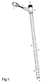
スリーブは、全体的に押し出し法によってポリウレタンなどのプラスチック材料から形成された可撓性の細長い管であり、遠位端部(1a)および近位端部(1b)を備え、かつその長さに沿ってボア(2)が延在している。スリーブは滑らかなまたは実質的に円形の外表面(3)を有し、そこに少なくとも1つの電極、センサーまたはトランスデューサーが配置されている。スリーブを使用して電気刺激を与える場合、図1および図2に示す実施形態のように、一般的に、スリーブの表面上の、患者にそのような刺激を与えるのに好適な個所に、少なくとも一対の電極(4)を位置決めする。電極は、2つの導電性要素(5)に接続されており、これら導電性要素は、細長い管の壁内に横方向に配置され、かつY字接続部(6)に小さく形成されたアパーチャを介して壁から現れ、そこから、絶縁カバー(7)を経て電気コネクタ(8)まで至る。導電性要素は、好ましくは鋼マルチストランドワイヤなどのマルチストランドワイヤから構成されている。電極と導電性要素(5)との間の接続は、スリーブの一セクションを取り除いて、下にある導電性要素を露出させるアパーチャを形成することによって、なされ得る。次いで、ワイヤを戻すように曲げて、導電性接着剤、溶融または溶接を使用して導電性材料のリングを適用し得る。 The sleeve is a flexible elongate tube formed from a plastic material such as polyurethane, generally by an extrusion method, with a distal end (1a) and a proximal end (1b), and to its length. A bore (2) extends along. The sleeve has a smooth or substantially circular outer surface (3) in which at least one electrode, sensor or transducer is arranged. When applying electrical stimulation using a sleeve, as in the embodiment shown in FIGS. 1 and 2, generally at least on the surface of the sleeve, suitable for applying such stimulation to the patient, at least A pair of electrodes (4) are positioned. The electrodes are connected to two conductive elements (5) which are arranged laterally in the wall of the elongated tube and have a small aperture in the Y-connection (6). And emerges from the wall and from there through the insulating cover (7) to the electrical connector (8). The conductive element is preferably composed of a multi-strand wire such as a steel multi-strand wire. The connection between the electrode and the conductive element (5) can be made by removing a section of the sleeve to form an aperture that exposes the underlying conductive element. The wire can then be bent back and a ring of conductive material can be applied using conductive adhesive, melting or welding.
スリーブは、遠位端部(1a)および近位端部(1b)の双方に、ボアと接続したアパーチャを有し、細長いシャフトの挿入、およびシャフトの長さに沿ったスリーブの自由な動きを可能にする。 The sleeve has apertures connected to the bore at both the distal end (1a) and the proximal end (1b) to allow insertion of an elongated shaft and free movement of the sleeve along the length of the shaft. to enable.
図3に示すように、スリーブは、その表面(16)に印刷されたまたは他の方法でマークされた1つ以上のガイドまたは窓を有し、細長いコア構造(17)に対して制御された方法でおよび細長いコア構造の表面に印刷されたマークまたはガイド(18)を参照して位置決めできるようにする。 As shown in FIG. 3, the sleeve has one or more guides or windows printed on its surface (16) or otherwise marked and controlled relative to the elongated core structure (17). Allowing positioning in a manner and with reference to marks or guides (18) printed on the surface of the elongated core structure.
スリーブは、クリップ(19)の使用に適合し、クリップは、スリーブが細長いコア構造に対して正しい位置に調整されたら、スリーブをその構造に可逆的に固定する。クリップは、スリーブの一体部分としてもよいし、または別個の構成要素としてもよい。スリーブをコア構造に可逆的に固定することに加え、クリップはシールを形成して、スリーブとコア構造との間の空間への液体または粒子状物質の侵入を防止する。 The sleeve is compatible with the use of the clip (19), which reversibly secures the sleeve to the structure once the sleeve is adjusted to the correct position relative to the elongated core structure. The clip may be an integral part of the sleeve or may be a separate component. In addition to reversibly securing the sleeve to the core structure, the clip forms a seal to prevent liquid or particulate matter from entering the space between the sleeve and the core structure.
本発明によるカテーテル、特に、図2に示すようなものは、急性嚥下障害を治療する方法において有用であり、そのような方法は、下記で詳細に説明し、かつ以下を含む:
患者の鼻通路の入口にNG管の遠位端部を配置し、耳たぶまで、その後、剣状突起までの管の長さを測定することによって、コアNG管構成要素の挿入距離を測定すること。総距離数は、NG管表面上の印刷ガイドで示される。
スリーブの固定クリップを必要な場合には係合解除して、および透明スリーブの表面にある適切な窓が上述の挿入距離の数字と並ぶ位置まで、スリーブをNG管の表面に沿って動かすこと。
固定クリップを係合することによって、スリーブが独立して動かないようにし、かつカテーテルを、経口的または経鼻的のいずれでもよいが、好ましくは経鼻的に、患者の鼻通路の入口で正しい挿入距離上にある窓がちょうど見えるようになるまで、挿入すること。
NG管構成要素の遠位端部が患者の胃にあることの確認は、標準的な方法によって、すなわちX線または胃内容物を吸引してpHを試験することによって行うこと。
従来の経腸栄養装置に接続することにより、コアNG管を介して栄養を補給すること。
スリーブにある電力供給コネクタに適切な装置を接続することにより治療的電気刺激を与え、かつスリーブにある電極により治療を実施すること。
必要な場合には患者からカテーテル組立体全体を除去せずに、固定クリップを係合解除し、かつスリーブの調整を行うこと。
治療計画の終了後であるが、NG管を除去せずに、固定クリップを係合解除し、かつスリーブを取り除くこと。
必要な場合には患者からスリーブを除去せずに、固定クリップを係合解除してNG管を取り除き、かつスリーブの本体を通して、新しいNG管を、正しい挿入距離数がスリーブの窓と並ぶ位置まで挿入して、固定クリップと係合すること。
A catheter according to the present invention, in particular as shown in FIG. 2, is useful in a method of treating acute dysphagia, such a method is described in detail below and includes:
Measure the insertion distance of the core NG tube component by placing the distal end of the NG tube at the entrance of the patient's nasal passage and measuring the tube length to the earlobe and then to the xiphoid process . The total distance number is indicated by a print guide on the surface of the NG tube.
Disengage the sleeve's securing clip if necessary and move the sleeve along the surface of the NG tube until the appropriate window on the surface of the transparent sleeve is aligned with the above insertion distance number.
Engaging the securing clip prevents the sleeve from moving independently and the catheter may be either oral or nasal, but preferably nasally, at the entrance of the patient's nasal passage Insert until the window over the insertion distance is just visible.
Confirmation that the distal end of the NG tube component is in the patient's stomach should be done by standard methods, i.e. by inhaling X-rays or stomach contents and testing the pH.
Supply nutrition through the core NG tube by connecting to a conventional enteral feeding device.
Providing therapeutic electrical stimulation by connecting an appropriate device to the power supply connector on the sleeve and performing therapy with the electrode on the sleeve;
If necessary, disengage the retaining clip and adjust the sleeve without removing the entire catheter assembly from the patient.
Disengage the retaining clip and remove the sleeve after the treatment plan is complete, but without removing the NG tube.
If necessary, without removing the sleeve from the patient, disengage the securing clip to remove the NG tube, and through the body of the sleeve, place the new NG tube into the position where the correct insertion distance is aligned with the sleeve window. Insert and engage the securing clip.
図2に示す第1の実施形態では、急性嚥下障害を治療する治療的電気刺激と経腸栄養補給の二重機能を有するカテーテルを説明する。 In the first embodiment shown in FIG. 2, a catheter having a dual function of therapeutic electrical stimulation and enteral feeding to treat acute dysphagia will be described.
カテーテルは、あつらえの経鼻胃(NG)栄養管(9)の形態の細長いコア構造を含み、その上に、NG管の長さに沿って自由に動くことができるスリーブが配置される。スリーブは、実質的に透明な可撓性の管であり、ポリウレタン、PVC、ポリアミド、シリコーンまたはこれらの等価材料で作製され、一般に外径が4.7mmであり、内部ルーメンの直径は3.3mmであり、および長さは35〜45cmであり、一対のリング電極と、電極に接続された管の壁に沿って横方向に配置された導電性要素と、ワイヤを電気コネクタまで案内するY型コネクタとを組み込んでいる。スリーブの内側面は、その硬度、形状、仕上げまたはコーティングに関して修正して、その修正によって、スリーブをNG管に配置するとき、またはその上に位置決めしてそれに沿って動かすときの摩擦を最小限にするように助け得る。スリーブは、その表面に印刷されたガイドまたは窓の形態の視覚的な位置表示器を有して、NG管に対するその位置決めを容易にし、かつ固定クリップの使用に適合して、必要なときにはスリーブをNG管に固定する。 The catheter includes an elongate core structure in the form of a custom nasogastric (NG) feeding tube (9), on which is placed a sleeve that is free to move along the length of the NG tube. The sleeve is a substantially transparent flexible tube made of polyurethane, PVC, polyamide, silicone or equivalent materials, generally having an outer diameter of 4.7 mm and an inner lumen diameter of 3.3 mm. And a length of 35-45 cm, a pair of ring electrodes, conductive elements disposed laterally along the wall of the tube connected to the electrodes, and a Y-type that guides the wire to the electrical connector Incorporates a connector. The inner surface of the sleeve is modified with respect to its hardness, shape, finish or coating so that the modification minimizes friction when placing the sleeve on the NG tube or positioning it on and moving along it. You can help as you do. The sleeve has a visual position indicator in the form of a guide or window printed on its surface, facilitating its positioning with respect to the NG tube, and adapted to the use of a securing clip, allowing the sleeve to be Fix to NG tube.
NG管は、直径が好ましくは2.9mm、内部ルーメンの直径は1.9mm、長さが125cmであり、ポリウレタン、シリコーンまたはこれらの等価材料で形成され、その遠位端部(11)には1つ以上のポート(10)を備え、そこを通って、栄養を胃まで通過させることができる。その近位端部(12)には、経腸栄養法セットへの接続部に適合するコネクタ(13)がある。このコネクタは、さらに、必要な場合にNG管から完全に取り外すことができるようになっており、取り外したとき、スリーブを、NG管の近位端部上で摺動させることによってNG管から分離できる。その後、取り外し可能な経腸コネクタを交換して、装置をその後の経腸栄養法のために使用し続けることもできるようにする。NG管の外部表面は、その硬度、形状、仕上げまたはコーティングに関して修正され、その修正によって、NG管の外部表面とスリーブの内部ルーメンの表面との間の摩擦を最小限にするのを助け得る。NG管は、センチメートル単位のガイドを有し、ガイドはその表面に印刷され、遠位端部からの距離を表示する。NG管はまた、内部ルーメン内に位置決めされたガイドワイヤ(14)を組み込んでもよく、ガイドワイヤは、NG管の近位端部から、NG管の遠位端部から1〜3cmの位置まで延び、かつ経腸コネクタに適合するコネクタ(15)に固定されている。 The NG tube preferably has a diameter of 2.9 mm, the inner lumen has a diameter of 1.9 mm and a length of 125 cm, is formed of polyurethane, silicone or an equivalent material thereof, and its distal end (11) has One or more ports (10) are provided through which nutrients can be passed to the stomach. At its proximal end (12) there is a connector (13) that fits into the connection to the enteral nutrition set. The connector is further designed to be completely removable from the NG tube when needed, when detached, the sleeve is separated from the NG tube by sliding over the proximal end of the NG tube. it can. The removable enteral connector is then replaced so that the device can continue to be used for subsequent enteral feeding. The outer surface of the NG tube is modified with respect to its hardness, shape, finish or coating, which may help to minimize friction between the outer surface of the NG tube and the surface of the inner lumen of the sleeve. The NG tube has a centimeter guide, which is printed on its surface to indicate the distance from the distal end. The NG tube may also incorporate a guidewire (14) positioned within the inner lumen, the guidewire extending from the proximal end of the NG tube to a position 1-3 cm from the distal end of the NG tube. And is fixed to a connector (15) adapted to the enteral connector.
以下、図1および図2を参照して装置の使用を説明する。 Hereinafter, the use of the apparatus will be described with reference to FIGS. 1 and 2.
NG管の遠位端部(11)を、患者の外鼻孔に隣接して位置決めする。鼻孔の隣に管の端部の位置を保持する間、管を使用して、患者の耳たぶまでの距離、その後それらの剣状突起までの距離を測定する。鼻孔から耳たぶ、そこから剣状突起までのセンチメートル単位の総距離(NEX)は、NG管の表面に印刷された数字のガイドから得られる。これは、NG管の正しい挿入距離を表し、印された数字が鼻孔の入口で見えるときに、遠位端部が胃の中にあるように十分に管が挿入されたことを保証する。 The distal end (11) of the NG tube is positioned adjacent to the patient's nostril. While holding the position of the end of the tube next to the nostril, the tube is used to measure the distance to the patient's earlobe and then to their xiphoid process. The total distance in centimeters (NEX) from the nostril to the earlobe and from there to the xiphoid process is obtained from a numerical guide printed on the surface of the NG tube. This represents the correct insertion distance of the NG tube and assures that the tube has been inserted sufficiently so that the distal end is in the stomach when the number marked is visible at the nostril entrance.
スリーブは、NG管の遠位端部(11)をスリーブの近位端部(1a)に挿入しかつスリーブの遠位端部(1b)から出現するまでスリーブのボアを通して押し入れることによって、NG管に位置決めする。スリーブ上に印刷された窓が、NG管に印刷されたガイドの挿入距離の数字と位置合わせされるまで、スリーブをNG管の表面に沿って動かす。スリーブを、Y型コネクタのクリップを使用してNG管に固定する。これにより、組み合わされた装置が患者に経鼻的に挿入されて、印刷された窓が鼻孔の入口で見えるとき、NG管の遠位端部が胃の中にあること、およびスリーブにある電極が口腔咽頭部の刺激標的部位内に確実に配置されることの双方を可能にするように、管が十分に挿入されたことを保証する。NG管でのスリーブの相対位置は、患者毎に25cm以上変化し得る。 The sleeve is NG by inserting the distal end (11) of the NG tube into the proximal end (1a) of the sleeve and pushing it through the bore of the sleeve until it emerges from the distal end (1b) of the sleeve. Position on the tube. The sleeve is moved along the surface of the NG tube until the window printed on the sleeve is aligned with the guide insertion distance number printed on the NG tube. The sleeve is secured to the NG tube using a Y-connector clip. This ensures that the distal end of the NG tube is in the stomach and the electrode on the sleeve when the combined device is inserted nasally into the patient and the printed window is visible at the nostril entrance Ensures that the tube has been sufficiently inserted so that it can both be reliably placed within the stimulation target site of the oropharynx. The relative position of the sleeve in the NG tube can vary by more than 25 cm from patient to patient.
装置を、スリーブに印刷された窓が鼻孔への入口で見えるまで、患者に経鼻的に挿入する。ガイドワイヤを取り除き、かつ患者の外部にある装置のセクションを適所に固定する。胃の中でのNG管の遠位端部の位置が正しいことを、胃の吸引液のpH試験によってまたはX線によって、確認する。経腸栄養コネクタ(13)を経腸栄養法セットに接続して、栄養を補給できるようにし得る。 The device is inserted nasally into the patient until the window printed on the sleeve is visible at the entrance to the nostril. Remove the guidewire and secure the section of the device outside the patient in place. The correct position of the distal end of the NG tube in the stomach is confirmed by pH testing of gastric aspirate or by X-ray. An enteral nutrition connector (13) may be connected to the enteral nutrition set to allow replenishment.
治療的電気刺激は、適切な装置をスリーブ上の電力供給コネクタに接続しかつスリーブの電極を介して治療を実施することによって、達成される。電極と標的組織との間に適切な接触が得られない場合、スリーブをNG管に固定するクリップ(19)を係合解除し、スリーブの垂直位置を少し調整してからクリップを再係合してもよい。患者は、好ましくは、10分の間、周波数5Hzおよびパルス幅200μSで一日一度、3日間連続で、最大許容電流レベルの75%で10分間の刺激を受ける。NG管が、直せないほど閉塞される場合、クリップを係合解除し、かつスリーブは適所に保持したままでNG管を完全に取り除いてもよい。その後、新しいNG管を、NEXの数字がスリーブに印刷された窓に並ぶ位置まで挿入し、およびpH試験およびX線を実施して、胃に遠位端部が存在していることを確認し得る。 Therapeutic electrical stimulation is achieved by connecting a suitable device to the power supply connector on the sleeve and performing the therapy via the sleeve electrode. If proper contact is not obtained between the electrode and the target tissue, disengage the clip (19) that secures the sleeve to the NG tube, slightly adjust the vertical position of the sleeve, and then re-engage the clip. May be. Patients are preferably stimulated for 10 minutes at a frequency of 5 Hz and a pulse width of 200 μS once a day for 3 consecutive days for 10 minutes at 75% of the maximum allowable current level. If the NG tube is blocked so that it cannot be repaired, the clip may be disengaged and the NG tube may be completely removed while the sleeve is held in place. A new NG tube is then inserted until the NEX number is aligned with the window printed on the sleeve, and a pH test and X-ray are performed to confirm that the distal end is present in the stomach. obtain.
治療的電気刺激治療計画が完了したら、NG管を取り除かずにスリーブを取り除くことが望ましいかもしれない。これは以下の通り達成される。 Once the therapeutic electrical stimulation treatment plan is complete, it may be desirable to remove the sleeve without removing the NG tube. This is accomplished as follows.
スリーブに印刷された窓を通して見えるNG管の表面上のNEXの数値を確認する。スリーブをNG管に固定するクリップを係合解除し、かつ、スリーブを保持してスリーブが動かないようにし、追加的なNG管を、NEX+20cmに等しい数字がスリーブに印刷された窓に現れるまで、スリーブを通して患者に挿入する。その後クリップを再係合する。 Check the NEX value on the surface of the NG tube visible through the window printed on the sleeve. Disengage the clip that secures the sleeve to the NG tube and hold the sleeve so that the sleeve does not move, until an additional NG tube appears in the window printed on the sleeve, a number equal to NEX + 20 cm. Insert into patient through sleeve. The clip is then reengaged.
次いで、スリーブおよびNGの双方ともを、スリーブの遠位端部が鼻孔から現れかつ元のNEXの数値が鼻孔の入口で見えるまで、ゆっくりと取り除く。これにより、NG管の遠位端部が依然として胃の中にあることを保証する。 Both the sleeve and NG are then slowly removed until the distal end of the sleeve emerges from the nostril and the original NEX value is visible at the nostril entrance. This ensures that the distal end of the NG tube is still in the stomach.
患者が経腸栄養を受けるプロセスにある場合、ポンプのスイッチは切られており、および経腸栄養コネクタは経腸栄養法セットから切り離されている。次いで、経腸栄養コネクタをNG管から取り外し、スリーブをNG管に固定するクリップを係合解除し、およびスリーブを、NG管の近位端部上を摺動させることによってNGから取り除く。NG管の外側部分を適切な消毒用ふきんでしっかりと拭く。 When the patient is in the process of receiving enteral nutrition, the pump is switched off and the enteral nutrition connector is disconnected from the enteral nutrition set. The enteral feeding connector is then removed from the NG tube, the clip securing the sleeve to the NG tube is disengaged, and the sleeve is removed from the NG by sliding over the proximal end of the NG tube. Wipe the outer part of the NG tube with a suitable disinfectant wipe.
経腸コネクタをNG管の近位端部に、その後経腸栄養法セットに再び取り付け、必要に応じて栄養補給を再び開始し得る。 The enteral connector can be reattached to the proximal end of the NG tube and then to the enteral nutrition set, and nutrition resumption can begin again if necessary.
図4aおよび図4bに示す第2の実施形態では、装置は、咽頭電気刺激および測定の二重機能を有する。装置は細長いコア構造(9)を含み、その上には、カテーテルの長さに沿って自由に動くことができるスリーブが配置されている。スリーブは、ポリウレタン、PVC、ポリアミド、シリコーンまたはこれらの等価材料で作製された、実質的に透明の可撓性の管であり、一般に外径4.7mm、内部ルーメンの直径3.3mmおよび長さ35〜45cmであり、一対のリング電極と、電極に接続された管の壁に沿って横方向に配置された導電性要素と、ワイヤを電気コネクタまで案内するY型コネクタとを組み込んでいる。スリーブの内側面は、その硬度、形状、仕上げまたはコーティングに関して修正され、その修正により、スリーブがカテーテルに配置されるまたはカテーテルに位置決めされてそれに沿って動かされるときの摩擦を最小限にするのを助け得る。スリーブは、その表面上に、印刷されたガイドまたは窓を有し、細長いコア構造に対するスリーブの位置決めを容易にする。表面には2つ以上の窓が印刷されて、カテーテルの経鼻または経口のいずれかによる挿入を容易にし得る。スリーブは固定クリップの使用に適合し、必要な場合にスリーブをコア構造に固定する。 In the second embodiment shown in FIGS. 4a and 4b, the device has the dual function of pharyngeal electrical stimulation and measurement. The device includes an elongate core structure (9) on which is placed a sleeve that is free to move along the length of the catheter. The sleeve is a substantially transparent flexible tube made of polyurethane, PVC, polyamide, silicone or an equivalent material, generally 4.7 mm outer diameter, 3.3 mm inner lumen diameter and length. It incorporates a pair of ring electrodes, a conductive element disposed laterally along the wall of the tube connected to the electrodes, and a Y-connector that guides the wire to the electrical connector. The inner surface of the sleeve is modified with respect to its hardness, shape, finish or coating so as to minimize friction when the sleeve is placed on or positioned along the catheter and moved along it. Get help. The sleeve has printed guides or windows on its surface to facilitate positioning of the sleeve relative to the elongated core structure. Two or more windows may be printed on the surface to facilitate insertion of the catheter either nasally or orally. The sleeve is compatible with the use of a securing clip and secures the sleeve to the core structure when necessary.
細長いコア構造(シャフト)はいくつもの形態を取り得る。一実施形態では(図4a)、コア構造は、一般に直径8Frおよび長さ50〜70cmの可撓性の管(20)と、その遠位端部付近の領域には、圧力、特に上部食道括約筋の作用によって加えられる圧力を測定するセンサーまたは他の手段(21)と、管の本体内に、感圧手段に接続されたワイヤ(22)と、その近位端部に、圧力データの処理および表示を行う好適な手段への電気コネクタ(23)とを含む。 The elongated core structure (shaft) can take a number of forms. In one embodiment (FIG. 4a), the core structure is a flexible tube (20), generally 8Fr in diameter and 50-70 cm in length, and in the region near its distal end there is pressure, especially the upper esophageal sphincter. A sensor or other means (21) for measuring the pressure applied by the action of, a wire (22) connected to the pressure sensitive means in the body of the tube, and at its proximal end the pressure data processing and And an electrical connector (23) to suitable means for providing an indication.
図5は、Y型コネクタ(25)の形態のコネクタを有するスリーブ(24)を示し、スリーブは、細長いシャフト(NG管)(26)を把持しかつまたワイヤ(27)を好適な電気コネクタ(28)まで案内するように機能するコレットの形態の可逆的固定手段を組み込んでいる。スリーブ(24)の近位端部は、接着、溶接、オーバーモールディング(over moulding)などによってY型コネクタの近位端部(29)に接合されている。スリーブからの電極ワイヤ(27)が、コネクタのチャネル(30)に飛び出して電気コネクタ部分(28)に至る。コネクタにはEEPROM装置が組み込まれ得る。可逆的固定手段は、ツーピースのコレット装置(31)(32)を含み、NG管を把持または解放するように使用者が調整でき、それゆえ使用者が、NG管部分に対してスリーブ部分を簡単に調整できるようにする第1のピース(31)を含む。Y型コネクタの電気コネクタ部分は、感染予防目的でシール機構、例えばキャップ(図示せず)を組み込んでもよく、キャップを使用して、電気刺激機能が使用されていないときに電気コネクタをシールする。 FIG. 5 shows a sleeve (24) having a connector in the form of a Y-shaped connector (25), which grips an elongated shaft (NG tube) (26) and also attaches a wire (27) to a suitable electrical connector ( 28) incorporates a reversible fixing means in the form of a collet that functions to guide up to 28). The proximal end of the sleeve (24) is joined to the proximal end (29) of the Y connector by gluing, welding, over molding or the like. The electrode wire (27) from the sleeve jumps into the channel (30) of the connector and reaches the electrical connector portion (28). An EEPROM device can be incorporated into the connector. The reversible securing means includes a two-piece collet device (31) (32) that can be adjusted by the user to grip or release the NG tube, so that the user can easily The first piece (31) is included to allow adjustment. The electrical connector portion of the Y-connector may incorporate a sealing mechanism, such as a cap (not shown) for infection prevention purposes, which is used to seal the electrical connector when the electrical stimulation function is not being used.
図6は、スリーブ(24)の近位端部に取り付けられたY型コネクタを示す。Y型コネクタは、ケーシング(33)の形態の可逆的固定手段を組み込んでおり、可逆的固定手段は「波形」(34)を組み込んで、細長いシャフト(NG管)を把持する。NG管に対するスリーブの位置は、NG管を波形チャネル(34)に挿入してケーシングを閉じることによって(図示せず)、使用者によって調整され、かつ使用者によって固定される。 FIG. 6 shows a Y-connector attached to the proximal end of the sleeve (24). The Y-connector incorporates a reversible securing means in the form of a casing (33) that incorporates a “wave” (34) to grip an elongated shaft (NG tube). The position of the sleeve relative to the NG tube is adjusted by the user and fixed by the user by inserting the NG tube into the corrugated channel (34) and closing the casing (not shown).
図7は、スリーブ(24)の近位端部に取り付けられたY型コネクタ(25)を示す。Y型コネクタは、細長いシャフト(NG管)(26)を係合する干渉突起部(35)を有するケーシング(33)の形態の可逆的固定手段を組み込んでおり、干渉突起部は迷路を形成し、それによりNG管を適所にロックする。使用者は、NG管部分に対してスリーブ位置を容易に調整し、かつその後ケーシングの蓋(36)を閉じることによって位置を固定し得る。 FIG. 7 shows a Y-connector (25) attached to the proximal end of the sleeve (24). The Y-connector incorporates reversible fixing means in the form of a casing (33) having an interference projection (35) that engages an elongated shaft (NG tube) (26), the interference projection forming a maze. , Thereby locking the NG tube in place. The user can easily adjust the sleeve position relative to the NG tube portion and then lock the position by closing the casing lid (36).
図8は、スリーブ(24)の近位端部に取り付けられたY型コネクタ(25)を示す。Y型コネクタは、クラムシェルケース(37)の形態の可逆的固定手段を組み込んでおり、これは、細長いシャフト(NG管)(26)に装着された摺動可能な適合グロメット(38)と係合する。グロメットは、変形可能なシリコーンなどの好適な材料で作製し得るので、ポリウレタン製のNG管とグロメットとの間には摩擦が生じる。 FIG. 8 shows the Y connector (25) attached to the proximal end of the sleeve (24). The Y-connector incorporates reversible securing means in the form of a clamshell case (37), which is associated with a slidable matching grommet (38) mounted on an elongated shaft (NG tube) (26). Match. Since the grommet can be made of a suitable material such as deformable silicone, there is friction between the polyurethane NG tube and the grommet.
本発明は、以下のことを含む、急性嚥下障害の治療方法を含む。
・NG管の遠位端部を患者の鼻通路の入口に配置すること、耳たぶまでの、その後剣状突起までの管の長さを測定することによって、コアNG管構成要素の挿入距離を測定すること。総距離数がNG管表面上の印刷されたガイドに示される。
・必要な場合にスリーブ上の固定クリップを係合解除し、かつ透明スリーブの表面上の適切な窓が上述の挿入距離の数字上に並ぶ位置までNG管の表面に沿ってスリーブを動かすこと。
・固定クリップを係合して、スリーブが独立して動かないようにし、かつカテーテルを、経口的または経鼻的のいずれかであるが、好ましくは経鼻的に、正しい挿入距離の窓が患者の鼻通路の入口でちょうど見えるまで、挿入すること。
・NG管構成要素の遠位端部が患者の胃にあることの確認は、標準的な方法によって、すなわちX線、または胃の内容物の吸引およびpH試験によって行うこと。
・従来の経腸栄養装置に接続することによって、コアNG管を介して栄養を補給すること。適切な装置をスリーブの電力供給コネクタに接続すること、およびスリーブの電極を介して治療を実施することによって、治療的電気刺激を与えること。
・必要な場合には、カテーテル組立体全体を患者から取り除くことなく、固定クリップの係合を解除し、かつスリーブを調整すること。
・治療計画が終了した後、NG管を取り除くことなく、固定クリップの係合を解除し、かつスリーブを除去すること。
・必要な場合には、患者からスリーブを取り除くことなく、固定クリップの係合を解除し、かつNG管を除去すること、および正しい挿入距離の数字がスリーブの窓と並ぶ位置まで、スリーブの本体を通して新しいNG管を挿入し、かつ固定クリップを係合すること。
The present invention includes a method of treating acute dysphagia, including:
Measure the insertion distance of the core NG tube component by placing the distal end of the NG tube at the entrance of the patient's nasal passage, measuring the tube length to the earlobe and then to the xiphoid process To do. The total distance number is indicated on the printed guide on the NG tube surface.
• Disengage the securing clip on the sleeve, if necessary, and move the sleeve along the surface of the NG tube to a position where the appropriate window on the surface of the transparent sleeve is aligned with the above insertion distance figures.
Engage the securing clip to prevent the sleeve from moving independently and the catheter, either orally or nasally, but preferably nasally, with a window of the correct insertion distance Insert until it is just visible at the nose passage entrance.
-Confirmation that the distal end of the NG tube component is in the patient's stomach should be done by standard methods, i.e. by X-rays or aspiration of the stomach contents and pH testing.
Replenish nutrition through the core NG tube by connecting to a conventional enteral feeding device. Providing therapeutic electrical stimulation by connecting the appropriate device to the power supply connector of the sleeve and performing the treatment through the electrode of the sleeve.
• If necessary, disengage the securing clip and adjust the sleeve without removing the entire catheter assembly from the patient.
• After the treatment plan is complete, disengage the securing clip and remove the sleeve without removing the NG tube.
-If necessary, disengage the locking clip and remove the NG tube without removing the sleeve from the patient, and the body of the sleeve until the correct insertion distance number is aligned with the sleeve window Insert a new NG tube through and engage the securing clip.
以下、装置のこの実施形態の使用を、図1および図4aを参照して説明する。 In the following, the use of this embodiment of the device will be described with reference to FIGS. 1 and 4a.
コア構造の遠位端部(11)をスリーブの近位端部(1a)に挿入しかつスリーブの遠位端部(1b)から出現するまでスリーブのボアを通して押し入れることによって、スリーブを細長いコア構造に位置決めする。装置を経鼻的または経口的のどちらで挿入するかに依存して、スリーブに印刷された窓が、鼻孔の永久的な入口から上部食道括約筋の中心までの平均距離に対応するコア構造上のマーク、または切歯から上部食道括約筋の中心までの平均距離に対応するマークのいずれかと整列するまで、スリーブをコア構造の表面に沿って動かす。Y型コネクタ上のクリップを使用してスリーブをコア構造に固定する。これにより、組み合わされた装置を経鼻的または経口的に患者に挿入し、かつ印刷された窓が鼻孔の入口または切歯で見えるとき、コア構造の遠位領域に配置された圧力センサーの1つ以上を上部食道括約筋の近くにできるまたはその内部にできると同時に、スリーブ上の電極が口腔咽頭部の刺激標的部位内に確実に配置されるように、管が十分に挿入されていることを保証する。 By inserting the distal end (11) of the core structure into the proximal end (1a) of the sleeve and pushing it through the bore of the sleeve until it emerges from the distal end (1b) of the sleeve, the sleeve is elongated core Position in the structure. Depending on whether the device is inserted nasally or orally, the window printed on the sleeve is on the core structure corresponding to the average distance from the permanent entrance of the nostril to the center of the upper esophageal sphincter The sleeve is moved along the surface of the core structure until it aligns with either the mark or the mark corresponding to the average distance from the incisor to the center of the upper esophageal sphincter. A sleeve on the Y connector is used to secure the sleeve to the core structure. This allows one of the pressure sensors placed in the distal region of the core structure when the combined device is inserted into the patient nasally or orally and the printed window is visible at the nostril entrance or incisor. Ensure that the tube is sufficiently inserted to ensure that the electrode on the sleeve is positioned within the stimulation target site in the oropharynx while one or more can be near or within the upper esophageal sphincter. Guarantee.
コア構造の近位端部上の電気コネクタ(23)は、カテーテルの遠位領域にある圧力センサーからの圧力測定値を分析しかつ表示するための適切な手段に接続される。スリーブとコア構造の組み合わせを、印刷された窓が鼻孔の入口または切歯から約5cmとなるまで、経鼻的または経口的のいずれかで挿入する。そこで、装置を挿入し続けている間、圧力測定値を表示する手段を監視する。圧力の示度値の特徴的な変化は、圧力センサーが上部食道括約筋内にあること、およびコア構造の遠位端部が、上気道ではなく食道内に配置されていることを示す。必要な場合、装置を、さらに、スリーブの表面上に印刷された窓が必要に応じて鼻孔の入口または切歯に配置される時点まで、挿入する。患者の外部にある装置の部分を適所に固定して、不要な動きを防止する。 An electrical connector (23) on the proximal end of the core structure is connected to suitable means for analyzing and displaying pressure measurements from pressure sensors in the distal region of the catheter. The combination of sleeve and core structure is inserted either nasally or orally until the printed window is about 5 cm from the nostril entrance or incisor. Therefore, the means for displaying the pressure measurement is monitored while the device continues to be inserted. A characteristic change in the pressure reading indicates that the pressure sensor is in the upper esophageal sphincter and that the distal end of the core structure is located in the esophagus rather than the upper airway. If necessary, the device is further inserted until a window printed on the surface of the sleeve is placed at the nostril entrance or incisor as required. Secure parts of the device outside the patient in place to prevent unwanted movement.
治療的電気刺激は、適切な装置をスリーブ上の電力供給コネクタに接続し、かつスリーブの電極を介して治療を実施することによって、達成される。電極と標的組織との間に適切な接触が得られない場合、スリーブをコア構造に固定するクリップ(19)を係合解除し、およびスリーブの垂直位置を少し調整してからクリップを再係合してもよい。 Therapeutic electrical stimulation is achieved by connecting a suitable device to the power supply connector on the sleeve and performing the therapy via the sleeve electrodes. If proper contact between the electrode and the target tissue is not achieved, disengage the clip (19) that secures the sleeve to the core structure and adjust the vertical position of the sleeve slightly before re-engaging the clip May be.
治療が完了すると、スリーブとコア構造の組み合わせを患者からゆっくりと取り除く。スリーブをコア構造に固定するクリップを係合解除し、およびスリーブは、摺動させてカテーテルの遠位端部から外すことによって取り除く。治療計画を完了するための次の治療では、毎回、新しい使い捨ての無菌スリーブを使用する。コア構造は、使い捨てでも、または再使用可能でもよい。後者の場合、コア構造を、当業界で公知の標準的な方法によって治療と治療の間に滅菌する。 When the treatment is complete, the sleeve and core structure combination is slowly removed from the patient. The clip that secures the sleeve to the core structure is disengaged and the sleeve is removed by sliding it off the distal end of the catheter. Each subsequent treatment to complete the treatment plan uses a new disposable sterile sleeve. The core structure may be disposable or reusable. In the latter case, the core structure is sterilized between treatments by standard methods known in the art.
図4bに示す実施形態では、細長いコア構造は、一般に直径8Frおよび長さ125cmの可撓性の管(39)と、その遠位端部に近い領域には、胃の内部に位置決めされる、細長い構造の遠位端部と一致するpH、特に低pH値を測定するためのセンサーまたは他の手段(40)と、管の本体内には、pH感知手段に接続するためのワイヤ(41)と、その表面に印刷された、遠位端部からの距離を表示するセンチメートル単位のガイドと、その近位端部には、pHデータを収集、処理および表示する適切な手段へのコネクタ(42)とを含む。 In the embodiment shown in FIG. 4b, the elongate core structure is positioned inside the stomach in a region near the flexible tube (39), generally 8Fr in diameter and 125 cm in length, and its distal end. A sensor or other means (40) for measuring a pH consistent with the distal end of the elongated structure, in particular a low pH value, and a wire (41) for connecting to the pH sensing means in the body of the tube A guide in centimeters that displays the distance from the distal end printed on its surface, and a connector at its proximal end to a suitable means for collecting, processing and displaying pH data ( 42).
以下、装置のこの実施形態の使用を、図1および図4bを参照して説明する。 In the following, the use of this embodiment of the device will be described with reference to FIGS. 1 and 4b.
コア構造の遠位端部を、患者の外鼻孔に隣接して位置決めする。端部の位置を鼻孔の隣に保持する間、コア構造を使用して、患者の耳たぶまでの、そしてそれらの剣状突起までの距離を測定する。鼻孔から耳たぶ、そこから剣状突起までのセンチメートル単位の総距離(NEX)は、コア構造の表面上に印刷された数字のガイドから得られる。これは、印された数字が鼻孔への入口で見えるとき、遠位端部が胃内にあるように管が十分に挿入されたことを保証する、コア構造に対する正しい挿入距離を表す。 The distal end of the core structure is positioned adjacent to the patient's nostril. While holding the end position next to the nostrils, the core structure is used to measure the distance to the patient's earlobe and to their xiphoid process. The total distance in centimeters (NEX) from the nostril to the earlobe and from the xiphoid process is obtained from a numerical guide printed on the surface of the core structure. This represents the correct insertion distance for the core structure, ensuring that the tube is fully inserted so that the distal end is in the stomach when the marked number is visible at the entrance to the nostril.
コア構造の遠位端部をスリーブの近位端部(1a)に挿入しかつスリーブの遠位端部(1b)から出現するまでスリーブのボアを通して押し入れることによって、スリーブをコア構造に位置決めする。スリーブに印刷された適切な窓(カテーテルが経口的または経鼻的のどちらで挿入されるかに依存して)がNEXの数値と位置合わせされるまで、スリーブをコア構造の表面に沿って動かす。Y型コネクタ上のクリップを使用してスリーブをカテーテルに固定する。これは、組み合わされた装置を経鼻的または経口的に患者に挿入して、印刷された窓が鼻孔の入口または切歯で見えるとき、カテーテルの遠位端部が患者の胃の中に確実にあると同時に、スリーブ上の電極が口腔咽頭部の刺激標的部位内に確実に配置されるように、管が十分に挿入されたことを保証する。 The sleeve is positioned in the core structure by inserting the distal end of the core structure into the proximal end (1a) of the sleeve and pushing it through the sleeve bore until it emerges from the distal end (1b) of the sleeve. . Move the sleeve along the surface of the core structure until the appropriate window printed on the sleeve (depending on whether the catheter is inserted orally or nasally) is aligned with the NEX value . A sleeve on the Y-connector is used to secure the sleeve to the catheter. This ensures that the distal end of the catheter is inserted into the patient's stomach when the combined device is inserted into the patient nasally or orally and the printed window is visible at the nostril entrance or incisor. At the same time, it ensures that the tube has been inserted sufficiently to ensure that the electrode on the sleeve is positioned within the stimulation target site of the oropharynx.
印刷された窓が鼻孔の入口または切歯に位置決めされるまで、スリーブとカテーテルの組み合わせを、経鼻的または経口的のいずれかで挿入する。カテーテル(42)の近位端部上のコネクタは、カテーテルの遠位領域にあるpHセンサーからのpH測定値を分析かつ表示する好適な手段に接続される。5.5以下のpH示度値は、コア構造の遠位端部が気道ではなく胃内に配置されていることを示す。患者の外部にある装置の部分を適所に固定して、不要な動きを防止する。 The sleeve and catheter combination is inserted either nasally or orally until the printed window is positioned at the nostril entrance or incisor. The connector on the proximal end of the catheter (42) is connected to a suitable means for analyzing and displaying pH measurements from pH sensors in the distal region of the catheter. A pH reading of 5.5 or less indicates that the distal end of the core structure is located in the stomach rather than the airway. Secure parts of the device outside the patient in place to prevent unwanted movement.
治療的電気刺激は、適切な装置をスリーブ上の電力供給コネクタに接続しかつスリーブの電極を介して治療を実施することにより、達成される。電極と標的組織との間に適切な接触が得られない場合、スリーブをコア構造に固定するクリップ(43)を係合解除し、およびスリーブの垂直位置を少し調整してから、クリップを再係合してもよい。 Therapeutic electrical stimulation is achieved by connecting a suitable device to the power supply connector on the sleeve and performing the therapy via the sleeve electrode. If proper contact is not obtained between the electrode and the target tissue, disengage the clip (43) that secures the sleeve to the core structure and slightly adjust the vertical position of the sleeve before re-engaging the clip. May be combined.
治療が完了したら、スリーブとコア構造の組み合わせを患者からゆっくりと取り除く。スリーブをカテーテルに固定するクリップを係合解除し、およびスリーブを摺動させてコア構造の遠位端部から外すことによって、スリーブを取り除く。治療計画を完了するための次の治療は、毎回、新しい使い捨ての無菌スリーブを用いる。コア構造は使い捨てでも、または再使用可能でもよい。後者の場合、コア構造を、当業界で公知の標準的な方法によって治療と治療の間に滅菌する。 When treatment is complete, the sleeve and core structure combination is slowly removed from the patient. The sleeve is removed by disengaging the clip that secures the sleeve to the catheter and sliding the sleeve out of the distal end of the core structure. Each subsequent treatment to complete the treatment plan uses a new disposable sterile sleeve. The core structure may be disposable or reusable. In the latter case, the core structure is sterilized between treatments by standard methods known in the art.
Claims (22)
i)栄養管と;
ii)1つ以上の電極を組み込んだスリーブであって、前記スリーブの位置が調整可能であるように、前記カテーテルを体に挿入する前に前記栄養管に沿って可動であるスリーブと;
iii)前記スリーブが適所になると前記スリーブを前記栄養管に対して固定する手段と;を具え、
前記栄養管とスリーブは、前記栄養管とスリーブを体にともに挿入して、前記スリーブを体から取り出さずに前記栄養管を選択的に体から取り外すことが可能であり、および/または前記栄養管を体から取り外さずに前記スリーブを選択的に体から取り外すことが可能であるように構成されている、ことを特徴とするカテーテル。 In a pharyngeal stimulation catheter that provides electrical stimulation to the body to help recover from dysphagia:
i) a feeding tube ;
ii) a sleeve incorporating one or more electrodes, wherein the sleeve is movable along the feeding tube before the catheter is inserted into the body so that the position of the sleeve is adjustable;
iii) means for securing the sleeve to the feeding tube when the sleeve is in place ;
The feeding tube and sleeve can be inserted into the body together and the feeding tube can be selectively removed from the body without removing the sleeve from the body and / or the feeding tube A catheter configured to allow the sleeve to be selectively removed from the body without removing it from the body.
Applications Claiming Priority (3)
| Application Number | Priority Date | Filing Date | Title |
|---|---|---|---|
| GB1105622.3 | 2011-04-01 | ||
| GB201105622A GB201105622D0 (en) | 2011-04-01 | 2011-04-01 | Multi functional catheter |
| PCT/GB2012/000288 WO2012131303A1 (en) | 2011-04-01 | 2012-03-30 | Multi-functional catheter |
Publications (3)
| Publication Number | Publication Date |
|---|---|
| JP2014513617A JP2014513617A (en) | 2014-06-05 |
| JP2014513617A5 JP2014513617A5 (en) | 2015-04-23 |
| JP6030629B2 true JP6030629B2 (en) | 2016-11-24 |
Family
ID=44071872
Family Applications (1)
| Application Number | Title | Priority Date | Filing Date |
|---|---|---|---|
| JP2014501705A Active JP6030629B2 (en) | 2011-04-01 | 2012-03-30 | Multi-function catheter |
Country Status (19)
| Country | Link |
|---|---|
| US (3) | US20140288384A1 (en) |
| EP (1) | EP2693968B1 (en) |
| JP (1) | JP6030629B2 (en) |
| KR (1) | KR102052213B1 (en) |
| CN (1) | CN103533906B (en) |
| AU (1) | AU2012235988B2 (en) |
| BR (1) | BR112013025246A2 (en) |
| CA (1) | CA2831891C (en) |
| DK (1) | DK2693968T3 (en) |
| EA (1) | EA024547B1 (en) |
| ES (1) | ES2577007T3 (en) |
| GB (1) | GB201105622D0 (en) |
| IL (1) | IL228550B (en) |
| MX (1) | MX2013011103A (en) |
| PL (1) | PL2693968T3 (en) |
| PT (1) | PT2693968T (en) |
| SG (1) | SG193959A1 (en) |
| WO (1) | WO2012131303A1 (en) |
| ZA (1) | ZA201308102B (en) |
Families Citing this family (17)
| Publication number | Priority date | Publication date | Assignee | Title |
|---|---|---|---|---|
| CN103796713B (en) | 2011-06-27 | 2016-05-04 | 电子运动医疗有限公司 | Oesophageal irritation device and method |
| US9999767B2 (en) | 2011-06-27 | 2018-06-19 | E-Motion Medical, Ltd. | Esophageal stimulation system |
| EP2934667A1 (en) * | 2012-12-24 | 2015-10-28 | E-Motion Medical, Ltd. | Gi tract stimulation devices and methods |
| DE102014107087A1 (en) * | 2014-05-20 | 2015-11-26 | Bowa-Electronic Gmbh & Co. Kg | Sondenapplikator |
| GB2532044A (en) * | 2014-11-06 | 2016-05-11 | Phagenesis Ltd | Catheter for recovery of dysphagia |
| GB2540998A (en) * | 2015-08-04 | 2017-02-08 | Phagenesis Ltd | Catheter |
| GB201513989D0 (en) | 2015-08-07 | 2015-09-23 | Phagenesis Ltd | Method of diagnosis of dysphagia |
| GB2544780A (en) * | 2015-11-26 | 2017-05-31 | Phagenesis Ltd | Devices and methods for treatment of ventilator associated dysphagia |
| US20180195920A1 (en) * | 2016-05-12 | 2018-07-12 | Solid Year Co., Ltd. | Pressure sensing device, pressure sensing system and pressure switch using same |
| GB201609425D0 (en) * | 2016-05-27 | 2016-07-13 | Phagenesis Ltd | Device for treatment of dysphagia |
| CN110248600A (en) * | 2016-12-06 | 2019-09-17 | 艾特医疗有限公司 | For sensing the system and method for lung liquid |
| US20200163713A1 (en) * | 2017-05-08 | 2020-05-28 | Crossfire Medical Llc | Catheter systems and methods for ablating varicose veins |
| KR20190013207A (en) * | 2017-08-01 | 2019-02-11 | 김덕수 | Surgical guide wire |
| US10940308B2 (en) | 2017-08-04 | 2021-03-09 | Lungpacer Medical Inc. | Systems and methods for trans-esophageal sympathetic ganglion recruitment |
| CN109549629B (en) * | 2018-11-29 | 2021-09-28 | 西安交通大学第二附属医院 | Gastrointestinal motility detection device |
| CN111150933B (en) * | 2019-09-02 | 2022-08-09 | 杭州神络医疗科技有限公司 | Catheter electrode and in vivo implanted nerve stimulation device |
| US20220161029A1 (en) * | 2020-11-20 | 2022-05-26 | Phagenesis Limited | Devices, systems, and methods for treating disease using electrical stimulation |
Family Cites Families (28)
| Publication number | Priority date | Publication date | Assignee | Title |
|---|---|---|---|---|
| US4381011A (en) * | 1981-05-04 | 1983-04-26 | Somers 3Rd Lewis S | Enteral feeding apparatus and method |
| US4531937A (en) * | 1983-01-24 | 1985-07-30 | Pacesetter Systems, Inc. | Introducer catheter apparatus and method of use |
| US4960412A (en) * | 1988-04-15 | 1990-10-02 | Universal Medical Instrument Corp. | Catheter introducing system |
| DE3836349A1 (en) | 1988-10-25 | 1990-05-03 | Forschungsgesellschaft Fuer Bi | CATHETER FOR MEASURING MOTILITY AND PERISTALTICS IN HOSE-SHAPED ORGANS WHICH CONTAIN THEIR CONTENT BY SIMULTANEOUS MULTIPLE IMPEDANCE MEASUREMENT |
| US5125904B1 (en) * | 1991-07-09 | 1996-11-19 | Hl Medical Inventions Inc | Splittable hemostatic valve sheath and the method for using the same |
| JPH11503041A (en) * | 1995-03-31 | 1999-03-23 | ボストン・サイエンティフィック・コーポレーション | Biopsy sampler |
| JP3790286B2 (en) * | 1995-08-03 | 2006-06-28 | 株式会社町田製作所 | Endoscopic high-frequency treatment instrument |
| US6592581B2 (en) * | 1998-05-05 | 2003-07-15 | Cardiac Pacemakers, Inc. | Preformed steerable catheter with movable outer sleeve and method for use |
| US6259938B1 (en) * | 1998-05-15 | 2001-07-10 | Respironics, Inc. | Monitoring catheter and method of using same |
| US6544226B1 (en) | 2000-03-13 | 2003-04-08 | Curon Medical, Inc. | Operative devices that can be removably fitted on catheter bodies to treat tissue regions in the body |
| US6733500B2 (en) * | 2000-03-31 | 2004-05-11 | Medtronic, Inc. | Method and system for delivering a medical electrical lead within a venous system |
| US6270226B1 (en) | 2000-05-16 | 2001-08-07 | William G. Taylor | Multi-view imaging device |
| US6771996B2 (en) * | 2001-05-24 | 2004-08-03 | Cardiac Pacemakers, Inc. | Ablation and high-resolution mapping catheter system for pulmonary vein foci elimination |
| DE60221289T2 (en) * | 2001-11-29 | 2008-04-10 | Cook Inc., Bloomington | FEEDING SYSTEM FOR MEDICAL DEVICES |
| US7435248B2 (en) | 2003-09-26 | 2008-10-14 | Boston Scientific Scimed, Inc. | Medical probes for creating and diagnosing circumferential lesions within or around the ostium of a vessel |
| JP2007519498A (en) | 2004-01-30 | 2007-07-19 | エヌエムティー メディカル, インコーポレイティッド | Devices, systems, and methods for closure of cardiac openings |
| US7632266B2 (en) | 2004-02-17 | 2009-12-15 | Boston Scientific Scimed, Inc. | Endoscopic devices and related methods of use |
| US8608727B2 (en) * | 2004-03-01 | 2013-12-17 | Smiths Medical Asd, Inc. | Delivery system and method |
| US7594910B2 (en) * | 2004-03-18 | 2009-09-29 | C. R. Bard, Inc. | Catheter connector |
| GB0419238D0 (en) | 2004-08-28 | 2004-09-29 | Univ Manchester | Dysphagia recovery |
| US8360968B2 (en) * | 2004-12-01 | 2013-01-29 | Vision—Sciences Inc. | Endoscopic sheath with illumination |
| US7976518B2 (en) * | 2005-01-13 | 2011-07-12 | Corpak Medsystems, Inc. | Tubing assembly and signal generator placement control device and method for use with catheter guidance systems |
| CN2873126Y (en) * | 2006-02-28 | 2007-02-28 | 上海众为医疗设备有限公司 | Composite type electrode needle |
| GB2437057A (en) | 2006-04-12 | 2007-10-17 | Sean Julian Thomas | Tube having positioning means for delivering fluid to a predetermining location |
| US9295395B2 (en) * | 2007-03-02 | 2016-03-29 | Art Healthcare Ltd. | Interactive NGT system |
| US8366615B2 (en) * | 2009-01-05 | 2013-02-05 | Texas Heart Institute | Introducer sheath with electrodes |
| RU2548138C2 (en) * | 2008-08-28 | 2015-04-10 | Конинклейке Филипс Электроникс Н.В. | Application, device and method of obtaining physiological signals by feeding tube |
| JP2010213946A (en) | 2009-03-18 | 2010-09-30 | Fujifilm Corp | High frequency treatment instrument |
-
2011
- 2011-04-01 GB GB201105622A patent/GB201105622D0/en not_active Ceased
-
2012
- 2012-03-30 MX MX2013011103A patent/MX2013011103A/en active IP Right Grant
- 2012-03-30 SG SG2013072335A patent/SG193959A1/en unknown
- 2012-03-30 ES ES12716504.1T patent/ES2577007T3/en active Active
- 2012-03-30 US US14/009,195 patent/US20140288384A1/en not_active Abandoned
- 2012-03-30 PL PL12716504.1T patent/PL2693968T3/en unknown
- 2012-03-30 AU AU2012235988A patent/AU2012235988B2/en not_active Ceased
- 2012-03-30 EA EA201391328A patent/EA024547B1/en not_active IP Right Cessation
- 2012-03-30 BR BR112013025246A patent/BR112013025246A2/en active Search and Examination
- 2012-03-30 KR KR1020137028811A patent/KR102052213B1/en active IP Right Grant
- 2012-03-30 EP EP12716504.1A patent/EP2693968B1/en active Active
- 2012-03-30 DK DK12716504.1T patent/DK2693968T3/en active
- 2012-03-30 PT PT127165041T patent/PT2693968T/en unknown
- 2012-03-30 WO PCT/GB2012/000288 patent/WO2012131303A1/en active Application Filing
- 2012-03-30 CN CN201280021247.0A patent/CN103533906B/en active Active
- 2012-03-30 CA CA2831891A patent/CA2831891C/en active Active
- 2012-03-30 JP JP2014501705A patent/JP6030629B2/en active Active
-
2013
- 2013-09-29 IL IL228550A patent/IL228550B/en active IP Right Grant
- 2013-10-30 ZA ZA2013/08102A patent/ZA201308102B/en unknown
-
2015
- 2015-12-02 US US14/956,599 patent/US20160081624A1/en not_active Abandoned
-
2017
- 2017-03-17 US US15/462,219 patent/US10413358B2/en active Active
Also Published As
| Publication number | Publication date |
|---|---|
| PL2693968T3 (en) | 2016-10-31 |
| SG193959A1 (en) | 2013-11-29 |
| NZ615841A (en) | 2015-01-30 |
| DK2693968T3 (en) | 2016-06-27 |
| ZA201308102B (en) | 2015-07-29 |
| US20170189110A1 (en) | 2017-07-06 |
| BR112013025246A2 (en) | 2016-12-20 |
| ES2577007T3 (en) | 2016-07-12 |
| EP2693968B1 (en) | 2016-03-30 |
| KR102052213B1 (en) | 2020-01-08 |
| WO2012131303A1 (en) | 2012-10-04 |
| AU2012235988B2 (en) | 2015-10-29 |
| CN103533906A (en) | 2014-01-22 |
| MX2013011103A (en) | 2014-03-31 |
| US10413358B2 (en) | 2019-09-17 |
| US20140288384A1 (en) | 2014-09-25 |
| PT2693968T (en) | 2016-07-07 |
| EA024547B1 (en) | 2016-09-30 |
| KR20140025424A (en) | 2014-03-04 |
| IL228550B (en) | 2018-08-30 |
| US20160081624A1 (en) | 2016-03-24 |
| CA2831891A1 (en) | 2012-10-04 |
| EA201391328A1 (en) | 2014-03-31 |
| IL228550A0 (en) | 2013-12-31 |
| CA2831891C (en) | 2020-09-01 |
| AU2012235988A1 (en) | 2013-10-17 |
| JP2014513617A (en) | 2014-06-05 |
| CN103533906B (en) | 2016-08-31 |
| EP2693968A1 (en) | 2014-02-12 |
| GB201105622D0 (en) | 2011-05-18 |
Similar Documents
| Publication | Publication Date | Title |
|---|---|---|
| JP6030629B2 (en) | Multi-function catheter | |
| US7740620B2 (en) | Insertion system and methods for nasogastric tubes including feeding tubes | |
| US7695459B2 (en) | Nasogastric tube insertion system and method | |
| US20080249507A1 (en) | Emergency Electrode on Medical Tube | |
| JP2013521040A (en) | Multifunctional feeding tube | |
| WO2006060458A1 (en) | Emergency electrode on medical tube | |
| US20210077808A1 (en) | Catheter for recovery of dysphagia | |
| NZ615841B2 (en) | A pharyngeal stimulation catheter | |
| EP4247479A1 (en) | Devices, systems, and methods for treating disease using electrical stimulation |
Legal Events
| Date | Code | Title | Description |
|---|---|---|---|
| A521 | Request for written amendment filed |
Free format text: JAPANESE INTERMEDIATE CODE: A523 Effective date: 20150306 |
|
| A621 | Written request for application examination |
Free format text: JAPANESE INTERMEDIATE CODE: A621 Effective date: 20150306 |
|
| A131 | Notification of reasons for refusal |
Free format text: JAPANESE INTERMEDIATE CODE: A131 Effective date: 20160202 |
|
| A601 | Written request for extension of time |
Free format text: JAPANESE INTERMEDIATE CODE: A601 Effective date: 20160426 |
|
| A521 | Request for written amendment filed |
Free format text: JAPANESE INTERMEDIATE CODE: A523 Effective date: 20160701 |
|
| TRDD | Decision of grant or rejection written | ||
| A01 | Written decision to grant a patent or to grant a registration (utility model) |
Free format text: JAPANESE INTERMEDIATE CODE: A01 Effective date: 20161018 |
|
| A61 | First payment of annual fees (during grant procedure) |
Free format text: JAPANESE INTERMEDIATE CODE: A61 Effective date: 20161020 |
|
| R150 | Certificate of patent or registration of utility model |
Ref document number: 6030629 Country of ref document: JP Free format text: JAPANESE INTERMEDIATE CODE: R150 |
|
| R250 | Receipt of annual fees |
Free format text: JAPANESE INTERMEDIATE CODE: R250 |
|
| R250 | Receipt of annual fees |
Free format text: JAPANESE INTERMEDIATE CODE: R250 |
|
| R250 | Receipt of annual fees |
Free format text: JAPANESE INTERMEDIATE CODE: R250 |
|
| R250 | Receipt of annual fees |
Free format text: JAPANESE INTERMEDIATE CODE: R250 |