JP6029209B2 - Cylinder lock protector - Google Patents
Cylinder lock protector Download PDFInfo
- Publication number
- JP6029209B2 JP6029209B2 JP2013099029A JP2013099029A JP6029209B2 JP 6029209 B2 JP6029209 B2 JP 6029209B2 JP 2013099029 A JP2013099029 A JP 2013099029A JP 2013099029 A JP2013099029 A JP 2013099029A JP 6029209 B2 JP6029209 B2 JP 6029209B2
- Authority
- JP
- Japan
- Prior art keywords
- cylinder lock
- cover
- shutter plate
- case member
- cover member
- Prior art date
- Legal status (The legal status is an assumption and is not a legal conclusion. Google has not performed a legal analysis and makes no representation as to the accuracy of the status listed.)
- Active
Links
Images


Landscapes
- Lock And Its Accessories (AREA)
Description
本発明は、シリンダ錠の一端部を覆うように固定配置されるケース部材ならびに該ケース部材を前記シリンダ錠とは反対側から覆うカバー部材から成るケーシングに、マグネット錠が配設されるとともに、前記マグネット錠の解錠時に前記シリンダ錠のキー孔を閉じる閉じ位置ならびに前記キー孔を開放する開き位置間で作動するシャッター板が収容されるシリンダ錠の保護装置に関する。 According to the present invention, a magnet lock is disposed in a casing formed of a case member fixedly arranged so as to cover one end portion of the cylinder lock and a cover member that covers the case member from the side opposite to the cylinder lock. The present invention relates to a protection device for a cylinder lock in which a shutter plate that operates between a closed position for closing a key hole of the cylinder lock and an open position for opening the key hole when the magnet lock is unlocked.
マグネット錠の解錠時に、シリンダ錠のキー孔を開閉し得るシャッター板を開閉作動可能とした保護装置が、たとえば特許文献1で知られている。 For example, Patent Document 1 discloses a protection device that can open and close a shutter plate that can open and close a key hole of a cylinder lock when unlocking a magnetic lock.
ところが、上記特許文献1で開示されたものでは、シャッター板を収容するケーシングのカバー部材が、防盗性を確保するために亜鉛合金等の金属によって形成されており、重量増加を招き、シリンダ錠が設けられる車両の大重量化に繋がってしまう。 However, in the one disclosed in Patent Document 1, the cover member of the casing that accommodates the shutter plate is formed of a metal such as zinc alloy in order to ensure the anti-theft property, which causes an increase in weight, and the cylinder lock This leads to an increase in the weight of the vehicle provided.
本発明は、防盗性を確保しつつ軽量化を可能としたシリンダ錠の保護装置を提供することを目的とする。 SUMMARY OF THE INVENTION An object of the present invention is to provide a cylinder lock protection device that can be reduced in weight while ensuring theft prevention.
上記目的を達成するために、本発明は、シリンダ錠の一端部を覆うように固定配置されるケース部材ならびに該ケース部材を前記シリンダ錠とは反対側から覆うカバー部材から成るケーシングに、マグネット錠が配設されるとともに、前記マグネット錠の解錠時に前記シリンダ錠のキー孔を閉じる閉じ位置ならびに前記キー孔を開放する開き位置間で作動するシャッター板が収容されるシリンダ錠の保護装置において、前記カバー部材が合成樹脂から成り、前記カバー部材が合成樹脂から成り、前記カバー部材および前記シャッター板間に介在するようにして平板状に形成されるとともに前記シャッター板に摺接する突条が一体に形成される金属製のプロテクタが、前記シャッター板を覆うようにして前記ケース部材に固定されることを第1の特徴とする。 In order to achieve the above-described object, the present invention provides a casing including a case member fixedly arranged so as to cover one end of a cylinder lock, and a cover member covering the case member from the opposite side to the cylinder lock. In the cylinder lock protection device in which a shutter plate that operates between a closed position that closes the key hole of the cylinder lock and an open position that opens the key hole when the magnetic lock is unlocked is accommodated. The cover member is made of a synthetic resin, the cover member is made of a synthetic resin, and is formed in a flat plate shape so as to be interposed between the cover member and the shutter plate, and a protrusion that slides on the shutter plate is integrally formed. metal protector to be formed, to be fixed to the casing member so as to cover the shutter plate first And features.
また本発明は、シリンダ錠の一端部を覆うように固定配置されるケース部材ならびに該ケース部材を前記シリンダ錠とは反対側から覆うカバー部材から成るケーシングに、マグネット錠が配設されるとともに、前記マグネット錠の解錠時に前記シリンダ錠のキー孔を閉じる閉じ位置ならびに前記キー孔を開放する開き位置間で作動するシャッター板が収容されるシリンダ錠の保護装置において、前記カバー部材が合成樹脂から成るとともに、複数箇所で前記ケース部材に弾発係合され、前記カバー部材および前記シャッター板間に介在するようにして平板状に形成される金属製のプロテクタが、前記シャッター板を覆うようにして前記ケース部材に固定され、前記シリンダ錠から離隔した位置に配置される開閉体のロック状態を解除することを可能とした開閉体遠隔操作部が、前記複数箇所の弾発係合部の少なくとも1つを覆うように前記カバー部材の外面に当接して、前記ケース部材に取付けられることを第2の特徴とする。 In the present invention , a magnet lock is disposed in a casing formed of a case member fixedly arranged so as to cover one end of the cylinder lock and a cover member that covers the case member from the opposite side of the cylinder lock, In the cylinder lock protection device in which a shutter plate that operates between a closed position that closes the key hole of the cylinder lock and an open position that opens the key hole when the magnetic lock is unlocked is stored, the cover member is made of synthetic resin. And a metal protector which is elastically engaged with the case member at a plurality of locations and is formed in a flat plate shape so as to be interposed between the cover member and the shutter plate so as to cover the shutter plate. Releasing the lock state of the opening / closing body fixed to the case member and disposed at a position separated from the cylinder lock; Possible and the closing member remote operation unit, the contact with the outer surface of at least one so as to cover the cover member of resilient engagement of the plurality of positions, and the second, characterized in that attached to the case member To do.
本発明は、第2の特徴の構成に加えて、前記カバー部材と、前記開閉体遠隔操作部との間に、前記カバー部材および前記開閉体遠隔操作部の外面の意匠面を合わせるための位置決め部が設けられることを第3の特徴とする。 According to the present invention, in addition to the configuration of the second feature, positioning for aligning the design surface of the cover member and the outer surface of the opening / closing body remote control unit between the cover member and the opening / closing body remote control unit The third feature is that the portion is provided.
本発明は、第1または第2の特徴の構成に加えて、前記プロテクタが前記ケース部材にかしめ固定されていることを第4の特徴とする。 The present invention, in addition to the configuration of the first or second feature, a fourth feature in that the protector is fixed by caulking to the case member.
さらに本発明は、第2の特徴の構成に加えて、前記プロテクタに、前記シャッター板に摺接する突条が一体に形成されることを第5の特徴とする。 Furthermore, the present invention is characterized in that, in addition to the configuration of the second feature, a protrusion that slides on the shutter plate is integrally formed on the protector .
本発明の第1の特徴によれば、シャッター板を収容するケーシングのうちカバー部材を合成樹脂製として軽量化を図るとともに、平板状である金属製のプロテクタで防盗性を高めることができ、プロテクタに設けられる突条がシャッター板に摺接するので、シャッター板の摺動抵抗を小さくして摺動性を高めることができる。 According to a first aspect of the present invention, while achieving the weight of the cover member of the casing housing the shutter plate as synthetic resin, it is possible to improve the antitheft property with a metal protector are tabular, the protector Since the protrusion provided on the shutter slides on the shutter plate, the sliding resistance of the shutter plate can be reduced to improve the sliding property .
また本発明の第2の特徴によれば、開閉体遠隔操作部が、カバー部材およびケース部材の複数の弾発係合部の少なくとも1つを覆うようにカバー部材に当接してケース部材に取付けられるので、少なくとも1つの弾発係合部の係合状態の解除を開閉体遠隔操作部で阻止することができ、ケース部材からのカバー部材の外れ防止構造を簡単に構成することができる。 According to the second aspect of the present invention, the opening / closing body remote control unit is attached to the case member by contacting the cover member so as to cover at least one of the cover member and the plurality of elastic engagement portions of the case member. Therefore, release of the engagement state of the at least one elastic engagement portion can be prevented by the opening / closing body remote control portion, and a structure for preventing the cover member from coming off from the case member can be easily configured.
本発明の第3の特徴によれば、カバー部材および開閉体遠隔操作部の外面の意匠面を合わせるための位置決め部が、カバー部材および開閉体遠隔操作部間に設けられるので、意匠面のずれを防止することができる。 According to the third feature of the present invention, the positioning portion for aligning the outer design surface of the cover member and the opening / closing body remote operation portion is provided between the cover member and the opening / closing body remote operation portion. Can be prevented.
本発明の第4の特徴によれば、プロテクタがケース部材にかしめ固定されるので、カバー部材がケース部材から外れてもプロテクタをケース部材から外すことは困難であり、プロテクタのケース部材への確実な固定が可能となる。 According to the fourth feature of the present invention, since the protector is caulked and fixed to the case member, it is difficult to remove the protector from the case member even if the cover member is detached from the case member. Can be fixed.
さらに本発明の第5の特徴によれば、プロテクタに設けられる突条がシャッター板に摺接するので、シャッター板の摺動抵抗を小さくして摺動性を高めることができる。 Furthermore, according to the fifth feature of the present invention, since the protrusion provided on the protector is in sliding contact with the shutter plate, the sliding resistance of the shutter plate can be reduced and the slidability can be improved.
以下、本発明の実施の形態について、添付の図面を参照しながら説明する。 Hereinafter, embodiments of the present invention will be described with reference to the accompanying drawings.
本発明の第1の実施の形態について図1〜図8を参照しながら説明すると、先ず図1において、車両たとえば自動二輪車用における車体カバー15には集中解錠操作装置16が配設される。
A first embodiment of the present invention will be described with reference to FIGS. 1 to 8. First, in FIG. 1, a central
図2および図3を併せて参照して、前記集中解錠操作装置16は、メインスイッチ17と、該メインスイッチ17の一側に配置される開閉体遠隔操作部18とを備える。
2 and 3 together, the centralized
前記メインスイッチ17は、メカニカルキーで操作されるシリンダ錠19と、該シリンダ錠19の操作によってスイッチング態様を切換えるようにして前記シリンダ錠19に連設されるイグニッションスイッチ20とを備え、前記シリンダ錠19は、前記イグニッションスイッチ20のスイッチング態様の切換えだけでなく、ステアリングのロック状態およびアンロック状態を切換え可能である。
The
前記シリンダ錠19は、車体フレームに固定されるシリンダボディ21と、キー孔22を有してシリンダボディ21に回動可能に収容されるインナシリンダ23と、前記キー孔22へのメカニカルキーの挿入に応じて前記シリンダボディ21との係合を解除するようにして前記インナシリンダ23に配設される複数のタンブラー24とを備える。
The
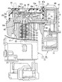
前記シリンダボディ21の前記イグニッションスイッチ20とは反対側の一端部には、保護装置25が連設される。この保護装置25は、前記シリンダボディ21の一端部を覆うケーシング26と、該ケーシング26に配設されるマグネット錠27と、前記ケーシング26内に収容されるシャッター板28とを備える。
A
図4を併せて参照して、前記ケーシング26は、前記シリンダボディ21にボルトで締結されることで固定配置される非磁性材料製のケース部材29と、該ケース部材29を前記シリンダボディ21と反対側から覆うようにして該ケース部材29に取付けられる合成樹脂製のカバー部材30とから成る。
Referring also to FIG. 4, the
前記カバー部材30は、前記ケース部材29の外周の一部を外側方から覆う側壁部30aを有するように形成されており、該側壁部30aに形成される複数の係合孔32に、前記ケース部材29の複数箇所に設けられる係合突起33を係合させて成る複数の弾発係合部34で、前記カバー部材30が前記ケース部材29に弾発係合される。
The
前記ケース部材29および前記カバー部材30には、前記シリンダ錠19の前記キー孔22にメカニカルキーを挿入することを可能とした挿入孔35,36が設けられる。
The
図5〜図7を併せて参照して、ケーシング26内には、前記挿入孔35,36間を遮断して前記キー孔22を閉じる閉じ位置(図5および図6の位置)と、前記挿入孔35,36および前記キー孔22を開放して前記挿入孔35,36から前記キー孔22への前記メカニカルキーの挿入を可能とした開き位置(図7の位置)と間でのスライド作動を可能としたシャッター板28が収納される。
Referring also to FIGS. 5 to 7, in the
このシャッター板28のスライド作動は、ケーシング26に配設されるマグネット錠27が備える嵌合凹部39に、マグネットキーを嵌合することで許容されるものであり、マグネット錠27は、前記ケーシング26の前記ケース部材29で回動可能に支承されるロータ40を備え、変則多角形状の前記嵌合凹部39が前記ロータ40に設けられる。
The sliding operation of the
図4に注目して、前記ケーシング26のケース部材29には、前記カバー部材30側に突出した横断面円形の支持突部29aが一体に突設されており、該支持突部29aに対応する部分でカバー部材30には円形の開口部41が設けられる。前記ロータ40は、非磁性材料により略円筒状に形成されており、前記支持突部29aで回動可能に支承され、支持突部29aの基部およびロータ40間にはOリング42が介装され、前記ロータ40の外端は前記開口部41に臨むように配置される。
4, the
前記支持突部29aの先端部には、マグネットから成る複数個たとえば3個のピン43が前記ロータ40に係合する位置ならびにその係合を解除する位置間での移動を可能として摺動可能に嵌合されており、各ピン43は、個別に対応したばね44によって前記ロータ40に係合する側に弾発付勢される。
The tip of the
このようなマグネット錠27では、前記ロータ40の嵌合凹部39に正規のマグネットキーを嵌合することで前記ばね44の弾発付勢力に抗して前記ピン43を前記ロータ40との係合を解除する側に移動させることができ、それによって前記ロータ40の回動が許容されることになる。
In such a
前記ケーシング26内に収納された前記シャッター板28は、前記閉じ位置および前記開き位置間で直線的に移動するものであり、前記ロータ40の回動および前記シャッター板28の直線的な移動が連動するように前記ロータ40が前記シャッター板28に連結される。前記ロータ40および前記シャッター板28を連結するために、この実施の形態では、前記シャッター板28の一端側に延びる連結アーム40aが前記ロータ40の外周に一体に設けられ、該連結アーム40aの先端部に設けられた連結軸45が、前記シャッター板28の下端部に設けられる連結孔46に挿通される。
The
前記ケーシング26内には、前記シャッター板28を覆う金属製のプロテクタ47が収容されるものであり、このプロテクタ47は、前記カバー部材30および前記シャッター板28間に介在するようにして平板状に形成される。また前記シャッター板28の上下移動方向と略平行に延びる突壁部47aが前記プロテクタ47の一側部に直角にかつ一体に連設され、前記プロテクタ47の複数箇所たとえば3箇所には円形のかしめ孔48,49,50が形成される。一方、前記カバー部材30には前記突壁部46aを収容させる収容凹部51が形成され、前記ケース部材29には、前記かしめ孔48〜50に個別に嵌合された状態でのかしめによって変形して前記プロテクタ47に係合するかしめ突部52,53,54が一体に設けられる。すなわちプロテクタ47は前記ケース部材29にかしめ固定される。
A
前記プロテクタ47には、前記シャッター板28に摺接する突条、たとえば2個の突条47b,47cが上下方向に延びるようにして一体に形成されており、第1の突条47bは、前記突壁部47aと反対側の前記プロテクタ47の他側部に一体に形成され、第2の突条47cは、前記挿入孔36および前記突壁部47a間に配置されるようにして前記プロテクタ47に一体に形成される。
The
また前記ケース部材29には、前記シャッター板28の上下移動方向をガイドする第1および第2のガイド壁29b,29cが、前記シャッター板28の上下移動方向と平行に延びるようにして一体に形成される。
The
前記シャッター板28は、前記突壁部47aと反対側で前記プロテクタ47から側方にはみ出すはみ出し部28aを有しており、このはみ出し部28aの下端部に突設される軸状の摘まみ部55が、前記カバー部材30に設けられて上下方向に長く延びる長孔56を貫通して該カバー部材30の外方に突出する。前記マグネット錠27の解錠時には、前記摘まみ部55を摘んで前記シャッター板28を前記閉じ位置および前記開き位置間でスライドするように操作することが可能である。
The
前記ケーシング26内には、前記ロータ40の前記閉じ位置での位置決めを果たしつつその回動に節度感を付与するとともに、前記開き位置にある前記シャッター板28のがたつきを抑えるための1つの弾性部材57が配設される。
In the
この弾性部材57は、板ばねから成るものであり、前記開き位置に在る前記シャッター板28に弾発的に当接する第1の当接部57aと、前記シャッター板28が前記閉じ位置に在るときの前記ロータ40に弾発的に当接して該ロータ40の位置決めを果たしつつ前記ロータ40の回動に節度感を付与する第2の当接部57bと、第1および第2の当接部57a,57b間を連結する連結部57cとを一体に有するように形成される。
The
前記ケース部材29において前記突壁部47aおよび前記挿入孔36間に配置されるかしめ突部54は、略矩形状に形成されて前記ケース部材29に一体に設けられるボス部58から突出しており、前記弾性部材57の連結部57cは、前記突壁部47aとは反対側から前記ボス部58に嵌合するようにして略U字状に形成され、第1および第2の当接部57a,57bは前記連結部57cの両端に一体に連設される。
In the
第1の当接部57aは円弧状に丸められた先端部分57aaを有しており、その先端部分57aaが、図5および図6で示すように閉じ位置にある前記シャッター板28に弾発的に当接することで該シャッター板28のがたつきが抑制される。
The
また前記ロータ40の外周の1箇所には凹部59が形成される。一方、第2の当接部57bは円弧状に丸められた先端部分57baを有しており、その先端部分57baが、図5および図6で示すように、前記シャッター板28が閉じ位置にある状態での前記ロータの前記凹部59に弾発的に嵌合しており、前記シャッター板28が閉じ位置にある状態での前記ロータ40の位置決めを果たすことになる。また前記シャッター板28を閉じ位置から開き位置にスライドさせるべく前記ロータ40が回動する際に、前記凹部59に第2の当接部57bの先端部分57baが嵌合していることで前記ロータ40には第2の当接部57bからの弾発力がロータ40の回動に対抗して作用することになり、その弾発力に打ち勝ってロータ40を回動する必要があるので、節度感が生じることになる。
A
前記ケーシング26における前記ケース部材29の前記シリンダボディ21側に臨む面には、該ケース部材29の所定位置に係合された状態でかしめ結合されるようにして背面支持板60が固定されており、この背面支持板60および前記ケース部材29間には、前記インナシリンダ23に相対回動不能に連結されるカム部材61が収容され、このカム部材61にも、前記キー孔22に対応した挿入孔62が設けられる。
A
前記カム部材61には、前記挿入孔62を開放する開放位置および前記挿入孔62を閉鎖する閉鎖位置間での移動を可能とした蓋部材63がスライド可能に支持されており、この蓋部材63は、前記カム部材61との間に縮設される一対のばね64(図4参照)で閉鎖位置側に付勢される。
The
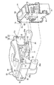
図8を併せて参照して、前記メインスイッチ17の一側に配置される前記開閉体遠隔操作部18は、前記シリンダ錠19から離隔した位置に配置される開閉体たとえば開閉可能な乗車用シートのロック状態を解除することを可能としたものであり、前記ケース部材29に設けられた一対の取付け腕部29d,29dにボルト66,66でそれぞれ取付けられる支持ケース67と、該支持ケース67から一部を外方に突出させるようにして前記支持ケース67に回動可能に支持される操作子68とを備える。
Referring also to FIG. 8, the opening / closing body
前記支持ケース67は、前記保護装置25のケーシング26側に配置される第1ケース部材69と、第1ケース部材69を前記ケーシング26との間に挟んで第1ケース部材69に係合される第2ケース部材70と、第1および第2ケース部材69,70に係合される第3ケース部材71とで構成され、第2ケース部材70が前記ケース部材29の前記取付け腕部29d,29dに締結される。
The
ところで前記カバー部材30と、前記ケース部材29との間の複数の弾発係合部34の少なくとも1つ、この実施の形態では1つの弾発係合部34は、前記開閉体遠隔操作部18における前記支持ケース67の第1ケース部材69で覆われる位置に配置されており、開閉体遠隔操作部18の支持ケース67が、前記カバー部材30の外面に当接するようにして前記ケース部材29に取付けられる。
By the way, at least one of the plurality of
また前記カバー部材30の外面には、前記キー孔22に挿入されるメカニカルキーの操作位置および前記マグネット錠27におけるマグネットキーの操作方向等が表示された意匠部材72が貼着されており、この意匠部材72の表面である意匠面72aと、前記開閉体遠隔操作部18における前記支持ケース67の表面のうち前記操作子68の周囲の意匠面67aとを合わせるために、前記カバー部材30の前記開閉体遠隔操作部18側に臨む面の2箇所には位置決め突起73,73が突設され、それらの位置決め突起73,73を嵌入させる位置決め孔74,74が、前記開閉体遠隔操作部18における支持ケース67の上端部に形成される。すなわち位置決め突起73および位置決め孔74から成る位置決め部75,75が、前記カバー部材30と、前記開閉体遠隔操作部18の支持ケース67との間に設けられる。
Further, a
前記操作子68は、図2で示すように、第1および第2ケース部材69,70間に設けられる支軸76で回動可能に支承されており、この操作子68を回動操作することで前記乗車用シートのロック状態が解除される。
As shown in FIG. 2, the
前記メインスイッチ17の回動操作に応じて回動する前記カム部材61と、前記開閉体遠隔操作部18との間には、前記カム部材61の回動位置に応じて前記操作子68の操作を許容する操作許容位置ならびに前記操作子68に係合して該操作子68の操作を規制する操作規制位置間で変位することを可能とした規制部材77が、カム部材61の外周に該規制部材77の一端を当接させるようにして設けられる。前記規制部材77は、前記ケース部材29との間に介装されるばね78(図4参照)で前記カム部材61の外周に摺接するように付勢される。また前記操作子68には、図2で示すように、前記規制部材77の前記カム部材61と反対側の端部を挿通、係合し得る係合孔68aが設けられる。
Between the
次にこの第1の実施の形態の作用について説明すると、シリンダ錠19の一端部を覆うように固定配置されるケース部材29と、該ケース部材29をシリンダ錠19とは反対側から覆うカバー部材30から成るケーシング26に、マグネット錠27が配設されるとともに、マグネット錠27の解錠時にシリンダ錠19のキー孔22を閉じる閉じ位置および開き位置間で作動するシャッター板28が収容されており、カバー部材30が合成樹脂から成るので、保護装置25の軽量化を図ることができる。しかもカバー部材30およびシャッター板28間に介在するようにして平板状に形成される金属製のプロテクタ47が、シャッター板28を覆うようにしてケース部材29に固定されるので、防盗性を高めることができる。
Next, the operation of the first embodiment will be described. The
またプロテクタ47がケース部材29にかしめ固定されるので、カバー部材30がケース部材29から外れてもプロテクタ47をケース部材29から外すことは困難でありプロテクタ47のケース部材29への確実な固定が可能となる。
Further, since the
またプロテクタ47に、シャッター板28に摺接する第1および第2の突条47b,47cが一体に形成されるので、シャッター板28の摺動抵抗を小さくして摺動性を高めることができる。
Further, since the first and
またカバー部材30が、複数箇所でケース部材29に弾発係合され、シリンダ錠19から離隔した位置に配置される開閉体のロック状態を解除することを可能とした開閉体遠隔操作部18が、前記複数箇所の弾発係合部34の少なくとも1つを覆って前記カバー部材30の外面に当接するようにして前記ケース部材29に取付けられるので、少なくとも1つの弾発係合部34の係合状態の解除を開閉体遠隔操作部18で阻止することができ、ケース部材29からのカバー部材30の外れ防止構造を簡単に構成することができる。
Further, the opening / closing body
またカバー部材30と、開閉体遠隔操作部18との間に、カバー部材30および開閉体遠隔操作部18の外面の意匠面72a,67aを合わせるための2つの位置決め部75が設けられるので、意匠面72a,67aのずれを防止することができる。
In addition, since the two
しかも保護装置25は、開き位置に在る前記シャッター板28に弾発的に当接する第1の当接部57aならびに前記シャッター板28が前記閉じ位置に在るときの前記ロータ40に弾発的に当接して該ロータ40の位置決めを果たしつつ前記ロータ40の回動に節度感を付与する第2の当接部57bを一体に有する弾性部材57を備えるので、1つの弾性部材57で開き位置にあるシャッター板28のがたつきを防止するとともに、前記シャッター板28が前記閉じ位置に在るときの前記ロータ40の位置決めを果たしつつ前記ロータ40の回動に節度感を付与することができ、部品点数を低減することができる。
Moreover, the
さらに前記弾性部材57が板ばねであるので、第1および第2の当接部57a,57bを有する弾性部材57を容易に形成することができる。
Furthermore, since the
本発明の第2の実施の形態について図9〜図11を参照しながら説明するが、上記第1の実施の形態に対応する部分には同一の参照符号を付して図示するのみとし、詳細な説明は省略する。 A second embodiment of the present invention will be described with reference to FIGS. 9 to 11, but the parts corresponding to the first embodiment are only given the same reference numerals and shown in detail. The detailed explanation is omitted.
マグネット錠79は、変則多角形状の前記嵌合凹部39が設けられるロータ80を有しており、このロータ80には、閉じ位置(図9および図10の位置)と、開き位置(図11の位置)と間で前記ロータ80とともに回動するシャッター板81が一体に形成される。
The
前記シャッター板81を覆う金属製のプロテクタ82が、カバー部材(図示せず)および前記シャッター板81間に介在するようにして平板状に形成される。このシャッター板81の2箇所には円形のかしめ孔83,84が形成され,ケース部材29には、前記かしめ孔83,84に個別に嵌合された状態でのかしめによって変形して前記プロテクタ82に係合するかしめ突部85,86が一体に設けられる。すなわちプロテクタ82は前記ケース部材29にかしめ固定される。
A
前記プロテクタ82には、前記シャッター板81に摺接する突条、たとえば2個の第1および第2の突条82a,82bが一体に形成される。また前記ロータ80に、その回動中心からずれた位置に配置される軸状の摘まみ部87が設けられ、この摘まみ部87はカバー部材の外方に突出する。
The
前記ロータ80の回動に節度感を付与するとともに、開き位置にある前記シャッター板81のがたつきを抑えるための弾性部材88が、前記ケース部材29に装着される。
An
この弾性部材88は、板ばねから成るものであり、前記シャッター板81が前記閉じ位置から前記開き位置に回動する途中で該シャッター板81の外周に弾発的に当接する当接部88aを有し、この当接部88aの先端部は、前記シャッター板81の外周に設けられる凹部89に、該シャッター板81が前記開き位置に在る状態で係合する。
The
この第2の実施の形態によっても、軽量化を図るとともに防盗性を高めることができ、プロテクタ82のケース部材29への確実な固定が可能となるとともに、シャッター板81の摺動抵抗を小さくして摺動性を高めることができる。
According to the second embodiment, the weight can be reduced and the anti-theft property can be improved, the
以上、本発明の実施の形態について説明したが、本発明は上記実施の形態に限定されるものではなく、特許請求の範囲に記載された本発明を逸脱することなく種々の設計変更を行うことが可能である。 Although the embodiments of the present invention have been described above, the present invention is not limited to the above-described embodiments, and various design changes can be made without departing from the present invention described in the claims. Is possible.
18・・・開閉体遠隔操作部
19・・・シリンダ錠
22・・・キー孔
25・・・保護装置
26・・・ケーシング
27,79・・・マグネット錠
28,81・・・シャッター板
29・・・ケース部材
30・・・カバー部材
34・・・弾発係合部
47,82・・・プロテクタ
47b,47c;82a,82b・・・突条
72a,67a・・・意匠面
75・・・位置決め部
18 ... Opening / closing body
Claims (5)
前記カバー部材(30)が合成樹脂から成り、前記カバー部材(30)および前記シャッター板(28,81)間に介在するようにして平板状に形成されるとともに前記シャッター板(28,81)に摺接する突条(47b,47c;82a,82b)が一体に形成される金属製のプロテクタ(47,82)が、前記シャッター板(28,81)を覆うようにして前記ケース部材(29)に固定されることを特徴とするシリンダ錠の保護装置。 A casing comprising a case member (29) fixedly arranged so as to cover one end of the cylinder lock (19) and a cover member (30) covering the case member (29) from the side opposite to the cylinder lock (19) ( 26) is provided with a magnetic lock (27, 79), a closed position for closing the key hole (22) of the cylinder lock (19) when the magnetic lock (27, 79) is unlocked, and the key hole In the protection device for the cylinder lock in which the shutter plate (28, 81) operating between the open positions for opening (22) is accommodated,
The cover member (30) is made of a synthetic resin, and is formed in a flat plate shape so as to be interposed between the cover member (30) and the shutter plate (28, 81), and on the shutter plate (28, 81). Metal protectors (47, 82), in which the slidable ridges (47b, 47c; 82a, 82b) are integrally formed , cover the case member (29) so as to cover the shutter plate (28, 81). Cylinder lock protection device characterized by being fixed.
前記カバー部材(30)が合成樹脂から成るとともに、複数箇所で前記ケース部材(29)に弾発係合され、前記カバー部材(30)および前記シャッター板(28,81)間に介在するようにして平板状に形成される金属製のプロテクタ(47,82)が、前記シャッター板(28,81)を覆うようにして前記ケース部材(29)に固定され、前記シリンダ錠(19)から離隔した位置に配置される開閉体のロック状態を解除することを可能とした開閉体遠隔操作部(18)が、前記複数箇所の弾発係合部(34)の少なくとも1つを覆うように前記カバー部材(30)の外面に当接して、前記ケース部材(29)に取付けられることを特徴とするシリンダ錠の保護装置。 A casing comprising a case member (29) fixedly arranged so as to cover one end of the cylinder lock (19) and a cover member (30) covering the case member (29) from the side opposite to the cylinder lock (19) ( 26) is provided with a magnetic lock (27, 79), a closed position for closing the key hole (22) of the cylinder lock (19) when the magnetic lock (27, 79) is unlocked, and the key hole In the protection device for the cylinder lock in which the shutter plate (28, 81) operating between the open positions for opening (22) is accommodated,
The cover member (30) is made of synthetic resin , and is elastically engaged with the case member (29) at a plurality of locations so as to be interposed between the cover member (30) and the shutter plates (28, 81). A metal protector (47, 82) formed in a flat plate shape is fixed to the case member (29) so as to cover the shutter plate (28, 81) and separated from the cylinder lock (19). The opening / closing body remote control section (18) capable of releasing the locked state of the opening / closing body disposed at a position covers the cover so as to cover at least one of the plurality of bullet engaging sections (34). A cylinder lock protection device, wherein the cylinder lock protection device is attached to the case member (29) in contact with an outer surface of the member (30).
The cylinder lock according to claim 2, wherein the protector (47, 82) is integrally formed with a ridge (47b, 47c; 82a, 82b) slidably contacting the shutter plate (28, 81). Protective device.
Priority Applications (5)
| Application Number | Priority Date | Filing Date | Title |
|---|---|---|---|
| JP2013099029A JP6029209B2 (en) | 2013-05-09 | 2013-05-09 | Cylinder lock protector |
| BR112015026980-0A BR112015026980B1 (en) | 2013-05-09 | 2014-04-18 | cylinder lock protection device |
| CN201480025712.7A CN105189890B (en) | 2013-05-09 | 2014-04-18 | The protection device of cylinder lock |
| EP14794338.5A EP2995752B1 (en) | 2013-05-09 | 2014-04-18 | Cylinder lock protecting device |
| PCT/JP2014/061072 WO2014181666A1 (en) | 2013-05-09 | 2014-04-18 | Cylinder lock protecting device |
Applications Claiming Priority (1)
| Application Number | Priority Date | Filing Date | Title |
|---|---|---|---|
| JP2013099029A JP6029209B2 (en) | 2013-05-09 | 2013-05-09 | Cylinder lock protector |
Publications (3)
| Publication Number | Publication Date |
|---|---|
| JP2014218842A JP2014218842A (en) | 2014-11-20 |
| JP2014218842A5 JP2014218842A5 (en) | 2015-06-25 |
| JP6029209B2 true JP6029209B2 (en) | 2016-11-24 |
Family
ID=51937554
Family Applications (1)
| Application Number | Title | Priority Date | Filing Date |
|---|---|---|---|
| JP2013099029A Active JP6029209B2 (en) | 2013-05-09 | 2013-05-09 | Cylinder lock protector |
Country Status (1)
| Country | Link |
|---|---|
| JP (1) | JP6029209B2 (en) |
Families Citing this family (1)
| Publication number | Priority date | Publication date | Assignee | Title |
|---|---|---|---|---|
| TWI608154B (en) * | 2016-04-06 | 2017-12-11 | Keyhole shielding device |
Family Cites Families (9)
| Publication number | Priority date | Publication date | Assignee | Title |
|---|---|---|---|---|
| JP3914043B2 (en) * | 2001-09-14 | 2007-05-16 | 株式会社ホンダロック | Protection device for cylinder lock for vehicle |
| JP2006233635A (en) * | 2005-02-25 | 2006-09-07 | Alpha Corp | Lock device for chain |
| JP4694315B2 (en) * | 2005-08-31 | 2011-06-08 | 川崎重工業株式会社 | Seat lock guard structure |
| JP4833699B2 (en) * | 2006-03-20 | 2011-12-07 | 株式会社中西エンジニアリング | Fastener and window shoji using the same |
| JP5084035B2 (en) * | 2008-03-14 | 2012-11-28 | 株式会社ニフコ | Latch mechanism |
| JP2011111822A (en) * | 2009-11-27 | 2011-06-09 | Yamaha Motor Co Ltd | Protection device of locking device for vehicle |
| JP5545745B2 (en) * | 2010-11-01 | 2014-07-09 | 朝日電装株式会社 | Ignition switch device |
| JP5844075B2 (en) * | 2011-06-17 | 2016-01-13 | テイ・エス テック株式会社 | Vehicle latch device |
| JP5723712B2 (en) * | 2011-07-31 | 2015-05-27 | 本田技研工業株式会社 | Mounting structure for vehicle unlocking mechanism |
-
2013
- 2013-05-09 JP JP2013099029A patent/JP6029209B2/en active Active
Also Published As
| Publication number | Publication date |
|---|---|
| JP2014218842A (en) | 2014-11-20 |
Similar Documents
| Publication | Publication Date | Title |
|---|---|---|
| EP1621705B1 (en) | Automotive door latch device | |
| JP4648167B2 (en) | Glove box equipment | |
| TWI384109B (en) | Cylinder lock protect apparatus | |
| JP4583464B2 (en) | Cylinder lock protector | |
| JP4100928B2 (en) | Cylinder lock protector | |
| JP4643073B2 (en) | Cylinder lock protector | |
| JP6029209B2 (en) | Cylinder lock protector | |
| JP2020519524A (en) | Locking devices, especially locking devices for motor vehicles | |
| JP5924777B2 (en) | Cylinder lock protector | |
| WO2014181666A1 (en) | Cylinder lock protecting device | |
| JPH1144132A (en) | Protecting device for cylinder lock | |
| JP6061093B2 (en) | Cylinder lock protector | |
| JP2021059923A (en) | Door latch device | |
| JP4530589B2 (en) | Protection device for cylinder lock for vehicle | |
| JP2015055094A5 (en) | ||
| JP6187908B2 (en) | Cylinder lock protector | |
| JP4418298B2 (en) | Locking device | |
| TWI695924B (en) | Protection device of cylinder lock and its assembling method | |
| CN113728364B (en) | Electronic key system for a motor vehicle | |
| JP6284416B2 (en) | Cylinder lock protector | |
| JP4815382B2 (en) | Glove box equipment | |
| JP4350034B2 (en) | Steering lock device | |
| US20220396325A1 (en) | Brake disk lock | |
| WO2016068000A1 (en) | Key unit | |
| JP5783466B2 (en) | Bicycle lock |
Legal Events
| Date | Code | Title | Description |
|---|---|---|---|
| A621 | Written request for application examination |
Free format text: JAPANESE INTERMEDIATE CODE: A621 Effective date: 20150421 |
|
| A521 | Request for written amendment filed |
Free format text: JAPANESE INTERMEDIATE CODE: A523 Effective date: 20150501 |
|
| A131 | Notification of reasons for refusal |
Free format text: JAPANESE INTERMEDIATE CODE: A131 Effective date: 20160323 |
|
| A521 | Request for written amendment filed |
Free format text: JAPANESE INTERMEDIATE CODE: A523 Effective date: 20160517 |
|
| TRDD | Decision of grant or rejection written | ||
| A01 | Written decision to grant a patent or to grant a registration (utility model) |
Free format text: JAPANESE INTERMEDIATE CODE: A01 Effective date: 20160921 |
|
| A61 | First payment of annual fees (during grant procedure) |
Free format text: JAPANESE INTERMEDIATE CODE: A61 Effective date: 20161014 |
|
| R150 | Certificate of patent or registration of utility model |
Ref document number: 6029209 Country of ref document: JP Free format text: JAPANESE INTERMEDIATE CODE: R150 |
|
| R250 | Receipt of annual fees |
Free format text: JAPANESE INTERMEDIATE CODE: R250 |
|
| R250 | Receipt of annual fees |
Free format text: JAPANESE INTERMEDIATE CODE: R250 |
|
| R250 | Receipt of annual fees |
Free format text: JAPANESE INTERMEDIATE CODE: R250 |
|
| R250 | Receipt of annual fees |
Free format text: JAPANESE INTERMEDIATE CODE: R250 |
|
| S533 | Written request for registration of change of name |
Free format text: JAPANESE INTERMEDIATE CODE: R313533 |
|
| R350 | Written notification of registration of transfer |
Free format text: JAPANESE INTERMEDIATE CODE: R350 |
|
| R250 | Receipt of annual fees |
Free format text: JAPANESE INTERMEDIATE CODE: R250 |