JP6028030B2 - Battery pack for handheld power tools - Google Patents
Battery pack for handheld power tools Download PDFInfo
- Publication number
- JP6028030B2 JP6028030B2 JP2014530859A JP2014530859A JP6028030B2 JP 6028030 B2 JP6028030 B2 JP 6028030B2 JP 2014530859 A JP2014530859 A JP 2014530859A JP 2014530859 A JP2014530859 A JP 2014530859A JP 6028030 B2 JP6028030 B2 JP 6028030B2
- Authority
- JP
- Japan
- Prior art keywords
- battery pack
- housing
- isolation
- space
- battery
- Prior art date
- Legal status (The legal status is an assumption and is not a legal conclusion. Google has not performed a legal analysis and makes no representation as to the accuracy of the status listed.)
- Active
Links
Images


Classifications
-
- H—ELECTRICITY
- H01—ELECTRIC ELEMENTS
- H01M—PROCESSES OR MEANS, e.g. BATTERIES, FOR THE DIRECT CONVERSION OF CHEMICAL ENERGY INTO ELECTRICAL ENERGY
- H01M50/00—Constructional details or processes of manufacture of the non-active parts of electrochemical cells other than fuel cells, e.g. hybrid cells
- H01M50/20—Mountings; Secondary casings or frames; Racks, modules or packs; Suspension devices; Shock absorbers; Transport or carrying devices; Holders
- H01M50/267—Mountings; Secondary casings or frames; Racks, modules or packs; Suspension devices; Shock absorbers; Transport or carrying devices; Holders having means for adapting to batteries or cells of different types or different sizes
-
- H—ELECTRICITY
- H01—ELECTRIC ELEMENTS
- H01M—PROCESSES OR MEANS, e.g. BATTERIES, FOR THE DIRECT CONVERSION OF CHEMICAL ENERGY INTO ELECTRICAL ENERGY
- H01M10/00—Secondary cells; Manufacture thereof
- H01M10/42—Methods or arrangements for servicing or maintenance of secondary cells or secondary half-cells
- H01M10/425—Structural combination with electronic components, e.g. electronic circuits integrated to the outside of the casing
- H01M10/4257—Smart batteries, e.g. electronic circuits inside the housing of the cells or batteries
-
- H—ELECTRICITY
- H01—ELECTRIC ELEMENTS
- H01M—PROCESSES OR MEANS, e.g. BATTERIES, FOR THE DIRECT CONVERSION OF CHEMICAL ENERGY INTO ELECTRICAL ENERGY
- H01M10/00—Secondary cells; Manufacture thereof
- H01M10/60—Heating or cooling; Temperature control
- H01M10/62—Heating or cooling; Temperature control specially adapted for specific applications
- H01M10/623—Portable devices, e.g. mobile telephones, cameras or pacemakers
- H01M10/6235—Power tools
-
- H—ELECTRICITY
- H01—ELECTRIC ELEMENTS
- H01M—PROCESSES OR MEANS, e.g. BATTERIES, FOR THE DIRECT CONVERSION OF CHEMICAL ENERGY INTO ELECTRICAL ENERGY
- H01M10/00—Secondary cells; Manufacture thereof
- H01M10/60—Heating or cooling; Temperature control
- H01M10/65—Means for temperature control structurally associated with the cells
- H01M10/655—Solid structures for heat exchange or heat conduction
- H01M10/6556—Solid parts with flow channel passages or pipes for heat exchange
-
- H—ELECTRICITY
- H01—ELECTRIC ELEMENTS
- H01M—PROCESSES OR MEANS, e.g. BATTERIES, FOR THE DIRECT CONVERSION OF CHEMICAL ENERGY INTO ELECTRICAL ENERGY
- H01M50/00—Constructional details or processes of manufacture of the non-active parts of electrochemical cells other than fuel cells, e.g. hybrid cells
- H01M50/20—Mountings; Secondary casings or frames; Racks, modules or packs; Suspension devices; Shock absorbers; Transport or carrying devices; Holders
- H01M50/204—Racks, modules or packs for multiple batteries or multiple cells
- H01M50/207—Racks, modules or packs for multiple batteries or multiple cells characterised by their shape
- H01M50/213—Racks, modules or packs for multiple batteries or multiple cells characterised by their shape adapted for cells having curved cross-section, e.g. round or elliptic
-
- H—ELECTRICITY
- H01—ELECTRIC ELEMENTS
- H01M—PROCESSES OR MEANS, e.g. BATTERIES, FOR THE DIRECT CONVERSION OF CHEMICAL ENERGY INTO ELECTRICAL ENERGY
- H01M2220/00—Batteries for particular applications
- H01M2220/30—Batteries in portable systems, e.g. mobile phone, laptop
-
- Y—GENERAL TAGGING OF NEW TECHNOLOGICAL DEVELOPMENTS; GENERAL TAGGING OF CROSS-SECTIONAL TECHNOLOGIES SPANNING OVER SEVERAL SECTIONS OF THE IPC; TECHNICAL SUBJECTS COVERED BY FORMER USPC CROSS-REFERENCE ART COLLECTIONS [XRACs] AND DIGESTS
- Y02—TECHNOLOGIES OR APPLICATIONS FOR MITIGATION OR ADAPTATION AGAINST CLIMATE CHANGE
- Y02E—REDUCTION OF GREENHOUSE GAS [GHG] EMISSIONS, RELATED TO ENERGY GENERATION, TRANSMISSION OR DISTRIBUTION
- Y02E60/00—Enabling technologies; Technologies with a potential or indirect contribution to GHG emissions mitigation
- Y02E60/10—Energy storage using batteries
Description
関連出願の相互参照
本出願は、2011年12月30日に出願された米国仮特許出願第61/581,957号に対する優先権を主張し、その内容は参照によりその全体が本明細書に組み込まれる
This application claims priority to US Provisional Patent Application No. 61 / 581,957, filed December 30, 2011, the contents of which are hereby incorporated by reference in their entirety. Be
ここで開示する技術は、手持式電動工具用のバッテリパックに関する。 The technology disclosed here relates to a battery pack for a hand-held power tool.
US2011/0114350A1は、手持式の電動工具に用いられるバッテリパックを開示する。このようなバッテリパックは、複数のバッテリセルと、複数のバッテリセルと電気的に接続された回路基板と、複数のバッテリセル及び回路基板を収容するハウジングを備えている。回路基板には、電動工具と電気的に接続するための接触式端子が設けられている。 US2011 / 0114350A1 discloses a battery pack used for a hand-held power tool. Such a battery pack includes a plurality of battery cells, a circuit board electrically connected to the plurality of battery cells, and a housing that houses the plurality of battery cells and the circuit board. The circuit board is provided with a contact terminal for electrical connection with the power tool.
US2003/0082439A1は、バッテリ駆動式の機器の使用に適したバッテリパックを開示する。このバッテリパックでは、複数の固定壁がハウジングに一体に形成されており、ハウジングに収容されたバッテリセルのバッテリ端子が、固定壁によって冷却風通路から物理的に隔離及び遮断されている。 US 2003/0082439 A1 discloses a battery pack suitable for use in battery-powered equipment. In this battery pack, a plurality of fixed walls are formed integrally with the housing, and the battery terminals of the battery cells accommodated in the housing are physically isolated and blocked from the cooling air passage by the fixed walls.
バッテリセル及び回路基板は、金属を含む電気機器の一種であるので、水分による腐食に弱い。従って、ハウジング内へ水分が浸入(浸透)することは、防止されることが好ましい。しかしながら、充電時や放電時に発生するバッテリパックの熱は、バッテリセルに回復不能なダメージを与える前に放出される必要があるので、ハウジングの全体を完全に密閉することは好ましくない。即ち、ハウジングの全体が完全に密閉されていれば、バッテリセルはオーバーヒートしてしまい、回復不能なダメージを負うことになる。従って、バッテリセルのオーバーヒートを防ぐためには、ハウジングに開口を形成しておき、その開口を通じて、ハウジング内の空間を自然換気又は強制換気する必要がある。しかしながら、ハウジングに開口を形成することで、水分がハウジング内へ浸入(浸透)するおそれが生じる。 Since the battery cell and the circuit board are a kind of electric equipment containing metal, they are vulnerable to moisture corrosion. Therefore, it is preferable to prevent moisture from entering (penetrating) into the housing. However, since the heat of the battery pack generated during charging or discharging needs to be released before irreparably damaging the battery cells, it is not preferable to completely seal the entire housing. That is, if the entire housing is completely sealed, the battery cell will be overheated, causing irreparable damage. Therefore, in order to prevent overheating of the battery cell, it is necessary to form an opening in the housing and to naturally or forcibly ventilate the space in the housing through the opening. However, by forming the opening in the housing, there is a risk that moisture may enter (penetrate) into the housing.
加えて、ハウジング内には、電動工具と電気的に接続する接触式端子が設けられている。接触式端子は、電動工具の接触式端子と物理的に接触する。そのため、ハウジングには、電動工具の接触式端子を受け入れる(が挿入される)ための開口を形成する必要がある。しかしながらこの場合でも、ハウジングに開口を形成することで、ハウジング内へ水分が浸入するおそれが生じる。 In addition, a contact terminal that is electrically connected to the power tool is provided in the housing. The contact terminal is in physical contact with the contact terminal of the power tool. Therefore, it is necessary to form an opening in the housing for receiving (inserting) the contact-type terminal of the electric tool. However, even in this case, there is a risk that moisture may enter the housing by forming the opening in the housing.
上記の理由に限られず、ハウジングに開口が形成されており、ハウジングの内部空間が外部空間(即ち、外部環境)と液体又は気体が流通可能となっていれば、ハウジング内へ水分が浸入(浸透)するおそれが必然的に生じる。そして、ハウジング内へ水分が浸入すれば、バッテリセル及び/又はバッテリセルが、腐食によって故障することが起こり得る。 Not limited to the above reasons, if an opening is formed in the housing, and if the internal space of the housing is capable of flowing liquid or gas with the external space (that is, the external environment), moisture can enter (permeate) the housing. ) Will inevitably occur. If moisture enters the housing, the battery cell and / or the battery cell may fail due to corrosion.
本技術は、例えば充電時や放電時にバッテリセルへ冷却風を供給するために、ハウジングの内部空間が外部空間と連通されている場合でも、上記のような事象を低減し、もって水分によるバッテリパックの故障を防止する。 The present technology reduces the above-described phenomenon even when the internal space of the housing is in communication with the external space in order to supply cooling air to the battery cells during charging or discharging, for example, and thus the battery pack due to moisture. To prevent malfunction.
上記した課題は、請求項1及び5に記載されたバッテリパックによって達成される。そして、発明の主題の改良事項は、従属請求項に記載されている。 The object described above is achieved by the battery pack described in claims 1 and 5. Improvements to the subject matter of the invention are set forth in the dependent claims.
本技術の一側面により、バッテリパックのハウジング内に、開放空間と隔離空間とがそれぞれ画定される。開放空間は、外部空間(例えば、バッテリパックのハウジングの外部環境)と連通する空間であり、隔離空間は、外部空間及び開放空間から隔離された空間である。その上で、バッテリセル及び/又は回路基板の水分又は外部の影響によって腐食しやすい部分を隔離空間に配置し、腐食に強い部分を開放空間に配置する。 According to one aspect of the present technology, an open space and an isolation space are respectively defined in the battery pack housing. The open space is a space communicating with an external space (for example, the external environment of the battery pack housing), and the isolation space is a space isolated from the external space and the open space. In addition, a portion that is easily corroded by moisture or external influences of the battery cell and / or the circuit board is disposed in the isolation space, and a portion that is resistant to corrosion is disposed in the open space.
あるいは、開放空間に配置する必要のある部分(例えば、回路基板において接触式端子が設けられた部分)のみを開放空間に配置し、その他の部分は隔離空間に配置する。この場合、バッテリセル及び/又は回路基板は、隔離空間と開放空間とを隔離する隔離壁を通過するので、隔離壁とバッテリセルとの間、隔離壁と回路基板との間、及び、隔離壁とバッテリセル及び回路基板との間の隙間が、腐食を抑制する上での問題となる。 Alternatively, only the part that needs to be arranged in the open space (for example, the part provided with the contact terminal on the circuit board) is arranged in the open space, and the other part is arranged in the isolation space. In this case, since the battery cell and / or the circuit board passes through the isolation wall that isolates the isolation space and the open space, the isolation wall and the battery cell, the isolation wall and the circuit board, and the isolation wall are separated. The gap between the battery cell and the circuit board becomes a problem in suppressing corrosion.
そこで、腐食のおそれを低減するために、本技術によると、隔離壁のバッテリセル及び/又は回路基板に接触する部分は、ハウジングを構成する一定の剛性を有する材料よりも、柔軟な又は弾力性のある材料(例えばゴム材料)で形成することが好ましい。隔離壁の適切な部分を柔軟な材料で形成すれば、隔離壁とバッテリセルとの間の隙間、隔離壁と回路基板との間の隙間、及び、隔離壁とバッテリセル及び回路基板との間の隙間を無くすことができる。 Therefore, in order to reduce the risk of corrosion, according to the present technology, the portion of the isolation wall that contacts the battery cell and / or the circuit board is more flexible or elastic than the material having a certain rigidity constituting the housing. It is preferable to form with a certain material (for example, rubber material). If an appropriate part of the isolation wall is formed of a flexible material, the clearance between the isolation wall and the battery cell, the clearance between the isolation wall and the circuit board, and between the isolation wall and the battery cell and the circuit board The gap can be eliminated.
よって、本技術の他の一側面では、手持式電動工具用のバッテリパックは、複数のバッテリセルと、複数のバッテリセルを収容するハウジングを備えることができる。ハウジングは、外部空間と連通している開放空間と、その開放空間から隔離された隔離空間を有することができる。ハウジング内では、開放空間と隔離空間との境界面に沿って、両空間を互いに隔離する隔離壁を設けることができる。各バッテリセルの一部は、開放空間に位置することができ、各バッテリセルの他の一部は、隔離空間に位置することができる。隔離壁のバッテリセルに接触する部分は、ハウジングよりも柔軟な及び/又は弾力性のある材料で形成することができる。ここでいう「バッテリセルの一部」とは、物理的に一体の一部分に限れられず、物理的に離れた二以上の部分であってもよい。 Therefore, in another aspect of the present technology, a battery pack for a hand-held power tool can include a plurality of battery cells and a housing that houses the plurality of battery cells. The housing can have an open space communicating with the external space and an isolated space isolated from the open space. In the housing, an isolation wall for isolating both spaces from each other can be provided along the boundary surface between the open space and the isolation space. A part of each battery cell can be located in the open space, and another part of each battery cell can be located in the isolated space. The portion of the isolation wall that contacts the battery cell can be formed of a material that is more flexible and / or elastic than the housing. The “part of the battery cell” here is not limited to a physically integrated part, but may be two or more parts physically separated.
本技術の他の一側面では、手持式電動工具用のバッテリパックは、複数のバッテリセルと、複数のバッテリセルと電気的に接続された回路基板と、複数のバッテリセル及び回路基板を収容するハウジングを備えることができる。ハウジングは、外部空間と連通している開放空間と、その開放空間から隔離された隔離空間を有することができる。ハウジング内には、開放空間と隔離空間との境界面に沿って、両空間を互いに隔離する隔離壁を設けることができる。回路基板の一部は、開放空間に位置することができ、回路基板の他の一部は、隔離空間に位置することができる。隔離壁の回路基板に接触する部分は、ハウジングよりも柔軟な及び/又は弾力性のある材料で形成することができる。 In another aspect of the present technology, a battery pack for a handheld power tool contains a plurality of battery cells, a circuit board electrically connected to the plurality of battery cells, and the plurality of battery cells and the circuit board. A housing can be provided. The housing can have an open space communicating with the external space and an isolated space isolated from the open space. In the housing, an isolation wall for isolating both spaces from each other can be provided along the boundary surface between the open space and the isolation space. A portion of the circuit board can be located in the open space, and another portion of the circuit board can be located in the isolation space. The portion of the isolation wall that contacts the circuit board can be formed of a material that is more flexible and / or elastic than the housing.
図1は、第1実施形態のバッテリパックの外観を示す。 FIG. 1 shows an appearance of the battery pack according to the first embodiment.
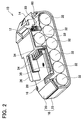
図2は、第1実施形態のバッテリパックを、バッテリセルの長手方向に垂直な断面で切断した切り取り図。 FIG. 2 is a cutaway view of the battery pack of the first embodiment cut along a cross section perpendicular to the longitudinal direction of the battery cell.
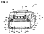
図3は、第1実施形態のバッテリパックを、バッテリセルの長手方向に平行な断面で切断した切り取り図。 FIG. 3 is a cutaway view of the battery pack of the first embodiment cut along a cross section parallel to the longitudinal direction of the battery cell.
図4は、第1実施形態のバッテリパックを、ハウジングの上ピースを取り除いて示す平面図。 FIG. 4 is a plan view showing the battery pack of the first embodiment with the upper piece of the housing removed.
図5は、第1実施形態のバッテリパックを、ハウジングを取り除いて示す斜視図。 FIG. 5 is a perspective view showing the battery pack of the first embodiment with the housing removed.
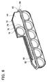
図6は、第1実施形態のバッテリパックの隔離壁及びシール部材を示す斜視図。 FIG. 6 is a perspective view showing an isolation wall and a seal member of the battery pack according to the first embodiment.
図7は、第2実施形態のバッテリパックを、バッテリセルの長手方向に垂直な断面で切断した切り取り図。 FIG. 7 is a cutaway view of the battery pack of the second embodiment cut along a cross section perpendicular to the longitudinal direction of the battery cell.
本技術の一実施形態では、開放空間に位置する各バッテリセルの一部に、バッテリセルの電極が設けられていることが好ましい。バッテリセルの電極を有する部分は水に弱いので、当該部分は隔離空間に配置することが好ましい。一方、他の部分は比較的に水分に強いので(例えば防水性シートで覆うこともできる)、開放空間に配置することが好ましい。それにより、ハウジング内に侵入(浸透)する水から電極を保護しつつ、開放空間を自然換気又は強制換気することによって、バッテリセルを冷却することができる。このような実施形態では、開放空間がバッテリセル(及びハウジング内部)の冷却風通路として機能する。よって、このような実施形態では、「冷却風通路」は、「解放空間」と置換可能な同義のものと解釈することができる。 In one embodiment of the present technology, it is preferable that a part of each battery cell located in the open space is provided with an electrode of the battery cell. Since the part which has the electrode of a battery cell is weak to water, it is preferable to arrange | position the said part in isolation space. On the other hand, since the other part is relatively resistant to moisture (for example, it can be covered with a waterproof sheet), it is preferably arranged in an open space. Accordingly, the battery cell can be cooled by naturally ventilating or forcibly ventilating the open space while protecting the electrode from water entering (penetrating) into the housing. In such an embodiment, the open space functions as a cooling air passage for the battery cell (and inside the housing). Therefore, in such an embodiment, the “cooling air passage” can be interpreted as a synonym that can be replaced with the “release space”.
本技術の一実施形態では、隔離壁が、複数のバッテリセルをそれぞれ通過させる複数の第1孔を、即ち、一つのバッテリセルについて一つの第1孔を有することが好ましい。この場合、各々の第1孔は、他の第1孔から独立して形成されていることが好ましい。そして、各々の第1孔の周縁(エッジ)が、ハウジングの材料よりも柔軟な及び/又は弾力性のある材料で形成されていることが好ましい。この構成によると、製造上の誤差によるような、隔離壁とバッテリセルとの間に生じる僅かな隙間を排除することができる。 In one embodiment of the present technology, it is preferable that the isolation wall has a plurality of first holes through which the plurality of battery cells pass, that is, one first hole for one battery cell. In this case, each first hole is preferably formed independently of the other first holes. And it is preferable that the periphery (edge) of each 1st hole is formed with the material more flexible and / or elastic than the material of a housing. According to this configuration, it is possible to eliminate a slight gap generated between the isolation wall and the battery cell due to a manufacturing error.
本技術の一実施形態では、隔離空間に配置された回路基板の一部に、回路基板とバッテリセルとを電気的に接続する導電線の一端が固定されていることが好ましい。それに加えて又は代えて、開放空間に配置された回路基板の一部に、電動工具と電気的に接続する接触式端子が設けられていることが好ましい。回路基板では、回路基板とバッテリセルとを電気的に接続する導電線の一端が固定されている部分が、比較的に水分に弱い。そのことから、回路基板の当該部分は、隔離空間に配置することが好ましい。また、回路基板のその他の部分についても、隔離空間に配置することが好ましい。ただし、電動工具用の接触式端子が設けられた部分については、開放空間に配置する必要がある。 In one embodiment of the present technology, it is preferable that one end of a conductive wire that electrically connects the circuit board and the battery cell is fixed to a part of the circuit board disposed in the isolation space. In addition to or instead of this, it is preferable that a part of the circuit board disposed in the open space is provided with a contact terminal that is electrically connected to the electric tool. In the circuit board, the portion where one end of the conductive wire that electrically connects the circuit board and the battery cell is fixed is relatively weak to moisture. Therefore, it is preferable to arrange the portion of the circuit board in the isolation space. Moreover, it is preferable to arrange other parts of the circuit board in the isolation space. However, it is necessary to arrange | position the part provided with the contact-type terminal for electric tools in open space.
上記した実施形態では、隔離壁が、回路基板を通過させる第2孔を有することが好ましい。この場合、第2孔の周縁(エッジ)は、ハウジングよりも柔軟な及び/又は弾力性のある材料で形成されていることが好ましい。この構成によると、製造上の誤差によるような、隔離壁と回路基板との間に生じる僅かな隙間を排除することができる。 In the above-described embodiment, it is preferable that the isolation wall has a second hole through which the circuit board passes. In this case, the peripheral edge (edge) of the second hole is preferably formed of a material that is more flexible and / or elastic than the housing. According to this configuration, it is possible to eliminate a slight gap generated between the isolation wall and the circuit board due to a manufacturing error.
上記した実施形態では、隔離壁が、複数のバッテリセルをそれぞれ通過させる複数の第1孔を、即ち、一つのバッテリセルについて一つの第1孔をさらに有することが好ましい。この場合、各々の第1孔は、他の第1孔及び第2孔から独立して形成されているとともに、各々の第1孔の周縁(エッジ)は、ハウジングよりも柔軟な及び又は弾力性のある材料で形成されていることが好ましい。この構成によると、製造上の誤差によるような、隔離壁とバッテリセルとの間に生じる僅かな隙間についても排除することができる。 In the above-described embodiment, it is preferable that the isolation wall further includes a plurality of first holes through which the plurality of battery cells pass, that is, one first hole for one battery cell. In this case, each first hole is formed independently of the other first hole and second hole, and the peripheral edge (edge) of each first hole is more flexible and / or elastic than the housing. It is preferable to be formed of a certain material. According to this configuration, it is possible to eliminate even a slight gap generated between the isolation wall and the battery cell due to a manufacturing error.
本発明の一実施形態では、隔離壁のハウジングに接触する部分についても、ハウジングよりも柔軟な及び/又は弾力性のある材料で形成されていることが好ましい。この構成によると、製造上の誤差によるような、隔離壁とハウジングとの間に生じる隙間を排除することができる。 In one embodiment of the present invention, it is preferable that the portion of the isolation wall that contacts the housing is also made of a material that is more flexible and / or elastic than the housing. According to this configuration, it is possible to eliminate a gap generated between the isolation wall and the housing due to a manufacturing error.
本発明の一実施形態では、ハウジングのつなぎ目が、隔離空間内に又は沿って位置することがある。この場合、隔離空間内には、ハウジングのつなぎ目(又はその一部)に沿って、シール部材を配置することが好ましい。そのシール部材は、ハウジングよりも柔軟な及び/又は弾力性のある材料で形成されていることが好ましい。それにより、ハウジングのつなぎ目から侵入する水分を排除することができる。一例ではあるが、シール部材の少なくとも一部は、隔離壁と一体で(例えばつなぎ目なしで)に形成することができる。当然に、隔離壁は、シール部材から独立した別部材として形成し、それらに固定又は接着されてもよい。 In one embodiment of the invention, the housing seam may be located in or along the isolation space. In this case, it is preferable to arrange a seal member in the isolation space along the joint (or part thereof) of the housing. The sealing member is preferably formed of a material that is more flexible and / or elastic than the housing. Thereby, the water | moisture content which penetrate | invades from the joint of a housing can be excluded. As an example, at least a portion of the seal member can be formed integrally with the isolation wall (eg, without seams). Naturally, the isolation wall may be formed as a separate member independent of the seal member and fixed or adhered thereto.
本発明の一実施形態では、隔離壁の全体が、ハウジングよりも柔軟な及び/又は弾力性のある材料で形成されていることが好ましい。この構成によると、隔離壁につなぎ目が形成されないので、隔離空間に侵入する僅かな水分も排除することができる。 In one embodiment of the present invention, the entire isolation wall is preferably made of a material that is more flexible and / or elastic than the housing. According to this configuration, since no joint is formed on the isolation wall, a slight amount of moisture entering the isolation space can be eliminated.
本発明の一実施形態では、上述したハウジングよりも柔軟な及び/又は弾力性のある材料として、天然ゴム又は合成ゴムその他のゴム材料あるいはエラストマを採用することができる。ゴム材料及びエラストマは、柔軟性に富むとともに、優れた遮水材料でもある。より詳細な例については後段で説明する。 In one embodiment of the present invention, natural rubber, synthetic rubber, other rubber materials, or elastomer can be adopted as a material that is more flexible and / or elastic than the housing described above. Rubber materials and elastomers are not only flexible but also excellent water shielding materials. A more detailed example will be described later.
本発明の一実施形態では、複数のバッテリセルが、互いに平行に配置されていることが好ましい。この構成によると、各バッテリセルの電極が互いに隣接して位置するので、複数のバッテリセルの端部に位置する電極をまとめて第1隔離空間に配置することができる。複数のバッテリセルの反対側の端部に位置する電極は、まとめて第2隔離空間に配置することができる。第2隔離空間は、第1隔離空間から分離され、第1隔離空間とは独立している。但し、第1隔離空間と第2隔離空間は、それらが外部空間から液体や気体の流動が禁止されている限り、液体や気体が流動できるように互いに接続されていてもよい。 In one Embodiment of this invention, it is preferable that the some battery cell is arrange | positioned mutually parallel. According to this configuration, since the electrodes of the battery cells are positioned adjacent to each other, the electrodes positioned at the end portions of the plurality of battery cells can be collectively arranged in the first isolation space. Electrodes located at opposite ends of the plurality of battery cells can be collectively arranged in the second isolation space. The second isolation space is separated from the first isolation space and is independent of the first isolation space. However, the first isolation space and the second isolation space may be connected to each other so that the liquid and the gas can flow as long as the flow of the liquid and the gas from the external space is prohibited.
本発明の一実施形態では、複数のバッテリセルを、少なくとも二段に配置するとともに、最上段には最も少ない数(例えば一本のみ)のバッテリセルを配置することが好ましい。この構成によると、最上段のバッテリセルが配置されない空間に、電動工具と接続するための端子、バッテリパックを電動工具にロックするロック部材、及び/又は、その他の電動工具の使用に適した各種の構成を配置することができる。一例ではあるが、端子を最上段のセルの一方側に配置するとともに、ロック部材を最上段のセルの他方側に配置することが好ましい。 In one embodiment of the present invention, it is preferable to arrange a plurality of battery cells in at least two stages and arrange the smallest number (for example, only one) of battery cells in the uppermost stage. According to this configuration, in a space where the uppermost battery cell is not arranged, a terminal for connecting to the power tool, a lock member for locking the battery pack to the power tool, and / or various types suitable for use of other power tools. Can be arranged. Although it is an example, it is preferable that the terminal is disposed on one side of the uppermost cell and the lock member is disposed on the other side of the uppermost cell.
図1−6を参照して、第1実施形態のバッテリパック10について説明する。第1実施形態のバッテリパック10は、手持式の電動工具用のバッテリパックであり、電動工具に電流(電力)を供給する。バッテリパック10は、電動工具に着脱可能に構成されている。バッテリパック10は、再充電可能となっており、繰り返し使用することができる。
With reference to FIGS. 1-6, the
図1から図4に示すように、バッテリパック10は、ハウジング18を備えている。ハウジング18は、プラスチック材料であって、好ましくは、柔軟性を示さない強度のプラスチック材料で形成されている。ハウジング18は、上ピース20と下ピース22を有する。上ピース20と下ピース22は、複数のねじ16によって互いに組み付けられている。上ピース20には、工具係合部26(突出部)と、複数のスリット24が形成されている。工具係合部26は、電動工具と機械的に係合(連結)することができる。本実施形態の工具係合部26は、一対のレール構造を有している。なお、工具係合部26は、二対以上のレール構造を有してもよいし、リンクやコネクタといった他の機械的な係合構造を有してもよい。各々のスリット24は、電動工具の接触式端子を受け入れる開口である。ハウジング18の内部空間は、各スリット24を介して外部空間(外部環境)と連通している。各スリット24の内側には、バッテリパック10の少なくとも一つの接触式端子34が設けられている。
As shown in FIGS. 1 to 4, the
図1から図5に示すように、バッテリパック10は、ロック部材12(例えばフック又はラッチ)と、ロック解除部材14(例えばボタン又はタブ)を備えている。ロック部材12は、電動工具の対応する係合部又は連結部と係合することによって、バッテリパック10を電動工具にロックする。ロック部材12は、弾性部材30によりロック位置(又はラッチ位置)に向けて付勢されており、ハウジング18の表面に対して、出入りすることができる。一例ではあるが、弾性部材30は、コイルスプリング又はその他のタイプの男性部材、例えば弾性変形可能な部材であってよい。ロック解除部材14は、バッテリパック10と電動工具との間のロックを解除するために、ユーザによって操作される(押される)操作部材である。ユーザがロック解除部材14を押すと、ロック部材12がハウジング18内へ引き込まれ、ユーザがロック解除部材14を戻すと、ロック部材12がハウジング18から突出し、電動工具のハウジングの内部に配置され、バッテリパック10が電動工具にロック(ラッチ)される。一例ではあるが、ロック部材12とロック解除部材14は、単一の部品によって繋ぎ目なく一体に形成されている。
As shown in FIGS. 1 to 5, the
図1、図2に示すように、ハウジング18には、通気口28が形成又は画定されている。通気口28は、ハウジング18の内部空間を換気するための開口である。ハウジング18の内部空間は、通気口28を通じて外部空間(外部環境)と連通している。例えば、通気口28は、充電器に設けられたファンが供給する冷却風を受け入れる。加えて又は代えて、ハウジング18の自然換気又は強制換気を、通気口28を通じて行うことができる。
As shown in FIGS. 1 and 2, a
図2から図5に示すように、バッテリパック10は、複数のバッテリセル32を備えている。複数のバッテリセル32は、ハウジング18内に収容されている。一例ではあるが、本実施形態のバッテリパック10は、7本のバッテリセル32を備えており、各々のバッテリセル32は、リチウムイオンセルである。ただし、バッテリセル32の数は7本に限定されず、バッテリセル32の種類もリチウムイオンセルに限定されず、例えば、ニッケルカドミウムセル又はニッケル水素セルであってもよい。複数のバッテリセル32は、金属といった導電性材料で形成された複数の接続板38を介して、直列に接続されている。各バッテリセル32の公称電圧は3.6ボルトであり、バッテリパック10の全体としての公称電圧は25.2ボルトである。
As shown in FIGS. 2 to 5, the
複数のバッテリセル32は、その長手方向が互いに平行となるように配置されている。複数のバッテリセル32は、二段に並べて配置されている。下段には6本のバッテリセル32が配置されており、上段には1本のバッテリセル32が配置されている。上段のバッテリセル32の一方側には、接触式端子34が配置されており、上段のバッテリセル32の他方側には、ロック部材12が配置されている。接触式端子34とロック部材12の間に少なくとも一方のバッテリセル32を配置することで、バッテリパック10のサイズを小型化することができる。なお、上段に配置するバッテリセル32の本数と、下段に配置するバッテリセル32の本数は、特に限定されない。例えば、全7本のバッテリセル32を有するバッテリパック10の場合、上段に二本のバッテリセル32を配置し、下段に五本のバッテリセル32を配置してもよい。あるいは、上段に三本のバッテリセル32を配置し、下段に四本のバッテリセル32を配置してもよい。さらに、上段に配置するバッテリセル32の本数が、下段に配置するバッテリセル32の本数よりも多くてもよい。
The plurality of
図2から図5に示すように、バッテリパック10は、バッテリセルホルダ60(以下、セルホルダ60)を有している。セルホルダ60は、プラスチック材料で形成されている。セルホルダ60は、底のない箱形状を有している。なお、セルホルダ60は、底のある箱形状であってもよいし、その他の形状であってもよい。セルホルダ60には、複数のバッテリセル32を一定の相対位置関係で保持し得る各種の形状及び構造を採用することができる。図3、5に示すように、セルホルダ60の各側面60aには、複数の孔62が形成されている。各々の孔62は、セルホルダ60外部へ伸びるバッテリセル32を保持している。各バッテリセル32の両端面32aは、セルホルダ60の外側に位置しており、各バッテリセル32の中間部分32bは、セルホルダ60の内側に位置している。セルホルダ60には、通気口28が形成又は画定されており、通気口28は、ハウジング18に形成又は画定された通気口28と対応し、連通している。セルホルダ60の内部空間は、外部空間(外部環境)と連通しており、バッテリセル32を冷却する冷却風の通路となっている。
As shown in FIGS. 2 to 5, the
図1から図5に示すように、バッテリパック10は、回路基板36を備えている。回路基板36には、上述した複数の接触式端子34が設けられている。回路基板36は、複数の導電線40を介して、複数のバッテリセル32と電気的に接続されている。複数のバッテリセル32は、回路基板36を通じて、複数の接触式端子34へ電気的に接続されている。その他、回路基板36には、少なくとも一つのマイクロプロセッサ、少なくとも一つのメモリ及び/又は記憶装置、各種のセンサ及び回路パターン(回路パターンは、回路基板上の各種の部品や回路基板に取り付けられた各種の部品を電気的に接続する)が設けられている。
As shown in FIGS. 1 to 5, the
図3、図4に示すように、バッテリパック10は、一対の隔離壁44を備えている。一対の隔離壁44は、ハウジング18内に位置している。二つの隔離壁44は、セルホルダ60の両側面60aに沿ってそれぞれ配置されている。一例であるが、各々の隔離壁44は、ハウジング18を形成する材料よりも柔軟な材料で形成されている。一例であるが、本実施形態の隔離壁44は、ハウジング18を形成するプラスチック材料よりも柔軟なゴム材料で形成されている。以下でより詳細に説明する。各々の隔離壁44は、ハウジング18の内部空間を気密に区分しており、バッテリセル32の長手方向の両端において、内部空間が気密に、又は実質的に気密に区分されている。図3、図4に示すように、ハウジング18の内部空間は、一対の隔離壁44に挟まれた冷却風通路54(以下、開放空間54)と、その両側に位置する二つの隔離空間52に区画されている。開放空間54は、通気口28や複数のスリット24を通じて、外部空間(外部環境)と連通している。それに対して、各々の隔離空間52は、隔離壁44とハウジング18によって囲まれており、外部空間(外部環境)及び開放空間54から気密に隔離されている。
As shown in FIGS. 3 and 4, the
隔離空間52は、実質的に密閉されているので(完全に又は気密にシールされていなければ)、隔離空間52内の圧力は、隔離空間52内の温度に応じて変化する。例えばバッテリパック10の放電時や充電時は、バッテリセル32の発生する熱により、隔離空間52内の温度が上昇するので、隔離空間52内の圧力も上昇する。このとき、隔離空間52と開放空間54との間で圧力差が大きくなりすぎると、隔離壁44による気密性が破壊され、例えば隔離壁44とハウジング18との間から空気が漏れてしまう。この場合、その後に隔離空間52内の温度が低下したときに(つまり、バッテリパック10が使用されていないときに)、隔離空間52が開放空間54及び外部空間(外部環境、つまり雰囲気圧力)に対して負圧となり、水分を含む外気が隔離空間52に侵入することになってしまう。このような水分の侵入という問題に対し、本技術は、隔離空間52内の圧力変動を、隔離空間52の気密性が破壊されない程度に抑制することを提案する。
Since the
圧力変動を抑制又は制限するために、本実施例の隔離壁44は、上述又は後述するように、弾性材料、例えばゴム材料で形成されており、柔軟性及び/又は弾性を有している。そのことから、各々の隔離壁44(又はその少なくとも一部)は、対応する隔離空間52内の圧力変化に応じて変形することができ、一種のダイヤフラムとして機能する。隔離壁44の少なくとも一部が、増大する圧力に応じて拡張することができると、隔離空間52内の圧力変動を抑制することができる。上記に加え、又は代えて、隔離壁44の弾性は、隔離壁44の少なくとも一部を形成する材質だけでなく、隔離壁44の形状によって実現することもできる。具体的には、隔離壁44の一部又は全体に凹部又は凸部を形成してもよいし、隔離壁44の一部を他の部分よりも薄くすることも有効である。
In order to suppress or limit the pressure fluctuation, the
上述したように、本実施形態のバッテリパック10は、ハウジング18内に開放空間54と二つの隔離空間52を有している。開放空間54は、通気口28を通じて外部空間と連通している。従って、開放空間54を自然換気(受動的な換気)又は強制換気することにより、バッテリセル32の中間部分に冷却風を送ることによって、バッテリセル32のオーバーヒートを防止することができる。ただし、ハウジング18内に開放空間54を設けると、ハウジング18内に水分が浸入(浸透)するおそれが生じる。そこで、本実施形態のバッテリパック10は、ハウジング18内に隔離空間52を有し、バッテリセル32及び/又は回路基板36において水分に弱い部分(例えば、バッテリセル32の長手方向両端の金属端子)が、隔離空間52内に配置されている。
As described above, the
一例ではあるが、本実施形態では、全てのバッテリセル32の各端面32aが隔離空間52に配置されている。これは、バッテリセル32の端面32aには正極及び負極端子(金属端子)が設けられており、当該端子やそれに固定された接続板38が水分に弱いためである。また、図4に示すように、回路基板36の両端部分36a(長手方向の両端部分)も、隔離空間52に配置されている。回路基板36の両端部分36aには、回路基板36とバッテリセル32とを電気的に接続する導電線40の一端40aが、はんだ付けによって固定されており、当該部分が水分に弱いためである。なお、導電線40を用いることなく、導電板である接続板38を、回路基板36の一端を直接的に接続することによって、バッテリセル32と回路基板36を電気的に接続してもよい。あるいは、導電線40に代えて、フレキシブル基板(フレキシブルプリント基板)により、バッテリセル32と回路基板36を電気的に接続してもよい。いずれにしても、バッテリセル32と回路基板36とを電気的に接続する導電体の一端が固定されている回路基板36の部分を、隔離空間52に配置するとよい。
Although it is an example, in this embodiment, each
一方、バッテリセル32の中間部分32bは、開放空間54に配置されている。バッテリセル32の中間部分32bは、一又は複数の防水性シートによって被覆されており、水分には比較的に強くなっている(即ち、バッテリセルの金属部分や導電性の金属板/ワイヤと比較して、耐腐食性が強い)。また、回路基板36の中間部分36bも、開放空間54に配置されている。バッテリセル32の中間部分32bは、上ピース20の表面に配置された複数の接触式端子34に近接する開放空間54に配置されている。
On the other hand, the
図3、図4に示すように、バッテリパック10は、シール部材42を備え入る。一例であるが、本実施形態のシール部材42は、弾性材料であって、例えばゴム材料で形成されている。シール部材42を形成する材料は、隔離壁44を形成する材料と同じでもよいし、異なってもよい。シール部材42を形成する材料の代表的な例は後述する。
As shown in FIGS. 3 and 4, the
シール部材42は、ハウジング18の上ピース20と下ピース22との間のつなぎ目に沿って配置されている。シール部材42は、ハウジング18のつなぎ目から隔離空間52に侵入する水分を排除する。本実施形態では、上ピース20と下ピース22との間のつなぎ目のうち、隔離空間52に位置するつなぎ目にのみ、シール部材42が設けられている。即ち、開放空間54に位置するつなぎ目に、シール部材42は設けられていない。ただし、他の実施形態として、つなぎ目の全長に亘って一つの(エンドレスの)シールやガスケットを配置するなど、開放空間54に位置するつなぎ目にもシール部材42を設けてもよい。シール部材42の材料は、特に限定されないが、ハウジング18を形成する材料よりも柔軟な材料(例えばゴム材料あるいはエラストマ)であることが好ましく、この点は後段で説明を加える。
The
図6を参照して、隔離壁44及びシール部材42の主要な構造について説明する。隔離壁44の周縁(エッジ)72は、ハウジング18の内面に当接する部分である。当該部分は、弾性材料、例えばゴム材料で形成されており、ハウジング18よりも柔軟である。それにより、隔離壁44とハウジング18との間に生じる僅かな隙間も排除される。さらに、隔離壁44の周縁72は、他の部分よりも厚くなっているとともに、溝74が形成されている。この構成により、隔離壁44とハウジング18との間の気密性が高められている。
The main structures of the
隔離壁44は、複数の第1孔76を有している。複数の第1孔76は、互いに独立しており、即ち、各々の第1孔76を区分する中実な部分が存在する。各々の第1孔76は、対応する一つのバッテリセル32を、通過させるように受け入れる。バッテリセル32に接触する第1孔76の周縁(エッジ)78は、例えばゴム材料で形成されており、ハウジング18よりも柔軟である。それにより、隔離壁44とバッテリセル32との間に生じる僅かな隙間も排除され、シールされる。さらに、第1孔76の周縁78は、他の部分よりも厚くなっている。この構成により、隔離壁44とバッテリセル32との間により広いシール領域が形成され、隔離壁44とバッテリセル32との間の気密性が高められている。
The
隔離壁44は、第2孔80を有している。第2孔80は、各々の第1孔76から独立している。第2孔80は回路基板36を通過させるように受け入れる。回路基板36に接触する第2孔80の周縁82は、例えばゴム材料で形成されており、ハウジング18よりも柔軟である。それにより、隔離壁44と回路基板36との間に生じる僅かな隙間も排除され、シールされる。さらに、第2孔80の周縁82は、他の部分よりも厚くなっている。この構成により、隔離壁44と回路基板36との間により広いシール領域が形成され、隔離壁44と回路基板36との間の気密性が高められている。
The
本実施形態のシール部材42は、隔離壁44と一体に形成されており、即ち、同じ材料で形成されているとともに、それらの間につなぎ目が存在しない。シール部材42は、フランジ88を備えている。フランジ88は、ハウジング18の上ピース20と下ピース22を互いに組み付けるときに、上ピース20と下ピース22の間に挟み込まれる。それにより、上ピース20と下ピース22との間のつなぎ目に生じる僅かな隙間も排除され、シールされる。なお、シール部材42は、必ずしも隔離壁44と一体に形成する必要はない。即ち、シール部材42は、隔離壁44と別に形成され、接着又はその他の方法で隔離壁44に固定されてもよい。また、上ピース20と下ピース22との間のつなぎ目が十分に気密であれば、シール部材42の一部又は全部を省略することができる。
The
本実施形態の隔離壁44は、その全体がゴム材料で形成されているが、隔離壁44の一部のみを、ゴム材料又はその他のハウジング18よりも柔軟な材料で形成してもよい。この場合は、バッテリセル32に接触する部分78と、ハウジング18に接触する部分72と、回路基板36に接触する部分82の少なくとも一つを任意の組み合わせで、ハウジング18よりも柔軟な材料で形成するとよい。即ち、隔離壁44の他の一部は、ハウジング18と同じ材料又はハウジング18よりも硬質な材料で形成してもよい。この場合、隔離壁44は二以上の部品を組み合わせて形成してもよい。ハウジング18よりも柔軟な材料としては、天然ゴム若しくは合成ゴムといったゴム材料、エラストマ又は後述する任意の弾性材料を採用することができる。
The
図7を参照して、第2実施形態のバッテリパック110について説明する。本実施形態のバッテリパック110は、第1実施形態のバッテリパック10と比較して、そのバッテリセル32の本数が異なっている。その他の構成については、第1実施形態のバッテリパック10と同様である。第1実施形態と共通する構成には、同一の符号を付しており、ここでは説明を省略する。なお、本実施例のバッテリパック110においても、ハウジング18内に隔離空間52と開放空間54が画定されており、バッテリセル32の一部及び回路基板36の一部が隔離空間52内に配置されている。
With reference to FIG. 7, the
図7に示すように、本実施形態のバッテリパック110は、14本のバッテリセル32を備えている。一例ではあるが、14本のバッテリセル32は、二本ずつ並列に接続され、7対の並列に接続されたバッテリセル32が直列に接続されている。14本のバッテリセル32は、互いに平行に配置されている。14本のバッテリセル32は、三段に並べて配置されている。最下段には7本のバッテリセル32が配置されており、中断には6本のバッテリセル32が配置されており、最上段には1本のみのバッテリセル32が配置されている。最上段のバッテリセル32の一方側には、接触式端子34が配置されており、最上段のバッテリセル32の他方側には、ロック部材12が配置されている。この構造については、第1実施形態のバッテリパック10と共通している。接触式端子34とロック部材12の間に少なくとも一方のバッテリセル32を配置することで、バッテリパック10のサイズを小型化することができる。一例ではあるが、各バッテリセル32は、リチウムイオンセルであり、その公称電圧は3.6ボルトである。従って、本実施形態のバッテリパック110の全体としての公称電圧は、25.2ボルトとなっている。
As shown in FIG. 7, the
ハウジング18(即ち、上ピース(ハーフ)20と下ピース(ハーフ)22)は、ポリカーボネート(PC)材料、又は、同様の剛性及び耐久性を有する他の材料で形成することが好ましい。PCのヤング率は2.2GPa(ISO規格)である。概して、ハウジング18は、1.0−3.0GPaの範囲内のヤング率、より好ましくは2.0−2.5GPaの範囲内のヤング率を示すことが好ましい。
The housing 18 (i.e., the upper piece (half) 20 and the lower piece (half) 22) is preferably formed of a polycarbonate (PC) material or other material having similar stiffness and durability. The Young's modulus of PC is 2.2 GPa (ISO standard). In general, the
隔離壁44の少なくとも一部(又は全部)及び/又はシール部材42は、ハウジング18よりも、柔らかく、弾性に富み、柔軟な材料で形成することが好ましい。前述したように、隔離壁44及び/又はシール部材42は、弾性材料、例えばゴム材料で形成することが好ましく、ゴムパッキン(ガスケット)であることがより好ましい。概して言えば、ゴム材料の硬さは、ISO規格で定められた方法に基づき、デュロメータを用いて決定される。隔離壁44の一部又は全体に関して、A型デュロメータ計(ShoreA)による好適な硬さの範囲は、70から90の間である。
It is preferable that at least a part (or all) of the
上述したように、エラストマ又はゴム材料の具体的な構成は、その材料が適度な弾性、強度、耐久性、水分をシールする特性を有する限り、特に限定されない。よって、限定されないが、本技術では、天然ゴム又は合成ゴム、例えば、ポリイソプレン、ポリブタチレン、クロロプレンゴム、ブチルゴム(ハロゲン化ブチルゴムを含む)、スチレン−ブタチレンゴム、ニトリルゴム(ハロゲン化ニトリルゴムを含む)といった不飽和性のゴム材料、あるいはそれらの混合材料を好適に用いることができる。あるいは、限定されないが、本技術では、飽和性のゴム材料、例えば、エチレンゴム、プロピレンゴム、ポリアクリルゴム、シリコーンゴム、フルオロシリコンゴム、フルオラストマゴム、パルフルオラストマゴム、ポリエチルブロックアミド、クロロスルホロネイテッドポリエチレン、エチレンビニルアセテートなどや、それらの混合材料を好適に用いることができる。ゴム材料は、加硫されたものでもよいし、未加硫のものであってもよい。 As described above, the specific configuration of the elastomer or rubber material is not particularly limited as long as the material has appropriate elasticity, strength, durability, and moisture sealing properties. Therefore, although not limited thereto, in the present technology, natural rubber or synthetic rubber such as polyisoprene, polybutylene, chloroprene rubber, butyl rubber (including halogenated butyl rubber), styrene-butylene rubber, nitrile rubber (including halogenated nitrile rubber), etc. An unsaturated rubber material or a mixed material thereof can be suitably used. Alternatively, but not limited to, the present technology provides a saturable rubber material such as ethylene rubber, propylene rubber, polyacrylic rubber, silicone rubber, fluorosilicone rubber, fluorolastomer rubber, parfluorolastomer rubber, polyethylblock amide, chloro Sulfonated polyethylene, ethylene vinyl acetate, and the like, and mixed materials thereof can be suitably used. The rubber material may be vulcanized or unvulcanized.
概して、熱硬化性のエラストマが好ましいが、適切な条件下において、熱可塑性のエラストマ、例えば、スチレンブロック共重合体、ポリオレフィン、ポリエステル、ポリアミドなどや、それらの混合材料を用いることもできる。 In general, thermosetting elastomers are preferred, but thermoplastic elastomers such as styrene block copolymers, polyolefins, polyesters, polyamides, etc., and mixtures thereof may be used under appropriate conditions.
エラストマの技術分野においてよく知られているように、エラストマ材料にはいかなる周知のフィラーを組み合わせることもできる。 As is well known in the elastomer art, any known filler can be combined with the elastomeric material.
本明細書で開示される本技術のさらなる代表的な実施形態には下記が含まれる。 Additional exemplary embodiments of the technology disclosed herein include the following.
1.手持式電動工具用のバッテリパックであって、
複数のバッテリセルと、
前記バッテリセルを収容するとともに、外部空間と連通している開放空間とその開放空間から隔離された隔離空間を有するハウジングと、
前記ハウジング内において前記開放空間と前記隔離空間との境界面に沿って配置され、両空間を互いに隔離している隔離壁を備え、
各バッテリセルの一部は前記開放空間に位置するとともに、各バッテリセルの他の一部は前記隔離空間に位置しており、
前記隔離壁の前記バッテリセルに接触する部分は、前記ハウジングよりも柔軟な材料で形成されている、バッテリパック。
1. A battery pack for a hand-held power tool,
Multiple battery cells;
A housing containing the battery cell and having an open space communicating with the external space and an isolated space isolated from the open space;
An isolation wall disposed along the boundary surface between the open space and the isolation space in the housing, and isolating both spaces from each other;
A part of each battery cell is located in the open space, and another part of each battery cell is located in the isolation space,
The battery pack in which the part which contacts the said battery cell of the said isolation wall is formed with the material more flexible than the said housing.
2.前記隔離空間に位置する各バッテリセルの一部には、バッテリセルの電極が設けられている、形態1に係るバッテリパック。 2. The battery pack according to aspect 1, wherein a part of each battery cell located in the isolation space is provided with an electrode of the battery cell.
3.前記隔離壁は、複数のバッテリセルをそれぞれ通過させる複数の第1孔を有し、
各々の第1孔は、他の第1孔から独立して形成されているとともに、各々の第1孔の周縁は、前記ハウジングよりも柔軟な材料で形成されている、形態1又は2に係るバッテリパック。
3. The isolation wall has a plurality of first holes through which a plurality of battery cells pass,
Each 1st hole is formed independently of the other 1st hole, and the periphery of each 1st hole is formed with a softer material than the said housing, According to form 1 or 2 Battery pack.
4.前記バッテリセルと電気的に接続されているとともに、前記ハウジングに収容されている回路基板をさらに備え、
前記回路基板の一部は前記開放空間に位置するとともに、前記回路基板の他の一部は前記隔離空間に位置しており、
前記隔離壁の前記回路基板に接触する部分も、前記ハウジングよりも柔軟な材料で形成されている、形態1から3のいずれか一つに係るバッテリパック。
4). A circuit board electrically connected to the battery cell and housed in the housing;
A part of the circuit board is located in the open space, and another part of the circuit board is located in the isolation space;
The battery pack according to any one of aspects 1 to 3, wherein a portion of the isolation wall that contacts the circuit board is also formed of a material that is more flexible than the housing.
5.前記隔離空間に配置された回路基板の一部には、前記回路基板と前記バッテリセルとを電気的に接続する導電体の一端が固定されている、形態4に係るバッテリパック。 5. The battery pack according to aspect 4, wherein one end of a conductor that electrically connects the circuit board and the battery cell is fixed to a part of the circuit board disposed in the isolation space.
6.前記導電体は、導電線、導電板、又はフレキシブル基板のうちの少なくとも一つである、形態5に係るバッテリパック。 6). The battery pack according to aspect 5, wherein the conductor is at least one of a conductive wire, a conductive plate, and a flexible substrate.
7.前記開放空間に配置された回路基板の一部には、前記電動工具と電気的に接続する接触式端子が設けられている、形態4又は5に係るバッテリパック。 7). The battery pack according to embodiment 4 or 5, wherein a part of the circuit board disposed in the open space is provided with a contact terminal that is electrically connected to the power tool.
8.前記隔離壁は、前記回路基板を通過させる第2孔を有し、
第2孔の周縁は、前記ハウジングよりも柔軟な材料で形成されている、形態4から7のいずれか一つに係るバッテリパック。
8). The isolation wall has a second hole through which the circuit board passes;
The battery pack according to any one of Embodiments 4 to 7, wherein the periphery of the second hole is formed of a material that is more flexible than the housing.
9.前記隔離壁は、前記複数のバッテリセルをそれぞれ通過させる複数の第1孔をさらに有し、
各々の第1孔は、他の第1孔及び第2孔から独立して形成されているとともに、各々の第1孔の周縁は、前記ハウジングよりも柔軟な材料で形成されている、形態8に係るバッテリパック。
9. The isolation wall further includes a plurality of first holes through which the plurality of battery cells pass,
Each of the first holes is formed independently of the other first and second holes, and the periphery of each of the first holes is formed of a material that is more flexible than the housing. A battery pack according to the present invention.
10.前記隔離壁の前記ハウジングに接触する部分も、前記ハウジングよりも柔軟な材料で形成されている、形態1から9のいずれか一つに係るバッテリパック。 10. The battery pack according to any one of Embodiments 1 to 9, wherein a portion of the isolation wall that contacts the housing is also formed of a material that is more flexible than the housing.
11.前記隔離壁は、前記隔離空間内の圧力変化に応じて変形し、前記隔離空間内の圧力変化を抑制する、形態1から10のいずれか一つに係るバッテリパック。 11. The battery pack according to any one of Embodiments 1 to 10, wherein the isolation wall is deformed according to a pressure change in the isolation space and suppresses a pressure change in the isolation space.
12.前記隔離壁の少なくとも一部は、他の部分よりも薄く形成されているか、又は凹凸状に成形されており、前記隔離空間内の圧力変化に応じて膨出したり収縮したりする、形態11に係るバッテリパック。 12 At least a part of the isolation wall is formed thinner than the other part, or is formed in an uneven shape, and swells or contracts according to a pressure change in the isolation space. Such a battery pack.
13.前記隔離壁は、少なくとも一つの凹部又は凸部を有しており、当該凹部又は凸部が前記隔離空間内の圧力変化に応じて変形する、形態11に係るバッテリパック。 13. The battery pack according to the eleventh aspect, wherein the isolation wall has at least one concave portion or convex portion, and the concave portion or convex portion is deformed according to a pressure change in the isolation space.
14.シール部材をさらに備え、
前記シール部材は、前記隔離空間内に位置し、前記ハウジングのつなぎ目に沿って配置され、前記ハウジングよりも柔軟な材料で形成されている、形態1から13のいずれか一つに係るバッテリパック。
14 A seal member,
The battery pack according to any one of aspects 1 to 13, wherein the seal member is located in the isolation space, is disposed along a joint of the housing, and is formed of a material that is more flexible than the housing.
15.前記シール部材は、前記隔離壁と一体に形成されている、形態14に係るバッテリパック。
15. The battery pack according to
16.前記隔離壁の全体が、前記ハウジングよりも柔軟な材料で形成されている、形態1から15のいずれか一つに係るバッテリパック。 16. The battery pack according to any one of Embodiments 1 to 15, wherein the whole isolation wall is formed of a material that is more flexible than the housing.
17.前記ハウジングよりも柔軟な材料とは、天然ゴム又は合成ゴムその他のゴム材料又はエラストマである、形態1から16のいずれか一つに係るバッテリパック。 17. The battery pack according to any one of Embodiments 1 to 16, wherein the material softer than the housing is natural rubber, synthetic rubber, other rubber material, or elastomer.
手持式電動工具用のバッテリパックであって、
複数のバッテリセルと、
前記バッテリセルと電気的に接続された回路基板と、
前記バッテリセル及び前記回路基板を収容するとともに、外部空間と連通している開放空間とその開放空間から隔離された隔離空間を有するハウジングと、
前記ハウジング内において前記開放空間と前記隔離空間との境界面に沿って配置され、両空間を互いに隔離している隔離壁を備え、
前記回路基板の一部は前記開放空間に位置するとともに、各バッテリセルの他の一部は前記隔離空間に位置しており、
前記隔離壁の前記回路基板に接触する部分は、前記ハウジングよりも柔軟な材料で形成されている、バッテリパック。
A battery pack for a hand-held power tool,
Multiple battery cells;
A circuit board electrically connected to the battery cell;
A housing that houses the battery cell and the circuit board, and has an open space communicating with an external space and an isolated space isolated from the open space;
An isolation wall disposed along the boundary surface between the open space and the isolation space in the housing, and isolating both spaces from each other;
A part of the circuit board is located in the open space, and another part of each battery cell is located in the isolation space,
The part of the isolation wall that contacts the circuit board is formed of a material that is more flexible than the housing.
19.前記隔離壁は、前記回路基板を通過させる第2孔を有し、
第2孔の周縁は、前記ハウジングよりも柔軟な材料で形成されている、形態18に係るバッテリパック。
19. The isolation wall has a second hole through which the circuit board passes;
The battery pack according to
20.前記隔離空間に配置された回路基板の一部には、前記回路基板と前記バッテリセルとを電気的に接続する導電体の一端が固定されている、形態18又は19に係るバッテリパック。
20. The battery pack according to
21.前記導電体は、導電線、導電板、又はフレキシブル基板のうちの少なくとも一つである、形態20に係るバッテリパック。
21. The battery pack according to
22.前記開放空間に配置された回路基板の一部には、前記電動工具と電気的に接続する接触式端子が設けられている、形態18から21のいずれか一つに係るバッテリパック。
22. The battery pack according to any one of
以上、本発明の代表的で非限定的な実施例について、図面を参照しながら詳細に説明した。この詳細な説明は、単に、本教示の好ましい態様を実施するためのさらなる詳細を、当業者に教示するためのものであって、本発明の範囲を限定することを意図したものではない。さらに、以上及び以下に開示する付加的な特徴及び教示の各々を、個別に又は他の特徴及び教示と組み合わせて利用することで、改良された動力工具のためのバッテリパック及びその製造及び使用する方法が提供される。 The exemplary and non-limiting examples of the present invention have been described in detail with reference to the drawings. This detailed description is merely for the purpose of teaching those skilled in the art additional details for practicing the preferred embodiments of the present teachings and is not intended to limit the scope of the invention. Further, each of the additional features and teachings disclosed above and below may be utilized individually or in combination with other features and teachings to provide a battery pack for improved power tools and their manufacture and use. A method is provided.
さらに、上記の詳細な説明に開示する特徴及びステップの組合せは、本発明を最も広い意味で実施するという観点では、必ずしも必要なものではなく、単に、本発明の代表的な実施例を詳細に説明するために教示されたものである。さらに、後述する代表的な例のさまざまな特徴は、後の様々な独立請求項及び従属請求項と同様に、具体的にかつ明示的に列挙されていない態様で組み合わせることが可能であり、それによって、本教示に係る有用な実施形態をさらに実現することができる。 Furthermore, the combinations of features and steps disclosed in the above detailed description are not necessarily required in terms of practicing the invention in its broadest sense, but merely details of representative embodiments of the invention. It has been taught to explain. Furthermore, the various features of the representative examples described below, like the various independent and dependent claims that follow, can be combined in a manner that is not specifically and explicitly recited, Can further realize useful embodiments according to the present teachings.
本明細書及び/又は特許請求の範囲に開示されたすべての特徴は、請求項に記載の主題を限定するためだけでなく、実施形態及び/又は請求項における特徴の特定の組合せとは無関係に、本来の書面による開示を目的として、それぞれ個別に独立して開示されることを意図したものである。さらに、すべての数値範囲又は集合体の表示についても、請求項に記載の主題を限定するためだけでなく、本来の書面による開示の目的のために、すべての取り得る中間の値又は中間の実体を開示することを意図したものである。 All features disclosed in the specification and / or in the claims are not limited to the subject matter recited in the claims, but are independent of the specific combination of features in the embodiments and / or claims. Intended to be disclosed individually and independently for the purpose of original written disclosure. In addition, all numerical ranges or collections may be expressed in terms of all possible intermediate values or entities, not only for the purpose of limiting the claimed subject matter, but also for the purpose of original written disclosure. Is intended to be disclosed.
10、110:バッテリパック
12:ロック部材
14:ロック解除部材
18:ハウジング
20:ハウジングの上ピース
22:ハウジングの下ピース
24:スリット
26:工具係合部
28:通気口
30:弾性部材
32:バッテリセル
32a:バッテリセルの端面
32b:バッテリセルの中間部分
34:接触式端子
36:回路基板
36a:回路基板の両端部分
36b:回路基板の中間部分
38:接続板
40:導電線
40a:導電線の一端
42:シール部材
44:隔離壁
52:隔離空間
54:開放空間
60:セルホルダ
60a:セルホルダの側面
62:セルホルダの孔
72:隔離壁の周縁
74:隔離壁の溝
76:隔離壁の第1孔
78:第1孔の周縁
80:隔離壁の第2孔
82:第2孔の周縁
88:シール部材のフランジ
10, 110: Battery pack
12: Lock member 14: Lock release member
18: Housing 20: Upper piece of housing
22: Lower piece of housing 24: Slit
26: Tool engaging portion 28: Vent
30: Elastic member 32: Battery cell
32a:
34: Contact type terminal 36: Circuit board
36a: both end portions of circuit board 36b: intermediate portion of circuit board
38: Connection plate 40: Conductive wire
40a: One
44: Isolation wall 52: Isolation space
54: Open space 60: Cell holder
60a: Cell holder side surface 62: Cell holder hole
72: Perimeter of isolation wall 74: Groove of isolation wall
76:
80:
88: Flange of seal member
Claims (19)
剛性を有する材料で構成され、その内部に、外部環境と通気的に接続された冷却風通路と、その冷却風通路から隔離された少なくとも一つの隔離空間とを有するハウジングと、
前記ハウジング内に配置され、前記隔離空間を前記冷却風通路から分離遮断している少なくとも一つの隔離壁と、
前記ハウジング内に配置された複数のバッテリセルと、
その端部が前記少なくとも一つの隔離空間内に位置し、かつ、その中間部が前記冷却風通路に隣接して位置するように、前記少なくとも一つの隔離壁を通過して伸びている回路基板と、を備え、
前記回路基板に接触する前記少なくとも一つの隔離壁の少なくとも一つの第2部分が、前記ハウジングの剛性を有する材料よりも、柔軟性及び/又は弾力性の高い材料で形成されている、バッテリパック。 A battery pack used in the power tool of a hand-held,
Is formed of a material having a stiffness in its interior, and Haujin grayed having a cooling air passage path connected external environment and the ventilation to, and between at least one isolated sky that is isolated from the cooling air passage,
At least one isolation wall disposed within the housing and separating and isolating the isolation space from the cooling air passage;
A plurality of Batterise Le disposed within said housing,
Located in the end said at least one isolated space, and so that its intermediate portion is located adjacent said cooling air passage path, the at least one circuit group extending through the partition wall of the A board ,
At least one second part portion of the at least one partition wall contacts the circuit board is the even from a material having a stiffness of Haujin grayed, are formed of a flexible and / or highly elastic material, Battery pack.
その少なくとも一つの接触式端子は、前記回路基板の中間部に設けられている、請求項1から3のいずれか一項に記載のバッテリパック。 Further comprising at least one contact pin to the corresponding contact terminals and the electrical contact of the power tool,
At least one contact terminal, the provided in an intermediate portion of a circuit board, a battery pack according to any one of claims 1 to 3.
前記回路基板は、前記第2孔を通過して伸びており、
前記少なくとも一つの第2部分は、前記第2孔の周縁である、請求項1から4のいずれか一項に記載のバッテリパック。 A second hole is formed in the isolation wall ,
It said circuit board is extended through the second hole,
Wherein the at least one second part component of the a peripheral edge of the second hole, the battery pack according to any one of claims 1 to 4.
前記複数のバッテリセルには、前記少なくとも一つの隔離壁の複数の第1部分がそれぞれ接触しており、
少なくとも前記複数の第1部分は、前記ハウジングの剛性を有する材料よりも、柔軟性及び/又は弾力性の高い材料で形成されており、
前記ハウジングは、上側半部材と下側半部材とで構成されており、
前記ハウジングの剛性を有する材料よりも、柔軟性及び/又は弾力性の高い材料で形成されたシールが、少なくとも部分的に、前記隔離空間内であって、前記上側半部材と下側半部材との接続部分に沿って設けられている、請求項1から5のいずれか一項に記載のバッテリパック。 The plurality of battery cells are disposed in the housing such that end portions thereof are located in the at least one isolation space and intermediate portions thereof are located adjacent to the cooling air passage .
A plurality of first portions of the at least one isolation wall are in contact with the plurality of battery cells,
At least the plurality of first portions are formed of a material having higher flexibility and / or elasticity than a material having rigidity of the housing,
The housing is composed of an upper half member and a lower half member,
A seal formed of a material that is more flexible and / or elastic than the rigid material of the housing is at least partially within the isolation space, the upper half member and the lower half member The battery pack according to any one of claims 1 to 5, wherein the battery pack is provided along a connecting portion.
前記複数のバッテリセルは、それぞれ前記複数の第1孔を通過して伸びており、
前記第1部分は、前記第1孔の周縁である、請求項6から8のいずれか一項に記載のバッテリパック。 A plurality of first holes spaced apart from each other are formed in the at least one isolation wall,
Wherein the plurality of Batterise Le are extended respectively through said plurality of first holes,
Said first part component, the a periphery of the first hole, the battery pack according to any one of claims 6 to 8.
剛性を有する材料で構成され、その内部に、外部環境と通気的に接続された冷却風通路と、その冷却風通路から隔離された少なくとも一つの隔離空間とを有するハウジングと、A housing that is made of a material having rigidity and has a cooling air passage that is connected to the outside environment in an air-permeable manner and at least one isolation space that is isolated from the cooling air passage;
前記ハウジング内に配置され、前記隔離空間を前記冷却風通路から分離遮断している少なくとも一つの隔離壁と、At least one isolation wall disposed within the housing and separating and isolating the isolation space from the cooling air passage;
その端部が前記少なくとも一つの隔離空間内に位置し、かつ、その中間部が前記冷却風通路に隣接して位置するように、前記ハウジング内に配置された複数のバッテリセルと、を備え、A plurality of battery cells disposed in the housing such that an end thereof is located in the at least one isolation space and an intermediate portion thereof is located adjacent to the cooling air passage;
前記複数のバッテリセルには、前記少なくとも一つの隔離壁の複数の第1部分がそれぞれ接触しており、A plurality of first portions of the at least one isolation wall are in contact with the plurality of battery cells,
少なくとも前記複数の第1部分は、前記ハウジングの剛性を有する材料よりも、柔軟性及び/又は弾力性の高い材料で形成されており、At least the plurality of first portions are formed of a material having higher flexibility and / or elasticity than a material having rigidity of the housing,
前記ハウジングは、上側半部材と下側半部材とで構成されており、The housing is composed of an upper half member and a lower half member,
前記ハウジングの剛性を有する材料よりも、柔軟性及び/又は弾力性の高い材料で形成されたシールが、少なくとも部分的に、前記隔離空間内であって、前記上側半部材と下側半部材との接続部分に沿って設けられており、A seal formed of a material that is more flexible and / or elastic than the rigid material of the housing is at least partially within the isolation space, the upper half member and the lower half member It is provided along the connection part of
前記隔離壁は、前記隔離空間内の圧力の増加及び減少に応じて拡張及び収縮するように構成された少なくとも一つの弾性部を備える、バッテリパック。The isolation wall includes at least one elastic portion configured to expand and contract in response to an increase and decrease in pressure in the isolation space.
Applications Claiming Priority (3)
| Application Number | Priority Date | Filing Date | Title |
|---|---|---|---|
| US201161581957P | 2011-12-30 | 2011-12-30 | |
| US61/581,957 | 2011-12-30 | ||
| PCT/JP2012/008287 WO2013099227A1 (en) | 2011-12-30 | 2012-12-25 | Battery pack for use with hand-held electric power tool |
Publications (3)
| Publication Number | Publication Date |
|---|---|
| JP2015509258A JP2015509258A (en) | 2015-03-26 |
| JP2015509258A5 JP2015509258A5 (en) | 2016-01-28 |
| JP6028030B2 true JP6028030B2 (en) | 2016-11-16 |
Family
ID=47559622
Family Applications (1)
| Application Number | Title | Priority Date | Filing Date |
|---|---|---|---|
| JP2014530859A Active JP6028030B2 (en) | 2011-12-30 | 2012-12-25 | Battery pack for handheld power tools |
Country Status (5)
| Country | Link |
|---|---|
| US (1) | US9337453B2 (en) |
| JP (1) | JP6028030B2 (en) |
| CN (1) | CN204424329U (en) |
| DE (1) | DE212012000235U1 (en) |
| WO (1) | WO2013099227A1 (en) |
Families Citing this family (29)
| Publication number | Priority date | Publication date | Assignee | Title |
|---|---|---|---|---|
| JP5916514B2 (en) * | 2012-05-24 | 2016-05-11 | リョービ株式会社 | Battery pack |
| US10131042B2 (en) | 2013-10-21 | 2018-11-20 | Milwaukee Electric Tool Corporation | Adapter for power tool devices |
| US9634503B2 (en) * | 2014-02-26 | 2017-04-25 | Makita Corporation | Battery chargers |
| US9929353B2 (en) | 2014-04-02 | 2018-03-27 | Universal Display Corporation | Organic electroluminescent materials and devices |
| JP6261449B2 (en) * | 2014-05-30 | 2018-01-17 | ダイキョーニシカワ株式会社 | Battery module |
| DE102015216029A1 (en) | 2015-08-21 | 2017-02-23 | Robert Bosch Gmbh | battery Pack |
| CN106549122B (en) * | 2015-09-18 | 2020-01-03 | 光宝电子(广州)有限公司 | Waterproof battery accommodating structure |
| CN105140442A (en) * | 2015-09-23 | 2015-12-09 | 江苏绿伟锂能有限公司 | Lithium battery module used for handheld electric mower |
| DE102017211012A1 (en) * | 2017-06-29 | 2019-01-03 | Robert Bosch Gmbh | Hand tool |
| CN109546027A (en) | 2017-09-22 | 2019-03-29 | 苏州宝时得电动工具有限公司 | Battery pack and electric tool component |
| KR102002489B1 (en) * | 2017-12-13 | 2019-07-23 | 계양전기 주식회사 | Battery for electric tool having termanal of different material |
| DE102018104339A1 (en) * | 2018-02-26 | 2019-08-29 | Metabowerke Gmbh | Battery pack and electric hand tool |
| EP3792007A4 (en) * | 2018-05-07 | 2022-04-27 | Positec Power Tools (Suzhou) Co., Ltd | Battery pack and electric tool assembly |
| US11611124B2 (en) * | 2018-07-18 | 2023-03-21 | Black & Decker Inc. | Battery pack |
| JP2020170683A (en) | 2019-04-05 | 2020-10-15 | 株式会社マキタ | Battery pack |
| USD937760S1 (en) | 2019-06-12 | 2021-12-07 | Techtronic Cordless Gp | Terminal block of a battery pack |
| USD937761S1 (en) | 2019-06-12 | 2021-12-07 | Techtronic Cordless Gp | Terminal block of a battery pack |
| USD937759S1 (en) | 2019-06-12 | 2021-12-07 | Techtronic Cordless Gp | Terminal block of a battery pack |
| USD937195S1 (en) | 2019-06-12 | 2021-11-30 | Techtronic Cordless Gp | Interface of a battery pack |
| USD911802S1 (en) | 2019-06-12 | 2021-03-02 | Techtronic Cordless Gp | Interface of a power tool |
| DE102019119242A1 (en) * | 2019-07-16 | 2021-01-21 | Metabowerke Gmbh | Battery pack |
| US11670819B2 (en) | 2019-08-09 | 2023-06-06 | Techtronic Cordless Gp | Battery pack including staggered battery pack terminals |
| US11145929B2 (en) | 2019-08-09 | 2021-10-12 | Techtronic Cordless Gp | Battery pack |
| US11575176B2 (en) * | 2019-08-09 | 2023-02-07 | Techtronic Cordlesss GP | Battery pack |
| US11901570B2 (en) * | 2019-09-16 | 2024-02-13 | Black & Decker Inc. | Battery pack |
| DE102019220202A1 (en) * | 2019-12-19 | 2021-06-24 | Robert Bosch Gmbh | Battery device for a battery pack of a hand machine tool |
| DE102020109105A1 (en) * | 2020-04-01 | 2021-10-07 | Einhell Germany Ag | Battery pack for an electrical device |
| TWI740666B (en) * | 2020-09-26 | 2021-09-21 | 朝程工業股份有限公司 | Battery pack |
| KR20220048797A (en) | 2020-10-13 | 2022-04-20 | 주식회사 엘지에너지솔루션 | Battery pack and vehicle comprising the battery pack |
Family Cites Families (9)
| Publication number | Priority date | Publication date | Assignee | Title |
|---|---|---|---|---|
| JP3569152B2 (en) * | 1998-10-15 | 2004-09-22 | 株式会社マキタ | battery pack |
| DE10003247B4 (en) * | 1999-01-29 | 2005-02-24 | Sanyo Electric Co., Ltd., Moriguchi | Power source, equipped with rechargeable batteries |
| US6410185B1 (en) * | 1999-02-15 | 2002-06-25 | Sony Corporation | Battery device for loading on moving body |
| JP3805664B2 (en) * | 2001-11-01 | 2006-08-02 | 株式会社マキタ | Battery pack |
| US7253585B2 (en) | 2002-11-22 | 2007-08-07 | Milwaukee Electric Tool Corporation | Battery pack |
| JP4606139B2 (en) | 2004-11-30 | 2011-01-05 | 三洋電機株式会社 | Pack battery |
| JP5173227B2 (en) | 2007-03-30 | 2013-04-03 | 三洋電機株式会社 | Pack battery |
| JP5370709B2 (en) * | 2007-10-29 | 2013-12-18 | 日立工機株式会社 | Battery pack and electric tool equipped with the same |
| EP2316145B1 (en) | 2008-08-14 | 2021-04-14 | Clarios Advanced Solutions LLC | Battery module with sealed vent chamber |
-
2012
- 2012-12-25 US US14/369,706 patent/US9337453B2/en active Active
- 2012-12-25 CN CN201290001106.8U patent/CN204424329U/en not_active Expired - Lifetime
- 2012-12-25 DE DE201221000235 patent/DE212012000235U1/en not_active Expired - Lifetime
- 2012-12-25 WO PCT/JP2012/008287 patent/WO2013099227A1/en active Application Filing
- 2012-12-25 JP JP2014530859A patent/JP6028030B2/en active Active
Also Published As
| Publication number | Publication date |
|---|---|
| WO2013099227A1 (en) | 2013-07-04 |
| JP2015509258A (en) | 2015-03-26 |
| CN204424329U (en) | 2015-06-24 |
| DE212012000235U1 (en) | 2014-08-06 |
| US20140349143A1 (en) | 2014-11-27 |
| US9337453B2 (en) | 2016-05-10 |
Similar Documents
| Publication | Publication Date | Title |
|---|---|---|
| JP6028030B2 (en) | Battery pack for handheld power tools | |
| US11283120B2 (en) | Battery pack | |
| US11128010B2 (en) | Battery pack | |
| US9979215B2 (en) | Portable energy storage and power supply system | |
| KR101743697B1 (en) | Battery module having separated cooling path and venting path and battery pack including the same | |
| US9293747B2 (en) | Multi cell carriers | |
| JP4606139B2 (en) | Pack battery | |
| US8895182B2 (en) | Battery pack and power tool provided with the same | |
| US20140302377A1 (en) | Battery pack for electric power tool | |
| US11394086B2 (en) | Battery module and connection member | |
| JP2005197192A (en) | Pack cell and its assembling method | |
| KR20140000770A (en) | Battery module for secondary battery | |
| KR20190091631A (en) | Vibration resistant battery cell holder and battery pack with the same | |
| JP2020087873A (en) | Battery pack | |
| JP4518958B2 (en) | Battery module | |
| KR101746765B1 (en) | Cartridge for secondary battery and battery module including the same | |
| JP6318979B2 (en) | Battery unit | |
| JP2017188375A (en) | Battery pack | |
| JP2010282854A (en) | Gas discharge device of battery pack | |
| JP4303672B2 (en) | Fuel cell stack | |
| KR20150037380A (en) | Tray for curved surface-structured battery cell | |
| JP7425268B2 (en) | Battery packs and electric vehicles | |
| KR20160113079A (en) | Tray for curved surface-structured battery cell | |
| JP2012138295A (en) | Secondary battery and method for reusing secondary battery |
Legal Events
| Date | Code | Title | Description |
|---|---|---|---|
| A521 | Request for written amendment filed |
Free format text: JAPANESE INTERMEDIATE CODE: A523 Effective date: 20151202 |
|
| A621 | Written request for application examination |
Free format text: JAPANESE INTERMEDIATE CODE: A621 Effective date: 20151202 |
|
| A131 | Notification of reasons for refusal |
Free format text: JAPANESE INTERMEDIATE CODE: A131 Effective date: 20160830 |
|
| A521 | Request for written amendment filed |
Free format text: JAPANESE INTERMEDIATE CODE: A523 Effective date: 20160914 |
|
| TRDD | Decision of grant or rejection written | ||
| A01 | Written decision to grant a patent or to grant a registration (utility model) |
Free format text: JAPANESE INTERMEDIATE CODE: A01 Effective date: 20161011 |
|
| A61 | First payment of annual fees (during grant procedure) |
Free format text: JAPANESE INTERMEDIATE CODE: A61 Effective date: 20161017 |
|
| R150 | Certificate of patent or registration of utility model |
Ref document number: 6028030 Country of ref document: JP Free format text: JAPANESE INTERMEDIATE CODE: R150 |
|
| R250 | Receipt of annual fees |
Free format text: JAPANESE INTERMEDIATE CODE: R250 |
|
| R250 | Receipt of annual fees |
Free format text: JAPANESE INTERMEDIATE CODE: R250 |
|
| R250 | Receipt of annual fees |
Free format text: JAPANESE INTERMEDIATE CODE: R250 |
|
| R250 | Receipt of annual fees |
Free format text: JAPANESE INTERMEDIATE CODE: R250 |
|
| R250 | Receipt of annual fees |
Free format text: JAPANESE INTERMEDIATE CODE: R250 |