JP6027534B2 - Dynamic radial shaft seal assembly with combined dust removal thrust pad - Google Patents
Dynamic radial shaft seal assembly with combined dust removal thrust pad Download PDFInfo
- Publication number
- JP6027534B2 JP6027534B2 JP2013529165A JP2013529165A JP6027534B2 JP 6027534 B2 JP6027534 B2 JP 6027534B2 JP 2013529165 A JP2013529165 A JP 2013529165A JP 2013529165 A JP2013529165 A JP 2013529165A JP 6027534 B2 JP6027534 B2 JP 6027534B2
- Authority
- JP
- Japan
- Prior art keywords
- seal assembly
- shaft seal
- radial shaft
- lip
- dynamic radial
- Prior art date
- Legal status (The legal status is an assumption and is not a legal conclusion. Google has not performed a legal analysis and makes no representation as to the accuracy of the status listed.)
- Expired - Fee Related
Links
Images


Classifications
-
- F—MECHANICAL ENGINEERING; LIGHTING; HEATING; WEAPONS; BLASTING
- F16—ENGINEERING ELEMENTS AND UNITS; GENERAL MEASURES FOR PRODUCING AND MAINTAINING EFFECTIVE FUNCTIONING OF MACHINES OR INSTALLATIONS; THERMAL INSULATION IN GENERAL
- F16J—PISTONS; CYLINDERS; SEALINGS
- F16J15/00—Sealings
- F16J15/16—Sealings between relatively-moving surfaces
- F16J15/32—Sealings between relatively-moving surfaces with elastic sealings, e.g. O-rings
- F16J15/3248—Sealings between relatively-moving surfaces with elastic sealings, e.g. O-rings provided with casings or supports
- F16J15/3252—Sealings between relatively-moving surfaces with elastic sealings, e.g. O-rings provided with casings or supports with rigid casings or supports
- F16J15/3256—Sealings between relatively-moving surfaces with elastic sealings, e.g. O-rings provided with casings or supports with rigid casings or supports comprising two casing or support elements, one attached to each surface, e.g. cartridge or cassette seals
-
- F—MECHANICAL ENGINEERING; LIGHTING; HEATING; WEAPONS; BLASTING
- F16—ENGINEERING ELEMENTS AND UNITS; GENERAL MEASURES FOR PRODUCING AND MAINTAINING EFFECTIVE FUNCTIONING OF MACHINES OR INSTALLATIONS; THERMAL INSULATION IN GENERAL
- F16J—PISTONS; CYLINDERS; SEALINGS
- F16J15/00—Sealings
- F16J15/16—Sealings between relatively-moving surfaces
- F16J15/34—Sealings between relatively-moving surfaces with slip-ring pressed against a more or less radial face on one member
- F16J15/3436—Pressing means
- F16J15/3456—Pressing means without external means for pressing the ring against the face, e.g. slip-ring with a resilient lip
Landscapes
- Engineering & Computer Science (AREA)
- General Engineering & Computer Science (AREA)
- Mechanical Engineering (AREA)
- Sealing With Elastic Sealing Lips (AREA)
- Sealing Devices (AREA)
- Sealing Of Bearings (AREA)
Description
発明の背景
1.技術分野
本発明は、一般に動的径方向シャフトシールに関し、より特定的には、軸方向に延びるごみ除去リップおよびスラストパッドを有する動的径方向シャフトシールに関する。
Background of the Invention TECHNICAL FIELD The present invention relates generally to dynamic radial shaft seals and, more particularly, to dynamic radial shaft seals having an axially extending debris lip and thrust pad.
2.関連技術
動的径方向シャフトシールは、環状外側シール部品と、環状内側シール部品とをしばしば含む。外側シール部品は、密閉すべき開口の周囲に、ハウジング内に搭載されるように構成され、摩耗スリーブを含む内側シール部品は、開口を通じて延びるシャフトとともに回転可能に、かつシャフト上に搭載されるように構成される。外側シール部品は、典型的には、ハウジングへ圧入するようにサイズ決めされる金属円筒部を有する外側金属ケースを含み、当該円筒部から径方向に内側に向かって脚部が延びる。さらに、典型的には、弾性体が、脚部に取り付けられ、弾性体のメインシールリップが脚部の端から径方向に内側に向かって延びて、摩耗スリーブの円筒形転走面に当接し、これに対するシールを設ける。さらに、弾性体は、典型的には、1つ以上のごみ除去リップを含み、ごみおよびその他の汚れがメインシールリップに到達およびこれを迂回することを防ぐ。ごみ除去リップは、摩耗スリーブの円筒形転走面に対して重なるように構成され、摩耗スリーブの円筒形転走面から径方向に外側に向かって延びる摩耗スリーブのフランジにも重なるように構成される。メインシールリップおよびごみ除去リップに加えて、金属ケースの脚部と摩耗スリーブのフランジとの間に別個のスラストパッドを設けることが知られている。典型的には、スラストパッドは、1つ以上のごみ除去リップから径方向に外側に向けられる。そのため、スラストパッドを収容するためにシールアセンブリの径方向の範囲(envelope)を必ず増大させるか、または1つ以上のごみ除去リップを取り除く。そうすると、今度は、ごみおよびその他の汚れの侵入を抑制する可能性が低くなってしまう。
2. Related Art Dynamic radial shaft seals often include an annular outer seal part and an annular inner seal part. The outer seal component is configured to be mounted within the housing about the opening to be sealed, and the inner seal component including the wear sleeve is rotatably mounted on and on the shaft extending through the opening. Configured. The outer seal part typically includes an outer metal case having a metal cylinder sized to be press fit into the housing, with legs extending radially inward from the cylinder. Further, typically, the elastic body is attached to the leg portion, and the main seal lip of the elastic body extends radially inward from the end of the leg portion to contact the cylindrical rolling surface of the wear sleeve. , Provide a seal against this. In addition, the elastic body typically includes one or more debris removal lips to prevent debris and other dirt from reaching and bypassing the main seal lip. The dust removal lip is configured to overlap the cylindrical rolling surface of the wear sleeve, and is also configured to overlap the flange of the wear sleeve extending radially outward from the cylindrical rolling surface of the wear sleeve. The In addition to the main seal lip and dust removal lip, it is known to provide a separate thrust pad between the legs of the metal case and the flange of the wear sleeve. Typically, the thrust pad is directed radially outward from one or more dedusting lips. Thus, the radial envelope of the seal assembly must be increased to accommodate the thrust pad, or one or more debris removal lips are removed. In this case, the possibility of suppressing the entry of dust and other dirt is reduced.
発明の概要
発明の1つの側面に従うと、動的径方向シャフトシールアセンブリが提供される。アセンブリは、シャフト周囲での受けのためにサイズ決めされるボアを有する円筒形内壁と、外側摩耗面とを有する内側摩耗スリーブを含む。内側摩耗スリーブは、内壁から径方向に外側に向かって延びるフランジを有する。アセンブリは、さらに、ハウジング内での受けのために構成される円筒形外壁と、外壁から径方向に内側に向かって延びるリムとを有する外側ケースを含む。弾性体はリムに取り付けられる。弾性体は、内側摩耗スリーブの外側摩耗面に係合するように構成されるメインシールリップと、フランジに係合するようにリムから軸方向に延びる複数のスラストパッドとを含む。スラストパッドは、ギャップによって互いから周方向に間隔を空けられる。弾性体は、さらに、脚部から軸方向に延びる、当該スラストパッド同士の間にあるギャップを架橋する繋がる第1のごみ除去リップを含む。
SUMMARY OF THE INVENTION According to one aspect of the invention, a dynamic radial shaft seal assembly is provided. The assembly includes an inner wear sleeve having a cylindrical inner wall having a bore sized for receiving around the shaft and an outer wear surface. The inner wear sleeve has a flange extending radially outward from the inner wall. The assembly further includes an outer case having a cylindrical outer wall configured for receiving within the housing and a rim extending radially inwardly from the outer wall. The elastic body is attached to the rim. The elastic body includes a main seal lip configured to engage the outer wear surface of the inner wear sleeve and a plurality of thrust pads extending axially from the rim to engage the flange. The thrust pads are spaced circumferentially from one another by a gap. The elastic body further includes a first dust removal lip that extends in the axial direction from the leg portion and bridges a gap between the thrust pads.
その結果、アセンブリは、重要なシールリップおよびごみ除去リップに損傷を与えることなしに、推力に耐えることができ、同時に、ごみおよびその他汚れがアセンブリに侵入する障壁を設けるとともに、アセンブリのオイル側のオイルを維持する。さらに、組み合わせられかつ一体に形成されたスラストパッドおよびごみ除去リップにより、アセンブリには、径方向に小型で動的な密閉解決策が提供され、それによって、シールアセンブリを収納するのに必要とされる径方向の範囲(envelope)を最小化する。さらに、アセンブリは丈夫であり、結果として使用時に摩擦が小さくなり、製造および使用において経済的であり、長い耐用年数を呈する。 As a result, the assembly can withstand thrust without damaging critical seal and dust removal lips, while at the same time providing a barrier for dirt and other dirt to enter the assembly as well as on the oil side of the assembly. Maintain oil. In addition, the combined and integrally formed thrust pad and dust removal lip provides the assembly with a radially small and dynamic sealing solution, which is required to house the seal assembly. Minimize the radial envelope. Furthermore, the assembly is strong, resulting in low friction during use, economical in manufacture and use, and having a long service life.
本発明の、これらのおよび他の局面、特徴および利点は、現在好ましい実施形態とベストモードについての以下の詳細な説明と、添付の請求項と、添付の図面と、に関連して考慮されると、より容易に理解されるであろう。 These and other aspects, features and advantages of the present invention will be considered in connection with the following detailed description of the presently preferred embodiments and best modes, the appended claims and the accompanying drawings. And will be more easily understood.
現在好ましい実施形態の詳細な説明
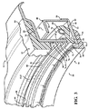
図をより詳細に参照して、図1は、発明の1つの側面に従い構成された、以下アセンブリ10と称される動的径方向シャフトシールを示す。アセンブリ10は、アセンブリの大気側Aのごみおよびその他の汚れがオイル側Oに入るのを防ぐと同時に、アセンブリのオイル側Oに、たとえばオイルのような潤滑油を保持する。アセンブリ10は、環状外側シール部品12と、環状内側シール部品14とを含む。内側シール部品14は、シャフト22周囲での受けのためにサイズ決めされたボア20と、円筒形外側転走面24とを含む円筒形内壁18を有する内側摩耗スリーブ16を含む。さらに、摩耗スリーブ16は、アセンブリ10の大気側Aの内壁18の大気端(air end)にある転走面24から径方向に外側に向かって延びる外側フランジ26を有する。外側シール部品12は、たとえば金属(たとえば、スチール)のような剛性材料で構成され、外側ケース28とも称される環状外側キャリアを含む。外側ケース28は、一般的に、ハウジング32のボア34において、たとえば圧入または他の搭載機構によりハウジング32中での固定された受けのために構成される円筒形外壁30を有する。外側ケース28は、さらに、脚部またはリム36と称され、円筒形外壁30から径方向に内側に向かって延びる環状のフランジを有する。弾性体38は、たとえば、成形されるかまたは直接そこに接着されることにより、リム36に取り付けられる。弾性体38は、摩耗スリーブ16の外側転走面24を係合するように構成される環状メインシールリップ40と、リム36から軸方向に延びている、少なくとも組立中および高いスラスト負荷状態でフランジ26と当接する、複数のスラストパッド42とを含む。スラストパッド42は、ギャップ44とも称される周方向に間隔を空けた窪みによって互いから周方向に間隔を空けられ、弾性体38は、さらに、フランジ26から軸方向に延び、スラストパッド42同士の間のギャップ44を架橋する第1のごみ除去リップ46を含む。その結果、スラストパッド42および第1のごみ除去リップ46は、互いに同じ円形の経路に沿って、または実質的にそれに沿って存在するので、径方向に小型の組み合わせ特徴を形成する。スラストパッド42は、たとえば組立中に、外側シール部品12および内側シール部品14の過度の圧縮に互いに対して軸方向に耐える。これにより、シールアセンブリ10の関連の密閉特徴が損傷しないままとなり、使用中に意図した通りに機能することが確実となる。第1のごみ除去リップ46は、ごみおよびその他の汚れがメインシールリップ40の領域に侵入することを抑制するように動作する。それゆえに、シールアセンブリ10の関連の密閉特徴が損傷しないままとなり、使用中に意図した通りに機能することがさらに確実となる。
Detailed Description of the Presently Preferred Embodiment Referring to the drawings in more detail, FIG. 1 illustrates a dynamic radial shaft seal, hereinafter referred to as an
一例としておよび限定されることなく、内側摩耗スリーブ16は、摩耗スリーブ10のオイル端から延びている環状内側フランジ48を有するように示される。内側フランジ48は、断面がほぼL型であり、軸方向に間隔を空けられ、かつ外側フランジ26に対してほぼ平行な関係にある内壁18から径方向に外側に向かって延びる直立の脚部50を有する。さらに、フランジ48は、内壁18の転走面24の上に重なる関係で裏返しに折り畳まれる円筒部52を有する。その結果、円筒部52は、内壁18の部分と径方向に整列される。フランジ48は、リップ54の上に巻かれるか、またはそうでなければ折り畳まれることによって保持されて示される。摩耗スリーブ16は、ポリマー材料56がボア20内に接合されて示される。ポリマー材料56は、シャフト22および摩耗スリーブ16が互いに協働して回転するように、シャフト22上の摩耗スリーブ16に固定された嵌合を与える。所望により、ボア20がシャフト22の外側表面に直接当接するようにサイズ決めされることで、ポリマー材料56を排除することができることを認識すべきである。
By way of example and not limitation, the inner wear sleeve 16 is shown having an annular
外側ケース28の外壁30は、環状の段差を有するように示され、そのため、外壁30のオイル側部分は、ハウジング32のボア34内にぴったりとはまるように近接した、好ましくはライントゥライン(line-to-line)にサイズ決めされる拡大直径部58を有する。一方で、外壁30の大気側部分は、外側弾性材料62を収容するために縮小直径部60に向けて径方向に内向きに段差を付けられ、たとえば、所望により弾性体38と一体の材料の単一片として、またはそれとは別々に形成することができる。外側弾性材料62は、ハウジング32のボア34内にぴったりとはまるように構成される外面64と、大気側Aに向かって軸方向に延びる環状大気側突出部66とを有する。突出部66は、外側フランジ26の端に対してわずかに径方向に間隔を空けて重なる関係で、大気側Aに向かって軸方向にリム36を超えて延び、非接触迷路状通路68をその間に形成する。
The
弾性体38は、たとえば単一のインサート成型操作により、外側弾性材料62と一体の単一片の材料として、またはそれとは別々に形成することができる。弾性体38は、摩耗スリーブ16の外側転走面24と密閉して係合するように構成され、径方向に内側に向かって延びるメインシールリップ40と、周方向に間隔を空けたスラストパッド42と、スラストパッド42同士の間のギャップ44を架橋する第1のごみ除去リップ46と、付加的な特徴とを含む。付加的な特徴は、二次ごみ除去リップ70と、三次ごみ除去リップ72と、補助シールリップ74とを含む。二次ごみ除去リップ70と、三次ごみ除去リップ72とは、径方向に、互いに同心円状の関係で間隔を空けられ、二次ごみ除去リップ70は、第1のごみ除去リップ46から径方向に内側に向かって間隔を空けられ、三次ごみ除去リップ72は、二次ごみ除去リップ70から径方向に内側に向かって間隔を空けられる。第1のごみ除去リップ46、二次ごみ除去リップ70、および三次ごみ除去リップ72の各々は、外側フランジ26に係合してアセンブリ10にごみおよびその他の汚れが侵入することを防ぐように構成される。それにより、ごみおよび汚れがメインシールリップ40に接触することを防ぐ。さらに、補助シールリップ74は、三次ごみ除去リップ72とメインシールリップ40との間に位置し、摩耗スリーブ16の外側転走面24に係合するように構成される。メインシールリップ40を外側転走面24と密閉関係に維持することを容易にするために、ガータースプリング76のようなバネ部材を使用して、転走面24に当接するように径方向に内側に向かってメインシールリップ40を付勢することができる。
The
図2に最もよく示されるように、スラストパッド42は、ギャップ44によって互いから周方向に間隔を空けられる。スラストパッド42は、ほぼ滑らかな態様で軸方向に内側に向かっておよび外側に向かって波状にうねる軸方向に面した表面によって形成され、所望の数の、例としてここでは12枚のスラストパッドを形成する。このように、大気側Aに向かって延びている波状表面のピークPは、スラストパッド42のスラスト面を形成し、一方で、リム36に向けて軸方向に内側に向けて延びそれゆえにオイル側に向けて延びる窪みVは、外側フランジ26から軸方向に間隔を空けた状態を維持するギャップ44を形成する。そのため、周方向に延びる波状表面の窪みVは、スラストパッド42を互いに連結する。ギャップ44の領域において、周方向に延びる第1のごみ除去リップ46は、大気側Aに向かって外側に軸方向に波状表面と径方向に整列するように延びて外側フランジ26に当接し、それにより、ごみおよびその他の汚れが二次ごみ除去リップ70に達することを抑制する。第1のごみ除去リップ46は、スラストパッド42の各々の径方向に最も内側の部分と結合し、こうして、パッド42のスラスト面は第1のごみ除去リップ46から径方向に外側に向かって延びる。第1のごみ除去リップ46およびスラストパッド42のスラスト面は、径方向に延びる平面Pに沿って互いに同一平面上にまたは実質的に同一平面上に形成され得る。そうでない場合、第1のごみ除去リップ46は、大気側Aに向けてスラストパッド42のスラスト面をわずかに軸方向に超えて延びるように形成され、それによって、第1のごみ除去リップ46を、スラストパッド42によって中断されない周方向に連続的なリップとして形成することができる。それゆえに、アセンブリ10を通常に使用すると、スラストパッド42は、外側フランジ26からわずかに間隔を空けた状態に留まることができ、同時に、第1のごみ除去リップ46は、周方向に連続に外側フランジ26と当接する。スラストパッド42は、たとえば組立中のような、外側シール部品12および内側シール部品14を互いに向けて付勢の片寄らせる傾向にある高いスラスト状態の間のみ外側フランジ26に接触する。そのため、スラストパッド42は、通常使用の際は、外側フランジ26から間隔を空けた状態に留まるようにされ得、それによって、摩擦を最小限にすることができる。当然ながら、スラストパッド42が第1のごみ除去リップ46と同一平面上にある場合は、スラストパッド42が周方向に不連続である結果、摩擦が低減されることが認識されるべきである。
As best shown in FIG. 2, the
図4において、発明の他の側面に従って構成されたシールアセンブリの弾性体138が示されており、100だけずれた以上で用いたのと同一の参照符号は、同様の特徴を識別するために使用される。
In FIG. 4, an
弾性体138は、弾性体38に関して以上で論じたのと本質的には同じであるが、第1のごみ除去リップ146の構成が以上で論じたものから修正されている。第1のごみ除去リップ146は、一定の円形経路に沿って延びているというよりはむしろ、周方向に曲がりくねった、または、ほぼ曲がりくねった経路にわたって波状にうねる。それゆえに、示されるように、隣接するスラストパッド142同士の間に形成されるギャップ144の領域において、第1のごみ除去リップ146は、ギャップ144の窪みVの内側で波状にうねる。その結果、第1のごみ除去リップ146は、隣接するスラストパッド142同士の間で径方向に波状にうねる。その他の点では、弾性体138は、弾性体38に関して以上で論じたのと同じであるので、さらに論じない。
The
図5において、発明の他の側面に従って構成されたシールアセンブリの弾性体238が示されており、200だけずれた以上で用いたのと同一の参照符号は、同様の特徴を識別するために使用される。
In FIG. 5, an
弾性体238は、弾性体138に関して以上で論じたのと本質的には同じであり、第1のごみ除去リップ246が、隣接するスラストパッド242同士の間に径方向に波状にうねっているが、二次ごみ除去リップ270および三次ごみ除去リップ272の構成が、一定の円形経路に沿って延びているというよりはむしろ、第1のごみ除去リップ246と同じ経路に沿って径方向に波状にうねるように修正される。それゆえに、第1のごみ除去リップ246、二次ごみ除去リップ270、および三次ごみ除去リップ272は、それらが径方向に内側に向かいおよび外側に向かって波状にうねるので、互いから、周方向に一様に間隔を空けた状態に留まる。その他の点では、弾性体238は、弾性体38,138に関して以上で論じたのと同じであるので、さらに論じない。
The
本発明の多くの変更例および変形例が、上記教示に照らして可能である。それゆえに、本発明は、具体的に説明された以外にも実施され得ること、および本発明の範囲が究極的には任意の許可された請求項によって規定されることを理解されるべきである。 Many modifications and variations of the present invention are possible in light of the above teachings. Therefore, it is to be understood that the invention can be practiced otherwise than as specifically described, and that the scope of the invention is ultimately defined by any allowed claims. .
Claims (10)
シャフトの周囲での受けのためにサイズ決めされるボアを含む円筒形内壁と、外側転走面とを有する内側摩耗スリーブを備え、前記内側摩耗スリーブは、前記内壁から径方向に外側に向かって延びるフランジを有し、前記動的径方向シャフトシールアセンブリは、さらに、
ハウジング中での受けのために構成される円筒形外壁と、前記外壁から径方向に内側に向かって延びるリムとを有する外側ケースと、
前記リムに取り付けられる弾性体とを備え、前記弾性体は、前記外側転走面に当接するメインシールリップと、前記フランジに向けて前記リムから軸方向に延びる複数のスラストパッドとを含み、前記スラストパッドは、第1の直径を有する円周に沿ってスラスト面を形成するピークを有し、前記スラストパッドの前記ピークは、軸方向に沿って形成された窪みによって互いから周方向に間隔が空けられており、前記弾性体は、さらに、前記リムから軸方向に延び、かつ前記スラストパッドの前記ピーク同士の間の前記窪みを架橋する第1のごみ除去リップを含み、前記第1のごみ除去リップは、前記第1の直径を有する円周に沿って延びる自由端を有し、
前記スラストパッドは、軸方向の両側に向かって波状にうねり周方向に延びる波状表面によって互いに周方向に連結されている、動的径方向シャフトシールアセンブリ。 A dynamic radial shaft seal assembly comprising:
An inner wear sleeve having a cylindrical inner wall including a bore sized for receiving around the shaft and an outer rolling surface, the inner wear sleeve radially outward from the inner wall The dynamic radial shaft seal assembly further comprises a flange extending;
An outer case having a cylindrical outer wall configured for receiving in the housing and a rim extending radially inwardly from the outer wall;
An elastic body attached to the rim, wherein the elastic body includes a main seal lip that contacts the outer rolling surface, and a plurality of thrust pads that extend in the axial direction from the rim toward the flange, The thrust pad has a peak that forms a thrust surface along a circumference having a first diameter, and the peaks of the thrust pad are spaced circumferentially from each other by recesses formed along an axial direction. The elastic body further includes a first dust removal lip extending in an axial direction from the rim and bridging the depression between the peaks of the thrust pad, the first dust The removal lip has a free end extending along a circumference having the first diameter;
The dynamic radial shaft seal assembly, wherein the thrust pads are circumferentially connected to each other by a corrugated surface that undulates in a circumferential direction toward both axial sides.
シャフトの周囲での受けのためにサイズ決めされるボアを含む円筒形内壁と、外側転走面とを有する内側摩耗スリーブを備え、前記内側摩耗スリーブは、前記内壁から径方向に外側に向かって延びるフランジを有し、前記動的径方向シャフトシールアセンブリは、さらに、
ハウジング中での受けのために構成される円筒形外壁と、前記外壁から径方向に内側に向かって延びるリムとを有する外側ケースと、
前記リムに取り付けられる弾性体とを備え、前記弾性体は、前記外側転走面に当接するメインシールリップと、前記フランジに向けて前記リムから軸方向に延びる複数のスラストパッドとを含み、前記スラストパッドは、第1の直径を有する円周に沿ってスラスト面を形成するピークを有し、前記スラストパッドの前記ピークは、軸方向に沿って形成された窪みによって互いから周方向に間隔が空けられており、前記弾性体は、さらに、前記リムから軸方向に延び、かつ前記スラストパッドの前記ピーク同士の間の前記窪みを架橋する第1のごみ除去リップを含み、前記第1のごみ除去リップは、前記第1の直径を有する円周に沿って延びる自由端を有し、
前記第1のごみ除去リップは、前記スラストパッド同士の間で径方向に波状にうねっている、動的径方向シャフトシールアセンブリ。 A dynamic radial shaft seal assembly comprising:
An inner wear sleeve having a cylindrical inner wall including a bore sized for receiving around the shaft and an outer rolling surface, the inner wear sleeve radially outward from the inner wall The dynamic radial shaft seal assembly further comprises a flange extending;
An outer case having a cylindrical outer wall configured for receiving in the housing and a rim extending radially inwardly from the outer wall;
An elastic body attached to the rim, wherein the elastic body includes a main seal lip that contacts the outer rolling surface, and a plurality of thrust pads that extend in the axial direction from the rim toward the flange, The thrust pad has a peak that forms a thrust surface along a circumference having a first diameter, and the peaks of the thrust pad are spaced circumferentially from each other by recesses formed along an axial direction. The elastic body further includes a first dust removal lip extending in an axial direction from the rim and bridging the depression between the peaks of the thrust pad, the first dust The removal lip has a free end extending along a circumference having the first diameter;
A dynamic radial shaft seal assembly in which the first debris removal lip undulates radially between the thrust pads.
Applications Claiming Priority (3)
| Application Number | Priority Date | Filing Date | Title |
|---|---|---|---|
| US12/886,099 US8439363B2 (en) | 2010-09-20 | 2010-09-20 | Dynamic radial shaft seal assembly with combination dust exclusion thrust pad |
| US12/886,099 | 2010-09-20 | ||
| PCT/US2011/049046 WO2012039880A1 (en) | 2010-09-20 | 2011-08-25 | Dynamic radial shaft seal assembly with combination dust exclusion thrust pad |
Publications (3)
| Publication Number | Publication Date |
|---|---|
| JP2013540965A JP2013540965A (en) | 2013-11-07 |
| JP2013540965A5 JP2013540965A5 (en) | 2014-09-18 |
| JP6027534B2 true JP6027534B2 (en) | 2016-11-16 |
Family
ID=44534720
Family Applications (1)
| Application Number | Title | Priority Date | Filing Date |
|---|---|---|---|
| JP2013529165A Expired - Fee Related JP6027534B2 (en) | 2010-09-20 | 2011-08-25 | Dynamic radial shaft seal assembly with combined dust removal thrust pad |
Country Status (7)
| Country | Link |
|---|---|
| US (1) | US8439363B2 (en) |
| EP (1) | EP2619487B1 (en) |
| JP (1) | JP6027534B2 (en) |
| KR (1) | KR101852890B1 (en) |
| CN (1) | CN103228963B (en) |
| BR (1) | BR112013006637A2 (en) |
| WO (1) | WO2012039880A1 (en) |
Families Citing this family (14)
| Publication number | Priority date | Publication date | Assignee | Title |
|---|---|---|---|---|
| US8657296B1 (en) | 2011-10-26 | 2014-02-25 | Engineered Seal Products, Inc. | Radial shaft seal |
| DE202015106914U1 (en) | 2015-12-17 | 2016-01-20 | Danfoss Power Electronics A/S | Sealing device for a driven axle and seal carrier for a sealing device |
| FR3047533B1 (en) * | 2016-02-09 | 2018-07-13 | Carl Freudenberg Kg | IMPROVED SEALING DEVICE, IN PARTICULAR WITH RESPECT TO CONTAMINATION BY EXTERNAL AGENTS |
| CN105952875B (en) * | 2016-07-06 | 2018-09-14 | 中国神华能源股份有限公司 | For the rotary packing ring of gear-box and the sealing structure of gear-box |
| IT201600113594A1 (en) * | 2016-11-10 | 2018-05-10 | Freudenberg Sealing Tech S A S Di Externa Italia S R L U | SEALING GROUP FOR A ROTATING ORGAN |
| TWI603860B (en) * | 2017-02-24 | 2017-11-01 | Wheel seal | |
| US10550941B2 (en) * | 2017-07-03 | 2020-02-04 | Aktiebolaget Skf | Radial fluid seal |
| JP2018063050A (en) * | 2017-12-14 | 2018-04-19 | 光洋シーリングテクノ株式会社 | Seal member |
| DE102019204877A1 (en) * | 2018-04-06 | 2019-10-10 | Nabtesco Corporation | Sealing structure and this seal structure having device |
| CN111853243A (en) * | 2019-04-29 | 2020-10-30 | 舍弗勒技术股份两合公司 | Sealing element |
| WO2020250579A1 (en) * | 2019-06-12 | 2020-12-17 | Nok株式会社 | Sealing device |
| US11371612B2 (en) * | 2020-05-07 | 2022-06-28 | Aktiebolaget Skf | Sleeve for a seal assembly |
| US20220216763A1 (en) * | 2021-01-05 | 2022-07-07 | Fairway Electronic Co., Ltd. | Rotating Machine |
| CN115111367A (en) * | 2021-03-23 | 2022-09-27 | 斯凯孚公司 | Sealing assembly and use thereof |
Family Cites Families (28)
| Publication number | Priority date | Publication date | Assignee | Title |
|---|---|---|---|---|
| US3156474A (en) | 1961-06-19 | 1964-11-10 | Chicago Rawhide Mfg Co | Self-contained oil seal assembly |
| CH506300A (en) | 1969-02-20 | 1971-04-30 | Schmid Hans | ski |
| US4037849A (en) | 1976-02-11 | 1977-07-26 | The Mechanex Corporation | Lubricant seal |
| US4208057A (en) | 1976-03-08 | 1980-06-17 | Garlock Inc. | Semi-unitized shaft seal and method |
| US4226426A (en) * | 1979-02-26 | 1980-10-07 | Garlock Inc. | Semi-unitized shaft seal |
| US5004248A (en) | 1983-08-25 | 1991-04-02 | Garlock Inc. | Unitized seal with unitizing joint remote from seal lip |
| JPH0135982Y2 (en) * | 1985-05-08 | 1989-11-01 | ||
| JPH0645099Y2 (en) * | 1988-02-24 | 1994-11-16 | エヌオーケー株式会社 | Sealing device |
| JPH0495671A (en) * | 1990-08-13 | 1992-03-27 | Kubota Corp | Oil sealing device for engine rotation shaft |
| US5183269A (en) | 1991-02-06 | 1993-02-02 | Chicago Rawhide Manufacturing Co. | Unitized grit seal with removable thrust bumper |
| DE4110154C2 (en) | 1991-03-27 | 1996-08-29 | Bruss Dichtungstechnik | Shaft seal |
| JPH0710630U (en) * | 1993-07-16 | 1995-02-14 | エヌオーケー株式会社 | Sealing device |
| US20020011710A1 (en) | 1997-09-25 | 2002-01-31 | Oldenburg Michael R. | Retrofittable severe duty seal for a shaft |
| US6186507B1 (en) | 1997-09-25 | 2001-02-13 | Michael R. Oldenburg | Retrofittable severe duty seal for a shaft |
| US6464228B1 (en) | 1997-09-25 | 2002-10-15 | Transcom, Incorporated | Method of using a retrofittable severe duty seal for a shaft |
| US6315296B1 (en) | 1997-09-25 | 2001-11-13 | Transcom, Inc. | Flangeless retrofittable severe duty seal for a shaft |
| US5997005A (en) | 1997-10-24 | 1999-12-07 | Stemco Inc | Hub seal with machinable thrust ring |
| US6170833B1 (en) | 1997-10-24 | 2001-01-09 | Stemco Inc | Hub seal with machinable thrust ring and lay-down sealing lip |
| US6257587B1 (en) | 1999-05-21 | 2001-07-10 | Federal-Mogul World Wide, Inc. | Radial lip seal having protected porous dust excluder |
| ITMI991135A1 (en) * | 1999-05-24 | 2000-11-24 | Rolf S P A | BOX-TYPE SEALING COMPLEX IN PARTICULAR FOR VEHICLE AXLES |
| US6406029B1 (en) | 1999-08-17 | 2002-06-18 | Caterpillar Inc. | Seal assembly having an encapsulated cone spring |
| US6193264B1 (en) * | 1999-09-03 | 2001-02-27 | Park Do Seon | Collapsible golf trolley |
| JP2007107674A (en) * | 2005-10-17 | 2007-04-26 | Uchiyama Mfg Corp | Sealing device |
| US8016293B2 (en) | 2006-01-03 | 2011-09-13 | Freudenberg-Nok General Partnership | Contaminant exclusion seal |
| US7455459B2 (en) * | 2006-03-09 | 2008-11-25 | Federal Mogul World Wide, Inc. | Oil bath encoder seal |
| US20070290451A1 (en) | 2006-06-16 | 2007-12-20 | Yager Paul E | Seal for rotating assembly |
| US7594664B2 (en) | 2006-08-29 | 2009-09-29 | Skf Usa Inc. | Seal with pyramid shaped formation |
| JP2012122534A (en) | 2010-12-08 | 2012-06-28 | Nok Corp | Sealing device |
-
2010
- 2010-09-20 US US12/886,099 patent/US8439363B2/en active Active
-
2011
- 2011-08-25 WO PCT/US2011/049046 patent/WO2012039880A1/en active Application Filing
- 2011-08-25 BR BR112013006637A patent/BR112013006637A2/en not_active IP Right Cessation
- 2011-08-25 EP EP11750060.3A patent/EP2619487B1/en not_active Not-in-force
- 2011-08-25 CN CN201180055508.6A patent/CN103228963B/en not_active Expired - Fee Related
- 2011-08-25 KR KR1020137009484A patent/KR101852890B1/en active IP Right Grant
- 2011-08-25 JP JP2013529165A patent/JP6027534B2/en not_active Expired - Fee Related
Also Published As
| Publication number | Publication date |
|---|---|
| BR112013006637A2 (en) | 2016-06-28 |
| EP2619487B1 (en) | 2015-07-15 |
| KR20140015261A (en) | 2014-02-06 |
| WO2012039880A1 (en) | 2012-03-29 |
| CN103228963A (en) | 2013-07-31 |
| US8439363B2 (en) | 2013-05-14 |
| US20120068416A1 (en) | 2012-03-22 |
| CN103228963B (en) | 2016-04-20 |
| KR101852890B1 (en) | 2018-04-30 |
| EP2619487A1 (en) | 2013-07-31 |
| JP2013540965A (en) | 2013-11-07 |
Similar Documents
| Publication | Publication Date | Title |
|---|---|---|
| JP6027534B2 (en) | Dynamic radial shaft seal assembly with combined dust removal thrust pad | |
| JP4822537B2 (en) | Sealing device | |
| US5522600A (en) | Annular lubricant seal assembly with spring member | |
| US8753017B2 (en) | Sealing device and rolling bearing unit | |
| US9163730B2 (en) | Unitized radial fluid seal | |
| JP6043304B2 (en) | Low torque radial shaft seal assembly | |
| US20120045155A1 (en) | sealed hub-bearing assembly for agricultural applications | |
| JP2005351392A (en) | Sealing device | |
| US9958011B2 (en) | Bearing assembly having surface protrusions and a seal | |
| JP2006342829A (en) | Sealing device | |
| US9869393B2 (en) | Shaft seal, especially radial shaft seal | |
| US20040227303A1 (en) | Cassette seal | |
| JP2008232404A (en) | Vehicular hub unit | |
| JP6426828B2 (en) | Sealing device | |
| JP5224049B2 (en) | Oil seal | |
| JP4417190B2 (en) | Sealing device | |
| JP2023030822A (en) | Rolling bearing and rolling bearing unit | |
| JP2010249168A (en) | Sealing device | |
| JP2003106463A (en) | Hermetically sealed device | |
| CN113606341A (en) | Sealing device | |
| JP2011144868A (en) | Clutch release bearing | |
| JP2021025532A (en) | Sealing device | |
| JP2006105189A (en) | Sealing device | |
| JP2019078318A (en) | Sealing device | |
| JP2007218366A (en) | Seal with shaft |
Legal Events
| Date | Code | Title | Description |
|---|---|---|---|
| A621 | Written request for application examination |
Free format text: JAPANESE INTERMEDIATE CODE: A621 Effective date: 20140311 |
|
| A521 | Written amendment |
Free format text: JAPANESE INTERMEDIATE CODE: A523 Effective date: 20140730 |
|
| A977 | Report on retrieval |
Free format text: JAPANESE INTERMEDIATE CODE: A971007 Effective date: 20150115 |
|
| A131 | Notification of reasons for refusal |
Free format text: JAPANESE INTERMEDIATE CODE: A131 Effective date: 20150224 |
|
| A601 | Written request for extension of time |
Free format text: JAPANESE INTERMEDIATE CODE: A601 Effective date: 20150522 |
|
| A521 | Written amendment |
Free format text: JAPANESE INTERMEDIATE CODE: A523 Effective date: 20150624 |
|
| A02 | Decision of refusal |
Free format text: JAPANESE INTERMEDIATE CODE: A02 Effective date: 20151117 |
|
| A521 | Written amendment |
Free format text: JAPANESE INTERMEDIATE CODE: A523 Effective date: 20160317 |
|
| A521 | Written amendment |
Free format text: JAPANESE INTERMEDIATE CODE: A821 Effective date: 20160317 |
|
| A911 | Transfer of reconsideration by examiner before appeal (zenchi) |
Free format text: JAPANESE INTERMEDIATE CODE: A911 Effective date: 20160411 |
|
| A131 | Notification of reasons for refusal |
Free format text: JAPANESE INTERMEDIATE CODE: A131 Effective date: 20160628 |
|
| A521 | Written amendment |
Free format text: JAPANESE INTERMEDIATE CODE: A523 Effective date: 20160914 |
|
| TRDD | Decision of grant or rejection written | ||
| A01 | Written decision to grant a patent or to grant a registration (utility model) |
Free format text: JAPANESE INTERMEDIATE CODE: A01 Effective date: 20161004 |
|
| A61 | First payment of annual fees (during grant procedure) |
Free format text: JAPANESE INTERMEDIATE CODE: A61 Effective date: 20161014 |
|
| R150 | Certificate of patent or registration of utility model |
Ref document number: 6027534 Country of ref document: JP Free format text: JAPANESE INTERMEDIATE CODE: R150 |
|
| R250 | Receipt of annual fees |
Free format text: JAPANESE INTERMEDIATE CODE: R250 |
|
| LAPS | Cancellation because of no payment of annual fees |