JP6025587B2 - Combustor and gas turbine - Google Patents
Combustor and gas turbine Download PDFInfo
- Publication number
- JP6025587B2 JP6025587B2 JP2013018481A JP2013018481A JP6025587B2 JP 6025587 B2 JP6025587 B2 JP 6025587B2 JP 2013018481 A JP2013018481 A JP 2013018481A JP 2013018481 A JP2013018481 A JP 2013018481A JP 6025587 B2 JP6025587 B2 JP 6025587B2
- Authority
- JP
- Japan
- Prior art keywords
- communication hole
- extension pipe
- main
- corner
- combustor
- Prior art date
- Legal status (The legal status is an assumption and is not a legal conclusion. Google has not performed a legal analysis and makes no representation as to the accuracy of the status listed.)
- Active
Links
Images


Classifications
-
- F—MECHANICAL ENGINEERING; LIGHTING; HEATING; WEAPONS; BLASTING
- F23—COMBUSTION APPARATUS; COMBUSTION PROCESSES
- F23R—GENERATING COMBUSTION PRODUCTS OF HIGH PRESSURE OR HIGH VELOCITY, e.g. GAS-TURBINE COMBUSTION CHAMBERS
- F23R3/00—Continuous combustion chambers using liquid or gaseous fuel
- F23R3/02—Continuous combustion chambers using liquid or gaseous fuel characterised by the air-flow or gas-flow configuration
- F23R3/16—Continuous combustion chambers using liquid or gaseous fuel characterised by the air-flow or gas-flow configuration with devices inside the flame tube or the combustion chamber to influence the air or gas flow
- F23R3/18—Flame stabilising means, e.g. flame holders for after-burners of jet-propulsion plants
-
- F—MECHANICAL ENGINEERING; LIGHTING; HEATING; WEAPONS; BLASTING
- F23—COMBUSTION APPARATUS; COMBUSTION PROCESSES
- F23R—GENERATING COMBUSTION PRODUCTS OF HIGH PRESSURE OR HIGH VELOCITY, e.g. GAS-TURBINE COMBUSTION CHAMBERS
- F23R3/00—Continuous combustion chambers using liquid or gaseous fuel
- F23R3/02—Continuous combustion chambers using liquid or gaseous fuel characterised by the air-flow or gas-flow configuration
- F23R3/04—Air inlet arrangements
- F23R3/10—Air inlet arrangements for primary air
-
- F—MECHANICAL ENGINEERING; LIGHTING; HEATING; WEAPONS; BLASTING
- F23—COMBUSTION APPARATUS; COMBUSTION PROCESSES
- F23R—GENERATING COMBUSTION PRODUCTS OF HIGH PRESSURE OR HIGH VELOCITY, e.g. GAS-TURBINE COMBUSTION CHAMBERS
- F23R3/00—Continuous combustion chambers using liquid or gaseous fuel
- F23R3/02—Continuous combustion chambers using liquid or gaseous fuel characterised by the air-flow or gas-flow configuration
- F23R3/16—Continuous combustion chambers using liquid or gaseous fuel characterised by the air-flow or gas-flow configuration with devices inside the flame tube or the combustion chamber to influence the air or gas flow
-
- F—MECHANICAL ENGINEERING; LIGHTING; HEATING; WEAPONS; BLASTING
- F23—COMBUSTION APPARATUS; COMBUSTION PROCESSES
- F23R—GENERATING COMBUSTION PRODUCTS OF HIGH PRESSURE OR HIGH VELOCITY, e.g. GAS-TURBINE COMBUSTION CHAMBERS
- F23R3/00—Continuous combustion chambers using liquid or gaseous fuel
- F23R3/28—Continuous combustion chambers using liquid or gaseous fuel characterised by the fuel supply
- F23R3/286—Continuous combustion chambers using liquid or gaseous fuel characterised by the fuel supply having fuel-air premixing devices
-
- F—MECHANICAL ENGINEERING; LIGHTING; HEATING; WEAPONS; BLASTING
- F23—COMBUSTION APPARATUS; COMBUSTION PROCESSES
- F23R—GENERATING COMBUSTION PRODUCTS OF HIGH PRESSURE OR HIGH VELOCITY, e.g. GAS-TURBINE COMBUSTION CHAMBERS
- F23R3/00—Continuous combustion chambers using liquid or gaseous fuel
- F23R3/28—Continuous combustion chambers using liquid or gaseous fuel characterised by the fuel supply
- F23R3/34—Feeding into different combustion zones
- F23R3/343—Pilot flames, i.e. fuel nozzles or injectors using only a very small proportion of the total fuel to insure continuous combustion
-
- F—MECHANICAL ENGINEERING; LIGHTING; HEATING; WEAPONS; BLASTING
- F23—COMBUSTION APPARATUS; COMBUSTION PROCESSES
- F23R—GENERATING COMBUSTION PRODUCTS OF HIGH PRESSURE OR HIGH VELOCITY, e.g. GAS-TURBINE COMBUSTION CHAMBERS
- F23R3/00—Continuous combustion chambers using liquid or gaseous fuel
- F23R3/42—Continuous combustion chambers using liquid or gaseous fuel characterised by the arrangement or form of the flame tubes or combustion chambers
- F23R3/46—Combustion chambers comprising an annular arrangement of several essentially tubular flame tubes within a common annular casing or within individual casings
-
- F—MECHANICAL ENGINEERING; LIGHTING; HEATING; WEAPONS; BLASTING
- F23—COMBUSTION APPARATUS; COMBUSTION PROCESSES
- F23R—GENERATING COMBUSTION PRODUCTS OF HIGH PRESSURE OR HIGH VELOCITY, e.g. GAS-TURBINE COMBUSTION CHAMBERS
- F23R2900/00—Special features of, or arrangements for continuous combustion chambers; Combustion processes therefor
- F23R2900/03343—Pilot burners operating in premixed mode
-
- F—MECHANICAL ENGINEERING; LIGHTING; HEATING; WEAPONS; BLASTING
- F23—COMBUSTION APPARATUS; COMBUSTION PROCESSES
- F23R—GENERATING COMBUSTION PRODUCTS OF HIGH PRESSURE OR HIGH VELOCITY, e.g. GAS-TURBINE COMBUSTION CHAMBERS
- F23R3/00—Continuous combustion chambers using liquid or gaseous fuel
- F23R3/02—Continuous combustion chambers using liquid or gaseous fuel characterised by the air-flow or gas-flow configuration
- F23R3/04—Air inlet arrangements
- F23R3/10—Air inlet arrangements for primary air
- F23R3/12—Air inlet arrangements for primary air inducing a vortex
- F23R3/14—Air inlet arrangements for primary air inducing a vortex by using swirl vanes
Landscapes
- Engineering & Computer Science (AREA)
- Chemical & Material Sciences (AREA)
- Combustion & Propulsion (AREA)
- Mechanical Engineering (AREA)
- General Engineering & Computer Science (AREA)
- Gas Burners (AREA)
- Pre-Mixing And Non-Premixing Gas Burner (AREA)
Description
本発明は、予混合燃焼を行うバーナ(メインバーナ)を有する燃焼器および当該燃焼器が適用されるガスタービンに関する。 The present invention relates to a combustor having a burner (main burner) that performs premixed combustion, and a gas turbine to which the combustor is applied.
例えば、特許文献1には、予混合方式を採用する燃焼器が示されている。この燃焼器は、予混合燃焼を行うメインバーナに加え、予混合燃焼を安定に維持するために拡散燃焼を行うパイロットバーナが設けられている。パイロットバーナによって生成される拡散炎が、メインバーナが予混合炎を生成するための種火として使用され、これによって予混合燃焼が維持される。一般的な燃焼器では、メインバーナは、パイロットバーナを中心とした半径方向外側に周方向に等間隔で配置される。 For example, Patent Document 1 discloses a combustor that employs a premixing system. This combustor is provided with a pilot burner that performs diffusion combustion in order to stably maintain the premix combustion in addition to the main burner that performs premix combustion. The diffusion flame generated by the pilot burner is used as a pilot for the main burner to generate the premixed flame, thereby maintaining the premixed combustion. In a general combustor, the main burners are arranged at equal intervals in the circumferential direction on the outer side in the radial direction around the pilot burner.
メインバーナは、円筒形のバーナ外筒(メインバーナ筒)内に、メインノズルおよびメインスワラを備えている。バーナ外筒は、その先端に延長管が接続されている。そして、メインバーナは、その内部で燃料と空気とを混合して予混合気を生成し、生成された予混合気を延長管の先端から噴出する。より詳細には、メインスワラの上流において、圧縮機(図示せず)から供給される圧縮空気に対してメインノズルによって燃料を噴射し、メインスワラによって空気および燃料の流れを旋回させる。これにより、空気と燃料とが混合された予混合気が生成されるとともに、予混合気の旋回流(スワール流れ)が発生する。そして、予混合気は、延長管から噴出され、さらに、パイロットバーナにより生成された拡散炎を用いて延長管の下流側で燃焼され、これにより、予混合燃焼が実現される。 The main burner includes a main nozzle and a main swirler in a cylindrical burner outer cylinder (main burner cylinder). An extension pipe is connected to the tip of the burner outer cylinder. The main burner mixes fuel and air inside to generate a premixed gas, and ejects the generated premixed gas from the tip of the extension pipe. More specifically, upstream of the main swirler, fuel is injected by the main nozzle into compressed air supplied from a compressor (not shown), and the flow of air and fuel is swirled by the main swirler. Thus, a premixed gas in which air and fuel are mixed is generated, and a swirling flow (swirl flow) of the premixed gas is generated. Then, the premixed gas is ejected from the extension pipe and further burned on the downstream side of the extension pipe using the diffusion flame generated by the pilot burner, thereby realizing premix combustion.
ところで、延長管の内壁面近傍は低流速となるため、メインバーナの逆火(フラッシュバック)が発生しやすい。フラッシュバックの発生は燃焼器の焼損を招くため、フラッシュバックは、可能な限り抑えられなくてはならない。特許文献1においては、このフラッシュバックを防止するために、延長管の形状を工夫したり、バーナ外筒と延長管との接続部から膜状の空気(フィルム空気)を取り入れたりすることが示されている。延長管の形状としては、入口がバーナ外筒に合わせて円形状であり、出口が、2つの半径方向エッジと、各半径方向エッジを連結する半径方向内側および半径方向外側の各周方向エッジとで台形状に形成されている。 By the way, since the vicinity of the inner wall surface of the extension pipe has a low flow velocity, backburning (flashback) of the main burner is likely to occur. Since the occurrence of flashback leads to burnout of the combustor, the flashback must be suppressed as much as possible. Patent Document 1 shows that in order to prevent this flashback, the shape of the extension pipe is devised, or film-like air (film air) is taken in from the connecting portion between the burner outer cylinder and the extension pipe. Has been. As the shape of the extension pipe, the inlet has a circular shape corresponding to the burner outer cylinder, the outlet has two radial edges, and radially inner and radially outer circumferential edges connecting the radial edges. It is formed in a trapezoid shape.
上述した特許文献1のように、延長管の出口を台形状とし、フィルム空気を取り入れることでフラッシュバックを防止することが可能である。しかし、延長管は、入口が円形状で出口を台形状に変形させたものであり、延長管の出口において流速が高い部分と低い部分とが生じる。このため、取り入れたフィルム空気に偏りが発生するおそれがある。しかも、延長管の出口において流速が低い部分にフラッシュバックが発生しやすいことから、特にこの部分にフィルム空気を取り入れることが望まれている。 As in Patent Document 1 described above, it is possible to prevent flashback by making the outlet of the extension pipe trapezoidal and taking in film air. However, the extension pipe has a circular inlet and an outlet deformed into a trapezoid, and a portion with a high flow rate and a portion with a low flow velocity are generated at the outlet of the extension pipe. For this reason, there is a possibility that the taken-in film air may be biased. In addition, since flashback is likely to occur at a portion where the flow velocity is low at the outlet of the extension pipe, it is particularly desirable to incorporate film air into this portion.
本発明は上述した課題を解決するものであり、フラッシュバックの発生を抑制しつつ、フィルム空気の偏りを抑制することのできる燃焼器およびガスタービンを提供することを目的とする。 This invention solves the subject mentioned above, and it aims at providing the combustor and gas turbine which can suppress the bias | inclination of film air, suppressing generation | occurrence | production of flashback.
上述の目的を達成するために、第1の発明の燃焼器は、パイロットバーナと、前記パイロットバーナを中心とした半径方向外側に周方向に沿って複数設けられて、メインバーナ筒内にメインノズルが配置されたメインバーナと、各前記メインバーナの前記メインバーナ筒から下流側に延在して設けられており、前記メインバーナ筒に繋がる入口が円形状で、下流側の出口が半径方向に平行な2つの半径方向エッジ、および各前記半径方向エッジの両端を連結するように周方向に沿う2つの周方向エッジで形成された延長管と、前記メインバーナ筒の外側に設けられた空気通路と、前記延長管の入口側であって前記半径方向の内側の周方向エッジに対応する位置に設けられ前記空気通路と前記延長管内とを連通する内側連通穴と、を備えることを特徴とする。 In order to achieve the above object, a combustor according to a first aspect of the present invention is provided with a pilot burner and a plurality of circumferentially extending radially outwards centered on the pilot burner, and a main nozzle in a main burner cylinder The main burner is arranged to extend downstream from the main burner cylinder of each main burner, the inlet connected to the main burner cylinder is circular, and the downstream outlet is in the radial direction. Two parallel radial edges and an extension pipe formed by two circumferential edges along the circumferential direction so as to connect both ends of each radial edge, and an air passage provided outside the main burner cylinder And an inner communication hole provided at a position corresponding to the radially inner circumferential edge on the inlet side of the extension pipe and communicating the air passage and the extension pipe. And features.
この燃焼器によれば、内側連通穴を設けることにより、空気通路から内側連通穴を介してメインバーナ筒に空気が導入され、フィルム状の空気となってメインバーナ筒および延長管の内壁面に沿って下流側に流れる。このフィルム状の空気は、壁面近傍の低流速領域の燃料濃度を低減する。このため、フラッシュバックの発生を抑制することができる。特に、半径方向内側の周方向エッジは、パイロットバーナからの火炎に近くフラッシュバックの影響が大きい部分であるため、この部分に対応してフィルム状の空気を供給することで、フラッシュバックの発生を抑制しつつ、フィルム状の空気の偏りを抑制することができる。 According to this combustor, by providing the inner communication hole, air is introduced into the main burner cylinder from the air passage through the inner communication hole, and becomes film-like air on the inner wall surfaces of the main burner cylinder and the extension pipe. Along the downstream. This film-like air reduces the fuel concentration in the low flow velocity region near the wall surface. For this reason, generation | occurrence | production of flashback can be suppressed. In particular, the circumferential edge on the radially inner side is a part that is close to the flame from the pilot burner and has a large effect of flashback. By supplying film-like air corresponding to this part, the occurrence of flashback is prevented. While suppressing, it is possible to suppress the bias of the film-like air.
また、第2の発明の燃焼器は、第1の発明において、前記延長管の入口側であって、前記内側連通穴の位置を除き、少なくとも前記半径方向の外側の周方向エッジと前記半径方向エッジとが連通する角部に対応する位置に設けられ前記空気通路と前記延長管内とを連通する角部連通穴をさらに備えることを特徴とする。 The combustor according to a second aspect of the present invention is the combustor according to the first aspect of the present invention, which is on the inlet side of the extension pipe and excluding the position of the inner communication hole, at least the outer circumferential edge in the radial direction and the radial direction. It is further provided with a corner communication hole provided at a position corresponding to a corner communicating with the edge and communicating the air passage and the inside of the extension pipe.
この燃焼器によれば、周方向エッジと半径方向エッジとが連通する角部は、円形状の入口から半径方向に広がって流体を拡散させ流速が特に低くなりやすい部分であり、この角部に対応する内側連通穴を設けることにより、フラッシュバックの発生を抑制しつつ、フィルム状の空気の偏りを抑制する効果を顕著に得ることができる。 According to this combustor, the corner part where the circumferential edge and the radial edge communicate with each other is a part that spreads in the radial direction from the circular inlet and diffuses the fluid, and the flow velocity is particularly low. By providing the corresponding inner communication hole, the effect of suppressing the unevenness of the film-like air can be obtained while suppressing the occurrence of flashback.
また、第3の発明の燃焼器は、第2の発明において、前記内側連通穴が周方向に連続して形成され、前記角部連通穴が前記半径方向の外側の周方向エッジと前記半径方向エッジとが連通する角部に対応する位置で周方向に連続して形成されていることを特徴とする。 The combustor according to a third aspect is the combustor according to the second aspect, wherein the inner communication hole is formed continuously in the circumferential direction, and the corner communication hole is formed on the outer circumferential edge of the radial direction and the radial direction. It is characterized by being continuously formed in the circumferential direction at a position corresponding to a corner portion communicating with the edge.
この燃焼器によれば、速度が低い部分に対応してフィルム状の空気を供給するため、フラッシュバックの発生を抑制しつつ、フィルム状の空気の偏りを抑制する効果を顕著に得ることができる。 According to this combustor, since film-like air is supplied corresponding to the low-speed part, the effect of suppressing the unevenness of the film-like air can be significantly obtained while suppressing the occurrence of flashback. .
また、第4の発明の燃焼器は、第3の発明において、前記内側連通穴が前記角部連通穴よりも開口面積を大きく形成されていることを特徴とする。 The combustor according to a fourth aspect is characterized in that, in the third aspect, the inner communication hole is formed to have a larger opening area than the corner communication hole.
この燃焼器によれば、半径方向内側の周方向エッジは、パイロットバーナからの火炎に近くフラッシュバックの影響が大きい部分であるため、フラッシュバックの発生を抑制する効果を顕著に得るため、内側連通穴が角部連通穴よりも開口面積を大きく形成されていることが好ましい。 According to this combustor, the circumferential edge on the inner side in the radial direction is a portion that is close to the flame from the pilot burner and has a large influence on the flashback. It is preferable that the hole has a larger opening area than the corner communication hole.
また、第5の発明の燃焼器は、第2の発明において、前記内側連通穴が周方向に連続して形成され、前記角部連通穴が周方向で断続して形成されていることを特徴とする。 The combustor according to a fifth aspect is characterized in that, in the second aspect, the inner communication hole is formed continuously in the circumferential direction, and the corner communication hole is formed intermittently in the circumferential direction. And
この燃焼器によれば、角部連通穴が、内側連通穴を除く範囲で断続して形成されているため、パイロットバーナからの火炎に近くフラッシュバックの影響が大きい部分である半径方向内側の周方向エッジに対応する内側連通穴側に比較的多くの空気を供給することができる。 According to this combustor, since the corner communication holes are formed intermittently in a range excluding the inner communication holes, the inner periphery in the radial direction, which is close to the flame from the pilot burner and has a large influence of flashback, is formed. A relatively large amount of air can be supplied to the inner communication hole side corresponding to the direction edge.
また、第6の発明の燃焼器は、パイロットバーナと、前記パイロットバーナを中心とした半径方向外側に周方向に沿って複数設けられて、メインバーナ筒内にメインノズルが配置されたメインバーナと、各前記メインバーナの前記メインバーナ筒から下流側に延在して設けられており、前記メインバーナ筒に繋がる入口が円形状で、下流側の出口が半径方向に平行な2つの半径方向エッジ、および各前記半径方向エッジの両端を連結するように周方向に沿う2つの周方向エッジで形成された延長管と、前記メインバーナ筒の外側に設けられた空気通路と、前記延長管の入口側であって前記半径方向の外側の周方向エッジと前記半径方向エッジとが連通する角部に対応する位置に設けられ前記空気通路と前記延長管内とを連通する角部連通穴と、を備えることを特徴とする。 A combustor according to a sixth aspect of the present invention includes a pilot burner, a main burner that is provided in a plurality along the circumferential direction on the radially outer side centering on the pilot burner, and in which a main nozzle is disposed in a main burner cylinder. Each of the main burners is provided to extend downstream from the main burner cylinder, the inlet connected to the main burner cylinder has a circular shape, and the downstream outlet has two radial edges parallel to the radial direction. And an extension pipe formed by two circumferential edges along the circumferential direction so as to connect both ends of each of the radial edges, an air passage provided outside the main burner cylinder, and an inlet of the extension pipe A corner communication hole provided at a position corresponding to a corner where the circumferential edge on the outer side in the radial direction and the radial edge communicate with each other, and communicates the air passage and the inside of the extension pipe; Characterized in that it comprises a.
この燃焼器によれば、周方向エッジと半径方向エッジとが連通する角部は、円形状の入口から半径方向に広がって流体を拡散させ流速が特に低くなりやすい部分であり、この角部に対応する内側連通穴を設けることにより、フラッシュバックの発生を抑制しつつ、フィルム状の空気の偏りを抑制する効果を顕著に得ることができる。 According to this combustor, the corner part where the circumferential edge and the radial edge communicate with each other is a part that spreads in the radial direction from the circular inlet and diffuses the fluid, and the flow velocity is particularly low. By providing the corresponding inner communication hole, the effect of suppressing the unevenness of the film-like air can be obtained while suppressing the occurrence of flashback.
また、第7の発明の燃焼器は、第1〜第6のいずれか1つの発明において、前記メインバーナ筒内で半径方向に延在して設けられた複数のメインスワラを有し、前記メインスワラの下流端に対応する位置に設けられて前記空気通路と前記メインバーナ筒内とを連通する翼部連通穴をさらに備えることを特徴とする。 A combustor according to a seventh invention includes a plurality of main swirlers extending in a radial direction in the main burner cylinder according to any one of the first to sixth inventions, A wing portion communication hole provided at a position corresponding to the downstream end and communicating the air passage and the inside of the main burner cylinder is further provided.
メインスワラの上流側は、流速が低くなりやすく燃料濃度が高い傾向となる。従って、メインスワラの下流端に対応する位置に翼部連通穴を設けることで、この翼部連通穴からメインバーナ筒に導入された空気により、フラッシュバックの火炎を堰き止めることができる。 On the upstream side of the main swirler, the flow rate tends to be low and the fuel concentration tends to be high. Therefore, by providing the blade communication hole at a position corresponding to the downstream end of the main swirler, the flashback flame can be blocked by the air introduced from the blade communication hole into the main burner cylinder.
上述の目的を達成するために、本発明のガスタービンは、圧縮機と、燃焼器と、タービンとを備えるガスタービンにおいて、第1〜第6のいずれか1つの発明に記載の燃焼器が適用されることを特徴とする。 In order to achieve the above object, a gas turbine according to the present invention is a gas turbine including a compressor, a combustor, and a turbine, and the combustor according to any one of the first to sixth inventions is applied. It is characterized by being.
このガスタービンによれば、フラッシュバックの抑制により燃焼器の損傷を防ぐことで、タービン性能を維持することができる。 According to this gas turbine, turbine performance can be maintained by preventing damage to the combustor by suppressing flashback.
本発明によれば、フラッシュバックの発生を抑制しつつ、フィルム空気の偏りを抑制することができる。 According to the present invention, it is possible to suppress the unevenness of the film air while suppressing the occurrence of flashback.
以下に、本発明に係る実施形態を図面に基づいて詳細に説明する。なお、この実施形態によりこの発明が限定されるものではない。また、下記実施形態における構成要素には、当業者が置換可能かつ容易なもの、あるいは実質的に同一のものが含まれる。 Embodiments according to the present invention will be described below in detail with reference to the drawings. In addition, this invention is not limited by this embodiment. In addition, constituent elements in the following embodiments include those that can be easily replaced by those skilled in the art or those that are substantially the same.
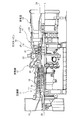
図1は、本実施形態に係る燃焼器を有するガスタービンの概略構成図である。図1に示すように、ガスタービン10は、流体の流れ方向の上流側から順番に、圧縮機11と、燃焼器12と、タービン13と、排気室14とを有する。タービン13には、図示しない発電機が連結されている。ガスタービンは、回転軸Lを中心に回転可能なロータ24を有する。
FIG. 1 is a schematic configuration diagram of a gas turbine having a combustor according to the present embodiment. As shown in FIG. 1, the
圧縮機11は、空気を取り込む空気取入口15を有し、圧縮機車室16内に複数の静翼17と動翼18とが交互に設けられている。燃焼器12は、圧縮機11で圧縮された圧縮空気(燃焼用空気)に対して燃料を供給し、バーナで点火することで燃焼可能となっている。タービン13は、タービン車室20内に複数の静翼21と動翼22とが交互に設けられている。排気室14は、タービン13に連続する排気ディフューザ23を有している。ロータ24は、圧縮機11、燃焼器12、タービン13、排気室14の径方向中心部を貫通するように位置する。ロータ24は、圧縮機11側の端部が軸受部25により支持され、排気室14側の端部が軸受部26により支持されて回転軸Lを中心にして回転自在に設けられている。ロータ24は、複数のディスクプレートが固定され、各動翼18,22が連結されている。また、ロータ24は、圧縮機11側の端部に、図示しない発電機の駆動軸が連結されている。
The
このようなガスタービンにおいて、圧縮機11の空気取入口15から取り込まれた空気は、複数の静翼17と動翼18とを通過して圧縮され、高温・高圧の圧縮空気となる。この圧縮空気は、燃焼器12において、圧縮空気に対して所定の燃料が供給されることで燃焼する。燃焼器12で生成された作動流体である高温・高圧の燃焼ガスは、タービン13を構成する複数の静翼21と動翼22とを通過し、ロータ24を回転駆動する。これによりロータ24に連結された発電機を駆動する。ロータ24を通過した排気ガスは、排気室14の排気ディフューザ23で静圧に変換されてから大気に放出される。
In such a gas turbine, the air taken in from the
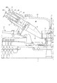
図2は、図1の燃焼器の拡大図である。燃焼器12は、外筒31の内部に所定間隔をあけて空気通路30を形成するように内筒32が支持され、内筒32の先端部に尾筒33が連結されることで、回転軸Lに対して傾斜した中心軸Sに沿って延在する燃焼器ケーシングが構成されている。
FIG. 2 is an enlarged view of the combustor of FIG. The
外筒31は、タービン車室20を構成する車室ハウジング27に対して固定されている。内筒32は、その中心部に、中心軸Sに沿ってパイロットバーナ35が設けられている。また、内筒32は、その内部であってパイロットバーナ35の周囲に、メインバーナ36が複数設けられている。メインバーナ36は、パイロットバーナ35(中心軸S)を中心とした半径方向外側に、パイロットバーナ35を取り囲むように中心軸Sを中心とする周方向に沿って等間隔で、かつパイロットバーナ35と平行に設けられている。尾筒33は、その基端が円筒状に形成されて内筒32に連結されている。尾筒33は、先端側にかけて断面積が小さくかつ湾曲して形成され、タービン13の1段目の静翼21に向けて開口している。
The
図3は、図2の燃焼器の内部構成を概略的に示す図であり、図4は、図3の燃焼器のメインバーナを下流側から視た拡大図であり、図5は、図3の燃焼器のメインバーナの拡大図である。 3 is a diagram schematically showing the internal configuration of the combustor of FIG. 2, FIG. 4 is an enlarged view of the main burner of the combustor of FIG. 3 viewed from the downstream side, and FIG. It is an enlarged view of the main burner of the combustor.
パイロットバーナ35は、その先端部のパイロットノズル35aが、筒状で先端側が広角して形成された燃焼筒35A内に配置されている。また、パイロットバーナ35は、その外周面と燃焼筒35Aの内周面との間にパイロットスワラ35Bが設けられている。
The
メインバーナ36は、その先端部のメインノズル36aが、円筒状のメインバーナ筒36A内に配置されている。メインバーナ筒36Aは、メインノズル36aにより燃料が噴射される下流側(図3および図5の右側)に、延長管36Bが設けられている。延長管36Bは、メインバーナ筒36Aから下流側に延在して設けられている。
The
延長管36Bは、図4および図5に示すように、メインバーナ筒36Aに繋がる入口36Baがメインバーナ筒36Aと同様の円形状に形成されている。また、延長管36Bは、下流側の出口36Bbが、中心軸Sを中心とした半径方向に対して平行な2つの半径方向エッジ36Bcと、各半径方向エッジ36Bcの両端を連結するように中心軸Sを中心とした周方向に沿う2つの周方向エッジ36Bdとで台形状に形成されている。周方向エッジ36Bdは、中心軸Sに対して半径方向で近い内側の周方向エッジ36Bdと、中心軸Sに対して半径方向で遠い外側の周方向エッジ36Bdとがある。また、半径方向エッジ36Bcと周方向エッジ36Bdとが連結する角部36Beは、円弧状に形成されている。この延長管36Bは、入口36Ba側の円形状から出口36Bb側の台形状に滑らかに変化して形成されている。
As shown in FIGS. 4 and 5, the
また、メインバーナ36は、メインノズル36aの外周面とメインバーナ筒36Aの内周面との間にメインスワラ36Cが設けられている。
The
外筒31は、その基端部にトップハット部34が設けられている。トップハット部34は、外筒31の基端部の内周面に沿って配置されて、外筒31の外側に空気通路30の一部を形成する筒状部材34Aと、当該筒状部材34Aの基端側の開口を閉塞する蓋部材34Bとで構成されている。蓋部材34Bは、上述のパイロットバーナ35の基端が支持され、当該パイロットバーナ35の燃料ポート35Cが外側に配置されている。この燃料ポート35Cは、図示しないパイロットバーナ燃料ラインが接続されてパイロットバーナ35に燃料が供給される。また、蓋部材34Bは、上述のメインバーナ36の基端が支持され、当該メインバーナ36の燃料ポート36Dが外側に配置されている。この燃料ポート36Dは、図示しないメインバーナ燃料ラインが接続されてメインバーナ36に燃料が供給される。
The
外筒31は、トップハット部34の筒状部材34A内において、基端側に隔壁37が設けられている。この隔壁37により空気通路30が内筒32に連通される。外筒31(トップハット部34の筒状部材34A)と内筒32との間であって、空気通路30の入口部分には、整流板38が設けられている。整流板38は、空気通路30を塞ぐように設けられ、空気通路30の上流側と下流側とを連通する孔が多数形成された多孔板である。
The
このようなガスタービン燃焼器12では、高温・高圧の圧縮空気が空気通路30に流れ込むと、圧縮空気は、整流板38を通過して整流されつつ、内筒32の基端部で隔壁37により反転されて、パイロットバーナ35の燃焼筒35Aおよびメインバーナ36のメインバーナ筒36Aに誘導される。そして、圧縮空気は、メインバーナ36において、メインバーナ筒36A内でメインスワラ36Cによって旋回する気流となり、メインノズル36aから噴射された燃料と延長管36B内で混合され予混合気となって尾筒33内に流れ込む。また、圧縮空気は、パイロットバーナ35において、燃焼筒35A内でパイロットスワラ35Bによって旋回する気流となり、パイロットノズル35aから噴射された燃料と混合され、図示しない種火により着火されて燃焼し、燃焼ガスとなって尾筒33内に噴出する。このとき、燃焼ガスの一部が尾筒33内に火炎を伴って周囲に拡散するように噴出することで、各メインバーナ36から尾筒33内に流れ込んだ予混合気に着火されて燃焼する。
In such a
すなわち、パイロットバーナ35から噴射したパイロット燃料による拡散火炎により、メインバーナ36からの希薄予混合燃料の安定燃焼を行うための保炎を行うことができる。また、メインバーナ36によって燃料を予混合することで、燃料濃度を均一化し低NOx化を図ることができる。このとき、メインバーナ36のメインバーナ筒36Aおよび延長管36Bの内部が予混合領域となり、パイロットバーナ35からの拡散火炎によって予混合気が燃焼する領域が燃焼領域となる。燃焼領域は、燃焼筒35Aの下流であり、尾筒33の内部にある。従って、予混合気が燃焼した燃焼ガスは、尾筒33の内部を流れる。
That is, the flame holding for stable combustion of the lean premixed fuel from the
ところで、このような予混合方式の燃焼器12では、メインスワラ36Cの下流において、メインバーナ筒36A内を流れる予混合気が旋回流となる。このため、燃焼領域から予混合領域への逆火(フラッシュバック)が生じやすい。具体的に、メインノズル36aから噴射された燃料は、旋回流によってメインバーナ筒36Aの内部全体にわたって均一化される。このため、燃料の濃度分布は、メインバーナ筒36Aの中央部から内壁面部にかけてほぼ一定である。これに対し、予混合気の速度は、内壁面において0となり、内壁面から離れるに従い速度が上昇し(速度境界層)、速度境界層の外側(メインバーナ筒36Aの中央部側)で速度はほぼ一定となる。すなわち、メインバーナ筒36Aおよび延長管36Bの内壁面の近傍には、速度が低い速度境界層が存在するのに対し、速度境界層において燃料濃度が高いため、この速度境界層に燃焼領域からのフラッシュバックが生じやすくなる。
By the way, in such a
特に、本実施形態では、延長管36Bが、入口36Baを円形状に形成され、出口36Bbを台形状に形成されている。これにより、延長管36Bの出口36Bbにおいて流速の低い部分が生じることが発明者等の研究により判明した。具体的には、半径方向内側の周方向エッジ36Bdの部分と、半径方向外側の両角部36Beとが顕著である。このため、流速の低い部分において、フラッシュバックが生じやすく、延長管36Bの内壁面が高温となり、燃焼器12が損傷するおそれがある。これを避けるため、本実施形態では、以下のようにメインバーナ36を構成する。
In particular, in the present embodiment, the
図5に示すように、メインバーナ筒36Aの外側に空気通路36Eを有する。空気通路36Eは、内筒32の内側にメインバーナ筒36Aの外側を覆う外周筒39が設けられ、内筒32の内周面の一部および外周筒39の内周面と、メインバーナ筒36Aの外周面との間に形成されている。この空気通路36Eは、空気通路30に通じている。また、延長管36Bの入口36Ba側に、空気通路36Eと延長管36B内とを連通する連通穴H1を有する。延長管36Bの入口36Ba側とは、メインノズル36aよりも下流側の位置であって、円形状に形成された位置である。また、連通穴H1は、延長管36B内の開口が、延長管36Bの出口36Bb側(下流側)に向くように斜めに形成されている。連通穴H1は、延長管36Bの出口36Bbにおける流速の低い部分に対応し、以下のように配置されている。
As shown in FIG. 5, an
図6は、貫通穴の配置を示す図であり、図7は、貫通穴の配置の他の例を示す図である。図6および図7では、図4と同様にメインバーナ36を下流側から視ている。連通穴H1は、延長管36Bの出口36Bbにおいて、半径方向内側の周方向エッジ36Bdの部分と、半径方向外側の両角部36Beとに対応して設けられている。
FIG. 6 is a diagram illustrating the arrangement of the through holes, and FIG. 7 is a diagram illustrating another example of the arrangement of the through holes. 6 and 7, the
図6において、連通穴H1は、半径方向内側の周方向エッジ36Bdの部分に対応して設けられた内側連通穴H1aと、両角部36Beの部分にそれぞれ対応して設けられた角部連通穴H1bとが、各部分に分けて設けられ、かつ所定範囲でスリット状に連続して形成されている。 In FIG. 6, the communication hole H1 includes an inner communication hole H1a provided corresponding to the radially inner circumferential edge 36Bd and a corner communication hole H1b provided corresponding to both corners 36Be. Are provided separately in each part and continuously formed in a slit shape within a predetermined range.
所定範囲について説明する。図6に示すように、メインバーナ36を下流側から視て旋回流が反時計回りの場合において、半径方向外側の周方向エッジ36Bdの中央を0degとする。半径方向内側の周方向エッジ36Bdに対応する内側連通穴H1aは、図6中の二点差線の間A−Bの範囲に設けられる。また、角部36Be(旋回流の上流側(図6の右側))に対応する角部連通穴H1bは、図6中の二点差線の間E−Fの範囲に設けられる。さらに、角部36Be(旋回流の下流側(図6の左側)に対応する角部連通穴H1bは、図6中の二点差線の間C−Dの範囲に設けられる。このように、各連通穴H1a,H1bは、周方向に不均等な配置であり、これは旋回流の影響を加味したものである。具体的には、上述したように、メインスワラ36Cの下流において、メインバーナ筒36A内を流れる予混合気が旋回流となる。図6ではメインバーナ36を下流側から視て旋回流が反時計回りであり、各連通穴H1a,H1bからメインバーナ筒36Aに導入された空気通路30の圧縮空気の一部は、旋回流に流されるように反時計回りに流動しつつ下流側に流れる。このため、旋回流の流れ方向や、各連通穴H1a,H1bから延長管36Bの出口36Bbまでの距離などによる影響を加味し、各連通穴H1a,H1bの範囲を旋回流とは逆方向となる時計回りにずらした範囲とすることで、延長管36Bの出口36Bbにおいて、半径方向内側の周方向エッジ36Bdの中央位置(180deg)を基準としたほぼ対称の範囲や、角部36Beの最も窄まった位置を基準としたほぼ対称の範囲に、各連通穴H1a,H1bからメインバーナ筒36Aに導入された空気が至ることになる。
The predetermined range will be described. As shown in FIG. 6, when the swirl flow is counterclockwise when the
図6に示すように、連通穴H1を設けることにより、空気通路30の圧縮空気の一部が空気通路36Eから連通穴H1を介してメインバーナ筒36Aに導入され、図5に示すように、フィルム状の空気(フィルム空気)となってメインバーナ筒36Aおよび延長管36Bの内壁面に沿って下流側に流れる。このフィルム空気は、壁面近傍の低流速領域の燃料濃度を低減する。このため、フラッシュバックの発生を抑制することができる。
As shown in FIG. 6, by providing the communication hole H1, a part of the compressed air in the
特に、本実施形態の燃焼器12は、延長管36Bの出口36Bbにおける流速の低い部分に対応し、内側連通穴H1aと角部連通穴H1bとを設けたことで、フラッシュバックの発生を抑制しつつ、フィルム空気の偏りをより抑制することができる。
In particular, the
なお、上述した実施形態の燃焼器12において、内側連通穴H1aおよび角部連通穴H1bの双方を設けることで、フラッシュバックの発生を抑制しつつ、フィルム空気の偏りを抑制する効果を顕著に得ることが可能である。内側連通穴H1aまたは角部連通穴H1bの一方であっても、フラッシュバックの発生を抑制しつつ、フィルム空気の偏りを抑制する効果を得ることができる。内側連通穴H1aまたは角部連通穴H1bの一方の場合、パイロットバーナ35からの火炎に近くフラッシュバックの影響が大きい部分である半径方向内側の周方向エッジ36Bdに対応する内側連通穴H1aを設けることが好ましい。また、内側連通穴H1aまたは角部連通穴H1bの一方の場合、半径方向に広がって流体を拡散させ流速が特に低くなりやすい部分である角部36Beに対応する角部連通穴H1bを設けることが好ましい。
In the
また、半径方向内側の周方向エッジ36Bdは、パイロットバーナ35からの火炎に近くフラッシュバックの影響が大きい部分であるため、内側連通穴H1aおよび角部連通穴H1bの双方を設ける場合は、フラッシュバックの発生を抑制する効果を顕著に得るため、内側連通穴H1aが角部連通穴H1bよりも開口面積が大きく形成されていることが好ましい。
Further, since the circumferential edge 36Bd on the radially inner side is a portion close to the flame from the
図7において、連通穴H1は、半径方向内側の周方向エッジ36Bdの部分に対応して設けられた内側連通穴H1aと、両角部36Beの部分にそれぞれ対応して設けられた角部連通穴H1bとが、周方向に沿って設けられている。この場合、内側連通穴H1aは所定範囲でスリット状に連続して形成され、角部連通穴H1bは、内側連通穴H1aを除く範囲で断続して形成されている。 In FIG. 7, the communication hole H1 includes an inner communication hole H1a provided corresponding to the radially inner circumferential edge 36Bd and a corner communication hole H1b provided corresponding to both corners 36Be. Are provided along the circumferential direction. In this case, the inner communication hole H1a is continuously formed in a slit shape within a predetermined range, and the corner communication hole H1b is formed intermittently in a range excluding the inner communication hole H1a.
所定範囲について説明する。図7に示すように、メインバーナ36を下流側から視て旋回流が反時計回りの場合において、半径方向外側の周方向エッジ36Bdの中央を0degとする。半径方向内側の周方向エッジ36Bdに対応する内側連通穴H1aは、図7中の二点差線の間A−Bの範囲に設けられる。また、角部36Beに対応する角部連通穴H1bは、残りの範囲で、断続した小孔として設けられる。連通穴H1aは、周方向に不均等な配置であり、これは上述したように旋回流の影響を加味したものである。
The predetermined range will be described. As shown in FIG. 7, when the swirl flow is counterclockwise when the
図7に示すように、連通穴H1を設けることにより、空気通路30の圧縮空気の一部が空気通路36Eから連通穴H1を介してメインバーナ筒36Aに導入され、図5に示すように、フィルム状の空気(フィルム空気)となってメインバーナ筒36Aおよび延長管36Bの内壁面に沿って流れる。このフィルム空気は、壁面近傍の低流速領域の燃料濃度を低減する。このため、フラッシュバックの発生を抑制することができる。
As shown in FIG. 7, by providing the communication hole H1, a part of the compressed air in the
特に、本実施形態の燃焼器12は、延長管36Bの出口36Bbにおける流速の低い部分に対応し、内側連通穴H1aと角部連通穴H1bとを設けたことで、フィルム空気の偏りを抑制することができ、フラッシュバックの発生を抑制する効果を顕著に得ることができる。しかも、角部連通穴H1bが、内側連通穴H1aを除く範囲で断続して形成されているため、パイロットバーナ35からの火炎に近くフラッシュバックの影響が大きい部分である半径方向内側の周方向エッジ36Bdに対応する内側連通穴H1a側に比較的多くの空気を供給することができる。
In particular, the
ところで、メインスワラの上流側は、流速が低くなりやすく燃料濃度が濃い傾向となる。従って、メインスワラの下流端に対応する位置に翼部連通穴H2を設けることで、この翼部連通穴H2からメインバーナ筒36Aに導入された圧縮空気により、フラッシュバックの火炎を堰き止めることができる。
By the way, on the upstream side of the main swirler, the flow rate tends to be low and the fuel concentration tends to be high. Therefore, by providing the blade communication hole H2 at a position corresponding to the downstream end of the main swirler, the flashback flame can be blocked by the compressed air introduced from the blade communication hole H2 into the
また、上述した燃焼器12を備えるガスタービン10によれば、フラッシュバックの抑制により燃焼器12の損傷を防ぐことで、タービン性能を維持することができる。
Moreover, according to the
10 ガスタービン
11 圧縮機
12 燃焼器
13 タービン
35 パイロットバーナ
36 メインバーナ
36a メインノズル
36A メインバーナ筒
36B 延長管
36Ba 入口
36Bb 出口
36Bc 半径方向エッジ
36Bd 周方向エッジ
36Be 角部
36C メインスワラ
36E 空気通路
H1a 内側連通穴
H1b 角部連通穴
H2 翼部連通穴
DESCRIPTION OF
Claims (12)
前記パイロットバーナを中心とした半径方向外側に周方向に沿って複数設けられて、メインバーナ筒内にメインノズルが配置されたメインバーナと、
各前記メインバーナの前記メインバーナ筒から下流側に延在して設けられており、前記メインバーナ筒に繋がる入口が円形状で、下流側の出口が半径方向に平行な2つの半径方向エッジ、および各前記半径方向エッジの両端を連結するように周方向に沿う2つの周方向エッジで形成された延長管と、
前記メインバーナ筒の外側に設けられた空気通路と、
前記延長管の入口側であって前記半径方向の内側の周方向エッジに対応する位置に設けられ前記空気通路と前記延長管内とを連通する内側連通穴と、
を備え、
前記内側連通穴は前記延長管に形成されることを特徴とする燃焼器。 With a pilot burner,
A plurality of main burners which are provided along the circumferential direction on the radially outer side centering on the pilot burner, and in which a main nozzle is disposed in the main burner cylinder;
Each of the main burners is provided to extend downstream from the main burner cylinder, the inlet connected to the main burner cylinder is circular, and the downstream outlet is two radial edges parallel to the radial direction, And an extension tube formed by two circumferential edges along the circumferential direction to connect both ends of each said radial edge;
An air passage provided outside the main burner tube;
An inner communication hole provided at a position corresponding to a circumferential edge on the inner side in the radial direction on the inlet side of the extension pipe, and communicating the air passage with the inside of the extension pipe;
With
The combustor, wherein the inner communication hole is formed in the extension pipe.
前記パイロットバーナを中心とした半径方向外側に周方向に沿って複数設けられて、メインバーナ筒内にメインノズルが配置されたメインバーナと、
各前記メインバーナの前記メインバーナ筒から下流側に延在して設けられており、前記メインバーナ筒に繋がる入口が円形状で、下流側の出口が半径方向に平行な2つの半径方向エッジ、および各前記半径方向エッジの両端を連結するように周方向に沿う2つの周方向エッジで形成された延長管と、
前記メインバーナ筒の外側に設けられた空気通路と、
前記延長管の入口側であって前記半径方向の外側の周方向エッジと前記半径方向エッジとが連通する角部に対応する位置に設けられ前記空気通路と前記延長管内とを連通する角部連通穴と、
を備え、
前記角部連通穴は前記延長管に設けられることを特徴とする燃焼器。 With a pilot burner,
A plurality of main burners which are provided along the circumferential direction on the radially outer side centering on the pilot burner, and in which a main nozzle is disposed in the main burner cylinder;
Each of the main burners is provided to extend downstream from the main burner cylinder, the inlet connected to the main burner cylinder is circular, and the downstream outlet is two radial edges parallel to the radial direction, And an extension tube formed by two circumferential edges along the circumferential direction to connect both ends of each said radial edge;
An air passage provided outside the main burner tube;
Corner communication that communicates between the air passage and the inside of the extension pipe provided at a position corresponding to a corner on the inlet side of the extension pipe and where the circumferential edge on the outer side in the radial direction and the radial edge communicate with each other. With holes,
With
The combustor, wherein the corner communication hole is provided in the extension pipe.
請求項1〜11のいずれか1つに記載の燃焼器が適用されることを特徴とするガスタービン。 In a gas turbine comprising a compressor, a combustor, and a turbine,
A gas turbine to which the combustor according to any one of claims 1 to 11 is applied.
Priority Applications (6)
| Application Number | Priority Date | Filing Date | Title |
|---|---|---|---|
| JP2013018481A JP6025587B2 (en) | 2013-02-01 | 2013-02-01 | Combustor and gas turbine |
| US14/762,577 US9933162B2 (en) | 2013-02-01 | 2014-01-10 | Combustor and gas turbine |
| DE112014000652.1T DE112014000652B4 (en) | 2013-02-01 | 2014-01-10 | Combustion chamber and gas turbine |
| CN201480005858.5A CN104937344B (en) | 2013-02-01 | 2014-01-10 | Burner and gas turbine |
| KR1020157020230A KR101685865B1 (en) | 2013-02-01 | 2014-01-10 | Combustor and gas turbine |
| PCT/JP2014/050360 WO2014119358A1 (en) | 2013-02-01 | 2014-01-10 | Combustor and gas turbine |
Applications Claiming Priority (1)
| Application Number | Priority Date | Filing Date | Title |
|---|---|---|---|
| JP2013018481A JP6025587B2 (en) | 2013-02-01 | 2013-02-01 | Combustor and gas turbine |
Publications (3)
| Publication Number | Publication Date |
|---|---|
| JP2014149127A JP2014149127A (en) | 2014-08-21 |
| JP2014149127A5 JP2014149127A5 (en) | 2015-11-05 |
| JP6025587B2 true JP6025587B2 (en) | 2016-11-16 |
Family
ID=51262073
Family Applications (1)
| Application Number | Title | Priority Date | Filing Date |
|---|---|---|---|
| JP2013018481A Active JP6025587B2 (en) | 2013-02-01 | 2013-02-01 | Combustor and gas turbine |
Country Status (6)
| Country | Link |
|---|---|
| US (1) | US9933162B2 (en) |
| JP (1) | JP6025587B2 (en) |
| KR (1) | KR101685865B1 (en) |
| CN (1) | CN104937344B (en) |
| DE (1) | DE112014000652B4 (en) |
| WO (1) | WO2014119358A1 (en) |
Families Citing this family (4)
| Publication number | Priority date | Publication date | Assignee | Title |
|---|---|---|---|---|
| JP6417620B2 (en) * | 2014-10-24 | 2018-11-07 | 三菱日立パワーシステムズ株式会社 | Combustor, gas turbine |
| CN105645343B (en) * | 2016-02-29 | 2018-06-05 | 中国航空工业集团公司沈阳飞机设计研究所 | A kind of two-way pressure filling balance Control Scheme method |
| JP6634658B2 (en) | 2016-12-20 | 2020-01-22 | 三菱重工業株式会社 | Main nozzle, combustor and method of manufacturing main nozzle |
| WO2019018043A1 (en) * | 2017-07-19 | 2019-01-24 | Parker-Hannifin Corporation | Dual-fuel multi-port connector |
Family Cites Families (16)
| Publication number | Priority date | Publication date | Assignee | Title |
|---|---|---|---|---|
| US5193346A (en) | 1986-11-25 | 1993-03-16 | General Electric Company | Premixed secondary fuel nozzle with integral swirler |
| US5251447A (en) | 1992-10-01 | 1993-10-12 | General Electric Company | Air fuel mixer for gas turbine combustor |
| JP3300754B2 (en) | 1998-02-09 | 2002-07-08 | 三菱重工業株式会社 | Combustor |
| US6038861A (en) * | 1998-06-10 | 2000-03-21 | Siemens Westinghouse Power Corporation | Main stage fuel mixer with premixing transition for dry low Nox (DLN) combustors |
| JP3035289B1 (en) | 1999-03-11 | 2000-04-24 | 三菱重工業株式会社 | Hybrid combustor |
| US6427446B1 (en) * | 2000-09-19 | 2002-08-06 | Power Systems Mfg., Llc | Low NOx emission combustion liner with circumferentially angled film cooling holes |
| JP4524902B2 (en) * | 2000-10-25 | 2010-08-18 | 株式会社Ihi | Low NOx combustor with premixed fuel injection valve |
| JP3962554B2 (en) | 2001-04-19 | 2007-08-22 | 三菱重工業株式会社 | Gas turbine combustor and gas turbine |
| JP4610800B2 (en) | 2001-06-29 | 2011-01-12 | 三菱重工業株式会社 | Gas turbine combustor |
| JP4070758B2 (en) * | 2004-09-10 | 2008-04-02 | 三菱重工業株式会社 | Gas turbine combustor |
| US8113000B2 (en) | 2008-09-15 | 2012-02-14 | Siemens Energy, Inc. | Flashback resistant pre-mixer assembly |
| US8307657B2 (en) | 2009-03-10 | 2012-11-13 | General Electric Company | Combustor liner cooling system |
| JP2010236739A (en) * | 2009-03-31 | 2010-10-21 | Hitachi Ltd | Gas turbine combustor |
| KR101318553B1 (en) | 2009-08-13 | 2013-10-16 | 미츠비시 쥬고교 가부시키가이샤 | Combustor |
| JP5766444B2 (en) | 2011-01-14 | 2015-08-19 | 三菱日立パワーシステムズ株式会社 | Combustor and gas turbine |
| JP6021108B2 (en) * | 2012-02-14 | 2016-11-02 | 三菱日立パワーシステムズ株式会社 | Gas turbine combustor |
-
2013
- 2013-02-01 JP JP2013018481A patent/JP6025587B2/en active Active
-
2014
- 2014-01-10 US US14/762,577 patent/US9933162B2/en active Active
- 2014-01-10 WO PCT/JP2014/050360 patent/WO2014119358A1/en active Application Filing
- 2014-01-10 CN CN201480005858.5A patent/CN104937344B/en active Active
- 2014-01-10 DE DE112014000652.1T patent/DE112014000652B4/en active Active
- 2014-01-10 KR KR1020157020230A patent/KR101685865B1/en active IP Right Grant
Also Published As
| Publication number | Publication date |
|---|---|
| JP2014149127A (en) | 2014-08-21 |
| KR20150102092A (en) | 2015-09-04 |
| CN104937344A (en) | 2015-09-23 |
| US20150362193A1 (en) | 2015-12-17 |
| DE112014000652B4 (en) | 2019-07-18 |
| WO2014119358A1 (en) | 2014-08-07 |
| KR101685865B1 (en) | 2016-12-12 |
| DE112014000652T5 (en) | 2015-11-19 |
| US9933162B2 (en) | 2018-04-03 |
| CN104937344B (en) | 2017-09-22 |
Similar Documents
| Publication | Publication Date | Title |
|---|---|---|
| JP6203530B2 (en) | Fuel / air premixing system for turbine engines | |
| JP5524407B2 (en) | Gas turbine combustor and gas turbine | |
| JP6177187B2 (en) | Gas turbine combustor, gas turbine, control apparatus and control method | |
| US8950190B2 (en) | Gas turbine combustor having contraction member on inner wall surface | |
| JP6723768B2 (en) | Burner assembly, combustor, and gas turbine | |
| US9989258B2 (en) | Premixed-combustion gas turbine combustor | |
| US10570820B2 (en) | Nozzle, combustion apparatus, and gas turbine | |
| EP3102877B1 (en) | Combustor | |
| JP2014092286A5 (en) | ||
| JP6025587B2 (en) | Combustor and gas turbine | |
| US10961910B2 (en) | Combustion cylinder, gas turbine combustor, and gas turbine | |
| JP2011196680A (en) | Multiple zone pilot for low emission combustion system | |
| JP2019532247A (en) | Pilot burner assembly with central pilot fuel injection for a gas turbine engine combustor | |
| JP2012145312A (en) | Combustor and gas turbine | |
| JP5606346B2 (en) | Gas turbine combustor | |
| KR20170045277A (en) | Combustor and gas turbine | |
| JP2013145077A (en) | Gas turbine combustor | |
| US20180363904A1 (en) | Combustor for a gas turbine | |
| JP2008298351A (en) | Combustion device for gas turbine engine |
Legal Events
| Date | Code | Title | Description |
|---|---|---|---|
| A711 | Notification of change in applicant |
Free format text: JAPANESE INTERMEDIATE CODE: A712 Effective date: 20150206 |
|
| A625 | Written request for application examination (by other person) |
Free format text: JAPANESE INTERMEDIATE CODE: A625 Effective date: 20150903 |
|
| A521 | Written amendment |
Free format text: JAPANESE INTERMEDIATE CODE: A523 Effective date: 20150915 |
|
| A131 | Notification of reasons for refusal |
Free format text: JAPANESE INTERMEDIATE CODE: A131 Effective date: 20160809 |
|
| A521 | Written amendment |
Free format text: JAPANESE INTERMEDIATE CODE: A523 Effective date: 20160819 |
|
| TRDD | Decision of grant or rejection written | ||
| A01 | Written decision to grant a patent or to grant a registration (utility model) |
Free format text: JAPANESE INTERMEDIATE CODE: A01 Effective date: 20160913 |
|
| A61 | First payment of annual fees (during grant procedure) |
Free format text: JAPANESE INTERMEDIATE CODE: A61 Effective date: 20161011 |
|
| R151 | Written notification of patent or utility model registration |
Ref document number: 6025587 Country of ref document: JP Free format text: JAPANESE INTERMEDIATE CODE: R151 |
|
| S533 | Written request for registration of change of name |
Free format text: JAPANESE INTERMEDIATE CODE: R313533 |
|
| R350 | Written notification of registration of transfer |
Free format text: JAPANESE INTERMEDIATE CODE: R350 |