JP6022420B2 - Rail car axle box support device - Google Patents
Rail car axle box support device Download PDFInfo
- Publication number
- JP6022420B2 JP6022420B2 JP2013150660A JP2013150660A JP6022420B2 JP 6022420 B2 JP6022420 B2 JP 6022420B2 JP 2013150660 A JP2013150660 A JP 2013150660A JP 2013150660 A JP2013150660 A JP 2013150660A JP 6022420 B2 JP6022420 B2 JP 6022420B2
- Authority
- JP
- Japan
- Prior art keywords
- axle box
- shaft
- support device
- rubber
- box support
- Prior art date
- Legal status (The legal status is an assumption and is not a legal conclusion. Google has not performed a legal analysis and makes no representation as to the accuracy of the status listed.)
- Active
Links
Images


Description
本発明は、鉄道車両用軸箱支持装置に関するものである。 The present invention relates to a rail car axle box support device.
鉄道車両が直線区間等を高速走行する際に輪軸、台車等が激しく左右方向及びヨー方向に振動する、蛇行動と呼ばれる自励振動が発生し、不安定な状態になる場合がある。そこで、高速走行時に安定な状態を保つために、輪軸、台車を高剛性で支持することにより、走行安定性を維持する必要がある。
一方、鉄道車両が曲線を走行する場合は、車輪とレールの間に左右方向に生じる力である横圧が発生する。著大な横圧は、車輪及びレールの摩耗を促進し、車輪レール間のきしみ等による振動・騒音の発生を招き、軌道破壊、脱線の発生を確実に予防するため、保守費が高騰するという問題がある。
When a railway vehicle travels at a high speed in a straight section or the like, a self-excited vibration called a snake action that vibrates in the left and right directions and the yaw direction vigorously occurs in the wheel shaft and the carriage, and may become unstable. Therefore, in order to maintain a stable state during high speed traveling, it is necessary to maintain traveling stability by supporting the wheel shaft and the carriage with high rigidity.
On the other hand, when the railway vehicle travels along a curve, a lateral pressure, which is a force generated in the left-right direction, is generated between the wheel and the rail. The significant lateral pressure accelerates the wear of the wheels and rails, causes vibration and noise due to squeaks between the wheel rails, and reliably prevents the occurrence of track destruction and derailment. There's a problem.
このため、車輪やレールの保守費を低減し、快適な乗り心地を実現するとともに、安全性を確保する観点から、横圧を低減し、曲線通過性能を向上させることが望ましい。すなわち、曲線通過時に輪軸及び台車を曲線の接線方向に向けて、曲線の変化に沿うスムーズな走行を実現するため、輪軸、台車を柔らかめに支持することにより操舵性能を向上させ、横圧と軌道に対する負荷を低減した状態で走行する必要がある。 For this reason, it is desirable to reduce the maintenance cost of wheels and rails, to realize a comfortable riding comfort, and to reduce the lateral pressure and improve the curve passing performance from the viewpoint of ensuring safety. In other words, to achieve smooth running along the curve by turning the wheel shaft and the trolley in the tangential direction of the curve when passing the curve, the steering performance is improved by supporting the wheel shaft and the trolley softly, and the lateral pressure and It is necessary to travel with a reduced load on the track.
このように、鉄道車両では、高速走行時と曲線走行時とで、輪軸及び台車の支持剛性の最適値が異なるため、高速走行安定性と曲線通過性能はトレードオフの関係となり、両走行性能をバランスさせるため、台車支持構造の最適設計が必要となる。
特許文献1には、車体の前部と後部とを、それぞれ2軸のボルスタレス方式の操舵台車で支持した鉄道車両において、前部の台車の前側の輪軸と後部の台車の後側の輪軸に対する前後方向支持剛性を相対的に柔とし、前部の台車の後側の輪軸及び後部の台車の前側の輪軸に対する前後方向支持剛性を相対的に剛とし、車両全体に見たとき、「柔、剛、剛、柔」となるようにすることが記載されている。
In this way, in railway vehicles, the optimum values of the wheel and carriage support stiffness differ between high-speed traveling and curved traveling, so there is a trade-off between high-speed traveling stability and curve passing performance, and both traveling performances are In order to achieve a balance, an optimum design of the cart support structure is required.
In Patent Document 1, in a railway vehicle in which a front part and a rear part of a vehicle body are each supported by a two-axis bolsterless type steering carriage, front and rear of the front axle of the front carriage and the rear axle of the rear carriage The directional support rigidity is relatively soft, and the longitudinal support rigidity with respect to the rear wheel axle of the front carriage and the front wheel axle of the rear carriage is relatively rigid. It is described that it becomes “, rugged, soft”.
また、特許文献2には、軸箱上部と台車枠のバネ帽との間に配置されるコイルバネ内に、軸箱を支持する軸箱上部円筒積層ゴムを配設するとともに、車体前後方向に延びる軸箱の支持腕を軸箱側部円筒積層ゴムを介して台車枠に支持させ、両円筒積層の少なくとも一方の剛性を切り替え可能とすることが記載されている。
In
特許文献1に記載された輪軸支持では、同一車両の4つの輪軸を、前から柔・剛・剛・柔の順番で支持することにより、走行安定性を維持しつつ、曲線通過性能を向上させている。
しかし、最高速度をさらに高めようとする場合に、支持剛性を柔とした輪軸の影響で走行安定性が低下するという問題がある。また、台車枠と軸箱間の上下方向をゴムで支持しており、ゴムは振動数が高くなるほど動剛性が高くなる特性を有するため、高速走行時に上下方向の動剛性が高くなり、上下方向の振動伝達率が大きくなり、乗り心地が悪化するという問題がある。
In the wheel shaft support described in Patent Document 1, the four wheel shafts of the same vehicle are supported in the order of soft, rigid, rigid, and soft from the front, thereby improving the curve passing performance while maintaining running stability. ing.
However, when the maximum speed is to be further increased, there is a problem that the running stability is lowered due to the influence of the wheel shaft with soft support rigidity. In addition, the vertical direction between the carriage frame and the axle box is supported by rubber, and rubber has the characteristic that the higher the frequency, the higher the dynamic rigidity. There is a problem that the vibration transmissibility of the vehicle increases and the ride comfort deteriorates.
一方、特許文献2の軸箱支持装置では、2つの円筒積層ゴムを配置することにより、軽量化・台車長の短縮を図り、さらに円筒積層ゴムの剛性を調整することにより、軸箱支持剛性を確保している。また、円筒積層ゴムに粘性流体を封入し、電磁弁により流路を切り替え、高速走行時には、動的な剛性が高くなるように、そして、在来線の曲線通過時には、動的な剛性が低くなるように切り替えている。
しかし、円筒積層ゴムのゴム部内に粘性流体を封入する構造のため、油漏れした場合、粘性流体を封入した円筒積層ゴムの剛性が低下し、軸箱支持装置の十分な前後支持剛性を確保できず、高速走行時の安定性が悪化するという問題がある。
On the other hand, in the axle box support device of
However, due to the structure in which the viscous fluid is sealed in the rubber part of the cylindrical laminated rubber, if oil leaks, the rigidity of the cylindrical laminated rubber filled with the viscous fluid will be reduced, and sufficient longitudinal support rigidity of the axle box support device can be secured. However, there is a problem that the stability during high-speed driving deteriorates.
そこで、本発明の目的は、これらの課題を解決し、高速走行安定性と曲線通過性能確保を両立するとともに、いずれの運転状態でも快適な乗り心地を維持するため、軸箱の前後方向支持剛性をそれぞれの最適値に切り替えることで、信頼性の高い鉄道車両用の軸箱支持装置を提供することにある。 Therefore, the object of the present invention is to solve these problems, achieve both high-speed running stability and curve passing performance, and maintain a comfortable riding comfort in any driving state. Is to provide a highly reliable axle box support device for a railway vehicle.
上記課題を解決するために、例えば、特許請求の範囲に記載の構成を採用する。
本発明の鉄道車両用軸箱支持装置は上記課題を解決する手段を複数含んでいるが、その一例を挙げるならば、軸箱と台車枠間を支持する鉄道車両用軸箱支持装置において、固定軸箱支持装置および切替軸箱支持装置を、前記軸箱と前記台車枠との間に併設して設け、前記固定軸箱支持装置は、金属製スプリングからなる軸ばねを介して上下方向に弾性支持するとともに、前記軸箱に装着された軸ゴム収納部と、前記台車枠に固定し該台車枠から下方に延びる内筒との間に、上下方向に軸ゴムを配設して水平方向に弾性支持し、前記切替軸箱支持装置は、金属製スプリングからなる軸ばねを介して上下方向に弾性支持するとともに、前記軸箱に装着された軸ゴム収納部と、前記台車枠に対して下方に延びる内筒との間に、上下方向に軸ゴムを配設して水平方向に弾性支持すると共に、前記内筒の水平方向の移動を前記台車枠の側から規制する規制部材を有し、高速走行時に前記規制部材により前記内筒の水平方向の移動を規制して水平支持剛性を剛支持状態とし、曲線走行時に前記規制部材を解除して水平支持剛性を柔支持状態とする。
In order to solve the above problems, for example, the configuration described in the claims is adopted.
The rail car axle box support device of the present invention includes a plurality of means for solving the above-mentioned problems. For example, in the rail car axle box support device for supporting the space between the axle box and the carriage frame, the fixed An axle box support device and a switching axle box support device are provided between the axle box and the carriage frame, and the fixed axle box support device is elastic in the vertical direction via an axis spring made of a metal spring. A shaft rubber is disposed in the vertical direction between the shaft rubber storage portion attached to the shaft box and the inner cylinder fixed to the cart frame and extending downward from the cart frame. The switching shaft box support device is elastically supported, and is elastically supported in a vertical direction via a shaft spring made of a metal spring, and is downward with respect to a shaft rubber storage portion mounted on the shaft box and the carriage frame . between the inner tube extending, distribution shaft rubber vertically With elastically supported in a horizontal direction and has a regulating member for regulating the horizontal movement of the inner tube from the side of the truck frame, restrict the horizontal movement of the inner cylinder by the restricting member during high speed running and the horizontal supporting rigidity and rigid support state, by releasing the restriction member during cornering to the horizontal supporting rigidity and soft support state.
軸箱と台車枠間の水平方向の支持剛性は、軸ゴム収納部とロッド部との間に配設した軸ゴムにより水平方向の支持剛性が主として分担するが、本発明によれば、高速走行、曲線走行などの走行状態に応じて、ロッド部材の移動を規制あるいは解除することにより、水平方向の軸箱支持剛性を切り替え、適正な値に設定することができるため、高速走行時には剛支持状態とすることで走行安定性を向上させるとともに、曲線走行時には柔支持状態に切り替えることで、横圧を効果的に低減し、曲線通過性能を向上することができる。
また、本発明の鉄道車両用軸箱支持装置は、上下方向の支持をゴムではなく、高速走行時に動剛性が増加しない、金属製スプリングからなるコイルばね等が分担しているため、高速走行時の振動伝達率の増大を抑制し、上下振動の少ない快適な乗り心地が維持することができる。
さらに、本発明の鉄道車両用軸箱支持装置では、ロッドと内筒のテーパー状の孔からなる機構で軸箱と台車枠間の前後方向を拘束して力を伝達して、軸箱を前後方向に支持するという簡素な構造であるため、長期にわたり信頼性の高い状態で軸箱支持剛性を確保することができる。
上記した以外の課題、構成及び効果は、以下の実施形態の説明により明らかにされる。
The horizontal support rigidity between the axle box and the bogie frame is mainly shared by the horizontal support rigidity by the shaft rubber disposed between the shaft rubber storage part and the rod part. By restricting or releasing the movement of the rod member according to the traveling state such as curved traveling, the horizontal axle box support rigidity can be switched and set to an appropriate value. Thus, the running stability can be improved, and the lateral pressure can be effectively reduced and the curve passing performance can be improved by switching to the soft support state during curve running.
In addition, the rail car axle box support device according to the present invention is not made of rubber for supporting in the vertical direction, and the dynamic rigidity is not increased during high speed running, and a coil spring made of a metal spring is shared. An increase in the vibration transmissibility of the vehicle can be suppressed, and a comfortable ride with little vertical vibration can be maintained.
Furthermore, in the rail car axle box support device of the present invention, a mechanism consisting of a rod and a tapered hole in the inner cylinder restrains the front / rear direction between the axle box and the carriage frame and transmits the force to move the axle box back and forth. Because of the simple structure of supporting in the direction, the axle box support rigidity can be ensured in a highly reliable state over a long period of time.
Problems, configurations, and effects other than those described above will be clarified by the following description of embodiments.
以下、本発明の実施例を、図面を参照しつつ説明する。 Embodiments of the present invention will be described below with reference to the drawings.
[実施例1]
本発明の実施例1を、図1〜図3を用いて説明する。
図1は、本実施例の鉄道車両用台車のシステム構成図、図2は、曲線走行時に前後剛性を低減して柔支持状態となるよう切り替えた際の詳細構造、図3は、高速走行時に前後剛性を高剛性に復帰させ、剛支持状態とした際の詳細構造をそれぞれ示している。
図1に示すように、鉄道車両用台車システムは、台車枠3、軸箱4、輪軸5、軸箱支持装置1、空気ばね6により構成される。
輪軸5は、軸箱4内の軸受けを介して回転自在に支持されており、軸箱4と台車枠3の間は、本実施例による軸箱支持装置1により結合されている。なお、台車枠3と車体7との間は空気ばね6により弾性支持され、軸箱支持装置1は、車体7に搭載される制御装置8に接続されている。
[Example 1]
A first embodiment of the present invention will be described with reference to FIGS.
FIG. 1 is a system configuration diagram of a railway vehicle carriage according to the present embodiment, FIG. 2 is a detailed structure when switching to be in a soft support state by reducing the front-rear rigidity during curved traveling, and FIG. 3 is during high-speed traveling The detailed structures when the front-rear rigidity is returned to a high rigidity to be in a rigid support state are shown.
As shown in FIG. 1, the bogie system for railway vehicles includes a
The
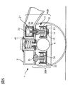
図2に、高速走行時において、剛支持状態に切り替えられた軸箱支持装置1の詳細構造を示す。
本実施例の軸箱支持装置1は、切替軸箱支持装置10と固定軸箱支持装置30から構成され、両支持装置10、30は、台車枠3の側梁9と、軸箱4の軸受け部下方から側梁9と平行に、鉄道車両7の前後方向に延びる延出部との間に結合される。
固定軸箱支持装置30は、軸ばね32、軸ゴム33、内筒34、下端側軸ばね座35により構成され、軸ばね32は、コイルばね等の金属製スプリングにより構成され、軸箱4と側梁9を連結し、主として上下方向の弾性支持を担うものである。
軸ゴム33は、円筒積層ゴム等により構成され、内筒34に外嵌され、下端側軸ばね座35に一体に形成された軸ゴム収納部に収納されている。鉄道車両7の前後方向及び左右(幅)方向に所定の弾性係数が得られるよう、軸ゴム33の材質や厚さが選定され、軸箱4と側梁9との間を、軸ばね座35と内筒34を介して連結し、水平面内において前後方向と左右方向の弾性支持を主として担うものである。
以下、鉄道車両の進行方向からみて、前後方向(図2において左右方向)及び左右(幅)方向(図2において紙面に直交する方向)を合わせて、以下、「水平方向」、軸ゴムによる「水平方向の支持剛性」を「水平支持剛性」と称する。
FIG. 2 shows a detailed structure of the axle box support device 1 that is switched to the rigid support state during high-speed traveling.
The axle box support device 1 of the present embodiment is composed of a switching axle
The fixed shaft
The
Hereinafter, the front and rear direction (left and right direction in FIG. 2) and the left and right (width) direction (direction perpendicular to the paper surface in FIG. 2) in combination with the traveling direction of the railway vehicle are referred to as “horizontal direction” and “ The “horizontal support rigidity” is referred to as “horizontal support rigidity”.
切替軸箱支持装置10は、軸ばね部11、切替装置21から構成され、軸ばね部11は、軸ばね12、軸ゴム13、内筒14、下端側軸ばね座15、上端側軸ばね座16、そして、規制部材としてのロッド23とから構成される。軸ばね12は、固定軸箱支持装置30の軸ばね32と同様、コイルばね等の金属性スプリングにより構成され、軸箱4と側梁9との間を、下端側軸ばね座15と上端側軸ばね座16を介して連結し、主として上下方向に弾性支持する。
軸ゴム13は、固定軸箱支持装置30の軸ゴム33と同様、円筒積層ゴム等から構成され、内筒14に外嵌され、下端側軸ばね座15に一体に形成された軸ゴム収納部に収納されている。やはり、水平方向に所定の弾性係数が得られるように、材質や厚さが選定されており、軸箱4と側梁9との間を、上端側軸ばね座16、及び、下端側軸ばね座15を介して連結し、水平方向の弾性支持を主として担うものである。なお、内筒14の上端側にはテーパー状の孔17が設けられている。
The switching shaft
The
切替装置21は、アクチュエータ22、ロッド23、戻しばね24などから構成され、アクチュエータ22を作動させ、ロッド23が下降したとき、その下端が、軸ばね部11の内筒14の上端側に設けられた、テーパー状の孔17に進入して嵌合するように、テーパー状の形状をしている。アクチュエータ22は、制御装置8(図1参照)に接続されており、制御装置8からの指令により作動して、ロッド23を上方に引き上げるものである。
アクチュエータ22が作動していない状態では、ロッド23は戻しばね24により下方に押圧されて、その下端がテーパー状の孔17に嵌合した状態で静止しており、アクチュエータ22を駆動した場合は、戻しばね24に抗して、ロッド23を上方に引き上げる構成としている。アクチュエータ22は、電磁駆動、空気圧駆動、油圧駆動等のいずれの方式でも構成してもよい。
ここで、固定軸箱支持装置30の軸ゴム33と、切替装置21の軸ゴム13は、円錐ゴム、ロールゴム等で構成し、弾性支持してもよく、要は水平方向に所定の弾性係数が得られるものであればよい。
The switching
In a state where the
Here, the
次に軸箱支持装置1の動作について説明する。
高速走行時、軸箱支持装置1の制御装置8は、切替装置21のアクチュエータ22を非作動として、戻しばね24によりロッド23を下方に押圧し、内筒14のテーパー孔17にロッド23の先端を挿入する。
この状態ではロッド23と内筒14は結合状態となり、図2の矢印に示すように、切替軸箱支持装置10において、軸箱4から側梁9に作用する水平方向の力は、実線の矢印で示すように、軸ばね座15、軸ゴム13、内筒14、ロッド23を介して、軸箱4から側梁9へ伝達される。この状態では、内筒14の上端がロッド23により拘束されているため、切替軸箱支持装置10の軸ゴム13が、固定軸箱支持装置30の軸ゴム33と同様に水平支持剛性を発揮する。このため、総合的な水平支持剛性が、軸ゴム33によるものと軸ゴム13によるものとの和となる。
すなわち、高速走行時は、固定軸箱支持装置30の水平支持剛性と切替軸箱支持装置10の水平支持剛性が合計されて、軸箱支持全体の水平支持剛性を形成するため、軸箱4と側梁9を水平方向に高剛性で支持する剛支持状態となり、高速走行安定性を高めることができる。
Next, the operation of the axle box support device 1 will be described.
When traveling at high speed, the
In this state, the
That is, when traveling at high speed, the horizontal support stiffness of the fixed axle
一方、曲線走行時には、制御装置8が切替装置21のアクチュエータ22を作動させ、図3に示すように、ロッド23を上方に駆動し、内筒14のテーパー孔17から離隔した状態とする。この状態では、ロッド23と内筒14の間の拘束が解除され、軸箱4から側梁9に作用する前後方向の力が、軸ゴム13を介して伝達されない状態となる。この状態では、主として、固定軸箱支持装置30の軸ゴム33単独で軸箱支持の水平支持剛性が形成されるため、軸箱4と側梁9を水平方向に柔らかく支持する「柔支持状態」となる。これにより、図1において、軸箱4は台車枠3に対してヨー方向に円滑に変位するので、曲線走行時の横圧が効果的に低減され、車輪やレールの摩耗、車輪レール間のきしみ等による振動・騒音の発生を抑制することができる。つまり、高速走行時には剛支持状態とすることで走行安定性を向上させるとともに、曲線走行時には柔支持状態に切り替えることで、横圧を効果的に低減し、曲線通過性能を向上することができる。上記効果は、実施例2から実施例4においても奏される。
On the other hand, when traveling along a curve, the
ここで、自車の速度を制御装置8に伝送し、自車の速度が所定の速度より早ければ制御装置8が「高速走行する状態」と判断し、自車の速度が所定の速度より遅ければ制御装置8が「曲線走行する状態」と判断して、切替装置22を制御してもよい。
さらに、路線上、高速走行区間と曲線走行区間を予め定めておき、制御装置8内に予めデータベース化しておき、地上子などにより定めた基準位置から、速度情報を積分することにより求めた位置情報、あるいはGPS情報などから、制御装置8が、高速走行区間と曲線走行路線区間と、現在の走行位置とを比較照合する。そして、高速走行区間と曲線走行区間の境界地点や境界となる駅等を通過した時点で「高速走行する状態」と「曲線走行する状態」を切り替えるように構成すればよい。また、高速走行区間と曲線走行区間の境界となる地点情報(例えば境界となるキロ程)を予め定めておき、その地点を通過したことをするときに制御装置8が「高速走行する状態」と「曲線走行する状態」を切り替えるように構成してもよい。
Here, the speed of the own vehicle is transmitted to the
Further, position information obtained by preliminarily determining a high speed traveling section and a curved traveling section on the route, creating a database in the
また、高速走行する速度帯と、曲線走行や緩速走行を含め、高速安定性を優先する必要なない速度帯を予め定めておき、2つの速度帯の境界を、予め切替速度と定めておき、制御装置8が切替速度より高い走行速度の場合は「剛支持状態」と判定し、この切替速度より低い走行速度の場合は、直線走行を含め「柔支持状態」と判定し、切り替えるように構成してもよい。もちろん、制御装置に曲線走行を検知するジャイロセンサ等を接続し、「剛支持状態」と「柔支持状態」を切り替えるようにしてもよい。
In addition, a speed range for high speed travel and a speed range for which high speed stability need not be prioritized, including curve travel and slow speed travel, are determined in advance, and a boundary between the two speed ranges is determined in advance as a switching speed. When the
以上の実施例では、アクチュエータ22がフェールして非作動となった場合でも、ロッド23が戻しばね24により下方に押圧されており、切替軸箱支持装置10が「剛支持状態」となるようにしている。このため、高速走行時の安定性を優先しても、曲線通過特性を許容範囲に維持できるような運行を行う路線では、アクチュエータ22がフェールした場合でも高速走行安定性を保つことができる。
一方、曲線通過特性を優先しても、高速安定性に問題が発生しないような運行を行う路線の場合は、戻しバネ23の押圧方向を逆向きとして、アクチュエータ22が非作動の状態で、ロッド22が戻しばね23により上方に押されるように構成して、切替軸箱支持装置10が「柔支持状態」とするようにすれば、アクチュエータ22がフェールした場合の曲線通過性能を維持することが可能となる。
In the above embodiment, even when the
On the other hand, in the case of a route that operates so as not to cause a problem in high-speed stability even if priority is given to the curve passing characteristics, the pressing direction of the
また、軸箱支持装置1を、2つの切替軸箱支持装置10で構成し、一方の切替軸箱支持装置10をフェール時に「剛支持状態」となる形式とし、他方の切替軸箱支持装置10をフェール時に「柔支持状態となる形式」とすることで、高速走行時に、両切替軸箱支持装置10を「剛支持状態」、曲線走行時に両切替軸箱支持装置10を「柔支持状態」とし、フェール時に、中間的な剛性で支持する状態にするようにしてもよい。
Further, the axle box support device 1 is composed of two switching axle
以上説明した本実施例の軸箱支持装置では、車両の走行状態に適応して軸箱支持装置の水平支持剛性を切り替え、最適な状態にするため、高速走行時の走行安定性向上と曲線通過時の横圧低減化を両立して実現することができる。また、上下方向の支持については、高速走行時に動剛性が増加しない、コイルばね等の金属製スプリングにより上下方向を支持する方式であるため、高速走行時の振動伝達率の増大を抑制し、上下振動の変化の少ない快適な乗り心地を維持することができる。
しかも、ロッド23と内筒14のテーパー状の孔からなる機構で、軸箱と台車枠間の前後方向を拘束して力を伝達して、軸箱前後方向に支持するというシンプルな機構を用いているため、信頼性の高い状態で軸箱支持剛性を確保することができる。
なお、本実施例では切替軸箱支持装置10の切替装置21を軸ばね部11の上部に配置し、側梁9に固定する構成としたが、切替装置21を軸ばね部11の下部に配置し、軸箱4に固定する構成としても同じ効果が得られる。
In the axle box support device of the present embodiment described above, the horizontal support rigidity of the axle box support device is switched to an optimum state according to the running state of the vehicle, so that the running stability is improved and the curve is passed during high speed running. The lateral pressure can be reduced at the same time. In addition, the vertical support is a system that supports the vertical direction with a metal spring such as a coil spring that does not increase the dynamic rigidity during high-speed travel. A comfortable ride with little change in vibration can be maintained.
In addition, the mechanism is composed of a tapered hole in the
In this embodiment, the switching
図2、図3では、切替軸箱支持装置10と固定軸箱支持装置30を車軸中心に対して前後方向に対になるように対称に配置したが、切替軸箱支持装置10と固定軸箱支持装置30の前後方向の配置に関して、どちらかを車軸上に配置し、もう片方を車軸の片側に配置し、車軸に対して非対称に配置してもよい。
また、切替軸箱支持装置10において、軸ばね12の内側に軸ゴム13が配置される構成としたが、図4に示すように、固定軸箱支持装置30の軸ばね32で上下方向の弾性支持を行い、切替軸箱支持装置10aには、軸ばねを配置しない構成としても、同様の効果が得られる。
2 and 3, the switching shaft
In the switching shaft
この構成の場合、軸ゴム13の外側に軸ばね12が配置されず、軸ゴム13の水平方向の設計上制約が緩和されるため、軸ゴム13の大きさ及び剛性の調整の自由度が大きくなる。
すなわち、図4に示すように、径の大きい軸ゴム13を使用することにより、ばね定数を小さく設定できる。以上の構成により、軸箱支持装置1における水平支持剛性の調整幅を拡大することが可能となる。
さらに、図2、図3では、軸ばね12及び軸ばね32を、切替軸箱支持装置10と固定軸箱支持装置30内に配置する構成としたが、図5に示すように、軸ばね42を、切替軸箱支持装置10aと固定軸箱支持装置30bとは独立させ、例えば、軸箱4の中央上部に配置するようにして、この軸ばね42により、軸箱4と側梁9の間を上下方向に弾性支持するように構成してもよい。この場合、軸ばね42及び軸ゴム13、軸ゴム33の水平方向の設計上の制約が緩和されるため、これらの設計自由度が大きくなり、軸ばね42及び軸ゴム13、軸ゴム33の大きさ、水平支持剛性の調整幅を拡大することが可能となる。
In the case of this configuration, the
That is, as shown in FIG. 4, the spring constant can be set small by using the
2 and 3, the
[実施例2]
次に実施例2を図6を用いて説明する。本実施例は、切替軸箱支持装置10cを軸梁式の軸箱支持装置50に適用したもので、図1の実施例と同一の機能をする部材に関しては同一符号を付している。
切替軸箱支持装置10cは、梁形状をした軸梁で構成される軸箱54の軸受け部上部に配置され、軸箱54と側梁9を結合する。軸箱54の台車内側端部(図6において右端)は軸梁ゴム51を介して、側梁9に結合されている。
この軸箱支持装置50では、軸梁ゴム51を様々な弾性係数を有するものに交換することにより、軸梁ゴム51部の水平支持剛性を独立して初期設定可能である。すなわち、切替軸箱支持装置10cにおいて、ロッド23により内筒14を拘束したときの水平支持剛性は、軸ゴム33と軸梁ゴム51の水平支持剛性を合算したものとなり、ロッド23による内筒14の拘束を解除したときの水平支持剛性は、軸梁ゴム51単独の水平支持剛性となる。これにより、軸箱支持装置50の全体の水平支持剛性を容易に調整することが可能となり、高速走行時の走行安定性向上と曲線通過時の横圧低減化の両立を容易に実現することができる。
[Example 2]
Next, Example 2 will be described with reference to FIG. In the present embodiment, the switching shaft
The switching shaft
In this axle
[実施例3]
実施例3を図7を用いて説明する。本実施例は、切替軸箱支持装置10cを支持板式の軸箱支持装置60に適用したもので、図1の実施例と同一の機能をする部材に関しては同一符号を付している。
切替軸箱支持装置10cは、軸箱64の軸受け部の上部に配置され、軸箱64と側梁9とを連結している。軸箱64の台車内側端部(図7において右端)と側梁9とは、両端の支持板ゴム61を介して支持板62により結合されており、両端の支持ゴム61と支持板62の弾性係数により、軸箱64と側梁9間の水平支持剛性の初期値が設定されている。
本実施例による軸箱支持装置60では、支持板ゴム61及び支持板62を交換することにより、水平支持剛性の初期値を独立して設定可能である。すなわち、ロッド23により内筒14を拘束したときの水平支持剛性が、軸ゴム33と、支持板ゴム61・支持板62の水平剛性を合算したものとなり、ロッド23による内筒14の拘束を解除したときの水平支持剛性が、支持板ゴム61・支持板62による水平支持剛性のみとなる。
これにより、軸箱支持装置60の全体の水平支持剛性を、容易に調整することが可能となり、高速走行時の走行安定性向上と曲線通過時の横圧低減化の両立を容易に実現することができる。
[Example 3]
A third embodiment will be described with reference to FIG. In this embodiment, the switching shaft
The switching shaft
In the axle
As a result, it is possible to easily adjust the overall horizontal support rigidity of the axle
[実施例4]
実施例4を図8を用いて説明する。本実施例は、切替軸箱支持装置10cをモノリンク式の軸箱支持装置70に適用したもので、図1の実施例と同一の機能をする部材に関しては同一符号を付している。
切替軸箱支持装置10cは、軸箱74の軸受け部の上部に配置され、軸箱74と側梁9を結合する。軸箱74の台車内側の端部は、両端にゴムブッシュ72a、72bを配置したリンク71により結合されており、主として、ゴムブッシュ72a、72bの弾性係数により、軸箱74−側梁9間の前後方向支持剛性の初期値が設定されている。
本実施例による軸箱支持装置70では、ゴムブッシュ72a、72bを交換することにより、リンク71の部分の水平方向支持剛性の初期値を独立して設定可能である。すなわち、ロッド23により内筒14を拘束したときの水平方向支持剛性が、軸ゴム33と、リンク71の水平支持剛性を合算したものとなり、ロッド23による内筒14の拘束を解除したときの水平支持剛性が、リンク71による支持剛性のみとなる。これにより、軸箱支持装置70の全体の軸箱支持前後剛性を容易に調整することが可能となり、高速走行時の走行安定性向上と曲線通過時の横圧低減化の両立を容易に実現することができる。
[Example 4]
Example 4 will be described with reference to FIG. In the present embodiment, the switching shaft
The switching shaft
In the axle
なお、本発明は上記した実施例に限定されるものではなく、様々な変形例が含まれる。例えば、上記した実施例は本発明を分かりやすく説明するために詳細に説明したものであり、必ずしも説明した全ての構成を備えるものに限定されるものではない。また、ある実施例の構成の一部を他の実施例の構成に置き換えることが可能であり、また、ある実施例の構成に他の実施例の構成を加えることも可能である。また、各実施例の構成の一部について、他の構成の追加・削除・置換をすることが可能である。 In addition, this invention is not limited to an above-described Example, Various modifications are included. For example, the above-described embodiments have been described in detail for easy understanding of the present invention, and are not necessarily limited to those having all the configurations described. Further, a part of the configuration of one embodiment can be replaced with the configuration of another embodiment, and the configuration of another embodiment can be added to the configuration of one embodiment. Further, it is possible to add, delete, and replace other configurations for a part of the configuration of each embodiment.
具体的には、切替軸箱支持装置において、円筒部14の上端を、高剛性支持状態では拘束し、柔剛性支持状態では解除しているが、アクチュエータ22によるロッド23の移動位置を連続的に可変とし、ロッド23のテーパー状部と、内筒14のテーパー状の孔17との間隙を連続的に変更できるようにしてもよい。これにより、鉄道車両が走行する曲線走行区間の曲率や、運行速度に応じて、最適な水平支持剛性が得られるようにする等の変更が可能である。
Specifically, in the switching shaft box support device, the upper end of the
1、50、60、70 軸箱支持装置
2 台車
3 台車枠
4、54、64、74 軸箱
5 輪軸
6 空気ばね
7 車体
8 制御装置
9 側梁
10、10a、10b、10c 切替軸箱支持装置
11 軸ばね部
12、32、42 軸ばね
13、33 軸ゴム
14、34 内筒
15 下端側軸ばね座
16 上端側軸ばね座
17 テーパー状の孔
21 切替装置
22 アクチュエータ
23 ロッド
24 戻しばね
30、30b 固定軸箱支持装置
35 下端側軸ばね座
51 軸梁ゴム
61 支持板ゴム
62 支持板
71 リンク
72a、72b ゴムブッシュ
DESCRIPTION OF
Claims (4)
固定軸箱支持装置および切替軸箱支持装置を、前記軸箱と前記台車枠との間に併設して設け、
前記固定軸箱支持装置は、金属製スプリングからなる軸ばねを介して上下方向に弾性支持するとともに、前記軸箱に装着された軸ゴム収納部と、前記台車枠に固定され該台車枠から下方に延びる内筒との間に、上下方向に軸ゴムを配設して水平方向に弾性支持し、
前記切替軸箱支持装置は、金属製スプリングからなる軸ばねを介して上下方向に弾性支持するとともに、前記軸箱に装着された軸ゴム収納部と、前記台車枠に対して下方に延びる内筒との間に、上下方向に軸ゴムを配設して水平方向に弾性支持すると共に、前記内筒の水平方向の移動を前記台車枠の側から規制する規制部材を有し、高速走行時に前記規制部材により前記内筒の水平方向の移動を規制して水平支持剛性を剛支持状態とし、曲線走行時に前記規制部材を解除して水平支持剛性を柔支持状態とする
ことを特徴とする鉄道車両用軸箱支持装置。 In a rail car axle box support device that supports between the axle box and the carriage frame,
A fixed axle box support device and a switching axle box support device are provided side by side between the axle box and the carriage frame;
The fixed-shaft box support device elastically supports in the vertical direction via a shaft spring made of a metal spring, and is fixed to the shaft frame and attached to the bogie frame and downward from the bogie frame. Between the inner cylinder that extends to the shaft, rubber shafts are arranged in the vertical direction and elastically supported in the horizontal direction,
The switching shaft box suspension is configured to elastically support the vertical direction via a shaft spring made of metal springs, a shaft rubber housing portion mounted on said axle box, inner cylinder extending downwardly with respect to the bogie frame between, as well as elastic support horizontally disposed shaft rubber vertically, have a regulating member for regulating the horizontal movement of the inner tube from the side of the bogie frame, said during high-speed travel the horizontal supporting rigidity by restricting the horizontal movement of the inner tube and rigidly supported state by the restricting member, the <br/> that by releasing the restricting member during cornering to the horizontal supporting rigidity and soft support state A rail car axle box support device.
ことを特徴とする請求項1に記載の鉄道車両用軸箱支持装置。 The railway car axle box support apparatus according to claim 1, wherein the switching axle box support apparatus increases a diameter of the axle rubber without providing the axle spring .
ことを特徴とする請求項1に記載の鉄道車両用軸箱支持装置。 The rail car axle box support according to claim 1 , wherein the axle spring is arranged at another position independently of the fixed axle box support device and the switching axle box support device . apparatus.
固定軸箱支持装置および切替軸箱支持装置を、前記軸箱と前記台車枠との間に併設して設け、
前記固定軸箱支持装置が、軸梁式軸箱支持装置の場合には軸梁ゴムにより、支持板式軸箱支持装置の場合には支持板ゴムにより、モノリンク式軸箱支持装置の場合にはゴムブッシュにより、自らの水平支持剛性が定められ、
前記切替軸箱支持装置は、金属製スプリングからなる軸ばねを介して上下方向に弾性支持するとともに、前記軸箱に装着された軸ゴム収納部と、前記台車枠に対して下方に延びる内筒との間に、上下方向に軸ゴムを配設して水平方向に弾性支持すると共に、前記内筒の水平方向の移動を前記台車枠の側から規制する規制部材を有し、高速走行時に前記規制部材により前記内筒の水平方向の移動を規制して水平支持剛性を剛支持状態とし、曲線走行時に前記規制部材を解除して水平支持剛性を柔支持状態とする
ことを特徴とする鉄道車両用軸箱支持装置。 In a rail car axle box support device that supports between the axle box and the carriage frame,
A fixed axle box support device and a switching axle box support device are provided side by side between the axle box and the carriage frame;
The fixed axle box supporting equipment is, by Jikuhari rubber in the case of Jikuhari type axle box support device, the support plate rubber in the case of the support plate type axle box support device, in the case of mono-link type axle box support device The rubber bushing determines its own horizontal support rigidity,
The switching shaft box support device elastically supports vertically through a shaft spring made of a metal spring, and a shaft rubber storage portion mounted on the shaft box, and an inner cylinder extending downward with respect to the carriage frame And a rubber member disposed in the vertical direction to elastically support in the horizontal direction and to restrict the movement of the inner cylinder in the horizontal direction from the side of the carriage frame. The horizontal support rigidity is set to a rigid support state by restricting horizontal movement of the inner cylinder by a restriction member, and the horizontal support rigidity is set to a flexible support state by releasing the restriction member during curve traveling. a railway vehicle axle box support device you.
Priority Applications (1)
| Application Number | Priority Date | Filing Date | Title |
|---|---|---|---|
| JP2013150660A JP6022420B2 (en) | 2013-07-19 | 2013-07-19 | Rail car axle box support device |
Applications Claiming Priority (1)
| Application Number | Priority Date | Filing Date | Title |
|---|---|---|---|
| JP2013150660A JP6022420B2 (en) | 2013-07-19 | 2013-07-19 | Rail car axle box support device |
Publications (3)
| Publication Number | Publication Date |
|---|---|
| JP2015020616A JP2015020616A (en) | 2015-02-02 |
| JP2015020616A5 JP2015020616A5 (en) | 2015-09-24 |
| JP6022420B2 true JP6022420B2 (en) | 2016-11-09 |
Family
ID=52485454
Family Applications (1)
| Application Number | Title | Priority Date | Filing Date |
|---|---|---|---|
| JP2013150660A Active JP6022420B2 (en) | 2013-07-19 | 2013-07-19 | Rail car axle box support device |
Country Status (1)
| Country | Link |
|---|---|
| JP (1) | JP6022420B2 (en) |
Families Citing this family (4)
| Publication number | Priority date | Publication date | Assignee | Title |
|---|---|---|---|---|
| JP6339928B2 (en) * | 2014-12-09 | 2018-06-06 | 株式会社日立製作所 | Railcar bogie |
| CN106476834B (en) * | 2015-08-28 | 2018-08-28 | 株洲时代新材料科技股份有限公司 | A kind of method and the vertical backstop of waveform preventing steel spring fracture |
| CN106476837B (en) * | 2015-08-28 | 2018-08-28 | 株洲时代新材料科技股份有限公司 | A method of the waveform backstop with wearing plate and prevent steel spring be broken |
| CN114056367B (en) * | 2020-08-04 | 2023-06-27 | 中车山东机车车辆有限公司 | Inside suspension direct-drive radial bogie and truck |
Family Cites Families (2)
| Publication number | Priority date | Publication date | Assignee | Title |
|---|---|---|---|---|
| JP4060901B2 (en) * | 1996-10-24 | 2008-03-12 | 株式会社都市文化研究所 | Shaft box support device for bogie truck |
| JP4589567B2 (en) * | 2001-06-06 | 2010-12-01 | 日本車輌製造株式会社 | Rail car axle box support device |
-
2013
- 2013-07-19 JP JP2013150660A patent/JP6022420B2/en active Active
Also Published As
| Publication number | Publication date |
|---|---|
| JP2015020616A (en) | 2015-02-02 |
Similar Documents
| Publication | Publication Date | Title |
|---|---|---|
| EP3473516B1 (en) | Bogie | |
| CN102498024B (en) | Railway vehicle having a transversely flexible connection of the body to the bogie | |
| JP6022420B2 (en) | Rail car axle box support device | |
| KR100980162B1 (en) | Running gear for a railway vehicle provided with an improved transversal suspension | |
| CN109963762B (en) | Bogie for railway vehicle | |
| JP6309596B1 (en) | Rail car axle box support device | |
| JP4305210B2 (en) | Anti-rolling equipment for railway vehicles | |
| KR100726568B1 (en) | Torsion bar typed rear suspension in vehicle | |
| RU2329908C2 (en) | Railroad rolling stock carriages | |
| JP2008506588A (en) | Rear axle of independent suspension type two-track power vehicle | |
| JP6059613B2 (en) | Railcar bogie | |
| KR101417981B1 (en) | shock absorption strutcure for bogie of railway vehicle | |
| JP2002046603A (en) | Anti-rolling device of rolling stock | |
| JP5937000B2 (en) | Car body left-right motion damper device and railway vehicle | |
| JP6339928B2 (en) | Railcar bogie | |
| KR100614610B1 (en) | The railway vehicle bogie for having to shock-absorbing function of front and rear direction | |
| JP2006298128A (en) | Vehicle body tilting device for rolling stock | |
| KR100604379B1 (en) | The railway vehicle bogie for tertiary suspension function | |
| KR20130046538A (en) | Steering apparatus for railway vehicle using mr damper | |
| JP2023005087A (en) | Truck for railway vehicle | |
| CN217994040U (en) | Suspension device and vehicle | |
| JP7212789B2 (en) | Bogie for railway vehicle | |
| RU2492085C1 (en) | Railway car body tilt system | |
| JP2023159783A (en) | Railway vehicle bogie | |
| KR101402790B1 (en) | shock absorption strutcure for bogie of railway vehicle |
Legal Events
| Date | Code | Title | Description |
|---|---|---|---|
| A521 | Written amendment |
Free format text: JAPANESE INTERMEDIATE CODE: A523 Effective date: 20150804 |
|
| A621 | Written request for application examination |
Free format text: JAPANESE INTERMEDIATE CODE: A621 Effective date: 20150804 |
|
| A977 | Report on retrieval |
Free format text: JAPANESE INTERMEDIATE CODE: A971007 Effective date: 20160526 |
|
| A131 | Notification of reasons for refusal |
Free format text: JAPANESE INTERMEDIATE CODE: A131 Effective date: 20160531 |
|
| A521 | Written amendment |
Free format text: JAPANESE INTERMEDIATE CODE: A523 Effective date: 20160719 |
|
| TRDD | Decision of grant or rejection written | ||
| A01 | Written decision to grant a patent or to grant a registration (utility model) |
Free format text: JAPANESE INTERMEDIATE CODE: A01 Effective date: 20161004 |
|
| A61 | First payment of annual fees (during grant procedure) |
Free format text: JAPANESE INTERMEDIATE CODE: A61 Effective date: 20161005 |
|
| R150 | Certificate of patent or registration of utility model |
Ref document number: 6022420 Country of ref document: JP Free format text: JAPANESE INTERMEDIATE CODE: R150 |