JP6021965B2 - Dehumidifier - Google Patents
Dehumidifier Download PDFInfo
- Publication number
- JP6021965B2 JP6021965B2 JP2015023469A JP2015023469A JP6021965B2 JP 6021965 B2 JP6021965 B2 JP 6021965B2 JP 2015023469 A JP2015023469 A JP 2015023469A JP 2015023469 A JP2015023469 A JP 2015023469A JP 6021965 B2 JP6021965 B2 JP 6021965B2
- Authority
- JP
- Japan
- Prior art keywords
- heat exchanger
- air
- humidity
- refrigerant
- operation mode
- Prior art date
- Legal status (The legal status is an assumption and is not a legal conclusion. Google has not performed a legal analysis and makes no representation as to the accuracy of the status listed.)
- Active
Links
Images


Description
本発明は、デシカントブロックを用いた除湿装置に関するものである。 The present invention relates to a dehumidifier using a desiccant block.
従来より、水分の吸着及び脱着を行うデシカントブロックを利用して除湿対象空間内を除湿する除湿装置が知られている(例えば特許文献1参照)。特許文献1には、冷凍サイクルの熱交換器による冷却及び加熱とデシカントロータによる吸脱着とが組み合わされて除湿が行われる除湿装置が開示されている。この除湿装置には、除湿対象空間の空気が、冷凍サイクルの放熱器、デシカントロータの脱着部、冷凍サイクルの蒸発器、デシカントロータの吸着部の順に通過する風路室が設けられている。
2. Description of the Related Art Conventionally, a dehumidifying device that dehumidifies the inside of a dehumidifying target space using a desiccant block that adsorbs and desorbs moisture (see, for example, Patent Document 1).
風路室内に取り入れた除湿対象空間の空気は放熱器において加熱され、加熱された空気がデシカントロータの脱着部で加湿される。その後、加湿された空気が蒸発器で露点温度以下まで冷却され冷却除湿され、冷却除湿した空気がデシカントロータの吸着部で更に除湿された後、除湿対象空間に戻される。このデシカントロータが回転することにより、連続的に除湿運転が行われる。デシカントブロックの吸脱着作用と冷凍サイクルの冷却及び加熱作用とを組み合わせることにより、冷凍サイクルのみ又はデシカントブロックのみを用いた除湿に比べて、より多くの除湿量を実現でき、高性能な除湿装置になっている。 The air in the dehumidification target space taken into the air passage chamber is heated in the radiator, and the heated air is humidified by the desorption portion of the desiccant rotor. Thereafter, the humidified air is cooled to the dew point temperature or lower by the evaporator and is cooled and dehumidified. The cooled and dehumidified air is further dehumidified by the adsorption portion of the desiccant rotor, and then returned to the dehumidifying target space. As the desiccant rotor rotates, the dehumidifying operation is continuously performed. By combining the adsorption / desorption action of the desiccant block with the cooling and heating action of the refrigeration cycle, a higher dehumidification amount can be realized compared to dehumidification using only the refrigeration cycle or only the desiccant block. It has become.
特許文献1のデシカントロータの運転開始時の状態は、除湿対象空間の空気の相対湿度に依存し、除湿対象空間の空気の相対湿度が高いときにはデシカントロータは多くの水分を吸着している。このため、運転開始時において除湿対象空間の空気の相対湿度が高い場合、高湿空気が通過してもデシカントロータは除湿できず、除湿能力の立ち上がりに時間が掛かる場合がある。
The state at the start of operation of the desiccant rotor of
本発明は、上述のような課題を解決するためになされたものであり、除湿能力を運転開始時から早期に立ち上げることができる除湿装置を提供することを目的とする。 This invention is made | formed in order to solve the above subjects, and it aims at providing the dehumidification apparatus which can start dehumidification capability at an early stage from the time of a driving | operation start.
本発明の除湿装置は、圧縮機、流路切換装置、第1熱交換器、減圧部及び第2熱交換器が冷媒配管を用いて接続された冷媒回路と、除湿対象空間の空気が流通する風路室が形成され、風路室内に第1熱交換器と第2熱交換器とが設置されている筐体と、風路室内の第1熱交換器と第2熱交換器との間に配置され、水分の吸脱着を行うデシカントブロックと、筐体の風路室内に設けられ、除湿対象空間の空気を風路室に流通させる送風機と、筐体に設置され、除湿対象空間の空気の湿度を検知する湿度検知部と、湿度検知部において検知された空気の湿度に基づいて、冷媒回路の動作を制御する制御装置とを有し、制御装置は、運転開始時に湿度検知部において検知された相対湿度が設定湿度閾値以上であるか否かを判定する湿度判定部と、第2熱交換器が凝縮器又は放熱器として動作すると共に、第1熱交換器が蒸発器として動作し、デシカントブロックが風路室を通過する除湿対象空間の空気から水分を吸着する第1運転モードと、第2熱交換器が蒸発器として動作すると共に、第1熱交換器が凝縮器又は放熱器として動作し、デシカントブロックに保持されている水分を脱着する第2運転モードとを、湿度判定部の判定結果に基づいて切り換えるように、冷媒回路を制御する運転制御部と、を備え、運転制御部は、湿度判定部において相対湿度が設定湿度閾値未満であると判定された場合には第1運転モードで運転を開始し、相対湿度が設定湿度閾値以上であると判定された場合には第2運転モードで運転を開始するものである。 In the dehumidifying device of the present invention, the compressor, the flow path switching device, the first heat exchanger, the decompression unit, and the second heat exchanger are connected to each other using refrigerant piping, and the air in the dehumidifying target space flows. Between the housing in which the air channel chamber is formed, the first heat exchanger and the second heat exchanger are installed in the air channel chamber, and the first heat exchanger and the second heat exchanger in the air channel chamber And a desiccant block that adsorbs and desorbs moisture, a blower that is provided in the air passage chamber of the housing and distributes the air in the dehumidification target space to the air passage chamber, and an air in the dehumidification target space that is installed in the housing A humidity detection unit that detects the humidity of the refrigerant, and a control device that controls the operation of the refrigerant circuit based on the humidity of the air detected by the humidity detection unit. A humidity determination unit for determining whether the relative humidity is equal to or higher than a set humidity threshold; A first operation mode in which the heat exchanger operates as a condenser or a radiator, the first heat exchanger operates as an evaporator, and the desiccant block adsorbs moisture from the air in the dehumidifying target space passing through the air channel chamber; The second heat exchanger operates as an evaporator, the first heat exchanger operates as a condenser or a radiator, and a second operation mode in which moisture held in the desiccant block is desorbed is a humidity determination unit. An operation control unit that controls the refrigerant circuit so as to switch based on the determination result, and the operation control unit is the first when the humidity determination unit determines that the relative humidity is less than the set humidity threshold value. The operation is started in the operation mode, and the operation is started in the second operation mode when it is determined that the relative humidity is equal to or higher than the set humidity threshold.
本発明の除湿装置によれば、運転開始時の除湿対象空間の空気の湿度に応じて、第1運転モードもしくは第2運転モードのいずれかで起動を開始するかを制御することにより、運転起動時のデシカントブロックの状態に応じて水分の吸着もしくは脱着のいずれかから開始するかを決定することができるため、除湿能力を起動開始から早期に立ち上げることができる。 According to the dehumidifying device of the present invention, the operation start is controlled by controlling whether the start is started in the first operation mode or the second operation mode according to the humidity of the air in the dehumidifying target space at the start of the operation. Depending on the state of the desiccant block at the time, it is possible to determine whether to start from moisture adsorption or desorption, so that the dehumidifying ability can be started up early from the start of activation.
実施の形態1.
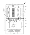
以下、図面を参照しながら本発明の除湿装置の実施の形態について説明する。図1は、本発明の実施の形態1に係る除湿装置の構成を示す模式図である。図1の除湿装置1は、筐体10と、圧縮機2、流路切換装置3、第1熱交換器4、減圧装置5及び第2熱交換器6が冷媒配管30で接続された冷媒回路とを有する。冷媒回路に流れる冷媒は、例えばR410A、HFC系冷媒、HC冷媒、CO2、NH3などの自然冷媒を適用することができる。CO2冷媒を適用する場合で、高圧が臨界圧力以上の運転の場合は、凝縮器は放熱器として動作する。
Hereinafter, embodiments of the dehumidifying device of the present invention will be described with reference to the drawings. FIG. 1 is a schematic diagram showing a configuration of a dehumidifying apparatus according to
筐体10は、箱状に形成されたものであって、内部には風路室10Aと機械室10Bとに区画する壁面11が設けられている。機械室10Bには圧縮機2及び流路切換装置3が配置され、風路室10Aには第1熱交換器4、減圧装置5及び第2熱交換器6が配置されている。壁面11には貫通穴が形成されており、冷媒配管30は貫通穴を貫通して流路切換装置3と第1熱交換器4及び流路切換装置3と第2熱交換器6とを接続する。なお、貫通穴と接続配管との隙間部分は気密に保つように構成することにより、壁面11の貫通穴と冷媒配管30との間の隙間を介して風路室10Aと機械室10Bとの間で気流が生じるのを防止することができる。
The
風路室10Aは、除湿対象空間の空気が流通するものであって、例えば矩形状に形成されている。風路室10Aは、除湿装置1の周囲にある除湿対象空間の空気を内部に導入する吸込口20aと、除湿された空気を外部に排出する吹出口20bとを有している。吸込口20a及び吹出口20bは例えば直線状に配置されており、風路室10A内に流通する空気は直線状に流れる。ここで、従来のようにデシカントロータを用いる場合、デシカントロータの吸着部と脱着部に空気を通風させる必要があり、曲がり部のある風路室10Aを構成せざるを得ない。風路室10Aに曲がり部があることにより、空気を搬送する際の圧力損失が大きくなってしまう。一方、図1の除湿装置1においては、風路ACが直線的に形成されていることにより、空気を搬送する際の圧力損失を小さくできる。よって、空気を搬送する送風機8の消費電力を少なくでき、より高効率の除湿装置1を提供することができる。
The
圧縮機2は、冷媒を吸入し圧縮して高温・高圧の状態にするものであり、例えば容量制御可能なインバータ圧縮機等で構成されている。流路切換装置3は、例えば四方弁からなっており、冷媒回路において冷媒が流れる流路を切り換えるものである。なお、図1において冷媒の流れが切り換えられる様子を実線方向と点線方向とで示す。
The
図1の実線の流路に切り換えられた場合、圧縮機2から吐出された冷媒が、流路切換装置3、第1熱交換器4、減圧装置5、第2熱交換器6及び流路切換装置3の順に流れて圧縮機2に戻る冷凍サイクルが構成される。この場合、第1熱交換器4は凝縮器(放熱器)として動作し、第2熱交換器6は蒸発器として動作する。一方、流路切換装置3の流路が図1の点線の流路に切り換えられた場合、圧縮機2から吐出された冷媒が、圧縮機2、流路切換装置3、第2熱交換器6、減圧装置5、第1熱交換器4及び流路切換装置3の順に流れて圧縮機2に戻る冷凍サイクルが構成される。この構成では、第2熱交換器6が凝縮器(放熱器)として動作し、第1熱交換器4は蒸発器として動作する。
When switched to the solid flow path in FIG. 1, the refrigerant discharged from the
第1熱交換器4及び第2熱交換器6は、それぞれ例えばプレートフィンチューブ熱交換器からなっており、伝熱管内を流れる冷媒とフィン周囲を流れる空気とを熱交換するものである。また、減圧装置5は、開度が可変である電子式膨張弁からなっている。デシカントブロック7は、デシカント材を固形で矩形に成型したものであり、例えばゼオライトやシリカゲル、高分子系吸着材など水分を吸脱着する材料で構成されている。そして、第1熱交換器4と第2熱交換器6とは筐体10の風路室10A内に設置されている。
Each of the first heat exchanger 4 and the second heat exchanger 6 includes, for example, a plate fin tube heat exchanger, and exchanges heat between the refrigerant flowing in the heat transfer tube and the air flowing around the fins. The
デシカントブロック7は、風路室10A内の第1熱交換器4と第2熱交換器6との間に不動の状態で固定されている。このため、デシカントブロック7を回転駆動するモーターやその固定構造等が不要であり、また、風路室10Aの構成をシンプルにすることができる。よって、除湿装置1のコンパクト化を図ることができ、装置構成を簡素にでき、低コストの装置とすることができる。
The desiccant block 7 is fixed in a stationary state between the first heat exchanger 4 and the second heat exchanger 6 in the
送風機8は、筐体10の風路室10A内に設けられ、除湿対象空間の空気を風路室10Aに流通させるものである。ここで、第1熱交換器4、デシカントブロック7、第2熱交換器6及び送風機8は、風路室10A内において直列に配置されている。送風機8の駆動により吸込口20aから風路AC内に吸入された空気は、第1熱交換器4、デシカントブロック7、第2熱交換器6、送風機8の順に直線状に流れた後、吹出口20bから除湿装置1の外部に排気される。この際、風路室10Aが矩形状に形成されているため、風路室10Aに実装される第1熱交換器4、第2熱交換器6及びデシカントブロック7のそれぞれが風路室10Aの形状に合わせて矩形の外形構造を採用することができ、風路室10A内に各構成要素を高密度に実装できる。
The
また、従来装置ではデシカントロータを用いることから、矩形状の風路ACの中に円形のロータを配置することになる。よって、ロータ配置部分では四隅にデッドスペースができてしまい、風路室10Aをコンパクトに構成できない。これに対し、本実施の形態1では、矩形のデシカントブロック7を用いることにより、デッドスペース無く配置することができ、高密度実装ができる。その結果、風路室10Aをコンパクトに構成することができる。
In addition, since a conventional apparatus uses a desiccant rotor, a circular rotor is disposed in a rectangular air passage AC. Therefore, dead spaces are formed at the four corners in the rotor arrangement portion, and the
さらに、従来の除湿装置において、吸着部と脱着部とはそれぞれ風路室を分ける必要があり、吸着部と脱着部の境界部分を気密に分離するシール構造が必要になる。これに対し、図1の除湿装置1においては、風路ACは1つであり、流路切換装置3の切り換えにより、デシカントブロック7の吸着と脱着を切り換えることができる。このため、従来のようにシール構造は不要であり、装置構成を簡略化でき、低コスト化を図ることができる。
Furthermore, in the conventional dehumidifying apparatus, it is necessary to divide the air passage chamber between the adsorbing portion and the desorbing portion, and a seal structure is required for hermetically separating the boundary portion between the adsorbing portion and the desorbing portion. On the other hand, in the
なお、風路ACに実装される第1熱交換器4、第2熱交換器6及びデシカントブロック7のそれぞれを、上述したように風路ACの形状に合わせて外形が矩形の構造とした場合、上述したようにコンパクト化の効果が得られるため好ましいが、必ずしも矩形に限定するものではない。 When each of the first heat exchanger 4, the second heat exchanger 6, and the desiccant block 7 mounted in the air path AC has a rectangular shape according to the shape of the air path AC as described above. As described above, it is preferable because the effect of downsizing can be obtained, but it is not necessarily limited to a rectangle.
さらに、除湿装置1は、風路室10A内の第1熱交換器4及び第2熱交換器6のそれぞれの下方に配置されたドレンパン40と、機械室10B内に設置され、ドレンパン40に配管41を介して接続されたドレンタンク42とを有している。ドレンパン40は、運転時に第1熱交換器4及び第2熱交換器6から滴下した発生したドレン水を受けるものである。ドレンパン40において受けたドレン水は図1の破線で示す配管41を経由して除湿装置1の最下部にあるドレンタンク42に流入し貯留される。
Further, the
次に、除湿装置1の除湿運転動作について説明する。除湿装置1では流路切換装置3の流路切り換えにより、第1運転モード及び第2運転モードの2つの運転モードが実現される。第1運転モードは、第2熱交換器6が凝縮器又は放熱器として動作すると共に、第1熱交換器4が蒸発器として動作し、デシカントブロック7が風路室10Aを通過する除湿対象空間の空気から水分を吸着する運転モードである。第2運転モードは、第2熱交換器6が蒸発器として動作すると共に、第1熱交換器4が凝縮器又は放熱器として動作し、デシカントブロック7に保持されている水分を脱着する運転モードである。
Next, the dehumidifying operation operation of the
(第1運転モード:冷凍サイクルの動作)
第1運転モードは、流路切換装置3の流路が図1の点線に切り換えられ、風路室10Aの上流側の第1熱交換器4が蒸発器になり、風路室10Aの下流側の第2熱交換器6が凝縮器になる運転モードである。まず、圧縮機2により低圧の冷媒が吸入された後に圧縮され、高温且つ高圧のガス冷媒になる。圧縮機2から吐出されたガス冷媒は、流路切換装置3を経て、第2熱交換器6に流入する。第2熱交換器6に流入した冷媒は、風路ACを流れる空気に放熱し空気を加熱しながら冷却されて凝縮し、高圧の液冷媒になって第2熱交換器6から流出する。第2熱交換器6から流出した液冷媒は、減圧装置5で減圧され、低圧の二相冷媒になる。その後、冷媒は第1熱交換器4に流入し、風路ACを流れる空気から吸熱し、空気を冷却しながら加熱されて蒸発し、低圧のガスになる。その後、冷媒は、流路切換装置3を経て圧縮機2に吸入される。
(First operation mode: operation of the refrigeration cycle)
In the first operation mode, the flow path of the flow
(第1運転モード:空気の動作)
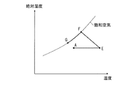
図2は図1の除湿装置における第1運転モード時の空気の状態変化を示す空気湿り線図である。なお、図2において、縦軸は空気の絶対湿度、横軸は空気の乾球温度、曲線は飽和空気を示しており、飽和空気における相対湿度は100%である。除湿装置1の除湿対象空間の空気(図2のA点)は、除湿装置1に流入後、第1熱交換器4において冷却される。冷媒回路は、第1熱交換器4内の冷媒温度が空気の露点温度よりも低くなるように運転されており、空気は第1熱交換器4により冷却されると共に除湿され、低温で高相対湿度の状態になる(図2のB点)。
(First operation mode: Air operation)
FIG. 2 is an air wetting diagram showing a change in the air state in the first operation mode in the dehumidifying device of FIG. In FIG. 2, the vertical axis represents the absolute humidity of the air, the horizontal axis represents the dry bulb temperature of the air, the curve represents the saturated air, and the relative humidity in the saturated air is 100%. The air (point A in FIG. 2) in the dehumidifying target space of the
その後、空気の相対湿度が高い空気はデシカントブロック7に流入し、デシカントブロック7に水分が吸着される。これにより、空気に含まれる水分量が減少し、更に除湿される。一方でデシカントブロック7に流入した空気は、吸着に伴い発生する吸着熱により加熱され、空気の温度は上昇し、高温且つ低湿度の状態になる(図2のC点)。その後、空気は第2熱交換器6に流入し、加熱されて高温になる(図2のD点)。そして、空気は送風機8に流入し、吹出口20bから除湿装置1外部に排気される。
Thereafter, the air having a high relative humidity flows into the desiccant block 7, and moisture is adsorbed by the desiccant block 7. As a result, the amount of water contained in the air is reduced and further dehumidified. On the other hand, the air flowing into the desiccant block 7 is heated by the heat of adsorption generated along with the adsorption, and the temperature of the air rises to a high temperature and low humidity state (point C in FIG. 2). Then, air flows into the 2nd heat exchanger 6, is heated, and becomes high temperature (D point of FIG. 2). Then, the air flows into the
(第2運転モード:冷凍サイクルの動作)
第2運転モードは、上流側の第1熱交換器4が凝縮器になり、下流側の第2熱交換器6が蒸発器になるように、流路切換装置3の流路が切り換えられた運転モードである。まず、圧縮機2により低圧のガスが吸入された後、圧縮され、高温且つ高圧のガスになる。圧縮機2より吐出された冷媒は、流路切換装置3を経て、第1熱交換器4に流入する。第1熱交換器4に流入した冷媒は、風路ACを流れる空気に放熱し、空気を加熱しながら冷却されて凝縮し、高圧の液冷媒になって第1熱交換器4から流出する。第1熱交換器4から流出した液冷媒は、減圧装置5で減圧され、低圧の二相冷媒になる。その後、冷媒は第2熱交換器6に流入し、風路ACを流れる空気より吸熱し、空気を冷却しながら冷媒そのものは加熱されて蒸発し、低圧のガスになる。そして、冷媒は、流路切換装置3を経て、圧縮機2に吸入される。
(Second operation mode: operation of the refrigeration cycle)
In the second operation mode, the flow path of the flow
(第2運転モード:空気の動作)
図3は図1の除湿装置における第2運転モード時の空気の状態変化を示す空気湿り線図である。なお、図3において、縦軸は空気の絶対湿度、横軸は空気の乾球温度であり、図3の曲線は飽和空気を示すもので、飽和空気における相対湿度は100%である。除湿装置1の除湿対象空間の空気(図3のA点)は、除湿装置1に流入後、第1熱交換器4において加熱され、温度が上昇すると共に、相対湿度が低下する(図3のE点)。
(Second operation mode: air operation)
FIG. 3 is an air wetting diagram illustrating a change in the air state in the second operation mode in the dehumidifying device of FIG. 1. In FIG. 3, the vertical axis represents the absolute humidity of air, the horizontal axis represents the dry bulb temperature of air, the curve in FIG. 3 represents saturated air, and the relative humidity in saturated air is 100%. The air in the dehumidifying target space of the dehumidifying device 1 (point A in FIG. 3) flows into the
その後、空気はデシカントブロック7に流入するが、空気の相対湿度が低いため、デシカントブロック7に保持されている水分は脱着(放出)され、空気に含まれる水分量が増加する。一方でデシカントブロック7に流入した空気から、脱着に伴う脱着熱が奪われ、空気の温度は低下し、低温且つ高湿度の状態になる(図3のF点)。その後、空気は第2熱交換器6に流入し、冷却される。なお、冷媒回路は、第2熱交換器6内の冷媒温度が空気の露点温度よりも低くなるように運転されており、空気は第2熱交換器6により冷却されると共に除湿され、低温で絶対湿度の低い状態になる(図3のG点)。その後、空気は送風機8に流入し、吹出口20bから除湿装置1外部に排気される。
Thereafter, air flows into the desiccant block 7, but since the relative humidity of the air is low, the moisture held in the desiccant block 7 is desorbed (released), and the amount of moisture contained in the air increases. On the other hand, desorption heat accompanying desorption is deprived from the air flowing into the desiccant block 7, the temperature of the air is lowered, and the temperature becomes low and high humidity (point F in FIG. 3). Thereafter, the air flows into the second heat exchanger 6 and is cooled. The refrigerant circuit is operated such that the refrigerant temperature in the second heat exchanger 6 is lower than the dew point temperature of the air, and the air is cooled and dehumidified by the second heat exchanger 6 at a low temperature. The absolute humidity is low (point G in FIG. 3). Thereafter, the air flows into the
以上のように、第2運転モードでは第1運転モードと比べて高湿な空気が蒸発器として機能する第2熱交換器6に流入するため、多くの結露を発生することで結露水としての除湿量を増加することができる。一方、第1運転モードでは、第1熱交換器4における冷媒での冷却による除湿に加えて、デシカントブロック7の吸着による除湿も実施される。よって、第1運転モードは第2運転モードに比べて吹き出し空気の絶対湿度を低下させることができる。 As described above, in the second operation mode, air that is humid compared to the first operation mode flows into the second heat exchanger 6 that functions as an evaporator, so that a large amount of dew condensation is generated to generate dew condensation water. The amount of dehumidification can be increased. On the other hand, in the first operation mode, dehumidification by adsorption of the desiccant block 7 is performed in addition to dehumidification by cooling with the refrigerant in the first heat exchanger 4. Therefore, the 1st operation mode can reduce the absolute humidity of blowing air compared with the 2nd operation mode.
上述した第1運転モード及び第2運転モードの切り換えは、制御装置60により行われる。具体的には、除湿装置1は、風路室10Aに設置され、除湿対象空間の空気の相対湿度を検知する湿度検知部50と、湿度検知部50において検知された相対湿度を用いて上述した運転モードを制御する制御装置60とを備えている。
Switching between the first operation mode and the second operation mode described above is performed by the
湿度検知部50は、例えば吸込口20aに設置されており、吸込口20aから吸い込まれる除湿対象空間の空気の相対湿度を計測する。なお、湿度検知部50の設置場所は吸込口20aに限られず、第1熱交換器4の通過後、デシカントブロック7の通過後、第2熱交換器6の通過後の空気が通過する風路室内もしくは吹出口20b周辺以外の風路室10A内部、筐体10の表面に湿度検知部50を取り付けてもよい。また、湿度検知部50は、除湿対象空間の空気の相対湿度を推算できる装置であればよく、例えば吸込空気の相対湿度を吸込空気の状態から検知してもよい。あるいは、湿度検知部50は、露点温度を計測するセンサからなり、露点温度から相対湿度を推算するなどの手法を採用してもよい。
The
さらに、湿度検知部50は、除湿対象空間に設置され、制御装置60が温湿度情報を有線もしくは無線通信によって相対湿度の情報を得てもよいし、使用者が室内湿度を入力する入力部からなってもよい。あるいは、湿度検知部50は、前回の運転終了時の温湿度情報から温湿度情報を記憶し、運転再開時の判定に利用してもよい。この場合、空気側から相対湿度を直接検知する必要がないため、コスト低減及び吸込口20aのセンサスペース削減からコンパクト化することができる。
Further, the
制御装置60は、例えばマイクロコンピュータで構成され、CPU、RAM及びROM等を備えており、ROMには制御プログラムが記憶されている。制御装置60は、流路切換装置3の切り換え等の冷媒回路の運転の制御、送風機8の回転数制御、圧縮機2の回転数制御、減圧装置5の開度制御等の各種制御を行うものである。
The
制御装置60は、運転開始時に湿度検知部50において検知された相対湿度が設定湿度閾値href以上であるか否かを判定する湿度判定部61と、湿度判定部61の判定結果に基づいて、第1運転モードもしくは第2運転モードのうち、いずれの運転モードで運転を開始するかを制御する運転制御部62とを有している。
Based on the determination result of the
湿度判定部61には、予め設定湿度閾値hrefが記憶されており、設定湿度閾値hrefは例えば相対湿度50%よりも大きい値に設定されている。そして、運転制御部62は、湿度判定部61において相対湿度が設定湿度閾値href未満であると判定された場合、運転制御部62は第1運転モードで運転を開始する。一方、湿度判定部61において相対湿度が設定湿度閾値href以上であると判定された場合、運転制御部62は第2運転モードで運転を開始する。
The
運転開始時のデシカントブロック7の状態は、除湿対象空間の空気の相対湿度に依存した状態になっている。言い換えれば、除湿対象空間の空気の相対湿度は運転開始時のデシカントブロック7の水分保持量を表している。そこで、湿度判定部61は運転開始時のデシカントブロック7の水分保持量に合わせて第1運転モードと第2運転モードのうち、いずれの運転モードが適しているかを閾値処理により判定する。そして、運転制御部62は除湿能力の立ち上がりが早くなる運転モードを選択して運転を開始する。
The state of the desiccant block 7 at the start of operation depends on the relative humidity of the air in the dehumidification target space. In other words, the relative humidity of the air in the dehumidifying target space represents the moisture retention amount of the desiccant block 7 at the start of operation. Therefore, the
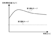
具体的には、図4は除湿対象空間の空気の相対湿度が高い場合の第1運転モード及び第2運転モードによる除湿量変動を示したグラフである。図4に示すように、除湿対象空間の空気が高湿である場合、運転開始時のデシカントブロック7の保持水分量は多くなる。デシカントブロック7の水分保持量が多い状態で第1運転モードが選択された場合、図4の実線に示すように、デシカントブロック7において吸着反応が発生しにくくなり、主に第1熱交換器4による冷却除湿分のみが除湿量になる。 Specifically, FIG. 4 is a graph showing dehumidification amount fluctuations in the first operation mode and the second operation mode when the relative humidity of the air in the dehumidification target space is high. As shown in FIG. 4, when the air in the dehumidification target space is highly humid, the amount of moisture retained in the desiccant block 7 at the start of operation increases. When the first operation mode is selected in a state where the moisture retention amount of the desiccant block 7 is large, as shown by the solid line in FIG. 4, the adsorption reaction is less likely to occur in the desiccant block 7 and mainly the first heat exchanger 4. Only the cooling dehumidification due to is the dehumidification amount.
そこで、運転制御部62は、運転開始時の除湿対象空間の空気が高湿である場合には、第2運転モードで運転を開始するように制御する。すると、図4の点線で示すように、運転開始時からデシカントブロック7の脱着反応により第2熱交換器6に流入する空気が高湿化し、第2熱交換器6において結露として発生する除湿量が増加する。このため、除湿装置1の起動時の除湿能力を増加させることができ、運転開始時からの除湿能力の立ち上げを早期に行うことができる。その後、運転制御部62が第2運転モードから第1運転モードに切り換えた際には、図4の点線に示すように、デシカントブロック7の吸着反応により吹き出し空気の絶対湿度を低下させることができる。
Therefore, the
図5は除湿対象空間の空気の相対湿度が低湿である場合の第1運転モード及び第2運転モードによる除湿量変動を示したグラフである。除湿対象空間の空気の相対湿度が低い場合、デシカントブロック7の保持水分量は少なくなる。デシカントブロック7の水分保持量が少ない状態で第2運転モードが選択された場合、図5の点線に示すように脱着反応が発生しにくく、主に第2熱交換器6による冷却除湿分のみが除湿量になる。 FIG. 5 is a graph showing dehumidification amount fluctuations in the first operation mode and the second operation mode when the relative humidity of the air in the dehumidification target space is low. When the relative humidity of the air in the dehumidifying target space is low, the amount of moisture retained in the desiccant block 7 is reduced. When the second operation mode is selected in a state where the moisture retention amount of the desiccant block 7 is small, as shown by the dotted line in FIG. 5, the desorption reaction hardly occurs, and only the cooling dehumidification by the second heat exchanger 6 mainly occurs. Dehumidification amount.
そこで、運転制御部62は、運転開始時の除湿対象空間の空気が低湿である場合には、第1運転モードで運転を開始するように制御する。これにより、図5の実線に示すように、除湿装置1の除湿量は、第2熱交換器6での結露発生量のみならずデシカントブロック7の吸着反応による除湿を加えたものになる。このため、除湿装置1の起動時の除湿能力を増加させることができ、運転開始時からの除湿能力の立ち上げを早期に行うことができる。その後、運転制御部62が第1運転モードから第2運転モードに切り換えた際には、デシカントブロック7の脱着反応から、第2熱交換器6に流入する空気が高湿化するために結露として発生する除湿量を増加し、運転開始時の除湿能力を増加させることができる。
Therefore, the
なお、除湿対象空間の空気の湿度が中程度である場合、第1運転モードもしくは第2運転モードのいずれであってもデシカントブロック7の吸着反応もしくは脱着反応のどちらかが発生し、ある程度除湿することができる。このような状況ではどちらのモードで運転開始しても通常よりも早期にデシカントブロック7が飽和する。このため、通常運転時と比較すると、デシカントブロック7が反応しない時間が発生しやすくなる。 When the humidity of the air in the dehumidification target space is medium, either the adsorption reaction or desorption reaction of the desiccant block 7 occurs in either the first operation mode or the second operation mode, and the dehumidification is performed to some extent. be able to. In such a situation, the desiccant block 7 is saturated earlier than usual regardless of which mode is started. For this reason, compared with the time of a normal driving | operation, the time when the desiccant block 7 does not react becomes easy to generate | occur | produce.
図6はデシカントブロック7が反応していない状態での第1運転モードと第2運転モードの除湿量の比較を示すグラフである。図6において、第1運転モードと第2運転モードを比較すると、第1運転モードは除湿対象空間の空気が蒸発器として機能する第1熱交換器4に流入し、冷却除湿される。一方、第2運転モードでは除湿対象空間の空気温度が凝縮器として機能する第1熱交換器4に加熱されたのちに蒸発器として機能する第2熱交換器6に流入する。このため、第2運転モードにおいては除湿対象空間の空気よりも高温の空気を除湿することになる。よって、図6の点線に示すように、第2運転モードの除湿量は第1運転モードの除湿量よりも低い。したがって、除湿対象空間の空気の湿度が中程度である場合には、第1運転モードで運転が開始されることが好ましい。 FIG. 6 is a graph showing a comparison of the dehumidification amount between the first operation mode and the second operation mode when the desiccant block 7 is not reacted. In FIG. 6, when the first operation mode and the second operation mode are compared, in the first operation mode, the air in the dehumidification target space flows into the first heat exchanger 4 functioning as an evaporator and is cooled and dehumidified. On the other hand, in the second operation mode, the air temperature in the dehumidifying target space is heated by the first heat exchanger 4 that functions as a condenser and then flows into the second heat exchanger 6 that functions as an evaporator. For this reason, in the second operation mode, air having a temperature higher than that of the air in the dehumidifying target space is dehumidified. Therefore, as shown by the dotted line in FIG. 6, the dehumidification amount in the second operation mode is lower than the dehumidification amount in the first operation mode. Therefore, when the humidity of the air in the dehumidifying target space is medium, it is preferable to start the operation in the first operation mode.
このように、除湿対象空間の空気の相対湿度が中湿度及び高湿度である場合には第2運転モードで運転が開始され、低湿度である場合には第1運転モードで運転が開始されることが望ましい。以上の事項を考慮し、湿度判定部61における設定湿度閾値hrefは、相対湿度50%以上の値に設定されている。
Thus, when the relative humidity of the air in the dehumidifying target space is medium humidity and high humidity, the operation is started in the second operation mode, and when the relative humidity is low, the operation is started in the first operation mode. It is desirable. Considering the above matters, the set humidity threshold value href in the
図7は、除湿対象空間の空気の相対湿度と起動時の運転モードの関係を示したグラフである。図7に示すように、運転起動時の運転モードの選択では第1運転モードを選択する相対湿度幅の方が、第2運転モードを選択する相対湿度幅よりも大きい。したがって、例えば設定湿度閾値hrefが50%に設定され、相対湿度が50%以上の場合に第2運転モードで起動する。なお、設定湿度閾値hrefは50%以上であればよく、たとえば、起動初期の相対湿度が70%未満であれば第1運転モードで運転を開始し、70%以上であれば第2運転モードで運転を開始してもよい。 FIG. 7 is a graph showing the relationship between the relative humidity of the air in the dehumidification target space and the operation mode at startup. As shown in FIG. 7, in the selection of the operation mode at the start of operation, the relative humidity range for selecting the first operation mode is larger than the relative humidity range for selecting the second operation mode. Therefore, for example, when the set humidity threshold href is set to 50% and the relative humidity is 50% or more, the second operation mode is started. The set humidity threshold value href may be 50% or more. For example, if the relative humidity at the initial stage of startup is less than 70%, the operation is started in the first operation mode, and if it is 70% or more, the operation is started in the second operation mode. Operation may be started.
また、運転制御部62は、第1運転モードもしくは第2運転モードにより運転が開始された後において、第1運転モードと第2運転モードとを交互に繰り返すように流路切換装置3を制御する。例えば第1運転モードが一定以上の時間の間継続して実施した場合、デシカントブロック7に含まれる水分量には上限があるため、一定以上の時間の間運転すると、デシカントブロック7に水分が吸着されなくなり除湿量が低下する。そこで、制御装置60は、デシカントブロック7の保持水分量が上限近くになった段階で、第2運転モードに切り換え、デシカントブロック7から水分を放出する運転を実施する。また、制御装置60は、第2運転モードをしばらく実施し、デシカントブロック7の保持水分量が適度に減少した時点で再び第1運転モードに切り換える。このように、第1運転モードと第2運転モードとを交互に実施することにより、デシカントブロック7の吸脱着作用が順次行われるため、デシカントの吸脱着作用による除湿量増加効果が維持される。
Further, the
図8は図1の除湿装置の動作例を示すフローチャートであり、図1から図8を参照して除湿装置1の動作例について説明する。まず、除湿装置1へ運転開始の指示がなされたとき(ステップST1)、湿度検知部50により除湿対象空間の空気の相対湿度が検知される(ステップST2)。その後、制御装置60の湿度判定部61において、除湿対象空間の空気の相対湿度が設定湿度閾値href以上であるか否かが判定される(ステップST3)。
FIG. 8 is a flowchart showing an operation example of the dehumidifying apparatus in FIG. 1, and an operation example of the
相対湿度が設定湿度閾値href以上であると判定された場合(ステップST3のYES)、第1熱交換器4が凝縮器になり第2熱交換器6が蒸発器になる第2運転モードで運転が開始される(ステップST4)。すると、第1熱交換器4による冷却除湿及びデシカントブロック7の吸着による除湿運転が運転開始時から実行される。一方、相対湿度が設定湿度閾値href未満であると判定された場合(ステップST3のNO)、第1熱交換器4が蒸発器になり、風路室10Aの下流側の第2熱交換器6が凝縮器になる第1運転モードで運転が開始される(ステップST5)。すると、第1熱交換器4による冷却除湿及びデシカントブロック7の吸着による除湿が運転開始から行われる。第1運転モードもしくは第2運転モードで運転が開始されてから一定時間経過した後には、運転制御部62において運転モードが切り換えられる(ステップST6)。
When it is determined that the relative humidity is equal to or higher than the set humidity threshold value href (YES in step ST3), the operation is performed in the second operation mode in which the first heat exchanger 4 is a condenser and the second heat exchanger 6 is an evaporator. Is started (step ST4). Then, cooling dehumidification by the first heat exchanger 4 and dehumidification operation by adsorption of the desiccant block 7 are executed from the start of operation. On the other hand, when it is determined that the relative humidity is less than the set humidity threshold value href (NO in step ST3), the first heat exchanger 4 becomes an evaporator and the second heat exchanger 6 on the downstream side of the
上記実施の形態1によれば、運転制御部62において除湿対象空間の湿度に応じて運転開始時の運転モードを選択することにより、運転開始時の除湿量が増加し、室内湿度を早期に目標湿度に到達させることができる。すなわち、運転開始時の運転モードが第1運転モードもしくは第2運転モードのいずれか一方に予め設定されているとき、運転開始時のデシカントブロック7の水分保持量によっては、運転開始時から早期に除湿能力を発揮することができない場合がある。そこで、湿度判定部61が相対湿度に基づいてデシカントブロック7の状態を把握し、運転制御部62がデシカントブロック7の状態に合った第1運転モードもしくは第2運転モードで運転を開始する。これにより、デシカントブロック7における除湿が運転の立ち上がりから早期に実施されることになるため、除湿能力の立ち上がりを早くすることができる。
According to the first embodiment, the
また、設定湿度閾値hrefが、50%以上の相対湿度である場合、除湿対象空間の相対湿度が高湿の場合のみならず中湿のときにも第1運転モードで運転を開始して、運転開始時の除湿能力を早期に立ち上げることができる。 In addition, when the set humidity threshold value href is 50% or more relative humidity, the operation is started in the first operation mode not only when the relative humidity of the dehumidifying target space is high but also when the humidity is medium. The dehumidifying ability at the start can be started early.
実施の形態2.
図9は本発明の実施の形態2に係る除湿装置の構成を示す模式図であり、図9を参照して除湿装置100について説明する。なお、図9の除湿装置100において図1の除湿装置1と同一の構成を有する部位には同一の構成を付してその説明を省略する。図9の除湿装置200が図1の除湿装置1と異なる点は、湿度検知部の構成である。
FIG. 9 is a schematic diagram showing the configuration of the dehumidifying apparatus according to
図9の除湿装置100において、湿度検知部は、第1熱交換器4を流れる冷媒の温度を検知する冷媒温度センサ151と、第1熱交換器4を通過した後の空気の温度を検知する空気温度センサ152とを有している。ここで、運転制御部62が蒸発器を通過する冷媒の過熱度を減圧装置5を用いて制御している状況において、相対湿度が高い場合には蒸発器を通過した空気の温度と冷媒の蒸発温度との差が小さくなる特性がある。そこで、湿度判定部61は、第1熱交換器4の蒸発温度と、第1熱交換器4を通過した後の空気温度との差分から相対湿度を演算する。
In the
ここで、上述した冷媒温度及び空気温度は、冷媒回路が起動した後にしか検知することができないため、運転制御部62は、最初に第1熱交換器4は蒸発器になり第2熱交換器6は凝縮器になる第1運転モードで湿度を検出するための試運転を開始する。その後、第1熱交換器4の蒸発温度と、第1熱交換器4を通過した後の空気温度との差分から相対湿度を演算する。そして、演算した相対湿度が設定湿度閾値href以下の場合には第1運転モードを継続し、設定湿度閾値hrefよりも大きい場合には第2運転モードに切り換え、除湿のための運転を開始するようにしてもよい。
Here, since the refrigerant temperature and the air temperature described above can be detected only after the refrigerant circuit is activated, the
なお、冷媒温度センサ151は、冷媒の温度を検知するものであればその構成を問わず、例えば第1熱交換器の冷媒配管温度、第1熱交換器の熱交換器フィン温度、第1熱交換器を通過する冷媒の圧力換算した飽和温度、冷媒配管内を通過する冷媒の温度を計測した冷媒温度のうち少なくとも1つ以上を冷媒温度として検出するものであればよい。
The
上記実施の形態2によれば、湿度検知部は、冷媒回路側から相対湿度を検知することにより、相対湿度を直接計測しなくとも、除湿対象空間の空気の相対湿度を検知することができるため、除湿対象空間にセンサを設置する必要がなくなる。そして、冷媒回路を制御するために冷媒温度センサ151及び空気温度センサ152を流用して相対湿度の検知を行うことができるため、構成の簡略化を図ることができる。また、実施の形態2の場合であっても、実施の形態1と同様、相対湿度に基づいて運転開始時の運転モードを設定することにより、運転開始時の除湿能力を増大させることができる。
According to the second embodiment, the humidity detection unit can detect the relative humidity of the air in the dehumidification target space without directly measuring the relative humidity by detecting the relative humidity from the refrigerant circuit side. This eliminates the need to install a sensor in the dehumidified space. Since the
実施の形態3.
図10は本発明の実施の形態3に係る除湿装置の構成を示す模式図であり、図10を参照して除湿装置200について説明する。なお、図10の除湿装置200において図1の除湿装置1と同一の構成を有する部位には同一の構成を付してその説明を省略する。図9の除湿装置200が図1の除湿装置1と異なる点は、冷媒回路が第3熱交換器201を有する点である。
FIG. 10 is a schematic diagram showing the configuration of the dehumidifying apparatus according to
図10の冷媒回路は、第1熱交換器4及び第2熱交換器6に加えて、第3熱交換器201を有している。第3熱交換器201は、風路室10A内の第2熱交換器6の下流に配置されており、一方が圧縮機2の吐出側に接続されており、他方が流路切換装置3の流入側に接続されている。そして、第1運転モード時には、圧縮機2、第3熱交換器201、流路切換装置3、第2熱交換器6、減圧装置5、第1熱交換器4、流路切換装置3、圧縮機2の順で冷媒が流れる冷媒回路が形成される。第2運転モード時には、圧縮機2、第3熱交換器201、流路切換装置3、第1熱交換器4、減圧装置5、第2熱交換器6、流路切換装置3、圧縮機2の順で冷媒が流れる冷媒回路が形成される。
The refrigerant circuit of FIG. 10 includes a
第3熱交換器201において凝縮熱が放熱されることにより、第2運転モード時にデシカントブロック7に流入する空気温度を制御することができる。よって、デシカントブロック7における脱着反応速度を鈍化させることができる。一方、高湿条件では、蒸発器として機能する第2熱交換器6の除湿能力以上に高湿空気が通過することがある。そこで、そのような場合に脱着速度を鈍化することで、除湿しきれない状況を回避することができ、結露として回収できる除湿量を増加させることができる。また、実施の形態3の場合であっても、実施の形態1と同様、相対湿度に基づいて運転開始時の運転モードを設定することにより、運転開始時の除湿能力を増大させることができる。
When the heat of condensation is dissipated in the
なお、図10の除湿装置200において、湿度検知部50は吸込口20aに設けられている場合について例示しているが、実施の形態2のように、冷媒回路から相対湿度を検知するものであってもよい。
In the
本発明の除湿装置の実施の形態は、上記実施の形態に限定されるものではなく、本発明の要旨を逸脱しない範囲で例えば以下のように種々変形実施可能である。例えば、第1運転モードと第2運転モードのそれぞれの運転時間は、予め定められた時間としてもよいが、各運転モードのそれぞれの運転時間には、空気条件や除湿装置1の運転状態に応じた適正値がある。よって、その適正値で運転できるように、空気条件や除湿装置1の運転状態に基づいて各運転モードの運転時間を決定するようにしてもよい。
Embodiments of the dehumidifying device of the present invention are not limited to the above-described embodiments, and various modifications can be made as follows, for example, without departing from the gist of the present invention. For example, each operation time in the first operation mode and the second operation mode may be a predetermined time, but each operation time in each operation mode depends on the air condition and the operation state of the
また、本実施の形態の第1運転モードでは、搬送される空気に対し、第1熱交換器4による除湿、デシカントブロック7による除湿に次いで、第2熱交換器6による加熱が実施される。そのため、除湿装置1の吹出空気は、高温で水分量の少ない状態になり(図3、G点)、相対湿度を例えば20%以下の低相対湿度にできる。このような低相対湿度の空気は、乾燥用途に好適な空気であり、この空気を、洗濯物などの被乾燥物に直接当てるようにしてもよい。これにより、被乾燥物の乾燥を促進することができ、より高性能な乾燥機能を実現することができる。
Moreover, in the 1st operation mode of this Embodiment, the heating by the 2nd heat exchanger 6 is implemented following the dehumidification by the 1st heat exchanger 4 and the dehumidification by the desiccant block 7 with respect to the conveyed air. Therefore, the blown air of the
除湿装置1が被乾燥物の乾燥に用いられる場合、第2運転モードでの吹出空気は、第1運転モードでの吹出空気に比べて低温で高湿度であるため、第2運転モードのときのみ、吹出空気を被乾燥物に当てることが望ましい。よって、このような用途に対応するため、除湿装置1の吹出口20bに、吹出風向を変更するベーンが設けられてもよい。そして、ベーンは、第1運転モードでの吹出方向と第2運転モードでの吹出方向とを別の方向に調整する機能を有し、第2運転モードのときのみ、吹出口20bからの吹出空気が被乾燥物にあたるようにベーンを調整してもよい。これにより、被乾燥物の乾燥をより促進でき、高性能な乾燥機能を実現できる。
When the
1、100、200 除湿装置、2 圧縮機、3 流路切換装置、4 第1熱交換器、5 減圧装置、6 第2熱交換器、7 デシカントブロック、8 送風機、10 筐体、10A 風路室、10B 機械室、11 壁面、20a 吸込口、20b 吹出口、30 冷媒配管、40 ドレンパン、41 配管、42 ドレンタンク、50 湿度検知部、60 制御装置、61 湿度判定部、62 運転制御部、151 冷媒温度センサ、152 空気温度センサ、201 第3熱交換器、AC 風路、href 設定湿度閾値。 1, 100, 200 Dehumidifier, 2 Compressor, 3 Flow switching device, 4 First heat exchanger, 5 Depressurizer, 6 Second heat exchanger, 7 Desiccant block, 8 Blower, 10 Housing, 10A Air passage Chamber, 10B machine room, 11 wall surface, 20a inlet, 20b outlet, 30 refrigerant piping, 40 drain pan, 41 piping, 42 drain tank, 50 humidity detection unit, 60 control device, 61 humidity determination unit, 62 operation control unit, 151 refrigerant temperature sensor, 152 air temperature sensor, 201 3rd heat exchanger, AC air path, href set humidity threshold.
Claims (8)
除湿対象空間の空気が流通する風路室が形成され、前記風路室内に前記第1熱交換器と前記第2熱交換器とが設置されている筐体と、
前記風路室内の前記第1熱交換器と前記第2熱交換器との間に配置され、水分の吸脱着を行うデシカントブロックと、
前記筐体の風路室内に設けられ、除湿対象空間の空気を前記風路室に流通させる送風機と、
前記筐体に設置され、除湿対象空間の空気の湿度を検知する湿度検知部と、
前記湿度検知部において検知された空気の湿度に基づいて、前記冷媒回路の動作を制御する制御装置と
を有し、
前記制御装置は、
運転開始時に前記湿度検知部において検知された相対湿度が設定湿度閾値以上であるか否かを判定する湿度判定部と、
前記第2熱交換器が凝縮器又は放熱器として動作すると共に、前記第1熱交換器が蒸発器として動作し、前記デシカントブロックが前記風路室を通過する除湿対象空間の空気から水分を吸着する第1運転モードと、前記第2熱交換器が蒸発器として動作すると共に、前記第1熱交換器が凝縮器又は放熱器として動作し、前記デシカントブロックに保持されている水分を脱着する第2運転モードとを、前記湿度判定部の判定結果に基づいて切り換えるように、前記冷媒回路を制御する運転制御部と、
を備え、
前記運転制御部は、前記湿度判定部において相対湿度が設定湿度閾値未満であると判定された場合には前記第1運転モードで運転を開始し、相対湿度が前記設定湿度閾値以上であると判定された場合には前記第2運転モードで運転を開始するものである除湿装置。 A refrigerant circuit in which a compressor, a flow path switching device, a first heat exchanger, a decompression unit, and a second heat exchanger are connected using refrigerant piping;
A housing in which an air passage chamber through which air in the dehumidification target space flows is formed, and the first heat exchanger and the second heat exchanger are installed in the air passage chamber,
A desiccant block that is disposed between the first heat exchanger and the second heat exchanger in the air passage chamber and performs moisture adsorption and desorption;
A blower that is provided in the air passage chamber of the housing and distributes the air in the dehumidification target space to the air passage chamber;
A humidity detector that is installed in the housing and detects the humidity of the air in the dehumidification target space;
A controller for controlling the operation of the refrigerant circuit based on the humidity of the air detected by the humidity detector;
The control device includes:
A humidity determination unit that determines whether the relative humidity detected by the humidity detection unit at the start of operation is equal to or higher than a set humidity threshold;
The second heat exchanger operates as a condenser or a radiator, the first heat exchanger operates as an evaporator, and the desiccant block absorbs moisture from the air in the dehumidifying target space passing through the air passage chamber. A first operation mode, and the second heat exchanger operates as an evaporator, and the first heat exchanger operates as a condenser or a radiator, and desorbs moisture held in the desiccant block. An operation control unit that controls the refrigerant circuit so as to switch between two operation modes based on a determination result of the humidity determination unit;
With
The operation control unit starts operation in the first operation mode when the humidity determination unit determines that the relative humidity is less than the set humidity threshold, and determines that the relative humidity is equal to or greater than the set humidity threshold. A dehumidifier that starts operation in the second operation mode when the operation is performed.
前記第1熱交換器を流れる冷媒の温度を検知する冷媒温度センサと
前記第1熱交換器を通過した後の空気の温度を検知する空気温度センサと、
を有し、
前記湿度判定部は、前記空気温度センサより得られる空気の温度と前記冷媒温度センサより得られる前記第1熱交換器の冷媒温度との差分が設定差分閾値よりも小さい場合、除湿対象空間の空気の湿度が設定湿度閾値以上であると判定するものである請求項1〜3のいずれか1項に記載の除湿装置。 The humidity detector is
A refrigerant temperature sensor for detecting the temperature of the refrigerant flowing through the first heat exchanger; an air temperature sensor for detecting the temperature of air after passing through the first heat exchanger;
Have
When the difference between the temperature of the air obtained from the air temperature sensor and the refrigerant temperature of the first heat exchanger obtained from the refrigerant temperature sensor is smaller than a set difference threshold, the humidity determination unit The dehumidifier according to any one of claims 1 to 3, wherein the humidity is determined to be equal to or higher than a set humidity threshold.
Priority Applications (1)
| Application Number | Priority Date | Filing Date | Title |
|---|---|---|---|
| JP2015023469A JP6021965B2 (en) | 2015-02-09 | 2015-02-09 | Dehumidifier |
Applications Claiming Priority (1)
| Application Number | Priority Date | Filing Date | Title |
|---|---|---|---|
| JP2015023469A JP6021965B2 (en) | 2015-02-09 | 2015-02-09 | Dehumidifier |
Publications (2)
| Publication Number | Publication Date |
|---|---|
| JP2016144789A JP2016144789A (en) | 2016-08-12 |
| JP6021965B2 true JP6021965B2 (en) | 2016-11-09 |
Family
ID=56685221
Family Applications (1)
| Application Number | Title | Priority Date | Filing Date |
|---|---|---|---|
| JP2015023469A Active JP6021965B2 (en) | 2015-02-09 | 2015-02-09 | Dehumidifier |
Country Status (1)
| Country | Link |
|---|---|
| JP (1) | JP6021965B2 (en) |
Cited By (1)
| Publication number | Priority date | Publication date | Assignee | Title |
|---|---|---|---|---|
| JP7158472B2 (en) | 2017-10-04 | 2022-10-21 | オーアンドエム ハリヤード インターナショナル アンリミテッド カンパニー | Method and system for pleating textile products on a manufacturing line |
Family Cites Families (3)
| Publication number | Priority date | Publication date | Assignee | Title |
|---|---|---|---|---|
| JP4649967B2 (en) * | 2004-12-01 | 2011-03-16 | パナソニック株式会社 | Dehumidifier |
| JP5452565B2 (en) * | 2011-10-27 | 2014-03-26 | 三菱電機株式会社 | Dehumidifier |
| JP5854917B2 (en) * | 2012-04-26 | 2016-02-09 | 三菱電機株式会社 | Air conditioner |
-
2015
- 2015-02-09 JP JP2015023469A patent/JP6021965B2/en active Active
Cited By (1)
| Publication number | Priority date | Publication date | Assignee | Title |
|---|---|---|---|---|
| JP7158472B2 (en) | 2017-10-04 | 2022-10-21 | オーアンドエム ハリヤード インターナショナル アンリミテッド カンパニー | Method and system for pleating textile products on a manufacturing line |
Also Published As
| Publication number | Publication date |
|---|---|
| JP2016144789A (en) | 2016-08-12 |
Similar Documents
| Publication | Publication Date | Title |
|---|---|---|
| JP5452565B2 (en) | Dehumidifier | |
| JP6029750B2 (en) | Dehumidifier | |
| AU2013387943B2 (en) | Dehumidifier | |
| CN106573195B (en) | Dehumidifying device | |
| US20170205089A1 (en) | Dehumidifier | |
| JP6138336B2 (en) | Air conditioner and control method of air conditioner | |
| JP6338765B2 (en) | Dehumidifier | |
| JP6138335B2 (en) | Air conditioner | |
| JP6108928B2 (en) | Air conditioner | |
| JP6037926B2 (en) | Air conditioner | |
| JP6141508B2 (en) | Air conditioner and control method of air conditioner | |
| JP6021965B2 (en) | Dehumidifier | |
| JP6664413B2 (en) | Dehumidifier | |
| JP7126611B2 (en) | air conditioner | |
| JP7233538B2 (en) | air conditioner | |
| JP2017101917A (en) | Air conditioner | |
| JP2007192436A (en) | Air conditioner | |
| WO2015136653A1 (en) | Dehumidifying apparatus |
Legal Events
| Date | Code | Title | Description |
|---|---|---|---|
| TRDD | Decision of grant or rejection written | ||
| A01 | Written decision to grant a patent or to grant a registration (utility model) |
Free format text: JAPANESE INTERMEDIATE CODE: A01 Effective date: 20160906 |
|
| A61 | First payment of annual fees (during grant procedure) |
Free format text: JAPANESE INTERMEDIATE CODE: A61 Effective date: 20161004 |
|
| R150 | Certificate of patent or registration of utility model |
Ref document number: 6021965 Country of ref document: JP Free format text: JAPANESE INTERMEDIATE CODE: R150 |
|
| R250 | Receipt of annual fees |
Free format text: JAPANESE INTERMEDIATE CODE: R250 |
|
| R250 | Receipt of annual fees |
Free format text: JAPANESE INTERMEDIATE CODE: R250 |
|
| R250 | Receipt of annual fees |
Free format text: JAPANESE INTERMEDIATE CODE: R250 |
|
| R250 | Receipt of annual fees |
Free format text: JAPANESE INTERMEDIATE CODE: R250 |
|
| R250 | Receipt of annual fees |
Free format text: JAPANESE INTERMEDIATE CODE: R250 |