JP6021865B2 - Sheet discharging apparatus and image forming apparatus having the same - Google Patents
Sheet discharging apparatus and image forming apparatus having the same Download PDFInfo
- Publication number
- JP6021865B2 JP6021865B2 JP2014177957A JP2014177957A JP6021865B2 JP 6021865 B2 JP6021865 B2 JP 6021865B2 JP 2014177957 A JP2014177957 A JP 2014177957A JP 2014177957 A JP2014177957 A JP 2014177957A JP 6021865 B2 JP6021865 B2 JP 6021865B2
- Authority
- JP
- Japan
- Prior art keywords
- sheet
- discharge
- roller
- paper
- pressing member
- Prior art date
- Legal status (The legal status is an assumption and is not a legal conclusion. Google has not performed a legal analysis and makes no representation as to the accuracy of the status listed.)
- Active
Links
Images


Classifications
-
- B—PERFORMING OPERATIONS; TRANSPORTING
- B65—CONVEYING; PACKING; STORING; HANDLING THIN OR FILAMENTARY MATERIAL
- B65H—HANDLING THIN OR FILAMENTARY MATERIAL, e.g. SHEETS, WEBS, CABLES
- B65H29/00—Delivering or advancing articles from machines; Advancing articles to or into piles
- B65H29/70—Article bending or stiffening arrangements
-
- B—PERFORMING OPERATIONS; TRANSPORTING
- B65—CONVEYING; PACKING; STORING; HANDLING THIN OR FILAMENTARY MATERIAL
- B65H—HANDLING THIN OR FILAMENTARY MATERIAL, e.g. SHEETS, WEBS, CABLES
- B65H29/00—Delivering or advancing articles from machines; Advancing articles to or into piles
- B65H29/12—Delivering or advancing articles from machines; Advancing articles to or into piles by means of the nip between two, or between two sets of, moving tapes or bands or rollers
- B65H29/14—Delivering or advancing articles from machines; Advancing articles to or into piles by means of the nip between two, or between two sets of, moving tapes or bands or rollers and introducing into a pile
-
- B—PERFORMING OPERATIONS; TRANSPORTING
- B65—CONVEYING; PACKING; STORING; HANDLING THIN OR FILAMENTARY MATERIAL
- B65H—HANDLING THIN OR FILAMENTARY MATERIAL, e.g. SHEETS, WEBS, CABLES
- B65H29/00—Delivering or advancing articles from machines; Advancing articles to or into piles
- B65H29/20—Delivering or advancing articles from machines; Advancing articles to or into piles by contact with rotating friction members, e.g. rollers, brushes, or cylinders
- B65H29/22—Delivering or advancing articles from machines; Advancing articles to or into piles by contact with rotating friction members, e.g. rollers, brushes, or cylinders and introducing into a pile
-
- B—PERFORMING OPERATIONS; TRANSPORTING
- B65—CONVEYING; PACKING; STORING; HANDLING THIN OR FILAMENTARY MATERIAL
- B65H—HANDLING THIN OR FILAMENTARY MATERIAL, e.g. SHEETS, WEBS, CABLES
- B65H29/00—Delivering or advancing articles from machines; Advancing articles to or into piles
- B65H29/52—Stationary guides or smoothers
-
- B—PERFORMING OPERATIONS; TRANSPORTING
- B65—CONVEYING; PACKING; STORING; HANDLING THIN OR FILAMENTARY MATERIAL
- B65H—HANDLING THIN OR FILAMENTARY MATERIAL, e.g. SHEETS, WEBS, CABLES
- B65H31/00—Pile receivers
- B65H31/02—Pile receivers with stationary end support against which pile accumulates
-
- B—PERFORMING OPERATIONS; TRANSPORTING
- B65—CONVEYING; PACKING; STORING; HANDLING THIN OR FILAMENTARY MATERIAL
- B65H—HANDLING THIN OR FILAMENTARY MATERIAL, e.g. SHEETS, WEBS, CABLES
- B65H43/00—Use of control, checking, or safety devices, e.g. automatic devices comprising an element for sensing a variable
- B65H43/06—Use of control, checking, or safety devices, e.g. automatic devices comprising an element for sensing a variable detecting, or responding to, completion of pile
-
- G—PHYSICS
- G03—PHOTOGRAPHY; CINEMATOGRAPHY; ANALOGOUS TECHNIQUES USING WAVES OTHER THAN OPTICAL WAVES; ELECTROGRAPHY; HOLOGRAPHY
- G03G—ELECTROGRAPHY; ELECTROPHOTOGRAPHY; MAGNETOGRAPHY
- G03G15/00—Apparatus for electrographic processes using a charge pattern
- G03G15/65—Apparatus which relate to the handling of copy material
- G03G15/6552—Means for discharging uncollated sheet copy material, e.g. discharging rollers, exit trays
-
- G—PHYSICS
- G03—PHOTOGRAPHY; CINEMATOGRAPHY; ANALOGOUS TECHNIQUES USING WAVES OTHER THAN OPTICAL WAVES; ELECTROGRAPHY; HOLOGRAPHY
- G03G—ELECTROGRAPHY; ELECTROPHOTOGRAPHY; MAGNETOGRAPHY
- G03G15/00—Apparatus for electrographic processes using a charge pattern
- G03G15/65—Apparatus which relate to the handling of copy material
- G03G15/6555—Handling of sheet copy material taking place in a specific part of the copy material feeding path
- G03G15/6573—Feeding path after the fixing point and up to the discharge tray or the finisher, e.g. special treatment of copy material to compensate for effects from the fixing
-
- B—PERFORMING OPERATIONS; TRANSPORTING
- B65—CONVEYING; PACKING; STORING; HANDLING THIN OR FILAMENTARY MATERIAL
- B65H—HANDLING THIN OR FILAMENTARY MATERIAL, e.g. SHEETS, WEBS, CABLES
- B65H2301/00—Handling processes for sheets or webs
- B65H2301/40—Type of handling process
- B65H2301/42—Piling, depiling, handling piles
- B65H2301/421—Forming a pile
- B65H2301/4212—Forming a pile of articles substantially horizontal
-
- B—PERFORMING OPERATIONS; TRANSPORTING
- B65—CONVEYING; PACKING; STORING; HANDLING THIN OR FILAMENTARY MATERIAL
- B65H—HANDLING THIN OR FILAMENTARY MATERIAL, e.g. SHEETS, WEBS, CABLES
- B65H2301/00—Handling processes for sheets or webs
- B65H2301/40—Type of handling process
- B65H2301/44—Moving, forwarding, guiding material
- B65H2301/442—Moving, forwarding, guiding material by acting on edge of handled material
- B65H2301/4421—Moving, forwarding, guiding material by acting on edge of handled material by abutting edge
-
- B—PERFORMING OPERATIONS; TRANSPORTING
- B65—CONVEYING; PACKING; STORING; HANDLING THIN OR FILAMENTARY MATERIAL
- B65H—HANDLING THIN OR FILAMENTARY MATERIAL, e.g. SHEETS, WEBS, CABLES
- B65H2404/00—Parts for transporting or guiding the handled material
- B65H2404/10—Rollers
- B65H2404/11—Details of cross-section or profile
- B65H2404/111—Details of cross-section or profile shape
- B65H2404/1115—Details of cross-section or profile shape toothed roller
-
- B—PERFORMING OPERATIONS; TRANSPORTING
- B65—CONVEYING; PACKING; STORING; HANDLING THIN OR FILAMENTARY MATERIAL
- B65H—HANDLING THIN OR FILAMENTARY MATERIAL, e.g. SHEETS, WEBS, CABLES
- B65H2404/00—Parts for transporting or guiding the handled material
- B65H2404/50—Surface of the elements in contact with the forwarded or guided material
- B65H2404/52—Surface of the elements in contact with the forwarded or guided material other geometrical properties
- B65H2404/521—Reliefs
- B65H2404/5214—Reliefs extending in parallel to transport direction
-
- B—PERFORMING OPERATIONS; TRANSPORTING
- B65—CONVEYING; PACKING; STORING; HANDLING THIN OR FILAMENTARY MATERIAL
- B65H—HANDLING THIN OR FILAMENTARY MATERIAL, e.g. SHEETS, WEBS, CABLES
- B65H2404/00—Parts for transporting or guiding the handled material
- B65H2404/60—Other elements in face contact with handled material
- B65H2404/63—Oscillating, pivoting around an axis parallel to face of material, e.g. diverting means
-
- B—PERFORMING OPERATIONS; TRANSPORTING
- B65—CONVEYING; PACKING; STORING; HANDLING THIN OR FILAMENTARY MATERIAL
- B65H—HANDLING THIN OR FILAMENTARY MATERIAL, e.g. SHEETS, WEBS, CABLES
- B65H2701/00—Handled material; Storage means
- B65H2701/10—Handled articles or webs
- B65H2701/13—Parts concerned of the handled material
- B65H2701/131—Edges
- B65H2701/1313—Edges trailing edge
-
- B—PERFORMING OPERATIONS; TRANSPORTING
- B65—CONVEYING; PACKING; STORING; HANDLING THIN OR FILAMENTARY MATERIAL
- B65H—HANDLING THIN OR FILAMENTARY MATERIAL, e.g. SHEETS, WEBS, CABLES
- B65H2801/00—Application field
- B65H2801/03—Image reproduction devices
- B65H2801/06—Office-type machines, e.g. photocopiers
-
- G—PHYSICS
- G03—PHOTOGRAPHY; CINEMATOGRAPHY; ANALOGOUS TECHNIQUES USING WAVES OTHER THAN OPTICAL WAVES; ELECTROGRAPHY; HOLOGRAPHY
- G03G—ELECTROGRAPHY; ELECTROPHOTOGRAPHY; MAGNETOGRAPHY
- G03G2215/00—Apparatus for electrophotographic processes
- G03G2215/00362—Apparatus for electrophotographic processes relating to the copy medium handling
- G03G2215/00886—Sorting or discharging
- G03G2215/00911—Detection of copy amount or presence in discharge tray
Description
本発明は、複写機、プリンター、ファクシミリ、それらの複合機等に用いる、用紙等のシート状の記録媒体を排出するシート排出装置、及びそれを備えた画像形成装置に関するものである。 The present invention relates to a sheet discharge device that discharges a sheet-like recording medium such as paper used in a copying machine, a printer, a facsimile machine, a multifunction machine thereof, and the like, and an image forming apparatus including the sheet discharge device.
画像形成装置には、画像形成部で画像が形成されたシート(用紙)を排出するための排出ローラー対が設けられている。排出ローラー対の上流側から搬送されてきたシートは、排出ローラー対により排出トレイ上に送り出される。排出ローラー対から排出トレイにシートを送り出す際、シートの後端部が排出ローラー対の下側のローラーに残りやすいという不具合があった。 The image forming apparatus is provided with a pair of discharge rollers for discharging a sheet (paper) on which an image is formed by the image forming unit. The sheet conveyed from the upstream side of the discharge roller pair is sent out on the discharge tray by the discharge roller pair. When a sheet is sent from the pair of discharge rollers to the discharge tray, there is a problem that the rear end portion of the sheet tends to remain on the lower roller of the pair of discharge rollers.
この不具合を解決するために、排出ローラー対の下側のローラーに凸部を設けて、シートの後端部をその凸部により排出トレイ側に押し出すようにしたものがある。しかし、凸部がニップ部を形成する下側ローラーの外周面から半径方向に突出しているため、シートが排出ローラー対のニップ部を通過する際、凸部により、シートが傷つき、またシート上に形成した画像に凸部の跡が残るという不都合があった。 In order to solve this problem, there is one in which a convex portion is provided on the lower roller of the discharge roller pair and the rear end portion of the sheet is pushed out to the discharge tray side by the convex portion. However, since the convex portion protrudes in the radial direction from the outer peripheral surface of the lower roller forming the nip portion, the sheet is damaged by the convex portion when the sheet passes through the nip portion of the discharge roller pair. There was an inconvenience that a mark of a convex portion remained on the formed image.
そこで、シートを傷つけることなく、またシート上の画像を傷めることなく、排出ローラー対からシートを確実に押し出す方法が提案されており、例えば特許文献1には、第1ローラーと第2ローラーとが互いに圧接した圧接部にてシートを排出する排出ローラー対を備えたシート排出装置において、第1ローラーの回転軸と同軸上に、第1ローラーと間隔を隔てて配置された蹴り出しプーリーを備え、第1ローラーの回転に伴って排出されるシートの後端部を蹴り出しプーリーの外周面から径方向に突出する凸部によって蹴り出すようにし、蹴り出しプーリーの回転中心から凸部のローラー径方向の先端部までの距離が、円筒部の半径と同等以下の大きさに形成されたシート排出装置が開示されている。 Therefore, a method has been proposed for reliably extruding a sheet from a pair of discharge rollers without damaging the sheet and without damaging the image on the sheet. For example, Patent Document 1 discloses a first roller and a second roller. In the sheet discharge device provided with a pair of discharge rollers for discharging the sheet at the pressure contact portions that are in pressure contact with each other, the sheet discharge device includes a kicking pulley arranged coaxially with the rotation axis of the first roller and spaced apart from the first roller, The trailing edge of the sheet discharged along with the rotation of the first roller is kicked out by a convex portion protruding in the radial direction from the outer peripheral surface of the pulley, and the roller radial direction of the convex portion from the rotation center of the kicking pulley A sheet discharge device is disclosed in which the distance to the tip of the sheet is formed to be equal to or smaller than the radius of the cylindrical portion.
特許文献1の構成では、排出されるシートが画像面と逆方向にカール(逆カール)している場合、シートの後端部を凸部で確実に蹴り出すことができず、排出ローラー対の近傍にシートの後端が残ってしまうことがある。その結果、残存したシートに後続のシートが衝突し、排出トレイ上に積載されるシートの整列性が低下するという問題点があった。 In the configuration of Patent Document 1, when the discharged sheet is curled in the direction opposite to the image surface (reverse curl), the rear end of the sheet cannot be reliably kicked out by the convex portion, and the pair of discharge rollers The trailing edge of the sheet may remain in the vicinity. As a result, the subsequent sheet collides with the remaining sheet, and there is a problem that the alignment of the sheets stacked on the discharge tray is deteriorated.
また、シートの蹴り出し効果を高めるために凸部の突出量を大きくすると、厚紙を用いた場合に凸部の跡が残るという弊害があった。 Further, if the protruding amount of the convex portion is increased in order to enhance the sheet kicking effect, there is a disadvantage that the mark of the convex portion remains when using thick paper.
本発明は、上記問題点に鑑み、シート及びシート上の画像を傷めることなく、排出ローラー対からシートを確実に押し出すシート排出装置、及びそれを備えた画像形成装置を提供することを目的とする。 SUMMARY An advantage of some aspects of the invention is that it provides a sheet discharge device that reliably pushes out a sheet from a discharge roller pair without damaging the sheet and the image on the sheet, and an image forming apparatus including the sheet discharge device. .
上記目的を達成するために本発明の第1の構成は、シートを排出する排出口と、排出口から排出されたシートを受ける排出トレイと、排出ローラー対と、蹴り出しプーリーと、シート押さえ部材と、押圧リブと、を備えたシート排出装置である。排出ローラー対は、第1ローラーと第1ローラーに上方から圧接される第2ローラーとを有し、第1ローラーと第2ローラーのニップ部にシートを挟持して排出口から排出トレイにシートを排出する。蹴り出しプーリーは、第1ローラーの回転軸と同軸上に、第1ローラーの端部から間隔を隔てて形成され、外周縁から突出する複数の凸部を有する。シート押さえ部材は、シート排出方向に対し排出ローラー対の下流側近傍に設けられた揺動軸に支持され、シート排出方向に揺動可能である。押圧リブは、シート押さえ部材の排出ローラー対との対向面から突出し、シート排出方向から見て蹴り出しプーリーと揺動軸方向において重なる位置に形成される。 In order to achieve the above object, a first configuration of the present invention includes a discharge port for discharging a sheet, a discharge tray for receiving a sheet discharged from the discharge port, a discharge roller pair, a kicking pulley, and a sheet pressing member. And a pressing rib. The pair of discharge rollers includes a first roller and a second roller pressed against the first roller from above. The sheet is sandwiched between nip portions of the first roller and the second roller, and the sheet is discharged from the discharge port to the discharge tray. Discharge. The kick-out pulley is formed coaxially with the rotation axis of the first roller, spaced from the end of the first roller, and has a plurality of convex portions protruding from the outer peripheral edge. The sheet pressing member is supported by a swing shaft provided near the downstream side of the discharge roller pair with respect to the sheet discharge direction, and can swing in the sheet discharge direction. The pressing rib protrudes from the surface of the sheet pressing member facing the discharge roller pair, and is formed at a position overlapping the kicking pulley and the swing axis direction when viewed from the sheet discharging direction.
本発明の第1の構成によれば、シートが押圧リブと凸部とで上下から挟み込まれるようにして排出されるため、上向きにカールしたシートであっても凸部に対向する部分を確実に下方向に押圧することができ、凸部によるシートの後端の押し出しを強化することができる。従って、排出ローラー対近傍にシートの後端が残ってしまうことがなく、排出トレイ上に積載されるシートの整列性を向上させることができる。 According to the first configuration of the present invention, since the sheet is discharged so as to be sandwiched from above and below by the pressing rib and the convex portion, the portion facing the convex portion can be reliably secured even if the sheet is curled upward. The sheet can be pressed downward, and the extrusion of the rear end of the sheet by the convex portion can be strengthened. Therefore, the trailing edge of the sheet does not remain in the vicinity of the discharge roller pair, and the alignment of the sheets stacked on the discharge tray can be improved.
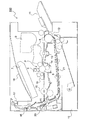
以下、図面を参照しながら本発明の実施形態について説明する。図1は、本発明のシート排出装置30が搭載された画像形成装置100の内部構造を示す側面断面図である。画像形成装置(例えばモノクロプリンター)100内には、帯電、露光、現像及び転写の各工程によりモノクロ画像を形成する画像形成部Pが配設されている。画像形成部Pには、感光体ドラム5の回転方向(図1の時計回り方向)に沿って、帯電ユニット4、露光ユニット(レーザー走査ユニット等)7、現像ユニット8、転写ローラー14、クリーニング装置19、及び除電装置(図示せず)が配設されている。
Hereinafter, embodiments of the present invention will be described with reference to the drawings. FIG. 1 is a side sectional view showing an internal structure of an
画像形成動作を行う場合、帯電ユニット4により時計回り方向に回転する感光体ドラム5が一様に帯電され、原稿画像データに基づく露光ユニット7からのレーザービームにより感光体ドラム5上に静電潜像が形成され、現像ユニット8により静電潜像に現像剤(以下、トナーという)が付着されてトナー像が形成される。
When the image forming operation is performed, the photosensitive drum 5 rotating in the clockwise direction is uniformly charged by the charging unit 4, and the electrostatic latent image is formed on the photosensitive drum 5 by the laser beam from the
この現像ユニット8へのトナーの供給はトナーコンテナ9から行われる。なお、画像データはパーソナルコンピューター(図示せず)等から送信される。また、感光体ドラム5の表面の残留電荷を除去する除電装置(図示せず)がクリーニング装置19の下流側に設けられている。
The toner is supplied to the developing
上記のようにトナー像が形成された感光体ドラム5に向けて、用紙が給紙カセット10又は手差し給紙装置11から用紙搬送路12及びレジストローラー対13を経由して搬送され、転写ローラー14(画像転写部)により感光体ドラム5の表面に形成されたトナー像が用紙に転写される。トナー像が転写された用紙は感光体ドラム5から分離され、定着装置15に搬送されてトナー像が定着される。定着装置15を通過した用紙は、用紙搬送路16により装置上部に搬送され、用紙の片面のみに画像を形成する場合(片面印字時)は、シート排出装置30(図2参照)の排出ローラー対17により排出トレイ18に排出される。
A sheet is conveyed from the
一方、用紙の両面に画像を形成する場合(両面印字時)は、用紙の後端が用紙搬送路16の湾曲部20を通過した後に搬送方向を逆転させる。これにより、用紙は湾曲部20から分岐する反転搬送路21に振り分けられ、画像面を反転させた状態でレジストローラー対13に再搬送される。そして、感光体ドラム5上に形成された次のトナー像が、転写ローラー14によって用紙の画像が形成されていない面に転写される。トナー像が転写された用紙は、定着装置15に搬送されてトナー像が定着された後、排出ローラー対17により排出トレイ18に排出される。
On the other hand, when images are formed on both sides of a sheet (during double-sided printing), the conveyance direction is reversed after the trailing edge of the sheet has passed through the
図2は、シート排出装置30を用紙排出方向下流側から見た斜視図である。排出ローラー対17は、用紙排出口31の幅方向(図2の左右方向)において略均等に4対配置されており、用紙搬送方向の上流側から搬送された用紙を排出トレイ18(図1参照)に排出する。
FIG. 2 is a perspective view of the
また、用紙排出方向に対し用紙排出口31の下流側近傍には、用紙排出口31から排出される用紙の上面を押圧する用紙押さえ部材50が配置されている。用紙押さえ部材50は、用紙幅方向の左右2箇所と中央1箇所の計3箇所において、揺動軸51(図3、図5参照)を支軸として用紙排出方向に揺動可能に支持されている。左右2箇所の用紙押さえ部材50は、中央の用紙押さえ部材50に比べて用紙幅方向に長く形成されている。
A
また、シート排出装置30の一端(図2の右端)には、排出トレイ18上に排出された用紙の満載状態を検知する満載検知部60が設けられている。図3に示すように、満載検知部60は、揺動軸51の一端に固定された遮光板61と、遮光板61によってON及びOFFの切り換えを行う検知センサー63とを有する。遮光板61は、用紙押さえ部材50の揺動に応じて上下に往復移動する。検知センサー63は、平面視コ字型の対向する内面に発光部及び受光部が設けられたPI(フォトインタラプター)センサーである。
In addition, a full-
排出トレイ18上に用紙が排出されていない状態では、用紙押さえ部材50は垂下しており、遮光板61は検知センサー63の発光部と受光部との間の光路を遮断している。排出トレイ18上に用紙が排出されていくと、用紙押さえ部材50の下端が用紙の上面に接触して徐々に上方に揺動し、揺動軸51に固定された遮光板61も上方に移動する。そして、排出トレイ18上に用紙が所定量排出されると、遮光板61が発光部と受光部との間の光路を開放することにより、受光部の受光信号レベルがLOWからHIGHに切り換わり、排出トレイ18上に排出された用紙が満載状態であることを検知可能となっている。
In a state where the sheet is not discharged onto the
なお、排出ローラー対17から用紙が排出される際に用紙押さえ部材50が揺動するため、遮光板61が上方に移動して発光部と受光部との間の光路が一時的に開放される。しかし、検知センサー63は受光信号レベルがLOWから一定時間継続してHIGHに切り換わることで用紙の満載状態を検知するため、用紙の排出動作によって用紙が満載状態であると誤検知されるおそれはない。
Since the
排出トレイ18上の用紙が満載であると検知された場合は、例えば操作パネルの液晶表示部(図示せず)にメッセージを表示してユーザーに通知する。即ち、用紙押さえ部材50は、排出トレイ18上の用紙の満載を検知する満載検知部材としての機能も兼ね備えている。
When it is detected that the sheets on the
図4は、排出ローラー対17付近を用紙排出方向下流側から見た斜視図であり、図5は、排出ローラー対17付近の側面図である。なお、図4及び図5は、図2における左端の排出ローラー対17について図示しているが、左から2番目の排出ローラー対17についても同様の構成である。また、右端及び右から2番目の排出ローラー対17については、蹴り出しプーリー45の配置が異なる以外は同様の構成である。
FIG. 4 is a perspective view of the vicinity of the
図4に示すように、排出ローラー対17は、樹脂製の第1ローラー21とゴム製の第2ローラー22とを備える。図5に示すように、第1ローラー21は第2ローラー22に対して下側、且つ用紙搬送方向の下流側(図5の右側)に配設されている。第1ローラー21が回転駆動すると、第2ローラー22が第1ローラー21と逆方向に従動回転する。第1ローラー21及び第2ローラー22のニップ部Nにて挟持された用紙S(図5の破線で表示)は、第1ローラー21及び第2ローラー22の回転(図5に矢印で表示)によって排出トレイ18に排出される。なお、第2ローラー22が回転駆動し、第2ローラー22の回転によって第1ローラー21が従動回転する構成であってもよい。
As shown in FIG. 4, the
第1ローラー21は、樹脂で形成された円筒状のローラー体42と、ローラー体42の中心からローラー幅方向(図4の左右方向)に延びる回転軸44と、を備える。回転軸44にはローラー体42と所定の間隔を隔てて円板状の蹴り出しプーリー45が形成されており、蹴り出しプーリー45の外周縁には複数(ここでは4個)の凸部41が形成されている。
The
凸部41は、第1ローラー21の回転に伴って排出される用紙の後端部を排出方向に押し出す(蹴り出す)ためのものであり、蹴り出しプーリー45の外周縁から径方向外側に突出する側面視略台形状に一体形成されている。
The
図5に示すように、4箇所の凸部41は蹴り出しプーリー45の周方向に均等に配置され、図5の上下方向に互いに対向する二つの第1凸部41aと、図5の左右方向に互いに対向する二つの第2凸部41bとからなる。
As shown in FIG. 5, the four
図6は、第1凸部41a、第2凸部41bを有する蹴り出しプーリー45の側面図である。なお、プーリー45は、4箇所の排出ローラー対17において共通の構成のものを使用するため、図5に示した左端の排出ローラー対17、或いは左から2番目の排出ローラー対17においては、第2凸部41bは用紙の後端を蹴り出す機能を有しない。一方、右端の排出ローラー対17、或いは右から2番目の排出ローラー対17の場合、第1ローラー21に対してプーリー45を逆向きに取り付けるため、プーリー45の回転方向が左側2箇所の排出ローラー対17と比べて相対的に逆方向になり、第2凸部41bが用紙の後端を蹴り出す機能を有し、第1凸部41aは機能しない構成になっている。
FIG. 6 is a side view of the kick-out
第1凸部41aは径方向先端部43a、傾斜面43b、及び押し出し部である第1押し出し面43cを有する。径方向先端部43aは、第1凸部41aのローラー径方向の最上辺を形成し、蹴り出しプーリー45の回転中心から径方向先端部43aまでの半径(距離)は、第1ローラー21のローラー体42の半径と同等以下の大きさに形成される。
The 1st
この構成により、用紙Sがニップ部Nにより挟持された状態で送り出されるとき、径方向先端部43aは用紙Sに当接するが、径方向先端部43aから用紙Sに押圧力(負荷)が加えられるおそれがない。従って、用紙Sの画像面を傷めずに用紙Sを排出ローラー対17から排出トレイ18に押し出すことができる。
With this configuration, when the paper S is sent out while being sandwiched by the nip portion N, the
傾斜面43bは、第1ローラー21の回転方向(図5の時計回り方向)に対し径方向先端部43aの上流側端部と蹴り出しプーリー45の外周縁とを連結するように緩やかに傾斜している。
The
第1押し出し面43cは、用紙Sの後端部に当接して用紙Sを排出トレイ18側に押し出すものであり、径方向先端部43aと蹴り出しプーリー45の外周縁とを連結する略垂直面である。また、第1押し出し面43cは、第1ローラー21の回転方向(図5の時計回り方向)に対して第1凸部41aの下流側端部に形成される。また、4箇所の排出ローラー対17の全てにおいて、プーリー45は用紙幅方向に対し第1ローラー21の外側に配置される。例えば、第1ローラー21が図2の左端、または左から2番目の排出ローラー対17に用いられる場合、図4に示すように、プーリー45は用紙排出方向の下流側から見て第1ローラー21の左側に配置され、第1押し出し面43cは、第1ローラー21の回転によって用紙Sの後端部に当接して用紙Sを排出トレイ18側に押し出す(蹴り出す)ことが可能となる。
The
一方、第2凸部41bは、径方向先端部43a、傾斜面43b、及び押し出し部である第2押し出し面43dを有する。第2凸部41bは、傾斜面43b、第2押し出し面43dの向きが異なる以外は第1凸部41aと同様の構成である。
On the other hand, the 2nd
具体的には、傾斜面43bは、第1ローラー21の回転方向(図5の時計回り方向)に対し径方向先端部43aの下流側端部と蹴り出しプーリー45の外周縁とを連結するように緩やかに傾斜して設けられる。
Specifically, the
第2押し出し面43dは、用紙Sの後端部に当接し用紙Sを排出トレイ18側に押し出すものであり、径方向先端部41cと蹴り出しプーリー45の外周縁とを連結する略垂直面である。また、第2押し出し面43dは、第1ローラー21の回転方向(図5の時計回り方向)に対して第2凸部41aの上流側に形成される。第1ローラー21が図2の右端、または右から2番目の排出ローラー対17に用いられる場合、第2押し出し面43dは、第1ローラー21の回転によって用紙Sの後端部に当接して用紙Sを排出トレイ18側に押し出す(蹴り出す)ことが可能となる。
The second push-out
さらに、図2の右端及び右から2番目に配設された第1ローラー21の第2押し出し面43dは、図2の左端及び左から2番目に配設された第1ローラー21の第1押し出し面43cと同じ周方向位置(同位相)に配置されるように組み立てられる。その結果、第1ローラー21が図5の時計回り方向に回転したとき、左端及び左から2番目の第1ローラー21の第1押し当て面43cと、右端及び右から2番目の第1ローラー21の第2押し当て面43dとは同時に用紙Sの後端部に当接し、各第1凸部41a、第2凸部41bは用紙Sを排出トレイ18側に押し出す。
Further, the second push-out
ところで、排出ローラー対17を通過する用紙が逆カール(画像面と逆向きのカール)している場合、凸部41による押し出し力が用紙の後端に十分に伝達されず、用紙の後端が用紙排出口31付近に残存してしまうことがある。そこで、本実施形態では、凸部41による押し出し(蹴り出し)性を強化するために、排出ローラー対17に対向して配置される左右の用紙押さえ部材50に押圧リブ53を設けている。
By the way, when the paper passing through the
押圧リブ53は、用紙押さえ部材50の排出ローラー対17との対向面50aに、揺動軸51の軸方向において蹴り出しプーリー45(凸部41)と重なる位置に形成されている。押圧リブ53は、頂部53aから揺動軸51方向に傾斜する第1傾斜面53bと、頂部53aから用紙押さえ部材50の先端部50b方向に傾斜する第2傾斜面53cとを有する側面視山型状に形成される。押圧リブ53は、用紙押さえ部材50の幅方向のほぼ中央に配置されている。なお、押圧リブ53は、4箇所の排出ローラー対17のうち、外側2箇所(左端及び右端)の排出ローラー対17に対向しており、内側2箇所(左から2番目、及び右から2番目)の排出ローラー対17に対向する位置には設けられていない。
The
次に、押圧リブ53によって用紙の押し出し(蹴り出し)が強化される仕組みについて説明する。図5に示すように、排出ローラー対17のニップ部Nを通過した用紙Sの先端が用紙押さえ部材50の対向面50aに到達すると、用紙Sは用紙押さえ部材50を反時計回り方向に揺動させながら排出方向に搬送される。用紙Sの排出方向は、対向面50aに連続する押圧リブ53の第1傾斜面53bに沿って徐々に下向きとなる。
Next, a mechanism for strengthening the pushing (kicking out) of the paper by the
ここで、第1傾斜面53aは、用紙押さえ部材50の対向面50aに滑らかに連続するように形成されているため、用紙Sの先端が対向面50aから押圧リブ53に乗り上げる際に衝突音が発生せず、用紙Sの排出方向を円滑に変更することができる。
Here, since the first
そして、押圧リブ53が揺動軸51の軸方向において凸部41と重なる位置に形成されているため、用紙Sが用紙押さえ部材50を揺動させながら押圧リブ53の頂部53aを通過するとき、排出方向下流側(図5の右側)から見て頂部53aが凸部41の高さ以下に位置することとなる。これにより、用紙Sの後端が頂部53aによって下方へ押圧され、押圧リブ53と凸部41とで用紙Sが上下から挟み込まれるようにして排出されるため、逆カールした用紙Sであっても凸部41に対向する部分を確実に下方向に押圧することができ、凸部41による用紙Sの後端の押し出しを強化し、後端残りを防止することができる。
Since the
なお、用紙Sが押圧リブ53の頂部53aを通過するとき、頂部53aが凸部41よりも下側にあると、用紙Sを上下から挟み込む力が強くなり凸部41の用紙Sに対する押圧力が高くなり過ぎるおそれがある。そのため、用紙Sが押圧リブ53の頂部53aを通過している間は頂部53aと凸部41とが同一高さ(水平位置)にあることが好ましい。
When the paper S passes through the top 53a of the
このようにして、排出ローラー対17から排出された用紙Sは、押圧リブ53が設けられた用紙押さえ部材50によって下方向に押圧され、蹴り出しプーリー45に形成された凸部41によって排出方向に確実に押し出されて排出トレイ18上に排出される。従って、用紙排出口31付近に用紙Sが残存するおそれがなく、排出トレイ18上の用紙の整列性を向上させることができる。
In this way, the sheet S discharged from the
図7は、排出トレイ18上の用紙が満載状態であるときの排出ローラー対17付近の側面図である。排出トレイ18上に排出された用紙の上面が一定以上の高さになると、用紙押さえ部材50の回動によって検知センサー63(図3参照)の光路が遮断され、排出トレイ18上の用紙が満載状態であることが検知される。ここで、用紙押さえ部材50の先端部50bは、押圧リブ53よりも下流側にある。一方、図1に示したように、排出トレイ18は用紙排出方向上流側(図1の左側)に向けて下方へ傾斜している。そのため、排出トレイ18上に排出された用紙の上面も、排出トレイ18に沿って用紙排出方向上流側に向けて下方へ傾斜する。
FIG. 7 is a side view of the vicinity of the
従って、図7に示すように、用紙押さえ部材50の揺動によって用紙の満載状態が検知されるとき、押圧リブ53の第2傾斜面53cの水平面に対する角度が用紙の上面(図7の一点鎖線L)の角度よりも緩やかであれば、用紙押さえ部材50の先端部50bのみが用紙の上面に当接し、押圧リブ53の頂部53aや第2傾斜面53cは用紙の上面に当接しない。このような位置関係とすることにより、押圧リブ53が満載状態の検知に影響を及ぼすおそれはない。
Therefore, as shown in FIG. 7, when the full state of the sheet is detected by the swing of the
その他本発明は、上記実施形態に限定されず、本発明の趣旨を逸脱しない範囲で種々の変更が可能である。例えば、上記実施形態では、左端及び右端の排出ローラー対17に対向する用紙押さえ部材50に押圧リブ53を設けたが、例えば左から2番目、或いは右から2番目の排出ローラー対17に対向する用紙押さえ部材50をさらに設け、この用紙押さえ部材50にも押圧リブ53を形成しても良い。
In addition, this invention is not limited to the said embodiment, A various change is possible in the range which does not deviate from the meaning of this invention. For example, in the above-described embodiment, the
また、上記実施形態では、用紙押さえ部材50の揺動軸51に検知センサー63の光路を開閉する遮光板61を固定し、用紙押さえ部材50が満載検知部材としての機能も兼ね備えた構成について説明したが、用紙押さえ部材50とは別個に満載検知部材が設けられている構成であっても良い。或いは、満載検知部材を有しない構成であっても良い。
Further, in the above-described embodiment, the configuration in which the
また、本発明は図1に示したようなモノクロプリンターに限らず、カラープリンター、モノクロ及びカラー複写機、デジタル複合機、或いはファクシミリ等、他のタイプの画像形成装置にも適用できるのはもちろんである。 Further, the present invention is not limited to the monochrome printer as shown in FIG. 1, but can be applied to other types of image forming apparatuses such as color printers, monochrome and color copiers, digital multifunction peripherals, and facsimiles. is there.
本発明は、画像形成装置に搭載されるシート排出装置に利用可能である。本発明の利用により、シートを傷つけることなく、またシート上の画像を傷めることなく、排出ローラー対からシートを確実に押し出すシート排出装置、及びそれを備えた画像形成装置を提供することができる。 The present invention can be used for a sheet discharge device mounted on an image forming apparatus. By using the present invention, it is possible to provide a sheet discharge device that reliably pushes out a sheet from a pair of discharge rollers without damaging the sheet and without damaging an image on the sheet, and an image forming apparatus including the sheet discharge device.
17 排出ローラー対
18 排出トレイ
21 第1ローラー
22 第2ローラー
30 シート排出装置
31 用紙排出口
41 凸部
41a 第1凸部
41b 第2凸部
42 ローラー体
44 回転軸
45 蹴り出しプーリー
50 用紙押さえ部材(シート押さえ部材)
50a 対向面
50b 先端部
51 揺動軸
53 押圧リブ
53a 頂部
53b 第1傾斜面
53c 第2傾斜面
60 満載検知部
61 遮光板
63 検知センサー
100 画像形成装置
17
Claims (7)
該排出口から排出されたシートを受ける排出トレイと、
第1ローラーと該第1ローラーに上方から圧接される第2ローラーとを有し、前記第1ローラーと前記第2ローラーのニップ部にシートを挟持して前記排出口から前記排出トレイにシートを排出する排出ローラー対と、
前記第1ローラーの回転軸と同軸上に、前記第1ローラーの端部から間隔を隔てて形成され、外周縁から突出する複数の凸部を有する蹴り出しプーリーと、
シート排出方向に対し前記排出ローラー対の下流側近傍に設けられ、シート排出方向と直交するシート幅方向に延びる揺動軸に支持され、前記シート排出方向に揺動可能であって前記シート幅方向に所定の範囲で延在し、前記排出ローラー対に対向するシート押さえ部材と、
を備えたシート排出装置において、
前記シート押さえ部材は、前記排出ローラー対との対向面の前記シート幅方向の中央部から突出する押圧リブを有し、前記押圧リブは、前記シート排出方向から見て前記蹴り出しプーリーと前記シート幅方向において重なる位置に形成されることを特徴とするシート排出装置。 A discharge port for discharging the sheet;
A discharge tray for receiving sheets discharged from the discharge port;
A first roller and a second roller pressed against the first roller from above; the sheet is sandwiched between nip portions of the first roller and the second roller, and the sheet is discharged from the discharge port to the discharge tray. A pair of discharge rollers to discharge,
A kick-out pulley that is formed coaxially with the rotation axis of the first roller and spaced from the end of the first roller, and has a plurality of protrusions protruding from the outer periphery,
To the sheet discharging direction provided in the vicinity of the downstream side of the discharge roller pair is supported by a swing shaft extending in the sheet width direction orthogonal to the sheet discharging direction, the sheet width direction to a swingable said sheet discharging direction A sheet pressing member extending in a predetermined range and facing the discharge roller pair ;
In a sheet discharge device comprising:
Said sheet pressing member has a pressing rib projecting from a central portion of the seat width direction of the opposing surfaces of the discharge roller pair, the pressing ribs, the said sheet out the kick when viewed from the discharge direction pulley sheet A sheet discharging device, wherein the sheet discharging device is formed at an overlapping position in the width direction.
前記シート押さえ部材がシートの満載状態を検知する位置まで揺動したとき、前記第2傾斜面の水平面に対する角度は前記排出トレイ上に積載されるシートの上面の角度よりも緩やかであることを特徴とする請求項2乃至請求項5のいずれかに記載のシート排出装置。 The sheet pressing member also serves as a full load detection member that detects the full load state of the sheets stacked on the discharge tray by swinging in the sheet discharge direction.
When the sheet pressing member swings to a position for detecting a full sheet state, the angle of the second inclined surface with respect to the horizontal plane is gentler than the angle of the upper surface of the sheets stacked on the discharge tray. The sheet discharging apparatus according to any one of claims 2 to 5.
Priority Applications (3)
| Application Number | Priority Date | Filing Date | Title |
|---|---|---|---|
| JP2014177957A JP6021865B2 (en) | 2014-09-02 | 2014-09-02 | Sheet discharging apparatus and image forming apparatus having the same |
| US14/835,668 US9611119B2 (en) | 2014-09-02 | 2015-08-25 | Sheet discharging device and image forming apparatus therewith |
| CN201510530569.3A CN105383985B (en) | 2014-09-02 | 2015-08-26 | Sheet discharge device and the image processing system for possessing the sheet discharge device |
Applications Claiming Priority (1)
| Application Number | Priority Date | Filing Date | Title |
|---|---|---|---|
| JP2014177957A JP6021865B2 (en) | 2014-09-02 | 2014-09-02 | Sheet discharging apparatus and image forming apparatus having the same |
Publications (2)
| Publication Number | Publication Date |
|---|---|
| JP2016050103A JP2016050103A (en) | 2016-04-11 |
| JP6021865B2 true JP6021865B2 (en) | 2016-11-09 |
Family
ID=55401671
Family Applications (1)
| Application Number | Title | Priority Date | Filing Date |
|---|---|---|---|
| JP2014177957A Active JP6021865B2 (en) | 2014-09-02 | 2014-09-02 | Sheet discharging apparatus and image forming apparatus having the same |
Country Status (3)
| Country | Link |
|---|---|
| US (1) | US9611119B2 (en) |
| JP (1) | JP6021865B2 (en) |
| CN (1) | CN105383985B (en) |
Families Citing this family (2)
| Publication number | Priority date | Publication date | Assignee | Title |
|---|---|---|---|---|
| US11827043B2 (en) | 2018-05-11 | 2023-11-28 | Hewlett-Packard Development Company, L.P. | Knockdown for compiling recording media in finisher |
| JP7077844B2 (en) * | 2018-07-25 | 2022-05-31 | 京セラドキュメントソリューションズ株式会社 | Image forming device |
Family Cites Families (16)
| Publication number | Priority date | Publication date | Assignee | Title |
|---|---|---|---|---|
| JPH05294530A (en) * | 1992-04-20 | 1993-11-09 | Fuji Xerox Co Ltd | Copy discharging device of image forming device |
| JP2931557B2 (en) * | 1996-01-24 | 1999-08-09 | エヌティエヌ株式会社 | Roller for conveying a sheet of an image forming apparatus |
| US5915690A (en) * | 1997-05-22 | 1999-06-29 | Troy Systems, Inc. | Adjustable low paper sensor |
| JP2006168955A (en) * | 2004-12-17 | 2006-06-29 | Oki Data Corp | Medium delivery mechanism and image forming apparatus |
| JP5339931B2 (en) * | 2008-01-30 | 2013-11-13 | キヤノン株式会社 | Sheet discharging apparatus and image forming apparatus |
| JP4497214B2 (en) * | 2008-02-29 | 2010-07-07 | ブラザー工業株式会社 | Document feeder |
| JP5169642B2 (en) * | 2008-05-28 | 2013-03-27 | 株式会社リコー | Paper discharge device and image forming apparatus |
| JP5393246B2 (en) * | 2008-05-29 | 2014-01-22 | キヤノン株式会社 | Sheet stacking apparatus and image forming apparatus |
| JP4569675B2 (en) * | 2008-06-25 | 2010-10-27 | ブラザー工業株式会社 | Document feeder |
| JP5390164B2 (en) * | 2008-10-17 | 2014-01-15 | 富士通フロンテック株式会社 | Paper sheet discharge and accumulation device |
| JP4770952B2 (en) * | 2009-03-13 | 2011-09-14 | 富士ゼロックス株式会社 | Discharge mechanism and image forming apparatus |
| JP4531107B1 (en) * | 2009-05-27 | 2010-08-25 | シャープ株式会社 | Paper discharge device and image forming apparatus |
| JP5779969B2 (en) * | 2011-05-13 | 2015-09-16 | ブラザー工業株式会社 | Sheet transport device |
| JP5538446B2 (en) * | 2012-01-19 | 2014-07-02 | 京セラドキュメントソリューションズ株式会社 | Sheet discharging apparatus, image forming apparatus including the same, and post-processing apparatus |
| JP6164401B2 (en) * | 2013-02-28 | 2017-07-19 | 株式会社リコー | Paper discharge device and image forming apparatus having the same |
| JP6233245B2 (en) * | 2014-08-28 | 2017-11-22 | 京セラドキュメントソリューションズ株式会社 | Sheet discharging apparatus and image forming apparatus having the same |
-
2014
- 2014-09-02 JP JP2014177957A patent/JP6021865B2/en active Active
-
2015
- 2015-08-25 US US14/835,668 patent/US9611119B2/en active Active
- 2015-08-26 CN CN201510530569.3A patent/CN105383985B/en active Active
Also Published As
| Publication number | Publication date |
|---|---|
| CN105383985B (en) | 2017-12-05 |
| JP2016050103A (en) | 2016-04-11 |
| US20160060065A1 (en) | 2016-03-03 |
| US9611119B2 (en) | 2017-04-04 |
| CN105383985A (en) | 2016-03-09 |
Similar Documents
| Publication | Publication Date | Title |
|---|---|---|
| JP5590739B2 (en) | Recording medium discharging apparatus and image forming apparatus having the same | |
| JP6493246B2 (en) | Stacked sheet detection device, image forming device | |
| JP2010266799A (en) | Sheet ejecting unit and image forming apparatus | |
| JP6818404B2 (en) | Sheet ejection device and image forming device | |
| JP7163082B2 (en) | Sheet discharge device and image forming device | |
| US20180237240A1 (en) | Image forming apparatus and image forming method | |
| JP6021865B2 (en) | Sheet discharging apparatus and image forming apparatus having the same | |
| US8023837B2 (en) | Image forming apparatus capable of preventing a sheet jamming during detected abnormal situations | |
| JP5153285B2 (en) | Image forming apparatus | |
| JP6233245B2 (en) | Sheet discharging apparatus and image forming apparatus having the same | |
| JP2017081686A (en) | Sheet discharge device and image formation device | |
| JP2011068445A (en) | Paper ejecting device and image forming device mounted with the same | |
| JP2007062928A (en) | Image formation device | |
| JP4097564B2 (en) | Sheet ejector | |
| JP6204307B2 (en) | Image forming apparatus | |
| JP5802806B2 (en) | Recording medium discharging apparatus and image forming apparatus having the same | |
| JP2001226016A (en) | Image forming device | |
| JP2004142845A (en) | Detection device | |
| JP7415546B2 (en) | image forming device | |
| JP2009073591A (en) | Sheet member discharging device, and image forming device | |
| JP6673655B2 (en) | Sheet conveying apparatus and image forming apparatus having the same | |
| JP2017206331A (en) | Sheet discharge device and image formation apparatus having the same | |
| JP6512772B2 (en) | Sheet discharge apparatus and image forming apparatus | |
| JP2022133859A (en) | Sheet detection device, paper discharge device, and image forming device | |
| JP5660287B2 (en) | Recording medium conveying apparatus and image forming apparatus |
Legal Events
| Date | Code | Title | Description |
|---|---|---|---|
| A621 | Written request for application examination |
Free format text: JAPANESE INTERMEDIATE CODE: A621 Effective date: 20160520 |
|
| A871 | Explanation of circumstances concerning accelerated examination |
Free format text: JAPANESE INTERMEDIATE CODE: A871 Effective date: 20160520 |
|
| A975 | Report on accelerated examination |
Free format text: JAPANESE INTERMEDIATE CODE: A971005 Effective date: 20160603 |
|
| A131 | Notification of reasons for refusal |
Free format text: JAPANESE INTERMEDIATE CODE: A131 Effective date: 20160614 |
|
| A521 | Request for written amendment filed |
Free format text: JAPANESE INTERMEDIATE CODE: A523 Effective date: 20160802 |
|
| TRDD | Decision of grant or rejection written | ||
| A01 | Written decision to grant a patent or to grant a registration (utility model) |
Free format text: JAPANESE INTERMEDIATE CODE: A01 Effective date: 20160906 |
|
| A61 | First payment of annual fees (during grant procedure) |
Free format text: JAPANESE INTERMEDIATE CODE: A61 Effective date: 20161004 |
|
| R150 | Certificate of patent or registration of utility model |
Ref document number: 6021865 Country of ref document: JP Free format text: JAPANESE INTERMEDIATE CODE: R150 |