JP6020552B2 - Image display device and optical device - Google Patents
Image display device and optical device Download PDFInfo
- Publication number
- JP6020552B2 JP6020552B2 JP2014503328A JP2014503328A JP6020552B2 JP 6020552 B2 JP6020552 B2 JP 6020552B2 JP 2014503328 A JP2014503328 A JP 2014503328A JP 2014503328 A JP2014503328 A JP 2014503328A JP 6020552 B2 JP6020552 B2 JP 6020552B2
- Authority
- JP
- Japan
- Prior art keywords
- display
- lens
- light
- plano
- oblique
- Prior art date
- Legal status (The legal status is an assumption and is not a legal conclusion. Google has not performed a legal analysis and makes no representation as to the accuracy of the status listed.)
- Expired - Fee Related
Links
Images


Classifications
-
- G—PHYSICS
- G02—OPTICS
- G02B—OPTICAL ELEMENTS, SYSTEMS OR APPARATUS
- G02B30/00—Optical systems or apparatus for producing three-dimensional [3D] effects, e.g. stereoscopic images
- G02B30/20—Optical systems or apparatus for producing three-dimensional [3D] effects, e.g. stereoscopic images by providing first and second parallax images to an observer's left and right eyes
- G02B30/26—Optical systems or apparatus for producing three-dimensional [3D] effects, e.g. stereoscopic images by providing first and second parallax images to an observer's left and right eyes of the autostereoscopic type
- G02B30/27—Optical systems or apparatus for producing three-dimensional [3D] effects, e.g. stereoscopic images by providing first and second parallax images to an observer's left and right eyes of the autostereoscopic type involving lenticular arrays
-
- H—ELECTRICITY
- H04—ELECTRIC COMMUNICATION TECHNIQUE
- H04N—PICTORIAL COMMUNICATION, e.g. TELEVISION
- H04N13/00—Stereoscopic video systems; Multi-view video systems; Details thereof
- H04N13/30—Image reproducers
- H04N13/302—Image reproducers for viewing without the aid of special glasses, i.e. using autostereoscopic displays
- H04N13/305—Image reproducers for viewing without the aid of special glasses, i.e. using autostereoscopic displays using lenticular lenses, e.g. arrangements of cylindrical lenses
-
- H—ELECTRICITY
- H04—ELECTRIC COMMUNICATION TECHNIQUE
- H04N—PICTORIAL COMMUNICATION, e.g. TELEVISION
- H04N13/00—Stereoscopic video systems; Multi-view video systems; Details thereof
- H04N13/30—Image reproducers
- H04N13/302—Image reproducers for viewing without the aid of special glasses, i.e. using autostereoscopic displays
- H04N13/317—Image reproducers for viewing without the aid of special glasses, i.e. using autostereoscopic displays using slanted parallax optics
Landscapes
- Physics & Mathematics (AREA)
- Engineering & Computer Science (AREA)
- Multimedia (AREA)
- Signal Processing (AREA)
- Optics & Photonics (AREA)
- General Physics & Mathematics (AREA)
- Testing, Inspecting, Measuring Of Stereoscopic Televisions And Televisions (AREA)
Description
本発明は、画像表示装置及び光学装置に関する。 The present invention relates to an image display device and an optical device.
隣接した2つのカメラで撮影された画像の視差を利用して立体視が可能な画像を生成する立体画像生成装置がある。立体視画像生成装置は、例えば、隣接した2つのカメラで撮影した画像のうち、一方のカメラによる画像を左眼用画像として、他方のカメラによる画像を右眼用画像として、生成して表示する。
同一の対象物に対して、左眼用画像における位置と、右眼用画像における位置との差を、視差という。画像内に存在する2つの対象物で、視差量が異なることにより、一方の対象物が他方の対象物に対して手前又は奥に存在するように見える。視差量は、視差の大きさである。There is a stereoscopic image generation device that generates an image that can be stereoscopically viewed using the parallax of images captured by two adjacent cameras. The stereoscopic image generation device generates and displays, for example, an image taken by one of two adjacent cameras as an image for the left eye and an image obtained by the other camera as an image for the right eye. .
The difference between the position in the left-eye image and the position in the right-eye image with respect to the same object is called parallax. Since two objects existing in the image have different parallax amounts, it appears that one object exists in front of or behind the other object. The amount of parallax is the magnitude of parallax.
また、立体画像生成装置には、液晶ディスプレイ等の表示装置にレンチキュラー状のレンズ(レンチキュラーレンズ)を設置することにより、専用の眼鏡を使用することなく、左眼及び右眼にそれぞれ異なった映像を認識させるものもある。具体的には、表示装置と視聴者との間に、レンチキュラーレンズを連続して並べて構成したレンズシートを配置する。 In addition, by installing a lenticular lens (lenticular lens) on a display device such as a liquid crystal display, a stereoscopic image generating device can display different images for the left eye and the right eye without using dedicated glasses. There are also things to recognize. Specifically, a lens sheet configured by continuously arranging lenticular lenses is disposed between the display device and the viewer.
すなわち、表示装置上に左眼用の映像と右眼用の映像を交互に表示し、レンチキュラーレンズを通して見ることによって、左眼には左眼用の画像だけが、又、右眼には右眼の画像だけが見えるようになり、立体映像として認識できる。
また、解像度の劣化を表示画像の縦方向と横方向とに分散させることで、高い画質を得る斜めレンチキュラーレンズ方式も知られている。That is, the left-eye image and the right-eye image are alternately displayed on the display device and viewed through the lenticular lens so that only the left-eye image is displayed on the left eye and the right-eye image is displayed on the right eye. Only the image of the image becomes visible, and can be recognized as a stereoscopic image.
An oblique lenticular lens system is also known that obtains high image quality by dispersing resolution deterioration in the vertical and horizontal directions of a display image.
図11は従来の立体画像生成装置における表示装置の画素配列とレンチキュラーレンズとの関係を例示する図である。なお、この図11中においては、便宜上、レンズシートを構成する複数のレンチキュラーレンズ511のうち、一のレンチキュラーレンズ511のみを示している。又、この図11中においては、レンチキュラーレンズ511を破線で示している。
FIG. 11 is a diagram illustrating a relationship between a pixel arrangement of a display device and a lenticular lens in a conventional stereoscopic image generation device. In FIG. 11, for convenience, only one
この図11に示す例においては、レンチキュラーレンズ511を表示装置の表示面510aの表示素子の配列の方向に対して斜めに配置している。表示面510a上では、色画素の表示素子は、表示面510aに対して横方向(配列方向)及び、横方向に対して直交する縦方向に配列される。図11の例では、表示面510aの表示素子の配列の縦方向に対して、斜め方向(非平行の方向)にレンチキュラーレンズ511を配置する。
In the example shown in FIG. 11, the
これにともなって、表示面510aで表示する各画素は、斜め方向に並んだ表示素子を用いて表示する。この図11に示す例においては、便宜上、一の画素を形成する表示素子に対して、同一のアルファベットを識別符号として付している。
例えば、この図11に示す例においては、表示素子であるB12、G22、R32が、1つの画素(画素D)を形成する。又、他の表示素子についても同様である。各画素における表示素子の並び方向と各レンチキュラーレンズ511の方向とは平行である。図11の例では、斜め方向に1つの画素が配置される。Accordingly, each pixel displayed on the
For example, in the example shown in FIG. 11, the display elements B12, G22, and R32 form one pixel (pixel D). The same applies to other display elements. The arrangement direction of the display elements in each pixel and the direction of each
ここで、画素Dを表示する3つの表示素子から出た光は、そのほとんどが同一のレンチキュラーレンズ511に入射され、当該レンズにより利用者の、予め規定された左右いずれかの眼の位置で結像される。他の画素についても同様である。又、左眼用画像の画素と右眼用画像の画素とは、交互に配置される。
図11のように、レンチキュラーレンズ511を表示素子の配列に対して斜めに配置し、1つの画素を斜め方向に配置することにより、縦方向と横方向とで均等に解像度の劣化が生じる。すなわち、縦方向もしくは横方向のいずれか一方においてのみ解像度が下がることを防ぐことができる。縦方向と横方向との両方向で解像度の低下が生じる方が、縦方向もしくは横方向の一方のみで解像度の低下が生じた場合に比べて、視聴者において画質の劣化が少なく見える。
As shown in FIG. 11, when the
しかしながら、例えば、図11に例示した従来の立体映像生成装置において、レンチキュラーレンズ511には、例えば、色画素G12,B22,R22,G32等の、画素D以外の画素を形成する色画素から出力される光も進入し、クロストークが生じる。
本発明は、このような課題に鑑み創案されたもので、斜めレンチキュラーレンズ方式におけるクロストークの発生を阻止することを目的とする。However, for example, in the conventional stereoscopic video generation device illustrated in FIG. 11, the
The present invention has been devised in view of such a problem, and an object thereof is to prevent the occurrence of crosstalk in an oblique lenticular lens system.
なお、前記目的に限らず、後述する発明を実施するための最良の形態に示す各構成により導かれる作用効果であって、従来の技術によっては得られない作用効果を奏することも本発明の他の目的の1つとして位置付けることができる。 In addition, the present invention is not limited to the above-described object, and is an operational effect derived from each configuration shown in the best mode for carrying out the invention described later, and has an operational effect that cannot be obtained by conventional techniques. It can be positioned as one of the purposes.
上記の目的を達成するために、この画像表示装置は、表示素子を配列方向及び当該配列方向と直行する方向に並べることにより、前記表示素子をマトリクス状に配置した表示部と、前記表示部において、前記配列方向に対して傾斜した方向に連続する複数の表示素子による斜列表示素子群に対応させて、当該斜列表示素子群に沿って配置され、前記斜列表示素子群を成す各表示素子からの出力光を結像させるレンズを複数並べて配置したレンズユニットと、前記レンズに対応する前記斜列表示素子群を成す表示素子以外の表示素子である不要成分出力素子からの出力光が、当該レンズから出射することを阻止する遮光部とをそなえ、前記遮光部が、前記複数の表示素子の内、前記配列方向に対して傾斜した方向に連続する複数の表示素子による斜列表示素子群に対応させて形成され、前記不要成分出力素子における当該レンズと対向する領域である遮光対象領域と同一形状を有する。 In order to achieve the above object, the image display apparatus includes a display unit in which the display elements are arranged in a matrix by arranging the display elements in an arrangement direction and a direction orthogonal to the arrangement direction. The display elements that are arranged along the oblique display element group in correspondence with the oblique display element group of a plurality of display elements that are continuous in a direction inclined with respect to the arrangement direction, and that constitute the oblique display element group. Output light from an unnecessary component output element that is a display element other than a display unit that constitutes the oblique display element group corresponding to the lens, and a lens unit in which a plurality of lenses that image output light from the element are arranged side by side. includes a light shielding portion for preventing the emitted from the lens, the light shielding part, among the plurality of display elements, a plurality of display elements continuously in a direction inclined with respect to the arrangement direction Formed to correspond to the oblique column display element group, it includes the a region facing the corresponding lens in unnecessary component output element shielding the target area and the same shape.
また、この光学装置は、表示素子を配列方向及び当該配列方向と直行する方向に並べることにより、前記表示素子をマトリクス状に配置した表示部に取り付けられる光学装置であって、前記表示部において、前記配列方向に対して傾斜した方向に連続する複数の表示素子による斜列表示素子群に対応させて、当該斜列表示素子群に沿って配置され、前記斜列表示素子群を成す各表示素子からの出力光を結像させるレンズを複数並べて配置したレンズユニットと、前記レンズに対応する前記斜列表示素子群を成す表示素子以外の表示素子である不要成分出力素子からの出力光が、当該レンズから出射することを阻止する遮光部とをそなえ、前記遮光部が、前記複数の表示素子の内、前記配列方向に対して傾斜した方向に連続する複数の表示素子による斜列表示素子群に対応させて形成され、前記不要成分出力素子における当該レンズと対向する領域である遮光対象領域と同一形状を有する。 Further, the optical device is an optical device that is attached to a display unit in which the display elements are arranged in a matrix by arranging the display elements in an arrangement direction and a direction orthogonal to the arrangement direction. Each display element that is arranged along the oblique display element group in correspondence with the oblique display element group of a plurality of display elements that are continuous in a direction inclined with respect to the arrangement direction, and forms the oblique display element group Output light from an unnecessary component output element that is a display element other than a display unit that constitutes the oblique display element group corresponding to the lens, and a lens unit in which a plurality of lenses that form an image of the output light from the lens unit are arranged. includes a light shielding portion for preventing the emitted from the lens, the light shielding part, among the plurality of display elements, a plurality of display elements continuously in a direction inclined with respect to the arrangement direction According formed in correspondence with the oblique column display element group, includes the a region facing the corresponding lens in unnecessary component output element shielding the target area and the same shape.
開示の技術によれば、クロストークの発生を阻止することができる。 According to the disclosed technique, occurrence of crosstalk can be prevented.
以下、図面を参照して本立体画像表示装置及び光学装置に係る実施の形態を説明する。ただし、以下に示す実施形態はあくまでも例示に過ぎず、実施形態で明示しない種々の変形例や技術の適用を排除する意図はない。すなわち、本実施形態を、その趣旨を逸脱しない範囲で種々変形(実施形態及び各変形例を組み合わせる等)して実施することができる。又、各図は、図中に示す構成要素のみを備えるという趣旨ではなく、他の機能等を含むことができる。 Hereinafter, embodiments of the stereoscopic image display device and the optical device will be described with reference to the drawings. However, the embodiment described below is merely an example, and there is no intention to exclude application of various modifications and techniques not explicitly described in the embodiment. In other words, the present embodiment can be implemented with various modifications (combining the embodiments and modifications) without departing from the spirit of the present embodiment. Each figure is not intended to include only the components shown in the figure, and may include other functions.
(A)第1実施形態
図1は第1実施形態の一例としての立体画像表示装置1の構成を模式的に示す図、図2はその表示装置10の表示素子の配列の例を示す図である。
本立体画像表示装置(画像表示装置)1においては、表示面10aにレンズシート11を取り付けた表示装置10に対向するように視聴者が位置し、その表示面10aに表示対象物の立体表示用画像(立体画像)を表示させることにより、視聴者に表示対象物が立体的に視認される。(A) First Embodiment FIG. 1 is a diagram schematically illustrating a configuration of a stereoscopic
In the stereoscopic image display device (image display device) 1, a viewer is positioned so as to face the
立体表示用画像は、例えば、隣接した2つのカメラで撮影した画像であり、これらの2つのカメラのうち、一方のカメラによる画像を左眼用画像として、他方のカメラによる画像を右眼用画像として用いる。これらの視差を有する2つの画像により立体視が可能となる。なお、立体表示用画像は、既知の種々の手法を用いて作成することができ、その詳細な説明は省略する。又、本立体画像表示装置1で表示される立体表示用画像(3D映像)は、動画であっても静止画像であってもよい。
The stereoscopic display image is, for example, an image captured by two adjacent cameras. Of these two cameras, the image from one camera is used as the left eye image, and the image from the other camera is used as the right eye image. Used as Stereoscopic viewing is possible with these two images having parallax. Note that the stereoscopic display image can be created using various known methods, and detailed description thereof is omitted. The stereoscopic display image (3D video) displayed on the stereoscopic
第1実施形態の一例としての立体画像表示装置1は、図1に示すように、表示装置10,レンズシート(光学装置)11及び表示制御部12をそなえる。
表示装置10は、例えば、液晶ディスプレイであり、表示制御部12からの制御に従って、その表示面10aに画像を表示する。すなわち、本立体画像表示装置1においては、この表示装置10に立体表示用画像が表示される。又、立体表示用画像には左眼用画像及び右眼用画像を含む。以下、表示装置10が液晶ディスプレイの例について示し、表示装置10を液晶ディスプレイ10と示す場合がある。As shown in FIG. 1, a stereoscopic
The
液晶ディスプレイ10の表示面10aは平面として形成され、この表示面10aには複数の色画素の素子(表示素子)が、表示面10aの横方向(図1や図2の横方向;配列方向)及び、横方向に対して直交する縦方向(図1や図2の縦方向)に配列される。すなわち、液晶ディスプレイ10の表示面10aは、表示素子を配列方向及びこの配列方向と直行する方向に並べることにより、表示素子をマトリクス状に配置している。
The
そして、表示面10aに表示される画像(立体画像)を構成する複数の画素は、それぞれ表示素子(表示エレメント)によって表現される。
具体的には、各画素は複数の色画素を含む。色画素の例は、例えば、赤(R;Red),緑(G;Green)及び青(B;Blue)の光の三原色をなす色画素である。表示面10aにおいては、図2に例示するように、これらの色画素の表示素子が配列方向に所定の順序で繰り返し配置されている。又、配列方向に直行する方向には、同種類の表示素子が連続して配置されている。各表示素子の境界部分には、ブラックマトリクスを配置してもよい。そして、表示面10aにおいて、連続するR,G,Bの3つの色画素の表示素子によって一つの画素が表される。A plurality of pixels constituting an image (stereoscopic image) displayed on the
Specifically, each pixel includes a plurality of color pixels. An example of the color pixel is a color pixel that forms the three primary colors of light of red (R; Red), green (G; Green), and blue (B; Blue). On the
また、本第1実施形態において、各色画素の表示素子は発光部分が矩形形状をそなえる矩形表示エレメントである。
本立体画像表示装置1においては、図2に例示するような表示面10aの表示素子の配列の縦方向に対して、斜め方向(非平行の方向)に並ぶ(連続する)R,G,Bの3つの色画素の表示素子によって一つの画素を表す。すなわち、斜め方向に1つの画素が配置される。図1や図2に示す例においては、便宜上、同一の画素を形成する色画素の表示素子に対して、同一のアルファベットを識別符号として付している。In the first embodiment, the display element of each color pixel is a rectangular display element in which the light emitting portion has a rectangular shape.
In the stereoscopic
例えば、図2に示す例においては、色画素の表示素子であるB12、G22、R32が、1つの画素(画素D)を形成する。又、他の色画素の表示素子についても同様である。
図2中において、横方向(配列方向)をx方向、縦方向をy方向とした場合に、例えば、表示素子G22の位置を座標(m,n)と表した場合に、表示素子B12の位置は座標(m+1,n+1)で表される。同様に表示素子R32の位置は座標(m−1,n−1)で表される。
For example, in the example shown in FIG. 2, B12, G22, and R32, which are display elements for color pixels, form one pixel (pixel D). The same applies to display elements of other color pixels.
In FIG. 2, when the horizontal direction (arrangement direction) is the x direction and the vertical direction is the y direction, for example, when the position of the display element G22 is expressed as coordinates ( m , n ), the position of the display element B12 Is represented by coordinates (m + 1, n + 1). Similarly, the position of the display element R32 is represented by coordinates (m-1, n-1).
本立体画像表示装置1は、これらの、座標(m−1,n−1),(m,n)及び(m+1,n+1)の斜め方向に位置する3つの表示素子により、一の画素を形成する。以下、液晶ディスプレイ10において、一の画素を形成する、斜め方向に位置する3つの表示素子を斜列表示素子群という。
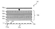
図3は第1実施形態の一例としての立体画像表示装置1の液晶ディスプレイ10の構成を模式的に例示する図である。The stereoscopic
FIG. 3 is a diagram schematically illustrating the configuration of the
液晶ディスプレイ10は、例えば、図3に示すように、バックライト10g及び液晶パネル10bをそなえる。なお、図3においては、液晶ディスプレイ10の一例として、一般的な透過型液晶パネルをそなえる液晶ディスプレイ10を示す。
バックライト10gは、光源であり、液晶パネル10bに光を照射する。
液晶パネル10bは、バックライト10gから照射された光を、部分的に遮ったり透過させたりすることによって表示素子による表示を行なう。液晶パネル10bは、拡散板10c,偏光板10d,10e及び液晶セル10fをそなえる。For example, as shown in FIG. 3, the
The
The
拡散板10cは、バックライト10gから照射された光を拡散させ、偏光板10d,10eや液晶セル10fに均一に光が当るようにする。
偏光板10d,10eは、バックライト10gから照射された光のうち、特定の方向に振幅成分を持つ光(偏光)だけを通過させる偏光フィルタである。これらの偏光板10d,10eは、互いに異なる(例えば、互いに直交する)方向の振幅成分の光を通過させる。
The
偏光板10dと偏光板10eとの間には液晶セル10fが配置されている。液晶セル10fは、電極や配向膜,スペーサ,カラーフィルタ等をそなえ、配向膜やスペーサ等で構成される枠内に液晶材料を封入したセルが形成されている。これにより、R,G,Bの各色画素の表示素子が形成される。
液晶パネル10bには、後述するレンズシート11が、その平面110b側を偏光板10eに対向させて配置される。又、レンズシート11における平面110bには、後述する遮光部101が部分的に形成されている。
The
In the
バックライト10gから照射された光は、拡散板10c,偏光板10d,液晶セル10f及び偏光板10eの順に通過し、レンズシート11に進入する。この際、レンズシート11において遮光部101が配置された部分では、この遮光部101が液晶パネル10bから照射される光の進入を阻止する。すなわち、レンズシート11において、遮光部101が不在の部分にバックライト10gから照射された光が進入し、この進入した光が平凸面レンズ110を通過する。
The light irradiated from the
そして、この平凸面レンズ110を通過した光は、凸レンズ110aから出射され、視聴者の眼で結像される。
本第1実施形態においては、液晶ディスプレイ10が、例えば、23インチのモニタサイズであり、1600×900(ドット)程度の解像度をそなえる。このような一般的な液晶ディスプレイ10においては、R,G,Bの各表示素子のサイズは、水平方向(図2中の横方向)に0.418mm、垂直方向(図2の縦方向)に0.705mm程度である。
And the light which passed this plano-
In the first embodiment, the
なお、液晶ディスプレイ10の解像度やサイズ、表示素子のサイズは、これらに限定されるものではなく、適宜変更して実施することができる。又、図3においては、透過型液晶パネルをそなえる液晶ディスプレイ10を示しているが、液晶ディスプレイ10としては、他の種々の方式の液晶ディスプレイ10を用いることができる。
図4は第1実施形態の一例としての立体画像表示装置1の表示制御部12のハードウェア構成を模式的に示す図である。It should be noted that the resolution and size of the
FIG. 4 is a diagram schematically illustrating a hardware configuration of the display control unit 12 of the stereoscopic
表示制御部12は、図4に示すように、例えば、CPU(Central Processing Unit)131,LAN(Local Area Network)カード132,チューナ133,グラフィック・アクセラレータ134,チップセット135,メモリ136,オーディオコントローラ137,HDD(Hard Disk Drive)138,ブルーレイディスク(Blu-ray Disc)ドライブ139及びキーボードコントローラ140をそなえる情報処理装置(コンピュータ)として構成される。
As shown in FIG. 4, the display control unit 12 includes, for example, a CPU (Central Processing Unit) 131, a LAN (Local Area Network)
グラフィック・アクセラレータ134は、液晶ディスプレイ10が接続され、この液晶ディスプレイ10に対して画像表示を行なわせるための画像表示制御インタフェースである。なお、このグラフィック・アクセラレータ134としての機能をチップセット135に持たせてもよい。LANカード132はインターネット等のネットワークに接続するためのインタフェースカードであり、チューナ133は外部アンテナ142が接続され、TV番組を受信し、デコード等の処理を行ない映像データとして表示装置10に表示させる。
The
メモリ136は、例えばRAM(Random Access Memory)やROM(Read Only Memory)等の記憶装置であり、CPU131が実行もしくは使用する各種プログラムやデータを格納する。
オーディオコントローラ137は、スピーカ143が接続され、このスピーカ143に対する音声データの出力を制御する。The
The
HDD138は記憶装置であり、CPU131が実行もしくは使用するOS(Operating System)や各種プログラム、データ等を格納する。又、このHDD138やメモリ136には、表示装置10に表示される各種画像データ(映像データ,立体画像データ)も格納される。
そして、このHDD138には、立体表示対象(表示対象)について予め作成された立体画像データが格納されている。すなわち、HDD138は、表示対象についての視差点毎の立体表示用画像を複数視点毎に格納する格納部として機能する。The
The
ブルーレイディスクドライブ139は、ブルーレイディスクを再生する。なお、このブルーレイディスクに、液晶ディスプレイ10に表示される各種画像データ(映像データ,立体画像データ)を格納してもよい。又、ブルーレイディスク以外の記録媒体(例えば、DVD等)を再生可能な再生装置をそなえ、この記録媒体に格納された各種画像データを再生してもよい。
The Blu-
キーボードコントローラ140はキーボード144やマウス145等の入力装置が接続され、これらのキーボード144やマウス145とCPU131と間のデータのやり取りを制御する。チップセット135には、これらの各部がバス等を介して接続され、CPU131とこれら各部との通信を制御する。
CPU131は、HDD138やメモリ136に格納されたプログラムを実行することにより各種機能を実現する処理装置である。The
The
CPU131は、例えば、画像再生アプリケーションを実行することにより、動画像や静止画像等のコンテンツを液晶ディスプレイ10の表示面10aに表示させ、表示制御部12としての画像表示機能を実現する。
例えば、表示制御部12は、液晶ディスプレイ10の表示面を構成する複数の斜列表示素子群(表示素子)のうち、右眼用画像の表示に用いる特定の斜列表示素子群に右眼用画像を表示させる。同様に、表示制御部12は、液晶ディスプレイ10の表示面を構成する複数の斜列表示素子群(表示素子)のうち、左眼用画像の表示に用いる特定の斜列表示素子群に左眼用画像を表示させる。表示制御部12は、これらの制御を行なうことにより、液晶ディスプレイ10に立体画像を表示させる。For example, by executing an image reproduction application, the
For example, the display control unit 12 uses the right eye for a specific oblique display element group used for displaying the right eye image among a plurality of oblique display element groups (display elements) constituting the display surface of the
そして、表示制御部12は、表示する立体画像の一の画素に対応させて、液晶ディスプレイ10の表示面10aにおける、斜列表示素子群を成す3つの表示素子の輝度値等をそれぞれ制御することにより、液晶ディスプレイ10に立体画像を表示させる。具体的には、表示制御部12は、例えば、バックライト10gや液晶パネル10bを制御して、バックライト10gの光源によって画素光を発生させる。
Then, the display control unit 12 controls the luminance values and the like of the three display elements forming the oblique display element group on the
また、表示制御部12は、表示する画像の一の画素に対応させて、液晶ディスプレイ10の表示面10aにおいて、配列方向に並ぶR,G,Bの3つの表示素子の輝度値等をそれぞれ制御することにより、液晶ディスプレイ10に画像を表示させてもよい。
液晶ディスプレイ10に表示する画像は、例えば、HDD138やメモリ136,ブルーレイディスク等に記録されていてもよく、又、LANカード132やチューナ133を介して受信してもよく、種々変形して実施することができる。
Further, the display control unit 12 controls the brightness values of the three display elements R, G, and B arranged in the arrangement direction on the
The image displayed on the
なお、このような画像表示機能等の各種機能を実現するためのプログラム(画像再生アプリケーション)は、例えばフレキシブルディスク,CD(CD−ROM,CD−R,CD−RW等),DVD(DVD−ROM,DVD−RAM,DVD−R,DVD+R,DVD−RW,DVD+RW等),ブルーレイディスク,磁気ディスク,光ディスク,光磁気ディスク等の、コンピュータ読取可能な記録媒体に記録された形態で提供される。そして、コンピュータはその記録媒体からプログラムを読み取って内部記憶装置または外部記憶装置に転送し格納して用いる。又、そのプログラムを、例えば磁気ディスク,光ディスク,光磁気ディスク等の記憶装置(記録媒体)に記録しておき、その記憶装置から通信経路を介してコンピュータに提供するようにしてもよい。 Note that programs (image reproduction application) for realizing various functions such as the image display function include, for example, a flexible disk, CD (CD-ROM, CD-R, CD-RW, etc.), DVD (DVD-ROM). , DVD-RAM, DVD-R, DVD + R, DVD-RW, DVD + RW, etc.), Blu-ray disc, magnetic disc, optical disc, magneto-optical disc, and the like. Then, the computer reads the program from the recording medium, transfers it to the internal storage device or the external storage device, and uses it. The program may be recorded in a storage device (recording medium) such as a magnetic disk, an optical disk, or a magneto-optical disk, and provided from the storage device to the computer via a communication path.
画像表示機能等の各種機能を実現する際には、内部記憶装置(本実施形態ではメモリ136)に格納されたプログラムがコンピュータのマイクロプロセッサ(本実施形態ではCPU131)によって実行される。このとき、記録媒体に記録されたプログラムをコンピュータが読み取って実行するようにしてもよい。
なお、本実施形態において、コンピュータとは、ハードウェアとオペレーティングシステムとを含む概念であり、オペレーティングシステムの制御の下で動作するハードウェアを意味している。又、オペレーティングシステムが不要でアプリケーションプログラム単独でハードウェアを動作させるような場合には、そのハードウェア自体がコンピュータに相当する。ハードウェアは、少なくとも、CPU等のマイクロプロセッサと、記録媒体に記録されたコンピュータプログラムを読み取るための手段とをそなえており、本実施形態においては、立体画像表示装置1がコンピュータとしての機能を有しているのである。When realizing various functions such as an image display function, a program stored in an internal storage device (
In the present embodiment, the computer is a concept including hardware and an operating system, and means hardware that operates under the control of the operating system. Further, when an operating system is unnecessary and hardware is operated by an application program alone, the hardware itself corresponds to a computer. The hardware includes at least a microprocessor such as a CPU and means for reading a computer program recorded on a recording medium. In this embodiment, the stereoscopic
表示制御部12としての機能は既知の種々の手法により実現することができ、その詳細な説明は省略する。
レンズシート(レンズユニット)11は、レンチキュラーレンズであり、カマボコ状の複数の平凸面レンズ(レンズ)110を、各平凸面レンズ110の母線を平行に連続して並べたレンズアレイとして構成されている。The function as the display control unit 12 can be realized by various known methods, and detailed description thereof is omitted.
The lens sheet (lens unit) 11 is a lenticular lens, and is configured as a lens array in which a plurality of planar convex-convex lenses (lenses) 110 are continuously arranged in parallel with the generatrix of each plano-
レンズシート11は、図3に示すように、液晶ディスプレイ10の表示面10a側において、各平凸面レンズ110において突出する凸レンズ110aとは反対側の平面110bを表示装置10の表示面10aに対向させて配置される。
図5は表示装置10に対するレンズシート11の取り付けの例を示す図である。レンズシート11は、この図5に示すように、表示装置10の表示面10aの前方(視聴者側)の所定位置に固定して取り付けられる。液晶ディスプレイ10へのレンズシート11の取り付けは、例えば、図示しないフック等に固定することにより行なう。このようにレンズシート11を液晶ディスプレイ10の表示面10aから脱着自在に構成することにより、レンズシート11を液晶ディスプレイ10から取り外した状態で、当該液晶ディスプレイ10を一般的な2次元画像表示装置としても用いることができる。なお、レンズシート11を液晶ディスプレイ10の表示面10aに貼着してもよい。As shown in FIG. 3, the
FIG. 5 is a diagram illustrating an example of attachment of the
そして、レンズシート11において、各平凸面レンズ110の凸レンズ110aの光軸は、互いに平行に配置されており、これにより、各平凸面レンズ110が同一方向を向いて形成されている。
各平凸面レンズ110は、同一の材質で形成されるとともに、凸レンズ110aの曲率や凸レンズ110aの頂部から平面110bまでの距離等、互いに同じ形状をそなえ、それぞれのf値が等しい。In the
Each plano-
また、このレンズシート11は、図1に示すように、各平凸面レンズ110が、前述した液晶ディスプレイ10における、一の画素を形成する斜列表示素子群と平行に、これらの斜列表示素子群に重なるように配置される。すなわち、レンズシート11は、各平凸面レンズ110の母線が表示面10aにおける表示素子の並列方向に対して斜めになるように配置される。
In addition, as shown in FIG. 1, the
具体的には、レンズシート11を構成する平凸面レンズ110は、液晶ディスプレイ10における、座標(m−1,n−1),(m,n),(m+1,n+1)の、斜め方向に位置する3つの表示素子(斜列表示素子群)の並びに沿って、これらの3つの表示素子と重なるように配設される。すなわち、平凸面レンズ110は、液晶ディスプレイ10の表示面10aにおける表示素子の並列方向に対して斜めに配置される。
Specifically, the plano-
これにより、表示面10a側において斜列表示素子群を構成する3つの表示素子から照射される光が、それぞれ同一の各平凸面レンズ110の平面110b(裏面)に入射される。
すなわち、一の斜列表示素子群を構成する3つの表示素子から出力される光は、同じ平凸面レンズ110に入射される。又、液晶ディスプレイ10の表示面10aにおける各斜列表示素子群は、それぞれ一の平凸面レンズ110に対応する。以下、斜列表示素子群と、当該斜列表示素子群に対応する平凸面レンズ110との組み合わせを出力対という。平凸面レンズ110には、この出力対を構成する斜列表示素子群から出力される光が入射される。
As a result, light emitted from the three display elements constituting the oblique display element group on the
That is, light output from three display elements constituting one oblique display element group is incident on the same plano-
一の画素を成す斜列表示素子群(例えば、R32,G22,B12)からそれぞれ出力された光(3原色)は、平凸面レンズ110を透過した後、それぞれ凸レンズ110aから出射される。そして、これらの光は、液晶ディスプレイ10の表示面10aから所定定距離だけ離れた位置において交差し結像する。具体的には、平凸面レンズ110を透過した光は、視聴者の左右いずれかの眼だけに結像される。
Lights (three primary colors) respectively output from the oblique display element group (for example, R32, G22, B12) constituting one pixel are transmitted through the plano-
このように、平凸面レンズ110は、液晶ディスプレイ10の表示面10aにおいて、斜列表示素子群に対応させて、この斜列表示素子群に沿って配置され、斜列表示素子群を成す各表示素子からの出力光を結像させる。
なお、出力光の結像位置は、例えば、平凸面レンズ110の焦点距離や、液晶ディスプレイ10の表示面10aと平凸面レンズ110との距離等に応じて規定される。従って、視聴者の位置や姿勢等に基づいて、これらの焦点距離等を、出力光が視聴者の眼の位置に結像するよう、予め最適な値に設定しておく。これらの焦点距離の設定手法等は既知の種々の手法により実現され、その詳細な説明は省略する。
Thus, the plano-
Note that the imaging position of the output light is defined according to, for example, the focal length of the plano-
本立体画像表示装置1においては、前述の如く、1画素に1つの平凸面レンズ110を対応させるので、1画素の光線は光の強さ(光量)を落とすことなく、且つ、正確な焦点距離を持って結像することができる。
また、レンズシート11において、各平凸面レンズ110は、当該平凸面レンズ110と出力対を成す斜列表示素子群を構成する表示素子とは異なる他の表示素子からの出力光(不要画素成分)が、当該平凸面レンズ110から出力されることを阻止する遮光部101をそなえる。In the stereoscopic
Further, in the
この遮光部101は、当該平凸面レンズ110と出力対を成す斜列表示素子群を構成する表示素子とは異なる他の表示素子からの出力光(不要画素成分)が、当該平凸面レンズ110に入射されることを阻止することにより、この不要画素成分が当該平凸面レンズ110から出力されることを阻止する。
以下、不要画素成分を出力する、当該平凸面レンズ110と出力対を成す斜列表示素子群を構成する表示素子とは異なる他の表示素子を不要成分出力素子という場合がある。The
Hereinafter, another display element that outputs an unnecessary pixel component and is different from the display element that constitutes the oblique display element group that forms an output pair with the plano-
遮光部101は、平面110b側において不要成分出力素子から出力される不要画素成分を遮光することにより、この不要画素成分が平凸面レンズ110に入射されることを阻止する。
不要成分出力素子は、当該平凸面レンズ110の出力対を成す斜列表示素子群と、縦もしくは横方向において隣接する表示素子であり、当該平凸面レンズ110の平面110bと対向(重合)する表示素子である。以下、不要成分出力素子における、当該平凸面レンズ110と重合する領域を遮光対象領域という。The
The unnecessary component output element is a display element adjacent in the vertical or horizontal direction to the oblique display element group forming the output pair of the plano-
図6は第1実施形態の一例としての立体画像表示装置1における液晶ディスプレイ10と平凸面レンズ110と遮光部101との位置関係を模式的に示す断面図である。この図6に示すように、遮光部101は、平凸面レンズ110の平面110bと液晶ディスプレイ10の表示面10aとの間に配置されている。なお、この図6に示す例においては、便宜上、平凸面レンズ110と遮光部101とが間隙を隔てて配置されているが、平凸面レンズ110と遮光部101とは密着させることが望ましい。
FIG. 6 is a cross-sectional view schematically showing a positional relationship among the
遮光部101は、不要成分出力素子から出力される光(不要画素成分)が平凸面レンズ110の平面110bに入射されることを阻止する。
遮光部101は、例えば、黒色ポリエチレン等の遮光性の高い材質をフィルム状に構成した遮光フィルム(黒色ポリエチレン製遮光フィルム)であり、平凸面レンズ110の平面110bに貼着される。The
The light-shielding
ただし、遮光部101の構成はこれに限定されるものではなく、種々変形して実施することができる。例えば、遮光部101として、黒色ポリエチレン以外の素材を用いてもよく、又、遮光部101は、遮光フィルムを平凸面レンズ110に貼着する代わりに、遮光性の高い材質を平凸面レンズ110の平面110bに塗布することにより実現してもよい。更に、遮光部101を、平凸面レンズ110の平面110b側に配置する代わりに、凸レンズ110a側に配置して、平凸面レンズ110からの不要画素成分の出力を阻止してもよい。
However, the structure of the light-shielding
図7及び図8は、それぞれ、第1実施形態の一例としての立体画像表示装置1におけるレンズシート11の遮光部101の形状を説明するための図である。図7は平凸面レンズ110と不要成分出力素子との位置関係を示す図、図8は図7に示す遮光対象領域を示す図である。なお、便宜上、図7中においては一つの遮光部101だけを示しており、又、図8中においては遮光部101の図示を省略している。
7 and 8 are diagrams for explaining the shape of the
遮光部101は、平凸面レンズ110において、レンズシート11が液晶ディスプレイ10に取り付けられた状態で、当該平凸面レンズ110の平面110bが不要成分出力素子に対向(重合)する領域(遮光対象領域)を覆う位置に形成される。
以下に、図7及び図8を参照しながら、遮光対象領域について説明する。
図7に示すように、矩形形状を有する表示素子の横方向の長さをAとし、その縦方向の長さをBとする。又、平凸面レンズ110の幅をCとする。各表示素子は液晶ディスプレイ10の表示面10aの全面においてそれぞれ同一の寸法形状を有する。In the plano-
Hereinafter, the light shielding target region will be described with reference to FIGS. 7 and 8.
As shown in FIG. 7, the horizontal length of a display element having a rectangular shape is A, and the vertical length is B. The width of the plano-
図7に示す例において、平凸面レンズ110は、その母線(図7中の一点鎖線参照)が一の斜列表示素子群を構成する表示素子R32,G22,B12の対角線に一致するように配置されている。
そして、この図7に示す例において、一の画素を成す斜列表示素子群(R32,G22,B12)と出力対をなす(対応する)平凸面レンズ110については、表示素子G12,B22からそれぞれ出力される光が不要画素成分である。In the example shown in FIG. 7, the plano-
In the example shown in FIG. 7, the plano-
これらの表示素子G12,B22における不要画素成分を出力する領域、すなわち、表示素子G12,B22における、斜列表示素子群(R32,G22,B12)と対応する平凸面レンズ110と対向する領域は、遮光対象領域である。図7中において、表示素子G12における遮光対象領域を符号T1で、又、表示素子B22における遮光対象領域を符号T2で、それぞれ示す。
An area for outputting an unnecessary pixel component in these display elements G12 and B22, that is, an area facing the plano-
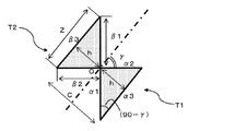
三角形T2の三辺をβ1,β2,β3とする。この三角形T2において、直角である頂点Oは辺β3に対向する。同様に、三角形T1の三辺をα1,α2,α3とする。この三角形T1において、直角である頂点Oは辺α3に対向する。
これらの遮光対象領域T1,T2は、互いに相似(合同)な直角三角形状である。従って、「辺β1の長さ=辺α1の長さ」,「辺β2の長さ=辺α2の長さ」及び「辺β3の長さ=辺α3の長さ」である。Let the three sides of the triangle T2 be β1, β2, and β3. In the triangle T2, a vertex O that is a right angle faces the side β3. Similarly, the three sides of the triangle T1 are α1, α2, and α3. In this triangle T1, a vertex O that is a right angle faces the side α3.
These light shielding target regions T1 and T2 are similar (congruent) right triangle shapes. Therefore, “the length of the side β1 = the length of the side α1”, “the length of the side β2 = the length of the side α2”, and “the length of the side β3 = the length of the side α3”.
ここで、図7に示すように、表示素子(例えば、B12)の一の対角線が当該表示素子の横方向に沿う辺と成す角度をγとする。平凸面レンズ110の母線をこの対角線に合わせることにより、母線と表示素子の横方向に沿う辺とが成す角度がγになる。
図8に示すように、遮光対象領域である三角形T1,T2において、縦方向に沿う辺と対角線とが成す角度は(90−γ)である。このため
tan(90−γ)=A/B、及び、tanγ=B/A
が成立する。Here, as shown in FIG. 7, an angle formed by one diagonal line of the display element (for example, B12) with a side along the horizontal direction of the display element is γ. By aligning the generatrix of the plano-
As shown in FIG. 8, in the triangles T <b> 1 and T <b> 2 that are light shielding target regions, the angle formed between the side along the vertical direction and the diagonal line is (90−γ). For this reason
tan (90−γ) = A / B and tan γ = B / A
Is established.
また、三角形T1における、辺α3から頂点Oまでの高さhと、三角形T2における、辺β3から頂点Oまでの高さhとの合計はCである。よって、
辺β3の長さ(Z)=[C/2]/tan(90−γ)+[C/2]/tan(γ)
= C×[A×A+B×B]/AB・・・(式1)
となる。The sum of the height h from the side α3 to the vertex O in the triangle T1 and the height h from the side β3 to the vertex O in the triangle T2 is C. Therefore,
Length of side β3 (Z) = [C / 2] / tan (90−γ) + [C / 2] / tan (γ)
= C × [A × A + B × B] / AB (Formula 1)
It becomes.
本第1実施形態においては、各遮光部101は、平凸面レンズ110における母線に沿って、少なくとも上記式(1)によって求められる[辺β3の長さ(Z)]と同じ寸法をそなえ、又、母線と直交する方向(レンズ幅方向)には、平凸面レンズ110の幅Cの全体に亘って形成される。すなわち、遮光部101は、平凸面レンズ110における母線方向に上記[辺β3の長さ(Z)]と同じ寸法をそなえ、且つ、レンズ幅方向にレンズ幅Cと同じ寸法をそなえる矩形領域として形成される。
In the first embodiment, each
また、各平凸面レンズ110においては、複数の遮光部101が母線に沿って等間隔に繰り返し形成され、隣接する遮光部101どうしの間隔も上記式(1)によって求められる[辺β3の長さ(Z)]とする。これにより、平凸面レンズ110において、複数の遮光部101が、不要成分出力素子の遮光対象領域に対応して形成される。
このように、遮光部101が形成されたレンズシート11が本願の光学装置として機能する。Further, in each plano-
Thus, the
上述の如く構成された第1実施形態の一例としての立体画像表示装置1において、立体画像の表示を行なう場合には、先ず、上述の如く構成された、レンズシート11と遮光部101とをそなえる光学装置を、例えば、図5に示すように、液晶ディスプレイ10に取り付ける。このレンズシート11は、上述の如く、不要成分出力素子の遮光対象領域に対応させて複数の遮光部101をそなえる平凸面レンズ110を複数有する。
In the stereoscopic
レンズシート11における各平凸面レンズ110の母線は、図7に示すように、液晶ディスプレイ10の表示面10aにおける各斜列表示素子群の並びと平行となるように、矩形の表示素子の一の対角線に沿って斜めに配置される。すなわち、平凸面レンズ110は、斜列表示素子群の対角線と重なるように配置される。又、各平凸面レンズ110の幅寸法Cは、液晶ディスプレイ10の表示面10aの各表示素子の横方向長さAに対応して形成されている。例えば、平凸面レンズ110の幅Cは、例えば、C=Asinγを満たすように構成される。
As shown in FIG. 7, the bus line of each plano-
これにより、液晶ディスプレイ10の表示面10aにおける各斜列表示素子群は、いずれかの平凸面レンズ110に対応する。そして、斜列表示素子群を構成する各表示素子の並び方向(各表示素子を連通する対角線)と各平凸面レンズ110の母線の方向とは一致する。
この状態において、表示制御部12が、液晶ディスプレイ10に立体画像を表示させる。具体的には、表示する立体画像の一の画素に対応させて、液晶ディスプレイ10の表示面10aにおける、斜列表示素子群を成す3つの表示素子の輝度値等をそれぞれ制御することにより、液晶ディスプレイ10に立体画像を表示させる。Accordingly, each oblique display element group on the
In this state, the display control unit 12 displays a stereoscopic image on the
レンズシート11においては、斜列表示素子群から出力される光が、出力対を成す平凸面レンズ110の平面110bに入射し、その凸レンズ110aから照射されて、予め規定された位置にある視聴者の眼に結像する。
ただし、レンズシート11において、平凸面レンズ110には、当該平凸面レンズ110の出力対ではない不要成分出力素子から出力された光は、遮光部101により、その平面110bへの進入が阻止される。In the
However, in the
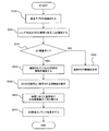
次に、本第1実施形態の一例としての立体画像表示装置1における表示制御部12の処理を、図9に示すフローチャート(ステップS10〜S80)に従って例示する。
本立体画像表示装置1において、画像再生アプリケーション(再生アプリ)が起動されると、(ステップS10)、画像再生アプリケーション(表示制御装置12)は、先ず、当該立体画像表示装置1がレンズ式の立体画像表示装置1であるか否かを確認する(ステップS20)。この確認は、例えば、本立体画像表示装置1の表示制御装置13のメモリ136やHDD138等に格納されている機種ID等を確認することにより行なう。Next, the process of the display control unit 12 in the stereoscopic
When the image reproduction application (reproduction application) is activated in the stereoscopic image display device 1 (step S10), the image reproduction application (display control device 12) first has the three-dimensional
その後、表示装置10にレンズシート11(3Dパネル)が取り付けられているか否かを確認する(ステップS30)。例えば、表示制御部12は、表示装置10におけるレンズシート11の取り付けを検知するセンサの検知結果に基づき、レンズシート11が取り付けられているか否かの判断を行なう。
この判断の結果、レンズシート11が表示装置10に取り付けられていない場合には(ステップS30のNOルート参照)、2D表示を行なう(ステップS80)。すなわち、左眼用画像と右眼用画像とで同じ画像を表示装置10に表示させる。又、この際、表示装置10に、立体画像表示を行なうことができない旨を示すダイアログボックスを表示させてもよい。Thereafter, it is confirmed whether or not the lens sheet 11 (3D panel) is attached to the display device 10 (step S30). For example, the display control unit 12 determines whether or not the
If the result of this determination is that the
また、レンズシート11が表示装置10に取り付けられていて3D表示を行なうことができる場合には(ステップS30のYESルート参照)、その取り付けられているレンズシート11のシートIDを確認して、3D方式の種類を確認する(ステップS40)。これは、表示する視差数(3D映像が確認される場所の数)によって表示画素群の設定が変わるからである。
When the
表示制御部12は、確認された3D方式種類により表示される視差数を設定し(ステップS50)、設定に応じた視差数での左右の映像表示へ切り替える(ステップS60)。
そして、表示制御部12は、右眼用の視差画像及び左眼用の視差画像(3D映像コンテンツ)を、表示素子を用いて表示させることにより、3D表示を行ない(ステップS70)。処理を終了する。
このように、第1実施形態の一例としての立体画像表示装置1によれば、レンズシート11において、平凸面レンズ110には、当該平凸面レンズ110の出力対ではない不要成分出力素子から出力された光は、遮光部101により、その平面110bへの進入が阻止される。これにより、クロストークの発生を阻止することができる。The display control unit 12 sets the number of parallaxes displayed according to the confirmed 3D system type (step S50), and switches to left and right video display with the number of parallaxes according to the setting (step S60).
Then, the display control unit 12 performs 3D display by displaying the parallax image for the right eye and the parallax image for the left eye (3D video content) using the display element (step S70). The process ends.
As described above, according to the stereoscopic
(B)第2実施形態
図10は第2実施形態の一例としての立体画像表示装置1の構成を模式的に示す図である。
第2実施形態の一例としての立体画像表示装置1は、第1実施形態の平凸面レンズ110に形成された矩形形状を有する遮光部101に代えて、図10に示すように、遮光対象領域と同様の形状を有する遮光部101aをそなえるものであり、その他の部分は第1実施形態の立体画像表示装置1と同様に構成されている。(B) Second Embodiment FIG. 10 is a diagram schematically illustrating a configuration of a stereoscopic
The stereoscopic
すなわち、本第2実施形態の立体画像表示装置1においては、平凸面レンズ110において、遮光部101aは、図7及び図8において三角形T1,T2で表された遮光対象領域と同様の形状を有する。
このように、第2実施形態の一例としての立体画像表示装置1によれば、上述した第1実施形態と同様の作用効果を得ることができる他、遮光部101aが、平凸面レンズ110と出力対を成す斜列表示素子群からの、当該平凸面レンズ110に入力される光の進入を阻止することがない。これにより、平凸面レンズ110と出力対を成す斜列表示素子群の各表示素子から出力される光の輝度低下等が生じることがない。
That is, the present in the stereoscopic
As described above, according to the stereoscopic
(C)その他
そして、本発明は上述した実施形態に限定されるものではなく、本発明の趣旨を逸脱しない範囲で種々変形して実施することができる。
例えば、上述した各実施形態においては、表示装置10が液晶ディスプレイである例を示しているが、これに限定されるものではなく、例えば、プラズマディスプレイ等、液晶ディスプレイ以外の表示装置であってもよく、適宜変形して実施することができる。(C) Others The present invention is not limited to the above-described embodiments, and various modifications can be made without departing from the spirit of the present invention.
For example, in each of the embodiments described above, an example in which the
また、上述した各実施形態においては、液晶ディスプレイ10がR,G,Bの3種類の色画素の表示素子をそなえる例を示しているが、これに限定されるものではなく、R,G,B以外の表示素子を用いてもよい。
上記各実施形態において、遮光部101,101aは、液晶ディスプレイ10の表示面10aの遮光対象領域に対応して設けられるが、遮光部101,101aは、これらの遮光対象領域を必ずしも完全に覆う必要はない。すなわち、遮光部101,101aが遮光対象領域の少なくとも一部を覆うように配置し、この遮光対象領域の一部から出力される光が平凸面レンズ110に入射されることを阻止してもよい。これにより、クロストークを小さくすることができるという効果を奏するとができる。Moreover, in each embodiment mentioned above, although the
In each of the above embodiments, the
なお、本発明の各実施形態が開示されていれば、本発明の画像表示装置及び光学装置を当業者によって実施・製造することが可能である。
(付記1)
表示素子を配列方向及び当該配列方向と直行する方向に並べることにより、前記表示素子をマトリクス状に配置した表示部と、
前記表示部において、前記配列方向に対して傾斜した方向に連続する複数の表示素子による斜列表示素子群に対応させて、当該斜列表示素子群に沿って配置され、前記斜列表示素子群を成す各表示素子からの出力光を結像させるレンズを複数並べて配置したレンズユニットと、
前記レンズに対応する前記斜列表示素子群を成す表示素子以外の表示素子である不要成分出力素子からの出力光が、当該レンズから出射することを阻止する遮光部とをそなえることを特徴とする、画像表示装置。
(付記2)
前記遮光部が、前記表示部と前記レンズとの間に配置され、前記不要成分出力素子からの出力光が前記レンズへ入射されることを阻止することを特徴とする、付記1記載の画像表示装置。
(付記3)
前記遮光部が、前記不要成分出力素子における当該レンズと対向する領域である遮光対象領域に対応して形成されることを特徴とする、付記1又は2記載の画像表示装置。
(付記4)
前記遮光部が、前記遮光対象領域を包含する領域として形成されることを特徴とする、付記3記載の画像表示装置。
(付記5)
前記遮光部が、前記遮光対象領域と同一形状を有することを特徴とする、付記3記載の画像表示装置。
(付記6)
表示素子を配列方向及び当該配列方向と直行する方向に並べることにより、前記表示素子をマトリクス状に配置した表示部に取り付けられる光学装置であって、
前記表示部において、前記配列方向に対して傾斜した方向に連続する複数の表示素子による斜列表示素子群に対応させて、当該斜列表示素子群に沿って配置され、前記斜列表示素子群を成す各表示素子からの出力光を結像させるレンズを複数並べて配置したレンズユニットと、
前記レンズに対応する前記斜列表示素子群を成す表示素子以外の表示素子である不要成分出力素子からの出力光が、当該レンズから出射することを阻止する遮光部とをそなえることを特徴とする、光学装置。
(付記7)
前記遮光部が、前記表示部と前記レンズとの間に配置され、前記不要成分出力素子からの出力光が前記レンズへ入射されることを阻止することを特徴とする、付記6記載の光学装置。
(付記8)
前記遮光部が、前記不要成分出力素子における当該レンズと対向する領域である遮光対象領域に対応して形成されることを特徴とする、付記6又は7記載の光学装置。
(付記9)
前記遮光部が、前記遮光対象領域を包含する領域として形成されることを特徴とする、付記8記載の光学装置。
(付記10)
前記遮光部が、前記遮光対象領域と同一形状を有することを特徴とする、付記8記載の光学装置。
If each embodiment of the present invention is disclosed, the image display device and optical device of the present invention can be implemented and manufactured by those skilled in the art.
(Appendix 1)
A display unit in which the display elements are arranged in a matrix by arranging the display elements in an arrangement direction and a direction perpendicular to the arrangement direction;
In the display unit, the oblique display element group is arranged along the oblique display element group in correspondence with the oblique display element group including a plurality of display elements that are continuous in a direction inclined with respect to the arrangement direction. A lens unit in which a plurality of lenses for forming an image of output light from each of the display elements is arranged,
A light-shielding portion is provided for preventing output light from an unnecessary component output element, which is a display element other than the display elements constituting the oblique display element group corresponding to the lens, from being emitted from the lens. , Image display device.
(Appendix 2)
The image display according to
(Appendix 3)
The image display device according to
(Appendix 4)
The image display device according to
(Appendix 5)
The image display device according to
(Appendix 6)
An optical device attached to a display unit in which the display elements are arranged in a matrix by arranging the display elements in an arrangement direction and a direction orthogonal to the arrangement direction,
In the display unit, the oblique display element group is arranged along the oblique display element group in correspondence with the oblique display element group including a plurality of display elements that are continuous in a direction inclined with respect to the arrangement direction. A lens unit in which a plurality of lenses for forming an image of output light from each of the display elements is arranged,
A light-shielding portion is provided for preventing output light from an unnecessary component output element, which is a display element other than the display elements constituting the oblique display element group corresponding to the lens, from being emitted from the lens. , Optical device.
(Appendix 7)
The optical apparatus according to appendix 6, wherein the light shielding portion is disposed between the display portion and the lens, and prevents output light from the unnecessary component output element from being incident on the lens. .
(Appendix 8)
The optical device according to appendix 6 or 7, wherein the light shielding portion is formed corresponding to a light shielding target region which is a region facing the lens in the unnecessary component output element.
(Appendix 9)
The optical device according to appendix 8, wherein the light shielding portion is formed as a region including the light shielding target region.
(Appendix 10)
9. The optical apparatus according to appendix 8, wherein the light shielding part has the same shape as the light shielding target area.
1 立体画像表示装置(画像表示装置)
10 液晶ディスプレイ,表示装置
10a 表示面
10b 液晶パネル
10c 拡散板
10d,10e 偏光板
10f 液晶セル
10g バックライト
11 レンズシート(レンズユニット)
12 表示制御部
101,101a 遮光部
110 平凸面レンズ
110a 凸レンズ
110b 平面
131 CPU
132 LANカード
133 チューナ
134 グラフィック・アクセラレータ
135 チップセット
136 メモリ
137 オーディオコントローラ
138 HDD
139 ブルーレイディスクドライブ
140 キーボードコントローラ
142 外部アンテナ
143 スピーカ
144 キーボード
145 マウス
1 Stereoscopic image display device (image display device)
DESCRIPTION OF
12
132
139 Blu-
142
Claims (6)
前記表示部において、前記配列方向に対して傾斜した方向に連続する複数の表示素子による斜列表示素子群に対応させて、当該斜列画素群に沿って配置され、前記斜列表示素子群を成す各表示素子からの出力光を結像させるレンズを複数並べて配置したレンズユニットと、
前記レンズに対応する前記斜列表示素子群を成す表示素子以外の表示素子である不要成分出力素子からの出力光が、当該レンズから出射することを阻止する遮光部とをそなえ、
前記遮光部が、前記複数の表示素子の内、前記配列方向に対して傾斜した方向に連続する複数の表示素子による斜列表示素子群に対応させて形成され、前記不要成分出力素子における当該レンズと対向する領域である遮光対象領域と同一形状を有することを特徴とする、画像表示装置。 A display unit in which the display elements are arranged in a matrix by arranging the display elements in an arrangement direction and a direction perpendicular to the arrangement direction;
In the display unit, the oblique display element group is arranged along the oblique pixel group corresponding to the oblique display element group including a plurality of display elements that are continuous in a direction inclined with respect to the arrangement direction. A lens unit in which a plurality of lenses for imaging the output light from each display element are arranged side by side;
A light shielding unit that prevents output light from an unnecessary component output element that is a display element other than the display elements that form the oblique display element group corresponding to the lens from being emitted from the lens;
The light-shielding portion is formed corresponding to an oblique display element group of a plurality of display elements that are continuous in a direction inclined with respect to the arrangement direction among the plurality of display elements, and the lens in the unnecessary component output element An image display device characterized by having the same shape as a light shielding target region that is a region opposite to the region.
前記レンズが、平凸面レンズであって、母線方向と直交する方向に幅Cを有し、
前記遮光部が、前記平凸面レンズにおける母線方向に式Z=(C×[A×A+B×B]/AB:ただし、AおよびBは、前記表示素子の横方向および縦方向長さ)で求められる長さZと同じ寸法をそなえ、且つ、前記平凸面レンズの幅方向に当該平凸面レンズの幅Cと同じ寸法をそなえる矩形領域として形成されることを特徴とする、請求項1又は2記載の画像表示装置。 The display element has a rectangular shape;
The lens is a plano-convex lens having a width C in a direction perpendicular to the generatrix direction;
The light-shielding portion is determined by the formula Z = (C × [A × A + B × B] / AB: where A and B are the horizontal and vertical lengths of the display element) in the generatrix direction of the plano-convex lens. 3. A rectangular region having the same dimension as the length Z to be formed and having the same dimension as the width C of the plano-convex lens in the width direction of the plano-convex lens. Image display device.
前記表示部において、前記配列方向に対して傾斜した方向に連続する複数の表示素子による斜列表示素子群に対応させて、当該斜列画素群に沿って配置され、前記斜列表示素子群を成す各表示素子からの出力光を結像させるレンズを複数並べて配置したレンズユニットと、
前記レンズに対応する前記斜列表示素子群を成す表示素子以外の表示素子である不要成分出力素子からの出力光が、当該レンズから出射することを阻止する遮光部とをそなえ、
前記遮光部が、前記複数の表示素子の内、前記配列方向に対して傾斜した方向に連続する複数の表示素子による斜列表示素子群に対応させて形成され、前記不要成分出力素子における当該レンズと対向する領域である遮光対象領域と同一形状を有することを特徴とする、光学装置。 An optical device attached to a display unit in which the display elements are arranged in a matrix by arranging the display elements in an arrangement direction and a direction orthogonal to the arrangement direction,
In the display unit, the oblique display element group is arranged along the oblique pixel group corresponding to the oblique display element group including a plurality of display elements that are continuous in a direction inclined with respect to the arrangement direction. A lens unit in which a plurality of lenses for imaging the output light from each display element are arranged side by side;
A light shielding unit that prevents output light from an unnecessary component output element that is a display element other than the display elements that form the oblique display element group corresponding to the lens from being emitted from the lens;
The light-shielding portion is formed corresponding to an oblique display element group of a plurality of display elements that are continuous in a direction inclined with respect to the arrangement direction among the plurality of display elements, and the lens in the unnecessary component output element An optical device having the same shape as a light shielding target region that is a region opposite to the optical device.
前記レンズが、平凸面レンズであって、母線方向と直交する方向に幅Cを有し、
前記遮光部が、前記平凸面レンズにおける母線方向に式Z=(C×[A×A+B×B]/AB:ただし、AおよびBは、前記表示素子の横方向および縦方向長さ)で求められる長さZと同じ寸法をそなえ、且つ、前記平凸面レンズの幅方向に当該平凸面レンズの幅Cと同じ寸法をそなえる矩形領域として形成されることを特徴とする、請求項4又は5記載の光学装置。 The display element has a rectangular shape;
The lens is a plano-convex lens having a width C in a direction perpendicular to the generatrix direction;
The light-shielding portion is determined by the formula Z = (C × [A × A + B × B] / AB: where A and B are the horizontal and vertical lengths of the display element) in the generatrix direction of the plano-convex lens. 6. The rectangular region having the same dimension as the length Z to be formed and having the same dimension as the width C of the plano-convex lens in the width direction of the plano-convex lens. Optical device.
Applications Claiming Priority (1)
| Application Number | Priority Date | Filing Date | Title |
|---|---|---|---|
| PCT/JP2012/055749 WO2013132600A1 (en) | 2012-03-07 | 2012-03-07 | Image display device and optical device |
Publications (2)
| Publication Number | Publication Date |
|---|---|
| JPWO2013132600A1 JPWO2013132600A1 (en) | 2015-07-30 |
| JP6020552B2 true JP6020552B2 (en) | 2016-11-02 |
Family
ID=49116116
Family Applications (1)
| Application Number | Title | Priority Date | Filing Date |
|---|---|---|---|
| JP2014503328A Expired - Fee Related JP6020552B2 (en) | 2012-03-07 | 2012-03-07 | Image display device and optical device |
Country Status (3)
| Country | Link |
|---|---|
| US (1) | US20140347725A1 (en) |
| JP (1) | JP6020552B2 (en) |
| WO (1) | WO2013132600A1 (en) |
Families Citing this family (5)
| Publication number | Priority date | Publication date | Assignee | Title |
|---|---|---|---|---|
| US20150222882A1 (en) * | 2014-02-05 | 2015-08-06 | EOS Vision, Inc. | Detachable, adjustable screen modifier for full-depth viewing |
| KR102181247B1 (en) * | 2014-05-26 | 2020-11-23 | 엘지디스플레이 주식회사 | Stereoscopic image display apparatus |
| CN105629489B (en) * | 2016-03-15 | 2018-01-02 | 上海天马微电子有限公司 | 3D display screen and 3D display device |
| CN106356387B (en) * | 2016-11-22 | 2018-08-21 | 万维云视(上海)数码科技有限公司 | LED array substrate, display panel, 3D display device and display methods |
| KR20240077586A (en) | 2022-11-23 | 2024-06-03 | 삼성디스플레이 주식회사 | Lens device and display assembly including the same |
Family Cites Families (9)
| Publication number | Priority date | Publication date | Assignee | Title |
|---|---|---|---|---|
| US6064424A (en) * | 1996-02-23 | 2000-05-16 | U.S. Philips Corporation | Autostereoscopic display apparatus |
| JP4271155B2 (en) * | 2004-02-10 | 2009-06-03 | 株式会社東芝 | 3D image display device |
| JP2007017635A (en) * | 2005-07-06 | 2007-01-25 | Ntt Docomo Inc | Stereoscopic image display apparatus and stereoscopic image display method |
| ATE488098T1 (en) * | 2005-09-16 | 2010-11-15 | Koninkl Philips Electronics Nv | AUTOSTEREOSCOPIC DISPLAY DEVICE AND FILTER THEREOF |
| CN101331776B (en) * | 2005-12-13 | 2013-07-31 | 皇家飞利浦电子股份有限公司 | Display device |
| KR101572791B1 (en) * | 2008-02-11 | 2015-12-01 | 코닌클리케 필립스 엔.브이. | Autostereoscopic image output device |
| KR101531391B1 (en) * | 2008-12-18 | 2015-06-25 | 코닌클리케 필립스 엔.브이. | Autostereoscopic display device |
| TW201216684A (en) * | 2010-10-12 | 2012-04-16 | Unique Instr Co Ltd | Stereoscopic image display device |
| TWI420152B (en) * | 2011-04-26 | 2013-12-21 | Unique Instr Co Ltd | A Method of Multi - view Three - dimensional Image Display |
-
2012
- 2012-03-07 JP JP2014503328A patent/JP6020552B2/en not_active Expired - Fee Related
- 2012-03-07 WO PCT/JP2012/055749 patent/WO2013132600A1/en not_active Ceased
-
2014
- 2014-08-14 US US14/459,381 patent/US20140347725A1/en not_active Abandoned
Also Published As
| Publication number | Publication date |
|---|---|
| US20140347725A1 (en) | 2014-11-27 |
| JPWO2013132600A1 (en) | 2015-07-30 |
| WO2013132600A1 (en) | 2013-09-12 |
Similar Documents
| Publication | Publication Date | Title |
|---|---|---|
| CN104685867B (en) | Observer tracks automatic stereoscopic display device | |
| JP3966830B2 (en) | 3D display device | |
| JP5364666B2 (en) | Stereoscopic image display apparatus, method and program | |
| JP4404146B2 (en) | Projection type 3D image reproduction device | |
| TWI259912B (en) | 3D image display device | |
| JP6115561B2 (en) | Stereoscopic image display apparatus and program | |
| CN107102446B (en) | A kind of 3 D stereo display panel, its display methods and display device | |
| WO2015174049A1 (en) | Display device | |
| CN103091854B (en) | Stereo display device | |
| JP6020552B2 (en) | Image display device and optical device | |
| JP6598362B2 (en) | Stereoscopic image display device | |
| JP4483181B2 (en) | 3D image display device | |
| KR101718777B1 (en) | Imaging system | |
| US10499032B2 (en) | Naked-eye stereoscopic display and method of displaying a stereoscopic image | |
| EP3316576B1 (en) | Panel device and display device | |
| CN102819114B (en) | Stereoscopic image display device | |
| JP2013187655A (en) | Display device and electronic apparatus | |
| US20150234196A1 (en) | Image display apparatus, lenticular lens, and image display method | |
| TW201219850A (en) | for real-time displaying different images within one display device without using multiple display devices | |
| JP6234366B2 (en) | Grid-modulated single-lens 3-D camera | |
| JP5832843B2 (en) | Autostereoscopic display | |
| KR101426457B1 (en) | Method to remove overlapping appearance of three dimensional imagine by applying to time division display system | |
| JP5789644B2 (en) | Image reproduction method | |
| JP2023008400A (en) | Stereoscopic display device | |
| KR101886304B1 (en) | image display device and manufacturing method of the same |
Legal Events
| Date | Code | Title | Description |
|---|---|---|---|
| A131 | Notification of reasons for refusal |
Free format text: JAPANESE INTERMEDIATE CODE: A131 Effective date: 20150818 |
|
| A521 | Request for written amendment filed |
Free format text: JAPANESE INTERMEDIATE CODE: A523 Effective date: 20151016 |
|
| A02 | Decision of refusal |
Free format text: JAPANESE INTERMEDIATE CODE: A02 Effective date: 20160329 |
|
| A521 | Request for written amendment filed |
Free format text: JAPANESE INTERMEDIATE CODE: A523 Effective date: 20160628 |
|
| A911 | Transfer to examiner for re-examination before appeal (zenchi) |
Free format text: JAPANESE INTERMEDIATE CODE: A911 Effective date: 20160705 |
|
| TRDD | Decision of grant or rejection written | ||
| A01 | Written decision to grant a patent or to grant a registration (utility model) |
Free format text: JAPANESE INTERMEDIATE CODE: A01 Effective date: 20160906 |
|
| A61 | First payment of annual fees (during grant procedure) |
Free format text: JAPANESE INTERMEDIATE CODE: A61 Effective date: 20160919 |
|
| R150 | Certificate of patent or registration of utility model |
Ref document number: 6020552 Country of ref document: JP Free format text: JAPANESE INTERMEDIATE CODE: R150 |
|
| LAPS | Cancellation because of no payment of annual fees |