JP6020249B2 - Control device for hybrid vehicle - Google Patents
Control device for hybrid vehicle Download PDFInfo
- Publication number
- JP6020249B2 JP6020249B2 JP2013032392A JP2013032392A JP6020249B2 JP 6020249 B2 JP6020249 B2 JP 6020249B2 JP 2013032392 A JP2013032392 A JP 2013032392A JP 2013032392 A JP2013032392 A JP 2013032392A JP 6020249 B2 JP6020249 B2 JP 6020249B2
- Authority
- JP
- Japan
- Prior art keywords
- section
- travel
- energy
- ecu
- moderate
- Prior art date
- Legal status (The legal status is an assumption and is not a legal conclusion. Google has not performed a legal analysis and makes no representation as to the accuracy of the status listed.)
- Expired - Fee Related
Links
Images


Classifications
-
- Y—GENERAL TAGGING OF NEW TECHNOLOGICAL DEVELOPMENTS; GENERAL TAGGING OF CROSS-SECTIONAL TECHNOLOGIES SPANNING OVER SEVERAL SECTIONS OF THE IPC; TECHNICAL SUBJECTS COVERED BY FORMER USPC CROSS-REFERENCE ART COLLECTIONS [XRACs] AND DIGESTS
- Y02—TECHNOLOGIES OR APPLICATIONS FOR MITIGATION OR ADAPTATION AGAINST CLIMATE CHANGE
- Y02T—CLIMATE CHANGE MITIGATION TECHNOLOGIES RELATED TO TRANSPORTATION
- Y02T10/00—Road transport of goods or passengers
- Y02T10/60—Other road transportation technologies with climate change mitigation effect
- Y02T10/62—Hybrid vehicles
Landscapes
- Electric Propulsion And Braking For Vehicles (AREA)
- Hybrid Electric Vehicles (AREA)
Description
本発明は、ハイブリッド車両用制御装置に関する。 The present invention relates to a control device for a hybrid vehicle.
従来、ハイブリッド車両の走行計画を作成する技術がある。例えば、特許文献1には、ナビゲーション装置に設定された予定走行経路と、交通情報入力手段が交通センタから入手した経路上の混雑情報とを考慮して予測走行パターンを作成し、総合的な燃料消費量を最小化するようなバッテリの充放電スケジュールを作成するハイブリッド車両の技術が開示されている。
Conventionally, there is a technique for creating a travel plan for a hybrid vehicle. For example, in
走行計画の適切さを向上できることが望ましい。例えば、経路上におけるEV走行を行う区間を予め計画し、その計画に基づいて走行モード選択を支援する場合に、EV走行を計画していた区間に到達する前にバッテリ残量がなくなってしまうと、当該区間で計画通りのEV走行を実行することができなくなってしまう。 It is desirable to be able to improve the appropriateness of the travel plan. For example, when a section for EV travel on the route is planned in advance and the travel mode selection is supported based on the plan, if the remaining battery power is exhausted before reaching the section planned for EV travel The EV traveling as planned in the section cannot be executed.
本発明の目的は、走行計画の適切さを向上することができるハイブリッド車両用制御装置を提供することである。 The objective of this invention is providing the control apparatus for hybrid vehicles which can improve the appropriateness of a travel plan.
本発明のハイブリッド車両用制御装置は、バッテリから供給される電力により動力を出力する回転機と、前記回転機を動力源として走行するEV走行モードと、出発地から目的地までの走行経路を検出する検出装置と、を備え、前記走行経路上の区間ごとに、前記EV走行モードに適している度合を表すEV適度、および走行時に消費する電力量を表す消費エネルギーを算出し、前記EV適度と、前記消費エネルギーと、検出したバッテリの残量とに基づいて前記走行経路上における前記EV走行モードを行うEV区間を計画する走行計画制御を実行し、前記走行計画制御において、前記走行経路上の複数の区間のうち前記EV適度の高い区間から順に前記EV区間に設定し、前記EV適度が同程度の区間に対しては、前記消費エネルギーの小さい区間から順に前記EV区間に設定することを特徴とする。 The control apparatus for a hybrid vehicle of the present invention detects a rotating machine that outputs power by electric power supplied from a battery, an EV traveling mode that travels using the rotating machine as a power source, and a traveling route from a starting point to a destination. An EV mode that represents a degree suitable for the EV travel mode, and an energy consumption that represents an amount of electric power consumed during travel, for each section on the travel route, , Executing a travel plan control for planning an EV section for performing the EV travel mode on the travel route based on the consumed energy and the remaining battery level detected, and in the travel plan control, Among the plurality of sections, the EV sections are set in order from the EV moderately high section, and for the sections having the same EV moderate level, the energy consumption And setting the old section to the EV segment in order.
上記ハイブリッド車両用制御装置は、前記走行計画制御において、前記EV区間に設定される区間の前記消費エネルギーの総和が前記バッテリの残量を超えるまで前記EV区間を設定することが好ましい。 In the travel plan control, the hybrid vehicle control device preferably sets the EV section until the sum of the consumed energy in the section set as the EV section exceeds the remaining amount of the battery.
本発明に係るハイブリッド車両用制御装置は、走行計画制御において、走行経路上の複数の区間のうちEV適度の高い区間から順にEV区間に設定し、EV適度が同程度の区間に対しては、消費エネルギーの小さい区間から順にEV区間に設定する。本発明に係るハイブリッド車両用制御装置によれば、走行計画の適切さを向上することができるという効果を奏する。 In the travel plan control, the hybrid vehicle control device according to the present invention sets EV sections in order from a section having a high EV among a plurality of sections on the travel route. The EV section is set in order from the section with the lowest energy consumption. According to the hybrid vehicle control device of the present invention, it is possible to improve the appropriateness of the travel plan.
以下に、本発明の実施形態に係るハイブリッド車両用制御装置につき図面を参照しつつ詳細に説明する。なお、この実施形態によりこの発明が限定されるものではない。また、下記の実施形態における構成要素には、当業者が容易に想定できるものあるいは実質的に同一のものが含まれる。 Hereinafter, a control apparatus for a hybrid vehicle according to an embodiment of the present invention will be described in detail with reference to the drawings. In addition, this invention is not limited by this embodiment. In addition, constituent elements in the following embodiments include those that can be easily assumed by those skilled in the art or those that are substantially the same.
[実施形態]
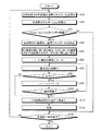
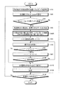
図1から図6を参照して、実施形態について説明する。本実施形態は、ハイブリッド車両用制御装置に関する。図1は、本発明の実施形態の制御に係るフローチャート、図2は、実施形態に係る車両のブロック図である。
[Embodiment]
The embodiment will be described with reference to FIGS. 1 to 6. The present embodiment relates to a hybrid vehicle control device. FIG. 1 is a flowchart according to the control of the embodiment of the present invention, and FIG. 2 is a block diagram of the vehicle according to the embodiment.
本実施形態に係るハイブリッド車両用制御装置1−1は、この先の交通状況を先読みし、EV走行/HV走行を切り替えるシステムを有する。ハイブリッド車両用制御装置1−1は、EV走行に適した区間を順に決めていくにあたり、各区間の消費エネルギーも考慮してEV区間を決定する。これにより、EV区間の設定をより適切なものとして、走行計画の最適化を図ることができる。 The hybrid vehicle control device 1-1 according to the present embodiment has a system that pre-reads the traffic situation ahead and switches between EV travel / HV travel. When determining the sections suitable for EV traveling in order, the hybrid vehicle control device 1-1 determines the EV sections in consideration of the energy consumption of each section. As a result, it is possible to optimize the travel plan by setting the EV section more appropriately.
図2に示すように、車両100は、動力源としてエンジン1および回転機2を有するハイブリッド(HV)車両である。車両100は、外部の電源により充電可能なプラグインハイブリッド(PHV)車両であってもよい。車両100は、上記の動力源に加えて、GPS10、車載カメラ11、ミリ波レーダ12、加速度センサ13、車速センサ14、表示装置15、ハイブリッドECU16、電池アクチュエータ17、ECU20、記憶部21、カーナビゲーション装置22、ブレーキアクチュエータ23、アクセルアクチュエータ24および通信装置25を含んで構成されている。また、本実施形態に係るハイブリッド車両用制御装置1−1は、回転機2、ECU20、およびカーナビゲーション装置22を含んで構成されている。なお、車両100には、エンジン1に代えて他の機関が搭載されてもよい。
As shown in FIG. 2,
回転機2は、モータ(電動機)としての機能と、発電機としての機能とを備えている。回転機2は、インバータを介してバッテリと接続されている。回転機2は、バッテリから供給される電力を機械的な動力に変換して出力することができると共に、入力される動力によって駆動されて機械的な動力を電力に変換することができる。回転機2によって発電された電力は、バッテリに蓄電可能である。回転機2としては、例えば、交流同期型のモータジェネレータを用いることができる。
The
車両100は、エンジン1を動力源として走行するHV走行モードと、回転機2を動力源として走行するEV走行モードとを有する。HV走行モードでは、エンジン1に加えて回転機2を動力源として走行することができる。EV走行モードでは、エンジン1を停止させて走行することができる。
GPS10は、複数のGPS衛星から送信される信号に基づいて車両100の位置を検出する。車載カメラ11は、車両100の周囲を撮像するカメラであり、例えば車両100の前方や後方を撮像して画像データを生成する。ミリ波レーダ12は、車両100の周辺の物体を検知する装置である。ミリ波レーダ12は、例えば、車両100と前方の車両との車間距離や車両100と後方の車両との車間距離を検出することができる。
The GPS 10 detects the position of the
加速度センサ13は、車両100の加速度を検出する。加速度センサ13は、例えば、車両100の前後方向の加速度や横方向の加速度等を検出する。車速センサ14は、車両100の走行速度を検出する。表示装置15は、運転者に対して伝達する情報を表示するものであり、走行計画を運転者に対して通知する通知手段として機能することができる。表示装置15は、例えば、ディスプレーやメーターとすることができる。電池アクチュエータ17は、バッテリを制御する。電池アクチュエータ17は、バッテリの充放電を制御することにより、バッテリから回転機2に供給する電流や回転機2からバッテリに充電する電流を制御することができる。また、電池アクチュエータ17は、バッテリの充電状態SOC(バッテリ残量Eev)を取得する。
The
GPS10、車載カメラ11、ミリ波レーダ12、加速度センサ13、および車速センサ14はそれぞれECU20と電気的に接続されており、検出したデータを示す信号をECU20に出力する。また、表示装置15および電池アクチュエータ17は、ECU20と電気的に接続されており、ECU20によって制御される。
The GPS 10, the in-
記憶部21は、メモリ等の記憶装置であり、ECU20での各種処理に必要な条件やデータ、ECU20で実行する各種プログラムが記憶されている。また、記憶部21は、地図情報データベース21aを有する。地図情報データベース21aは、車両100の走行に必要な情報(地図、直線路、カーブ、登降坂、高速道路、サグ、トンネルなど)が記憶されている。また、地図情報データベース21aは、地図データファイル、交差点データファイル、ノードデータファイル、道路データファイルを備えている。ECU20は、地図情報データベース21aを参照して、必要な情報を読み出す。
The storage unit 21 is a storage device such as a memory, and stores conditions and data necessary for various processes in the ECU 20 and various programs executed by the ECU 20. The storage unit 21 has a map information database 21a. The map information database 21a stores information (map, straight road, curve, uphill / downhill, highway, sag, tunnel, etc.) necessary for the
カーナビゲーション装置22は、車両100を所定の目的地に誘導する装置である。カーナビゲーション装置22は、ECU20と双方向の通信が可能である。カーナビゲーション装置22は、出発地から目的地までの走行経路を検出する検出装置としての機能を有している。カーナビゲーション装置22は、表示部を備えており、地図情報データベース21aに記憶されている情報や、GPS10で取得した現在地(現在位置)の情報に基づいて、周辺の地図情報を表示部に表示する。また、カーナビゲーション装置22は、地図情報データベース21aに記憶されている情報と、GPS10で取得した現在地の情報と、運転者等により入力された目的地(目的位置)の情報とから目的地までの経路を検出し、検出した経路情報を表示部に表示させる。カーナビゲーション装置22の表示部は、運転者に対して走行計画を通知する通知手段として機能することができる。ECU20は、カーナビゲーション装置22から案内経路に関する情報を取得することができる。なお、カーナビゲーション装置22は、地図情報データベース21aとGPS10とは別に自機に地図情報データベースとGPS通信部とを備え、自機の各部を用いて経路案内や、現在地情報の通知を行うようにしてもよい。
The
ブレーキアクチュエータ23は、車両100に搭載されたブレーキ装置の駆動を制御するものである。ブレーキアクチュエータ23は、例えば、ブレーキ装置に設けられるホイールシリンダの油圧を制御する。ブレーキアクチュエータ23は、ECU20に電気的に接続され、ECU20により動作が制御される。ECU20は、ブレーキ制御信号に応じてブレーキアクチュエータ23を作動し、ホイールシリンダのブレーキ油圧を調整する。言い換えれば、ブレーキアクチュエータ23は、ブレーキによる制動力を自動制御するための装置であり、ECU20から出力されるブレーキ制御信号を受信してホイールシリンダに作動油を供給する機構のソレノイドやモータなどを駆動させることでブレーキ油圧を制御し所望とする制動力を発生させる。このようにしてブレーキアクチュエータ23は、車両100に作用する制動力を制御することで、減速度を調節する。
The
アクセルアクチュエータ24は、エンジン1、回転機2等の車両100の動力源の出力を制御するものである。アクセルアクチュエータ24は、例えば、エンジン1への吸気量、吸気タイミングや点火タイミングを制御することができる。また、アクセルアクチュエータ24は、回転機2に対して供給する電流値等を制御することができる。アクセルアクチュエータ24は、ECU20に電気的に接続され、ECU20により動作が制御される。
The accelerator actuator 24 controls the output of the power source of the
ハイブリッドECU16およびECU20は、コンピュータを有する電子制御ユニットである。ハイブリッドECU16は、車両100の走行モードを選択する機能や、エンジン1および回転機2の出力トルクを決定する機能を有する。ハイブリッドECU16は、車両100の走行モードとして、HV走行モードあるいはEV走行モードを選択する。ハイブリッドECU16は、例えば、車両100に対する要求駆動力や要求パワー、要求トルク等に基づいて走行モードを決定することができる。また、ハイブリッドECU16は、後述する走行計画に基づいて走行モードを選択することができる。
The hybrid ECU 16 and the ECU 20 are electronic control units having a computer. The hybrid ECU 16 has a function of selecting a travel mode of the
ハイブリッドECU16は、HV走行モードで走行する場合、エンジン1に出力させるトルク(エンジントルク)と回転機2に出力させるトルク(MGトルク)を決定し、ECU20に対してエンジントルクの指令値およびMGトルクの指令値を出力する。ECU20は、エンジントルクの指令値を実現するように、アクセルアクチュエータ24によってエンジン1を制御する。また、ECU20は、MGトルクの指令値を実現するように、アクセルアクチュエータ24によって回転機2を制御する。
When the hybrid ECU 16 travels in the HV travel mode, the hybrid ECU 16 determines a torque (engine torque) to be output to the
ハイブリッドECU16は、EV走行モードで走行する場合、回転機2に出力させるトルクを決定し、ECU20に対してMGトルクの指令値を出力する。ハイブリッドECU16は、車両100が複数の回転機2を搭載している場合、各回転機2の出力トルクの指令値をそれぞれ決定する。
When the hybrid ECU 16 travels in the EV travel mode, the hybrid ECU 16 determines a torque to be output to the
ECU20は、エンジントルクの指令値に応じてアクセルアクチュエータ24を作動し、エンジン1への吸気量、吸気タイミングや点火タイミングを制御する。また、ECU20は、MGトルクの指令値に応じてアクセルアクチュエータ24を作動し、回転機2に供給する電流値等を調整する。言い換えれば、アクセルアクチュエータ24は、動力源による駆動力を自動制御するための装置であり、ECU20から出力される制御信号を受信して各部を駆動させることで駆動条件を制御し所望とする駆動力を発生させる。このようにしてアクセルアクチュエータ24は、車両100に作用する駆動力を制御することで、加速度を調節する。
The ECU 20 operates the accelerator actuator 24 according to the command value of the engine torque, and controls the intake amount, intake timing and ignition timing to the
通信装置25は、図示しない交通情報通信基地局と無線で通信するものである。通信装置25は、交通情報通信基地局から送信された道路交通情報を取得し、取得した道路交通情報をECU20に送信する。交通情報通信基地局から送信される道路交通情報は、例えば、現在や将来の渋滞に関する情報、走行経路上の区間における現在の平均車速や将来の平均車速の予測値に関する情報、交通規制に関する情報、天候に関する情報、路面状態に関する情報等が含まれる。通信装置25は、通信可能な交通情報通信基地局と常に通信を行い、道路交通情報を取得してもよいし、一定時間間隔で交通情報通信基地局と通信を行い、道路交通情報を取得してもよい。通信装置25は、例えば、DSRC(Dedicated Short Range Communications)により通信を行う。
The
本実施形態のECU20は、設定された走行経路をEV走行モードで走行するEV区間あるいはHV走行モードで走行するHV区間に区分けした走行計画を作成する計画制御を実施する。設定された走行経路とは、例えば、カーナビゲーション装置22によって設定された案内経路であり、現在地から運転者によって入力された目的地までの経路である。なお、設定された走行経路は、入力された目的地までの案内経路に代えて、例えば、推定された走行経路であってもよい。例えば、同じルートを巡回する車両の場合、その巡回ルートを推定経路として走行計画を作成することが可能である。また、通勤や通学用に使用される車両の場合、通勤経路や通学経路を走行計画の作成対象とする走行経路として設定可能である。本実施形態の計画制御によれば、この先の経路上の走行負荷を先読みし、EV走行モードとHV走行モードを最適に切り替える支援を行うことができる。本明細書では、走行計画に基づいて走行モードを選択する制御をモード選択支援制御とも記載する。
The ECU 20 of the present embodiment performs plan control for creating a travel plan that divides the set travel route into an EV section that travels in the EV travel mode or an HV section that travels in the HV travel mode. The set travel route is, for example, a guide route set by the
ECU20は、走行経路をEV区間あるいはHV区間に区分けする。従って、走行経路は、少なくとも1つの区間に区分けされる。地図情報データベース21aは、道路上に設定されたノード点の位置情報とIDを含むノードデータを記憶している。また、地図情報データベース21aは、ノード点を連結するリンクのIDを含むリンクデータを記憶している。リンクデータには、例えば、道路種別、勾配、平均曲率などが含まれる。ECU20は、リンクデータから、当該リンクに係る区間を走行する際の予測走行パワーや予測消費エネルギーを算出することができ、予測走行パワーや予測消費エネルギーに基づいて当該区間をEV区間とするかHV区間とするかを決定することができる。 The ECU 20 divides the travel route into EV sections or HV sections. Accordingly, the travel route is divided into at least one section. The map information database 21a stores node data including position information and IDs of node points set on the road. In addition, the map information database 21a stores link data including IDs of links that connect node points. The link data includes, for example, road type, gradient, average curvature, and the like. The ECU 20 can calculate predicted travel power and predicted energy consumption when traveling in the section related to the link from the link data, and determines whether the section is an EV section based on the predicted travel power and predicted consumption energy. It can be determined whether to be a section.
ハイブリッドECU16は、設定された走行経路を走行する場合に、ECU20によって作成された走行計画が有効とされていれば、その走行計画に基づいて走行モードを選択する。すなわち、車両100の現在地を含む区間がHV区間であれば、HV走行モードが選択され、車両100の現在地を含む区間がEV区間であればEV走行モードが選択される。ただし、走行モードの選択にあたっては、運転者の要求を優先することが好ましい。例えば、運転者の要求駆動力を実現できる走行モードがHV走行モードに限られる場合、走行計画でEV区間に設定されている区間であってもHV走行モードが選択されることが好ましい。
When the hybrid ECU 16 travels the set travel route, if the travel plan created by the ECU 20 is valid, the hybrid ECU 16 selects a travel mode based on the travel plan. That is, if the section including the current location of the
作成された走行計画や現在の状態は、例えば、表示装置15やカーナビゲーション装置22の画面に表示される。一例として、カーナビゲーション装置22の画面上に表示される案内経路において、各区間に割り当てられた走行モードが表示されてもよい。また、現在選択されている走行モードが表示装置15やカーナビゲーション装置22に表示されてもよい。走行計画が表示されることで、運転者はこの先のモード選択支援制御の内容を把握して運転することができる。
The created travel plan and the current state are displayed on the screen of the
ここで、走行計画をより適切に作成できることが望ましい。例えば、EV区間の設定において、区間における消費エネルギーである区間エネルギーEnを考慮しない場合、以下に図3および図4を参照して説明するように、計画していたEV区間に到達する前にバッテリ残量がなくなり、EV走行を実行できなくなる可能性がある。 Here, it is desirable to be able to create a travel plan more appropriately. For example, in the setting of the EV section, when the section energy En, which is the energy consumption in the section, is not taken into account, as described below with reference to FIGS. 3 and 4, the battery is set before reaching the planned EV section. There is a possibility that the remaining amount runs out and EV traveling cannot be executed.
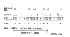
図3は、各区間の走行負荷および区間エネルギーEnの一例を示す図、図4は、区間エネルギーEnを考慮せずに設定された走行計画の一例を示す図である。図3には、出発地から目的地までの走行経路上の区間Aから区間Kまでの各区間について、走行負荷、区間エネルギーEnおよび負荷による順位が示されている。区間エネルギーEnは、区間を走行するときに消費する電力量を表すものであり、例えば、区間をEV走行モードで走行する間のバッテリの放電量である。区間エネルギーEnは、バッテリ残量と共通の所定のエネルギー単位で示されている。例えば、区間AをEV走行した場合、バッテリのエネルギーが2単位消費される。負荷による順位は、区間の走行負荷が小さい順に付している。すなわち、区間Eの走行負荷が最も小さく、区間H、区間K、区間Aの順に走行負荷が大きくなる。 FIG. 3 is a diagram illustrating an example of the travel load and the segment energy En in each section, and FIG. 4 is a diagram illustrating an example of the travel plan set without considering the section energy En. FIG. 3 shows ranks according to travel load, section energy En, and load for each section from section A to section K on the travel route from the departure point to the destination. The section energy En represents the amount of power consumed when traveling in the section, and is, for example, the amount of battery discharge while traveling in the EV traveling mode in the section. The section energy En is shown in a predetermined energy unit common to the battery remaining amount. For example, when EV traveling in the section A, 2 units of battery energy are consumed. The ranking by load is given in ascending order of travel load in the section. That is, the traveling load of the section E is the smallest, and the traveling load increases in the order of the section H, the section K, and the section A.
EV区間の区間エネルギーEnの総和をEV区間総消費エネルギーEと称する。本実施形態では、EV区間総消費エネルギーEがバッテリ残量Eevを超えるまで、負荷による順位に従ってEV区間が選択されていく。負荷による順位に従って区間E、区間H、区間K、区間AまでEV区間に設定すると、EV区間総消費エネルギーEは8となり、バッテリ残量Eevと等しくなる。負荷による順位が区間Aに次ぐ区間DまでEV区間に設定すると、EV区間総消費エネルギーEが11となり、バッテリ残量Eevよりも大となる。この場合、区間DまでEV区間に設定され、残る区間はHV区間に設定される。従って、走行負荷の小さな区間から順にEV区間を設定した場合に作成される走行計画は、図4に示すように、区間A,D,E,H,Kの5区間をEV区間に設定したものとなる。 The sum of the section energy En of the EV section is referred to as EV section total consumption energy E. In the present embodiment, the EV section is selected according to the order of the load until the EV section total energy consumption E exceeds the battery remaining amount Eev. If the EV section is set up to section E, section H, section K, and section A according to the order of load, the EV section total energy consumption E is 8, which is equal to the battery remaining amount Eev. When the rank according to the load is set to the EV section until the section D subsequent to the section A, the EV section total energy consumption E becomes 11, which is larger than the battery remaining amount Eev. In this case, the EV section is set up to the section D, and the remaining section is set as the HV section. Therefore, as shown in FIG. 4, the travel plan created when EV sections are set in order from the section with the smallest travel load is one in which sections A, D, E, H, and K are set as EV sections. It becomes.
ところが、図4に示す走行計画に従って走行すると、区間Kに到達する前にバッテリ残量Eevがなくなってしまい、区間KではEV走行を実行することができなくなる。区間Dは、負荷による順位が低いにもかかわらず、区間エネルギーEnが大きい。区間Dにおいて多くのエネルギーが消費されてしまうため、区間Hを走行している途中にバッテリ残量Eevがなくなり、区間KでEV走行ができなくなってしまう。相対的にEV適度Mnが高い(走行負荷が低い)区間Kが前方に存在するにもかかわらず、EV適度Mnが低い区間Dで多くのバッテリ残量Eevを低下させてしまうことは好ましくない。 However, if the vehicle travels according to the travel plan shown in FIG. 4, the remaining battery level Eev disappears before reaching the section K, and EV traveling cannot be executed in the section K. In the section D, the section energy En is large even though the rank according to the load is low. Since a lot of energy is consumed in the section D, the remaining battery level Eev disappears while traveling in the section H, and EV traveling in the section K becomes impossible. Although there is a section K in the front where the EV moderate Mn is relatively high (traveling load is low), it is not preferable that the battery remaining amount Eev is decreased in the section D where the EV moderate Mn is low.
本実施形態に係るハイブリッド車両用制御装置1−1は、走行経路上の区間ごとに、EV走行モードに適している度合を表すEV適度、および走行時に消費する電力量を表す消費エネルギーを算出し、EV適度と、消費エネルギーと、電池アクチュエータ17が検出したバッテリの残量とに基づいて走行経路上におけるEV走行モードを行うEV区間を計画する走行計画制御を実行する。ハイブリッド車両用制御装置1−1は、走行計画制御において、走行経路上の複数の区間のうちEV適度の高い区間から順にEV区間に設定し、EV適度が同程度の区間に対しては、消費エネルギーの小さい区間から順にEV区間に設定する。 The hybrid vehicle control device 1-1 according to the present embodiment calculates, for each section on the travel route, a moderate EV that indicates the degree of suitability for the EV travel mode, and energy consumption that represents the amount of power consumed during travel. Then, the travel plan control for planning the EV section in which the EV travel mode is performed on the travel route is executed based on the moderate EV, the consumed energy, and the remaining battery level detected by the battery actuator 17. In the travel plan control, the hybrid vehicle control device 1-1 sets EV sections in order from a section with a high EV among a plurality of sections on the travel route. The EV section is set in order from the section with the smallest energy.
また、ハイブリッド車両用制御装置1−1は、走行計画制御において、EV区間に設定される区間の消費エネルギーの総和がバッテリの残量を超えるまでEV区間を設定する。これにより、バッテリ残量Eevを有効に利用してEV走行距離やEV走行時間を最大限に設定することが可能となる。 Further, the hybrid vehicle control device 1-1 sets the EV section in the travel plan control until the sum of energy consumption in the section set as the EV section exceeds the remaining amount of the battery. This makes it possible to set the EV travel distance and EV travel time to the maximum by effectively using the remaining battery charge Eev.
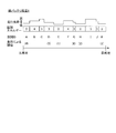
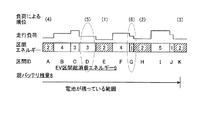
図5は、本実施形態に係る走行計画を示す図、図6は、実施形態に係る区間の並べ替えの説明図である。図6の上欄には、走行負荷の大きさに従った区間の順位が示されている。区間E、区間H、区間Kの順に走行負荷が大きくなる。本実施形態のハイブリッド車両用制御装置1−1は、走行負荷に基づいて区間のEV適度Mnのレベル分けを行う。例えば、EV適度Mnが最も高いレベル5から最も低いレベル1まで5段階のレベル分けがなされる。同じレベルに属する区間は、EV適度Mnが同程度の区間である。図3に示す走行経路では、区間A,E,H,Kが最も適度の高いレベル(EV適度5)に分類される。区間D,Gは、次に適度の高いレベル(EV適度4)に分類される。
FIG. 5 is a diagram illustrating a travel plan according to the present embodiment, and FIG. 6 is an explanatory diagram of rearrangement of sections according to the embodiment. The upper column of FIG. 6 shows the ranks of the sections according to the magnitude of the traveling load. The travel load increases in the order of section E, section H, and section K. The hybrid vehicle control device 1-1 according to the present embodiment classifies EV moderate Mn levels in the section based on the travel load. For example, the level is divided into five stages from
同一のEV適度の中では、区間エネルギーEnの小さい順に並べ替えがなされる。EV適度5の中では、全ての区間(区間A,E,H,K)の区間エネルギーEnが2で同一である。この場合、例えば、他の指標(出発地に近い順、区間長が短い順等)に従って並べ替えがなされる。EV適度4の中では、区間Dの区間エネルギーEnが3であり、区間Gの区間エネルギーEnが1である。従って、EV適度4の中で区間G,区間Dの順に並べ替えがなされる。 In the same EV mode, rearrangement is performed in ascending order of the interval energy En. In EV moderate 5, the section energy En of all the sections (sections A, E, H, K) is 2 and the same. In this case, for example, the rearrangement is performed according to other indices (in order of proximity to the departure place, in order of shorter section length, etc.). In the EV moderate 4, the section energy En of the section D is 3, and the section energy En of the section G is 1. Therefore, rearrangement is performed in the order of the section G and the section D in the EV moderate 4.
従って、本実施形態では、図5に示すように、区間Dに代えて、区間Gが5番目にEV区間に設定される。これにより、EV区間は区間A,E,G,H,Kの5区間となり、EV区間総消費エネルギーEは9となる。モード選択支援制御が実行されると、区間Hを走行し終えた時点でバッテリ残量Eevが1であり、区間KにおいてEV走行を実行することができる。従って、本実施形態に係るハイブリッド車両用制御装置1−1によれば、走行計画に従った走行ができなくなることを抑制することができる。本実施形態に係るハイブリッド車両用制御装置1−1は、走行計画をより適切なものとすることができる。また、本実施形態に係るハイブリッド車両用制御装置1−1は、モード選択支援制御のエネルギーマネジメントの最適化を図ることができる。 Therefore, in the present embodiment, as shown in FIG. 5, instead of the section D, the section G is set as the fifth EV section. Thereby, the EV section becomes five sections A, E, G, H, and K, and the EV section total consumption energy E is 9. When the mode selection support control is executed, the battery remaining amount Eev is 1 at the end of traveling in the section H, and the EV traveling can be performed in the section K. Therefore, according to the hybrid vehicle control device 1-1 according to the present embodiment, it is possible to prevent the vehicle from traveling according to the travel plan. The hybrid vehicle control device 1-1 according to the present embodiment can make the travel plan more appropriate. Moreover, the hybrid vehicle control device 1-1 according to the present embodiment can optimize the energy management of the mode selection support control.
図1を参照して、本実施形態に係る制御について説明する。図1に示す制御フローは、例えば、イグニッションがONとされているときや、ハイブリッドシステムが作動しているときに所定の間隔で繰り返し実行される。なお、図1に示す制御フローは、目的地が入力されているときに限り実行されてもよい。 The control according to the present embodiment will be described with reference to FIG. The control flow shown in FIG. 1 is repeatedly executed at predetermined intervals, for example, when the ignition is turned on or when the hybrid system is operating. Note that the control flow shown in FIG. 1 may be executed only when a destination is input.
まず、ステップS10では、ECU20により、目的地までの各区間の消費エネルギー(区間エネルギー)Enが算出される。目的地までの走行経路は、例えば、走行負荷や道路種別等に基づいて複数の区間に分けられている。例えば、地図情報データベース21aや通信装置25から取得する情報(勾配、道路種別、平均走行速度等)に基づいて、走行経路上における走行負荷の変動幅が所定以下の連続する範囲がそれぞれ一つの区間として設定される。図3に示す例では、出発地を始点とする比較的走行負荷が低い連続した部分が区間Aとされ、その後の走行負荷が中程度の連続する部分が区間Bとされ、その後の走行負荷が高い連続する部分が区間Cとされ、同様にして区間Kまでの各区間が設定される。ECU20は、走行負荷等に基づいて、各区間をEV走行モードで走行した場合のEV走行用バッテリの消費エネルギーを区間エネルギーEnとして算出する。ステップS10が実行されると、ステップS20に進む。
First, in step S10, the ECU 20 calculates energy consumption (section energy) En for each section to the destination. The travel route to the destination is divided into a plurality of sections based on, for example, the travel load and the road type. For example, based on information (gradient, road type, average travel speed, etc.) acquired from the map information database 21a or the
ステップS20では、ECU20により、全消費エネルギーEsumが算出される。ECU20は、ステップS10で算出された各区間の区間エネルギーEnの総和を全消費エネルギーEsumとして算出する。本実施形態では、全消費エネルギーEsumは、所定のエネルギー単位で算出される。 In step S20, the ECU 20 calculates the total energy consumption Esum. ECU20 calculates the sum total of the section energy En of each section calculated by step S10 as total consumption energy Esum. In the present embodiment, the total consumed energy Esum is calculated in a predetermined energy unit.
次に、ステップS30では、ECU20により、全消費エネルギーEsumがバッテリ残量Eevよりも大であるか否かが判定される。ECU20は、電池アクチュエータ17から、現在のEV走行用バッテリのバッテリ残量Eevを取得する。ここで、バッテリ残量Eevはエネルギーであり、本実施形態では所定のエネルギー単位で表される。ステップS30の判定の結果、全消費エネルギーEsumがバッテリ残量Eevよりも大であると判定された場合(ステップS30−Y)にはステップS40に進み、そうでない場合(ステップS30−N)にはステップS130に進む。 Next, in step S30, the ECU 20 determines whether or not the total consumed energy Esum is larger than the battery remaining amount Eev. The ECU 20 acquires the current remaining battery level Eev of the EV traveling battery from the battery actuator 17. Here, the battery remaining amount Eev is energy, and is expressed in a predetermined energy unit in the present embodiment. As a result of the determination in step S30, when it is determined that the total consumed energy Esum is larger than the battery remaining amount Eev (step S30-Y), the process proceeds to step S40, and otherwise (step S30-N). Proceed to step S130.
ステップS40では、ECU20により、各区間のEV適度Mnおよび区間エネルギーEnが算出される。ECU20は、走行経路上の各区間のEV適度Mnを算出する。本実施形態のEV適度Mnは、走行負荷であり、一例として区間の平均走行負荷である。また、区間エネルギーEnは、ステップS10で算出される値と同様とすることができる。 In step S40, the ECU 20 calculates the EV moderate Mn and the section energy En for each section. The ECU 20 calculates the EV moderate Mn for each section on the travel route. EV moderate Mn of this embodiment is a running load, and is an average running load of a section as an example. Further, the section energy En can be the same as the value calculated in step S10.
次に、ステップS50では、ECU20により、区間の並べ替えがなされる。ECU20は、ステップS40で算出されたEV適度Mnに基づいて、図6を参照して説明したように、EV適度Mnによる区間の並べ替えを行い、更に、同一EV適度Mnの中では区間エネルギーEnの小さい順に区間の並べ替えを行う。EV区間の設定に際しては、図6の下欄に示す順序と同様の順序、すなわち区間エネルギーEnを考慮した順位に従って、EV区間が選択される。全ての区間の並べ替えが完了すると、ステップS60に進む。 Next, in step S50, the ECU 20 rearranges the sections. Based on the EV moderate Mn calculated in step S40, the ECU 20 rearranges the sections based on the EV moderate Mn as described with reference to FIG. 6, and further, in the same EV moderate Mn, the section energy En. Sort the sections in ascending order. When setting the EV section, the EV section is selected according to the same order as the order shown in the lower column of FIG. 6, that is, the order considering the section energy En. When rearrangement of all sections is completed, the process proceeds to step S60.
ステップS60では、ECU20により、最初の区間(区間番号i=0)の区間エネルギーEnがEV区間総消費エネルギーEに代入される。図6の例では、区間Eの区間エネルギーEnの値である2がEV区間総消費エネルギーEに代入される。ステップS60が実行されると、ステップS70に進む。 In step S60, the ECU 20 substitutes the section energy En of the first section (section number i = 0) into the EV section total consumption energy E. In the example of FIG. 6, 2 which is the value of the section energy En of the section E is substituted into the EV section total consumed energy E. When step S60 is executed, the process proceeds to step S70.
ステップS70では、ECU20により、現在の区間番号iの区間がEV区間に設定される。例えば、最初にステップS70が実行される場合、図6下欄の並び順に従うと、区間番号i=0である区間EがEV区間に設定される。ステップS70が実行されると、ステップS80に進む。 In step S70, the section of the current section number i is set as the EV section by the ECU 20. For example, when step S70 is first executed, according to the order of arrangement in the lower column of FIG. 6, the section E with the section number i = 0 is set as the EV section. When step S70 is executed, the process proceeds to step S80.
ステップS80では、ECU20により、EV区間総消費エネルギーEがバッテリ残量Eev以下であるか否かが判定される。ステップS80の判定の結果、EV区間総消費エネルギーEがバッテリ残量Eev以下であると判定された場合(ステップS80−Y)にはステップS90に進み、そうでない場合(ステップS80−N)にはステップS110に進む。図6下欄の並び順に従うと、区間AをEV区間に設定した段階(i=3)ではEV区間総消費エネルギーEが8、バッテリ残量Eevも8であるため、ステップS80で肯定判定がなされてステップS90に進む。一方、区間GをEV区間に設定した後(i=4)ではEV区間総消費エネルギーEが9であるため、ステップS80で否定判定がなされてステップS110に進む。 In step S80, the ECU 20 determines whether the EV section total consumed energy E is equal to or less than the battery remaining amount Eev. As a result of the determination in step S80, when it is determined that the EV section total consumed energy E is equal to or less than the battery remaining amount Eev (step S80-Y), the process proceeds to step S90, and otherwise (step S80-N). Proceed to step S110. According to the arrangement order in the lower column of FIG. 6, since EV section total energy consumption E is 8 and battery remaining amount Eev is 8 at the stage where section A is set to EV section (i = 3), an affirmative determination is made in step S80. Then, the process proceeds to step S90. On the other hand, after the section G is set as the EV section (i = 4), the EV section total consumed energy E is 9, so a negative determination is made in step S80 and the process proceeds to step S110.
ステップS90では、ECU20により、区間番号iおよびEV区間総消費エネルギーEが更新される。ECU20は、区間番号iに1を加算する。また、ECU20は、EV区間総消費エネルギーEに区間番号iの区間の区間エネルギーEnを加算する。例えば、最初にステップS90が実行される場合、図6下欄の並び順に従うと、区間番号i=1である区間Hの区間エネルギーEnの値2がEV区間総消費エネルギーEに加算される。なお、区間番号iに相当する区間が存在しない場合、EV区間総消費エネルギーEに0が加算される。ステップS90が実行されると、ステップS100に進む。
In step S90, the ECU 20 updates the section number i and the EV section total energy consumption E. The ECU 20 adds 1 to the section number i. Further, the ECU 20 adds the section energy En of the section with the section number i to the EV section total consumption energy E. For example, when step S90 is first executed, the
ステップS100では、ECU20により、区間番号iが総区間数の番号よりも大であるか否かが判定される。例えば、図3に示す走行経路の場合、総区間数は11であり、最後の区間の区間番号はi=10である。従って、区間番号i=10以下であればステップS100で否定判定がなされ、区間番号i=11であれば肯定判定がなされる。ステップS100の判定の結果、区間番号iが総区間数の番号よりも大であると判定された場合(ステップS100−Y)にはステップS110に進み、そうでない場合(ステップS100−N)にはステップS70に移行する。 In step S100, the ECU 20 determines whether the section number i is greater than the total number of sections. For example, in the case of the travel route shown in FIG. 3, the total number of sections is 11, and the section number of the last section is i = 10. Accordingly, if the section number i = 10 or less, a negative determination is made in step S100, and if the section number i = 11, an affirmative determination is made. As a result of the determination in step S100, if it is determined that the section number i is larger than the total number of sections (step S100-Y), the process proceeds to step S110, and if not (step S100-N). Control goes to step S70.
ステップS110では、ECU20により、EV区間以外の区間に対してHV走行が割り当てられる。ECU20は、既にEV区間に設定された区間以外の区間をHV区間に設定する。図5に示すように、EV区間に設定されなかった区間B,C,D,F,I,JがHV区間に設定される。ステップS110が実行されると、ステップS120に進む。 In step S110, the ECU 20 assigns HV traveling to a section other than the EV section. The ECU 20 sets a section other than the section already set as the EV section as the HV section. As shown in FIG. 5, sections B, C, D, F, I, and J that are not set in the EV section are set in the HV section. When step S110 is executed, the process proceeds to step S120.
ステップS120では、ECU20により、支援が実行される。ECU20は、モード選択支援制御を実行し、作成された走行計画に応じて、各区間において走行モードを決定する。ステップS120が実行されると、ステップS130に進む。 In step S120, the ECU 20 performs support. The ECU 20 executes mode selection support control, and determines the travel mode in each section according to the created travel plan. When step S120 is executed, the process proceeds to step S130.
ステップS130では、ECU20により、支援終了条件が成立したか否かが判定される。支援終了条件は、例えば、目的地に到着したこと、EV走行用バッテリの電池残量がなくなったこと、支援を終了するドライバの意思を示す操作を検知したことなどである。ステップS130の判定の結果、支援終了条件が成立したと判定された場合(ステップS130−Y)には本制御フローは終了し、そうでない場合(ステップS130−N)にはステップS10に移行する。 In step S130, the ECU 20 determines whether or not a support end condition is satisfied. The support end condition is, for example, that the vehicle has reached the destination, that the remaining battery level of the EV traveling battery is exhausted, or that an operation indicating the driver's intention to end support is detected. As a result of the determination in step S130, if it is determined that the support end condition is satisfied (step S130-Y), the control flow ends. If not (step S130-N), the process proceeds to step S10.
以上説明したように、本実施形態に係るハイブリッド車両用制御装置1−1によれば、EV適度Mnが同程度の区間に対しては、区間エネルギーEnの小さい区間から順にEV区間に設定される。よって、本実施形態に係るハイブリッド車両用制御装置1−1は、走行計画の適切さを向上することができるという効果を奏する。例えば、前方にEV適度Mnのより高い区間が存在するにもかかわらず、その区間に到達する前にバッテリ残量Eevがなくなってしまうといった問題の発生が抑制される。 As described above, according to the hybrid vehicle control device 1-1 according to the present embodiment, EV sections are set to EV sections in order from the section with the smallest section energy En for sections with the same EV moderate Mn. . Therefore, the hybrid vehicle control device 1-1 according to the present embodiment has an effect of improving the suitability of the travel plan. For example, although there is a section with a higher EV moderate Mn in front, the occurrence of a problem that the remaining battery level Eev disappears before reaching the section is suppressed.
[実施形態の第1変形例]
実施形態の第1変形例について説明する。上記実施形態では、区間の並べ替えにおいて、同一EV適度の中では区間エネルギーEnの小さい順に並べ替えがなされた。実施形態の第1変形例では、区間エネルギーEnに代えて、区間長に基づいて並べ替えがなされる。
[First Modification of Embodiment]
A first modification of the embodiment will be described. In the above embodiment, in the rearrangement of the sections, the rearrangement is performed in ascending order of the section energy En in the same EV mode. In the first modification of the embodiment, rearrangement is performed based on the section length instead of the section energy En.
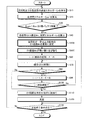
図7は、実施形態の第1変形例の制御に係るフローチャートである。第1変形例では、上記実施形態(図1)のステップS50に代えて、ステップS50Aが実行される。ステップS50Aでは、ECU20により、区間の並び替えがなされる。ECU20は、ステップS40で算出されたEV適度Mnの高い順に区間を並べ替える。ただし、同一EV適度の中では、区間長が短い順に並べ替えがなされる。区間長が短い区間では区間エネルギーEnが小さくなりやすく、区間長が長い区間では区間エネルギーEnが大きくなりやすい。よって、第1変形例の制御によれば、バッテリ残量Eevの不足によりEV区間でEV走行を実行できなくなることが抑制され、走行計画の適切さを向上することができる。 FIG. 7 is a flowchart according to the control of the first modification of the embodiment. In the first modification, step S50A is executed instead of step S50 in the embodiment (FIG. 1). In step S50A, the ECU 20 rearranges the sections. The ECU 20 rearranges the sections in descending order of EV moderate Mn calculated in step S40. However, in the same EV mode, rearrangement is performed in ascending order of section length. The section energy En tends to be small in a section having a short section length, and the section energy En is likely to be large in a section having a long section length. Therefore, according to the control of the first modification, it is possible to prevent the EV traveling from being executed in the EV section due to the shortage of the battery remaining amount Eev, and the suitability of the travel plan can be improved.
なお、区間長に代えて、区間時間に基づく並べ替えがなされてもよい。区間時間は、それぞれの区間を走行するために要する時間である。同一EV適度の中では、区間時間が短い順に区間の並べ替えがなされる。その他、区間エネルギーEnに関連するパラメータに基づいて区間の並べ替えがなされてもよい。 Note that rearrangement based on section time may be performed instead of section length. The section time is the time required to travel in each section. Within the same EV mode, the sections are rearranged in order from the shortest section time. In addition, the sections may be rearranged based on the parameters related to the section energy En.
[実施形態の第2変形例]
実施形態の第2変形例について説明する。実施形態の第2変形例では、EV区間の選択において、区間長が長い区間の優先度が下げられる。図8は、実施形態の第2変形例の制御に係るフローチャートである。第2変形例では、上記実施形態(図1)のステップS50に代えて、ステップS50BおよびS50Cが実行される。
[Second Modification of Embodiment]
A second modification of the embodiment will be described. In the second modification of the embodiment, in selecting an EV section, the priority of a section having a long section length is lowered. FIG. 8 is a flowchart according to the control of the second modified example of the embodiment. In the second modified example, steps S50B and S50C are executed instead of step S50 in the embodiment (FIG. 1).
ステップS50Bでは、ECU20により、区間長が一定以上の区間のEV適度Mnが最低に設定される。ECU20は、区間長が所定以上の区間に対して、走行負荷の大きさにかかわらず、EV適度Mnを最低に設定する。これにより、所定以上の区間長を有する区間は、EV区間の割り当てにおける優先順位が低くなる。ステップS50Bが実行されると、ステップS50Cに進む。 In step S50B, the ECU 20 sets the EV moderate Mn for the section having a certain section length or more to the minimum. ECU20 sets EV moderate Mn to the minimum with respect to the area where area length is more than predetermined regardless of the magnitude | size of driving | running | working load. As a result, a section having a section length greater than or equal to a predetermined value has a lower priority in EV section allocation. When step S50B is executed, the process proceeds to step S50C.
ステップS50Cでは、ECU20により、EV適度Mnの高い順に区間の並べ替えがなされる。ステップS50Cが実行されると、ステップS60に進み、EV区間の割り当てが開始される。 In step S50C, the ECU 20 sorts the sections in descending order of EV moderate Mn. When step S50C is executed, the process proceeds to step S60, and allocation of EV sections is started.
本変形例によれば、相対的に区間長の短い区間が優先してEV区間に設定される。これにより、全てのEV区間に行き着く前にバッテリ残量Eevが無くなってしまうような走行計画が作成されることを抑制することができる。 According to this modification, a section having a relatively short section length is preferentially set as the EV section. Thereby, it is possible to suppress the creation of a travel plan in which the remaining battery level Eev is lost before reaching all EV sections.
なお、ステップS50Bにおいて、区間長が一定以上の区間のEV適度Mnを低くすることに代えて、区間エネルギーEnが一定以上の区間のEV適度Mnを低くするようにしてもよい。 In step S50B, instead of lowering EV moderate Mn in a section having a certain section length or more, EV moderate Mn in a section having section energy En or more may be lowered.
また、ステップS50Cにおいて、更に、同一EV適度Mnの中で区間の並べ替えがなされてもよい。例えば、区間エネルギーEnが小さい順や区間長が短い順に区間の並べ替えがなされてもよい。 In step S50C, the sections may be rearranged in the same EV moderate Mn. For example, the sections may be rearranged in order from the smallest section energy En or from the smallest section length.
また、区間長が所定以上に長い区間や区間エネルギーEnが所定以上の区間はEV区間の設定対象から除外されるようにしてもよい。例えば、バッテリ残量Eevに対する区間エネルギーEnの割合が所定以上である区間をEV区間の設定対象から除外するようにしてもよい。 Further, a section having a section length longer than a predetermined length or a section having a section energy En greater than a predetermined number may be excluded from the EV section setting targets. For example, a section in which the ratio of the section energy En to the battery remaining amount Eev is equal to or greater than a predetermined value may be excluded from the EV section setting targets.
[実施形態の第3変形例]
上記実施形態では、走行負荷に応じて区間がレベル分けされ、EV適度Mnが同一レベルの区間に対して区間エネルギーEnに基づく並べ替えがなされたが、並べ替え方法はこれに限定されるものではない。例えば、予めEV適度Mnをレベル分けすることに代えて、以下に説明するように、並べ替えを行う際に走行負荷が同程度の区間を抽出し、抽出された区間を区間エネルギーEnの小さい順に並べ替えるようにしてもよい。
[Third Modification of Embodiment]
In the above embodiment, the sections are classified according to the travel load, and the EV moderate Mn is rearranged based on the section energy En for the same level, but the rearrangement method is not limited to this. Absent. For example, instead of dividing EV moderate Mn into levels in advance, as described below, when rearranging, sections having the same traveling load are extracted, and the extracted sections are in order of increasing section energy En. You may make it rearrange.
例えば、図3に示す走行経路についてEV区間を設定する場合、始めに最も走行負荷が小さい側から走行負荷が同程度の区間を抽出する。例えば、最も走行負荷が小さい区間Eの走行負荷に対して走行負荷の差が所定範囲内の区間が抽出される。これにより、例えば区間E、区間H、区間Kが抽出されたとすると、これらの3区間を区間エネルギーEnの小さい順に並べ替え、EV区間総消費エネルギーEがバッテリ残量Eevよりも大きくなるまで順にEV区間に設定していく。 For example, when the EV section is set for the travel route shown in FIG. 3, a section having the same travel load is first extracted from the side having the smallest travel load. For example, a section in which the difference in travel load is within a predetermined range with respect to the travel load in section E with the smallest travel load is extracted. Thus, for example, if section E, section H, and section K are extracted, these three sections are rearranged in ascending order of section energy En, and EV section total energy consumption E is sequentially increased until the battery remaining amount Eev becomes larger. Set to the interval.
区間E,H,Kの3区間をEV区間に設定してもEV区間総消費エネルギーEがバッテリ残量Eev以下であれば、更に、残る区間の最も走行負荷が小さい側から走行負荷が同程度の区間を抽出する。これにより、例えば、区間A、区間D、区間Gが抽出されたとすると、これらの3区間を区間エネルギーEnの小さい順に並べ替え、EV区間総消費エネルギーEがバッテリ残量Eevよりも大きくなるまで順にEV区間に設定していく。以降は同様の工程を繰り返して、EV区間総消費エネルギーEがバッテリ残量Eevよりも大きくなるまでEV区間を設定していく。このようにしても、EV適度Mnが同程度の区間を区間エネルギーEnの小さい順にEV区間に設定することができる。 Even if the three sections E, H, and K are set as EV sections, if the EV section total energy consumption E is less than or equal to the remaining battery level Eev, the remaining sections have the same traveling load from the side with the smallest traveling load. This section is extracted. Thus, for example, if section A, section D, and section G are extracted, these three sections are rearranged in order of decreasing section energy En, and in order until EV section total energy consumption E becomes larger than battery remaining amount Eev. Set to EV section. Thereafter, the same process is repeated, and the EV section is set until the EV section total energy consumption E becomes larger than the battery remaining amount Eev. Even in this case, a section having the same EV moderate Mn can be set as the EV section in ascending order of the section energy En.
[実施形態の第4変形例]
実施形態の第4変形例について説明する。上記実施形態および各変形例では、EV適度Mnが走行負荷であったが、これには限定されない。例えば、区間を走行するときのEV走行の効率とHV走行の効率との比であるEV/HV効率比やエンジン効率等のパラメータや、複数のパラメータの組み合わせに基づいてEV適度が算出されてもよい。
[Fourth Modification of Embodiment]
A fourth modification of the embodiment will be described. In the said embodiment and each modification, EV moderate Mn was driving | running | working load, However, It is not limited to this. For example, even if the EV appropriateness is calculated based on a parameter such as an EV / HV efficiency ratio, an engine efficiency, or the like, which is a ratio between the efficiency of EV traveling and the efficiency of HV traveling when traveling in a section, or a combination of a plurality of parameters. Good.
上記の実施形態および各変形例に開示された内容は、適宜組み合わせて実行することができる。 The contents disclosed in the above embodiment and each modification can be executed in appropriate combination.
1−1 ハイブリッド車両用制御装置
1 エンジン
2 回転機
16 ハイブリッドECU
20 ECU
100 車両
E EV区間総消費エネルギー
Eev バッテリ残量
Mn EV適度
1-1 Hybrid
20 ECU
100 Vehicle E EV section total energy consumption Eev Battery level Mn EV moderate
Claims (2)
前記回転機を動力源として走行するEV走行モードと、
出発地から目的地までの走行経路を検出する検出装置と、
を備え、
前記走行経路上の区間ごとに、前記EV走行モードに適している度合を表すEV適度、および走行時に消費する電力量を表す消費エネルギーを算出し、
前記EV適度は、少なくとも走行負荷、EV/HV効率比、およびエンジン効率を含むパラメータおよび該パラメータの組み合わせに基づいて算出され、
前記EV適度と、前記消費エネルギーと、検出したバッテリの残量とに基づいて前記走行経路上における前記EV走行モードを行うEV区間を計画する走行計画制御を実行し、
前記走行計画制御において、前記走行経路上の複数の区間のうち前記EV適度の高い区間から順に前記EV区間に設定し、前記EV適度が同程度の区間に対しては、前記消費エネルギーの小さい区間から順に前記EV区間に設定する
ことを特徴とするハイブリッド車両用制御装置。 A rotating machine that outputs power by electric power supplied from a battery;
EV traveling mode in which the rotating machine travels as a power source;
A detection device for detecting a travel route from the departure point to the destination;
With
For each section on the travel route, calculate an EV moderate degree representing the degree of suitability for the EV travel mode, and energy consumption representing the amount of power consumed during travel,
The EV moderate is calculated based on a parameter including at least a traveling load, an EV / HV efficiency ratio, and an engine efficiency and a combination of the parameters,
Executing travel plan control for planning an EV section for performing the EV travel mode on the travel route on the basis of the moderate EV, the consumed energy, and the remaining battery level detected;
In the travel plan control, the EV section is set in order from the section with a high EV among the plurality of sections on the travel route, and the section with the low energy consumption is set for the section with the same EV moderate. The hybrid vehicle control device is characterized in that the EV section is set in order from.
請求項1に記載のハイブリッド車両用制御装置。 2. The hybrid vehicle control device according to claim 1, wherein in the travel plan control, the EV section is set until a total sum of the consumed energy of the section set as the EV section exceeds a remaining amount of the battery.
Priority Applications (1)
| Application Number | Priority Date | Filing Date | Title |
|---|---|---|---|
| JP2013032392A JP6020249B2 (en) | 2013-02-21 | 2013-02-21 | Control device for hybrid vehicle |
Applications Claiming Priority (1)
| Application Number | Priority Date | Filing Date | Title |
|---|---|---|---|
| JP2013032392A JP6020249B2 (en) | 2013-02-21 | 2013-02-21 | Control device for hybrid vehicle |
Publications (2)
| Publication Number | Publication Date |
|---|---|
| JP2014162261A JP2014162261A (en) | 2014-09-08 |
| JP6020249B2 true JP6020249B2 (en) | 2016-11-02 |
Family
ID=51613312
Family Applications (1)
| Application Number | Title | Priority Date | Filing Date |
|---|---|---|---|
| JP2013032392A Expired - Fee Related JP6020249B2 (en) | 2013-02-21 | 2013-02-21 | Control device for hybrid vehicle |
Country Status (1)
| Country | Link |
|---|---|
| JP (1) | JP6020249B2 (en) |
Families Citing this family (13)
| Publication number | Priority date | Publication date | Assignee | Title |
|---|---|---|---|---|
| JP6028781B2 (en) * | 2014-10-14 | 2016-11-16 | トヨタ自動車株式会社 | Information processing apparatus for vehicle |
| JP6489054B2 (en) * | 2016-03-30 | 2019-03-27 | トヨタ自動車株式会社 | Hybrid car |
| KR20190003046A (en) * | 2017-06-30 | 2019-01-09 | 현대자동차주식회사 | Hybrid vehicle and method of changing operation mode for the same |
| JP6981262B2 (en) * | 2018-01-10 | 2021-12-15 | トヨタ自動車株式会社 | Hybrid vehicle |
| US11560136B2 (en) | 2018-03-02 | 2023-01-24 | Toyota Jidosha Kabushiki Kaisha | Control device |
| JP7067388B2 (en) * | 2018-03-02 | 2022-05-16 | トヨタ自動車株式会社 | Hybrid vehicle control device |
| JP6939689B2 (en) | 2018-04-19 | 2021-09-22 | トヨタ自動車株式会社 | Hybrid vehicle control device |
| JP6958470B2 (en) * | 2018-04-19 | 2021-11-02 | トヨタ自動車株式会社 | Hybrid vehicle control device |
| JP6927133B2 (en) | 2018-04-19 | 2021-08-25 | トヨタ自動車株式会社 | Hybrid vehicle control device |
| JP7067387B2 (en) | 2018-09-21 | 2022-05-16 | トヨタ自動車株式会社 | Hybrid vehicle control device |
| JP7115218B2 (en) * | 2018-10-26 | 2022-08-09 | トヨタ自動車株式会社 | hybrid vehicle |
| JP2020066388A (en) * | 2018-10-26 | 2020-04-30 | トヨタ自動車株式会社 | Hybrid vehicle |
| JP2025055834A (en) * | 2023-09-27 | 2025-04-08 | トヨタ自動車株式会社 | Hybrid Vehicles |
Family Cites Families (5)
| Publication number | Priority date | Publication date | Assignee | Title |
|---|---|---|---|---|
| JP3610879B2 (en) * | 2000-04-28 | 2005-01-19 | 株式会社日立製作所 | Hybrid vehicle |
| JP4089325B2 (en) * | 2002-07-17 | 2008-05-28 | アイシン・エィ・ダブリュ株式会社 | Hybrid vehicle control system |
| JP4123143B2 (en) * | 2003-11-28 | 2008-07-23 | 株式会社エクォス・リサーチ | Hybrid vehicle control device and hybrid vehicle |
| JP5330812B2 (en) * | 2008-11-20 | 2013-10-30 | トヨタ自動車株式会社 | Hybrid vehicle |
| JP2011020571A (en) * | 2009-07-16 | 2011-02-03 | Nissan Motor Co Ltd | Device for controlling hybrid vehicle |
-
2013
- 2013-02-21 JP JP2013032392A patent/JP6020249B2/en not_active Expired - Fee Related
Also Published As
| Publication number | Publication date |
|---|---|
| JP2014162261A (en) | 2014-09-08 |
Similar Documents
| Publication | Publication Date | Title |
|---|---|---|
| JP6020249B2 (en) | Control device for hybrid vehicle | |
| CN105143009B (en) | Traveling supports device, traveling support method and drive assist system | |
| US9200917B2 (en) | Vehicle control device | |
| CN109466537B (en) | Vehicle and method for controlling vehicle | |
| CN109747619B (en) | Vehicle and method of controlling the vehicle | |
| CN109383505B (en) | System and method for determining efficient driving speed of a vehicle | |
| JP4702086B2 (en) | Vehicle driving support device | |
| CN105008005B (en) | Travel support device, travel support method, and drive support system | |
| KR102575153B1 (en) | Optimization method for driving of electric vehicle | |
| CN103930662B (en) | driving support device | |
| JP5929866B2 (en) | Movement support device, movement support method, and driving support system | |
| JP6007929B2 (en) | Movement support device, movement support method, and driving support system | |
| JP7589700B2 (en) | Hybrid electric vehicle and control method thereof | |
| JP7234562B2 (en) | CONTROL METHOD AND CONTROL DEVICE FOR HYBRID VEHICLE | |
| KR102033988B1 (en) | Hybrid vehicle | |
| JP2008082944A (en) | VEHICLE DISPLAY DEVICE, VEHICLE DISPLAY DEVICE CONTROL METHOD, PROGRAM, AND RECORDING MEDIUM CONTAINING THE PROGRAM | |
| JP2011062014A (en) | In-vehicle charging/discharging controller and partial controller included in the same | |
| JPWO2016038680A1 (en) | Control device for hybrid vehicle | |
| JP2016097697A (en) | Information processing apparatus for vehicle | |
| JP2013237290A (en) | Display control device, vehicle control device and vehicle | |
| JP2018079728A (en) | Hybrid vehicle | |
| JP5900371B2 (en) | Control device for hybrid vehicle | |
| JP6136976B2 (en) | Movement support device, movement support method, and driving support system | |
| JP4802715B2 (en) | Temperature rise prediction device, route guidance system including the same, vehicle equipped with the same, temperature rise prediction method, route guidance method, and thermal load prediction device | |
| JP2013207847A (en) | Control device of vehicle, and vehicle equipped with the same |
Legal Events
| Date | Code | Title | Description |
|---|---|---|---|
| A621 | Written request for application examination |
Free format text: JAPANESE INTERMEDIATE CODE: A621 Effective date: 20150423 |
|
| A977 | Report on retrieval |
Free format text: JAPANESE INTERMEDIATE CODE: A971007 Effective date: 20160307 |
|
| A131 | Notification of reasons for refusal |
Free format text: JAPANESE INTERMEDIATE CODE: A131 Effective date: 20160315 |
|
| A521 | Request for written amendment filed |
Free format text: JAPANESE INTERMEDIATE CODE: A523 Effective date: 20160415 |
|
| TRDD | Decision of grant or rejection written | ||
| A01 | Written decision to grant a patent or to grant a registration (utility model) |
Free format text: JAPANESE INTERMEDIATE CODE: A01 Effective date: 20160906 |
|
| A61 | First payment of annual fees (during grant procedure) |
Free format text: JAPANESE INTERMEDIATE CODE: A61 Effective date: 20160919 |
|
| R151 | Written notification of patent or utility model registration |
Ref document number: 6020249 Country of ref document: JP Free format text: JAPANESE INTERMEDIATE CODE: R151 |
|
| LAPS | Cancellation because of no payment of annual fees |