JP4702086B2 - Vehicle driving support device - Google Patents
Vehicle driving support device Download PDFInfo
- Publication number
- JP4702086B2 JP4702086B2 JP2006038098A JP2006038098A JP4702086B2 JP 4702086 B2 JP4702086 B2 JP 4702086B2 JP 2006038098 A JP2006038098 A JP 2006038098A JP 2006038098 A JP2006038098 A JP 2006038098A JP 4702086 B2 JP4702086 B2 JP 4702086B2
- Authority
- JP
- Japan
- Prior art keywords
- vehicle
- deceleration
- point
- brake
- vehicle speed
- Prior art date
- Legal status (The legal status is an assumption and is not a legal conclusion. Google has not performed a legal analysis and makes no representation as to the accuracy of the status listed.)
- Expired - Fee Related
Links
Images


Classifications
-
- B—PERFORMING OPERATIONS; TRANSPORTING
- B60—VEHICLES IN GENERAL
- B60L—PROPULSION OF ELECTRICALLY-PROPELLED VEHICLES; SUPPLYING ELECTRIC POWER FOR AUXILIARY EQUIPMENT OF ELECTRICALLY-PROPELLED VEHICLES; ELECTRODYNAMIC BRAKE SYSTEMS FOR VEHICLES IN GENERAL; MAGNETIC SUSPENSION OR LEVITATION FOR VEHICLES; MONITORING OPERATING VARIABLES OF ELECTRICALLY-PROPELLED VEHICLES; ELECTRIC SAFETY DEVICES FOR ELECTRICALLY-PROPELLED VEHICLES
- B60L7/00—Electrodynamic brake systems for vehicles in general
- B60L7/10—Dynamic electric regenerative braking
- B60L7/14—Dynamic electric regenerative braking for vehicles propelled by ac motors
-
- B—PERFORMING OPERATIONS; TRANSPORTING
- B60—VEHICLES IN GENERAL
- B60L—PROPULSION OF ELECTRICALLY-PROPELLED VEHICLES; SUPPLYING ELECTRIC POWER FOR AUXILIARY EQUIPMENT OF ELECTRICALLY-PROPELLED VEHICLES; ELECTRODYNAMIC BRAKE SYSTEMS FOR VEHICLES IN GENERAL; MAGNETIC SUSPENSION OR LEVITATION FOR VEHICLES; MONITORING OPERATING VARIABLES OF ELECTRICALLY-PROPELLED VEHICLES; ELECTRIC SAFETY DEVICES FOR ELECTRICALLY-PROPELLED VEHICLES
- B60L1/00—Supplying electric power to auxiliary equipment of vehicles
- B60L1/02—Supplying electric power to auxiliary equipment of vehicles to electric heating circuits
-
- B—PERFORMING OPERATIONS; TRANSPORTING
- B60—VEHICLES IN GENERAL
- B60L—PROPULSION OF ELECTRICALLY-PROPELLED VEHICLES; SUPPLYING ELECTRIC POWER FOR AUXILIARY EQUIPMENT OF ELECTRICALLY-PROPELLED VEHICLES; ELECTRODYNAMIC BRAKE SYSTEMS FOR VEHICLES IN GENERAL; MAGNETIC SUSPENSION OR LEVITATION FOR VEHICLES; MONITORING OPERATING VARIABLES OF ELECTRICALLY-PROPELLED VEHICLES; ELECTRIC SAFETY DEVICES FOR ELECTRICALLY-PROPELLED VEHICLES
- B60L58/00—Methods or circuit arrangements for monitoring or controlling batteries or fuel cells, specially adapted for electric vehicles
- B60L58/10—Methods or circuit arrangements for monitoring or controlling batteries or fuel cells, specially adapted for electric vehicles for monitoring or controlling batteries
- B60L58/12—Methods or circuit arrangements for monitoring or controlling batteries or fuel cells, specially adapted for electric vehicles for monitoring or controlling batteries responding to state of charge [SoC]
- B60L58/15—Preventing overcharging
-
- B—PERFORMING OPERATIONS; TRANSPORTING
- B60—VEHICLES IN GENERAL
- B60L—PROPULSION OF ELECTRICALLY-PROPELLED VEHICLES; SUPPLYING ELECTRIC POWER FOR AUXILIARY EQUIPMENT OF ELECTRICALLY-PROPELLED VEHICLES; ELECTRODYNAMIC BRAKE SYSTEMS FOR VEHICLES IN GENERAL; MAGNETIC SUSPENSION OR LEVITATION FOR VEHICLES; MONITORING OPERATING VARIABLES OF ELECTRICALLY-PROPELLED VEHICLES; ELECTRIC SAFETY DEVICES FOR ELECTRICALLY-PROPELLED VEHICLES
- B60L2250/00—Driver interactions
- B60L2250/16—Driver interactions by display
-
- Y—GENERAL TAGGING OF NEW TECHNOLOGICAL DEVELOPMENTS; GENERAL TAGGING OF CROSS-SECTIONAL TECHNOLOGIES SPANNING OVER SEVERAL SECTIONS OF THE IPC; TECHNICAL SUBJECTS COVERED BY FORMER USPC CROSS-REFERENCE ART COLLECTIONS [XRACs] AND DIGESTS
- Y02—TECHNOLOGIES OR APPLICATIONS FOR MITIGATION OR ADAPTATION AGAINST CLIMATE CHANGE
- Y02T—CLIMATE CHANGE MITIGATION TECHNOLOGIES RELATED TO TRANSPORTATION
- Y02T10/00—Road transport of goods or passengers
- Y02T10/60—Other road transportation technologies with climate change mitigation effect
- Y02T10/70—Energy storage systems for electromobility, e.g. batteries
Landscapes
- Engineering & Computer Science (AREA)
- Power Engineering (AREA)
- Transportation (AREA)
- Mechanical Engineering (AREA)
- Life Sciences & Earth Sciences (AREA)
- Sustainable Development (AREA)
- Sustainable Energy (AREA)
- Electric Propulsion And Braking For Vehicles (AREA)
- Regulating Braking Force (AREA)
Description
本発明は、ドライバーのブレーキ操作を支援する車両用運転支援装置に関する。 The present invention relates to a vehicle driving support device that supports a driver's brake operation.
従来から、燃費が向上するように、エンジンとモータを駆動源とするハイブリッド車両を制御する車両制御装置が知られている(例えば、特許文献1参照)。この車両制御装置は、ブレーキ操作を検出したときに、車両の現在位置から進行先に減速・停止が必要な地点が存在するか否かを地図情報から検索し、減速・停止が必要な地点が存在するならば、現在位置とその減速・停止必要地点との距離に基づいて減速を行うように自動変速機の変速段を低く選択するものである。これによって、モータの回転数を高くして、回生制動により多くのエネルギーを回収可能にして、燃費向上を図ろうとしている。
しかしながら、上述の従来技術では、ドライバーがブレーキペダルの操作をしなければ、減速・停止の必要な地点を検索して、自動変速機の変速段を選択することを開始しないので、ブレーキ操作が遅いドライバーでは、モータの回転数が高くなるタイミングが遅れたり、回生制動する時間が短くなったりするため、燃費向上を効果的行うことが困難な場合があった。また、ドライバーはどのようにブレーキを操作すれば燃費向上に寄与するのかを知ることができなかった。 However, in the above-described prior art, if the driver does not operate the brake pedal, searching for a point where deceleration / stop is necessary and starting to select the gear position of the automatic transmission are not started, so the brake operation is slow. For the driver, there are cases where it is difficult to improve fuel efficiency effectively because the timing at which the rotational speed of the motor increases is delayed or the time for regenerative braking is shortened. Also, the driver could not know how to operate the brakes to improve fuel efficiency.
そこで、本発明は、燃費向上に寄与する回生ブレーキが作動するようにドライバーのブレーキ操作を誘導することができる車両用運転支援装置の提供を目的とする。 Accordingly, an object of the present invention is to provide a vehicle driving support device that can guide a driver's brake operation so that a regenerative brake that contributes to an improvement in fuel efficiency is activated.
上記課題を解決するため、本発明として、
車両の位置を検出する位置検出手段と、
要減速地点の地図情報を記憶する記憶手段と、
前記位置検出手段により検出された車両位置に基づき進行方向に位置する要減速地点の地図情報を前記記憶手段から抽出する抽出手段と、
前記抽出手段によって抽出された要減速地点の地図情報に基づいて、その要減速地点における目標車速を設定する目標車速設定手段と、
現在車速から前記目標車速設定手段によって設定された目標車速まで回生ブレーキで減速する場合に必要な減速距離を算出する減速距離算出手段と、
前記抽出手段によって地図情報が抽出された要減速地点と前記減速距離算出手段によって算出された減速距離とに基づいてブレーキ操作の開始が必要なブレーキ開始点を案内する案内手段を備える、車両用運転支援装置を提供する。
In order to solve the above problems, as the present invention,
Position detecting means for detecting the position of the vehicle;
Storage means for storing map information of the deceleration point required;
Extracting means for extracting from the storage means the map information of the decelerating points required in the traveling direction based on the vehicle position detected by the position detecting means;
Target vehicle speed setting means for setting a target vehicle speed at the required deceleration point based on the map information of the required deceleration point extracted by the extraction means;
A deceleration distance calculating means for calculating a deceleration distance required when decelerating with a regenerative brake from a current vehicle speed to a target vehicle speed set by the target vehicle speed setting means;
Driving for a vehicle, comprising guidance means for guiding a brake start point where a brake operation needs to be started based on a deceleration required point where map information is extracted by the extraction means and a deceleration distance calculated by the deceleration distance calculation means A support device is provided.
ここで、前記ブレーキ開始点は、前記抽出手段によって地図情報が抽出された要減速地点から前記減速距離算出手段によって算出された減速距離分手前に位置する地点であると好適である。 Here, it is preferable that the brake start point is a point located before the deceleration distance calculated by the deceleration distance calculation unit from the deceleration point where map information is extracted by the extraction unit.
また、前記案内手段は、前記抽出手段によって地図情報が抽出された要減速地点から前記減速距離算出手段によって算出された減速距離分手前に位置する地点に車両が到達した場合にブレーキ操作の案内を開始すると好適である。 Further, the guide means guides the brake operation when the vehicle reaches a point located before the deceleration distance calculated by the deceleration distance calculation means from the deceleration point where the map information is extracted by the extraction means. It is preferred to start.
さらに、前記案内手段は、ドライバーのブレーキ操作量を案内することが好適であり、前記ブレーキ操作量を視覚的に案内する表示手段であるとさらに好適である。 Further, it is preferable that the guide means guides a brake operation amount of a driver, and it is further preferable that the guide means is a display means for visually guiding the brake operation amount.
また、前記減速距離算出手段によって算出された減速距離は、前記車両の走行状態に基づいて補正されることが好適であり、前記走行状態として、周辺車両の状態や天候状態が挙げられる。 The deceleration distance calculated by the deceleration distance calculating means is preferably corrected based on the traveling state of the vehicle, and examples of the traveling state include a state of a surrounding vehicle and a weather state.
本発明によれば、燃費向上に寄与する回生ブレーキが作動するようにドライバーのブレーキ操作を誘導することができる。 According to the present invention, it is possible to guide the driver's brake operation so that the regenerative brake that contributes to the improvement of fuel consumption is activated.
以下、図面を参照して、本発明を実施するための最良の形態の説明を行う。図1は、本実施形態の車両用運転支援装置を適用したハイブリッド車両システムのブロック図の一例である。 The best mode for carrying out the present invention will be described below with reference to the drawings. FIG. 1 is an example of a block diagram of a hybrid vehicle system to which the vehicle driving support device of this embodiment is applied.
内燃機関であるエンジン20の運転は、ECU(Electronic Control Unit)10により制御されている。ECU10は、シフトポジションセンサやアクセルポジションセンサ等からのセンサ信号に基づいてトータルトルクを算出する。ECU10は、算出されたトータルトルクに対し、所望の駆動力配分比に従い、エンジン要求回転数やエンジン要求トルクといったエンジン出力要求値などを算出して、必要に応じて、エンジン20や動力分割機構22やインバータ26などの制御を実行する。
The operation of the
動力分割機構22は、エンジン20の出力をディファレンシャル32に伝達して車輪を駆動させることができ、また、エンジン20の出力をジェネレータ24に伝達して発電させることができる。動力分割機構22は、エンジン20の出力を、ディファレンシャル32とジェネレータ24に所望の駆動力配分比で振り分ける。つまり、動力分割機構22は、その配分比に応じて、エンジン20のみを駆動源とする「エンジン走行」をさせたり、ジェネレータ24を介して後述するモータ30のみを駆動源とする「モータ走行」をさせたり、エンジン20とモータ30を駆動源とする「エンジン+モータ走行」をさせたりすることができる。
The
ジェネレータ24は、エンジン20の出力やディファレンシャル32の運動エネルギーを使用して発電する。この発電によって、ジェネレータ24は、インバータ26を介してバッテリ28を充電したり、モータ30の駆動用の電力供給を行ったりする。
The
モータ30は、インバータ26内の三相ブリッジ回路等により駆動され、エンジン20とは異なる駆動源として車輪を回転させる。また、回生ブレーキ作動時には、モータ30は、運動エネルギーを電気エネルギーに変換し、インバータ26を介してバッテリ28を充電する。
The
ナビゲーション装置7は、GPS装置と地図DB(データベース)を有している。GPS装置は、GPS受信機によるGPS衛星からの受信情報に基づいて、自車の位置を2次元若しくは3次元の座標データによって特定する装置である。一方、地図DBは、高精度の地図情報を記憶している。高精度の地図情報には、減速が必要な地点(要減速地点)として、三叉路をはじめとする交差点、踏切、有料道路の料金所などの一時停止が必要な地点の情報がその地点の座標データとともに含まれている。また、その地図情報には、要減速地点として、必ずしも一時停止が必要ではない地点、すなわち、カーブやETC(Electronic Toll Collection)レーンなどの地点情報もその地点の座標データとともに含まれている。また、車車間通信や路車間通信や管理センター等の車外との通信を介して、渋滞情報などを取得することによって、渋滞している地点を要減速地点としてその地図情報に反映してもよい。また、座標データだけでなく、カーブの半径や曲率やカント、路面勾配、道路の車線数や車線幅や停止線の詳細位置、右折/左折レーン、標高、法定速度等の通過可能速度といった要減速地点に関する詳細な数値情報が含まれていてもよい。 The navigation device 7 has a GPS device and a map DB (database). The GPS device is a device that specifies the position of the vehicle by two-dimensional or three-dimensional coordinate data based on information received from a GPS satellite by a GPS receiver. On the other hand, the map DB stores high-precision map information. High-accuracy map information includes information on points that need to be temporarily stopped, such as intersections including three-way intersections, railroad crossings, and tollgates on toll roads as points that require deceleration (deceleration points required). Is included. In addition, the map information includes a point that does not necessarily need to be temporarily stopped as a deceleration required point, that is, point information such as a curve or an ETC (Electronic Toll Collection) lane together with the coordinate data of the point. In addition, by acquiring traffic jam information, etc. via vehicle-to-vehicle communication, road-to-vehicle communication, or communication with outside the vehicle such as a management center, the traffic congestion point may be reflected in the map information as a deceleration point required. . In addition to the coordinate data, deceleration required such as curve radius, curvature, cant, road slope, road lane number, lane width, detailed position of stop line, right / left turn lane, altitude, legal speed, etc. Detailed numerical information regarding the point may be included.
ナビゲーション装置7は、GPS装置により検出された車両位置に基づいて車両の進行している方向に位置する要減速地点に関する座標データなどの地図情報を地図DBから抽出する。ナビゲーション装置7は、抽出した地図情報や車両位置情報などをECU10に送信する。
The navigation device 7 extracts map information such as coordinate data relating to a deceleration point required in the direction in which the vehicle is traveling from the map DB based on the vehicle position detected by the GPS device. The navigation device 7 transmits the extracted map information, vehicle position information, and the like to the
なお、ナビゲーション装置7は、乗員の操作を受け付けるユーザ操作入力部や、乗員に対して情報を提供する情報提供部を有していてもよい。ユーザ操作入力部は、スイッチ操作やタッチパネル操作や音声入力等によって、ユーザからのナビゲーション装置7に対する指示情報を受け付ける。情報提供部は、ディスプレイ表示や音声出力等のユーザが認識可能な態様によって、ナビゲーション装置7から提供される情報をユーザに伝達する。例えば、ナビゲーション装置7は、ユーザ操作入力部を介してこれから向かう目的地が設定されると、GPS装置により特定された現在地点と地図DB内の地図情報とに基づいて目的地までの走行経路を探索し、情報提供部を介して走行経路の探索結果を乗員に提供することができる。 In addition, the navigation apparatus 7 may have a user operation input unit that receives an occupant's operation and an information providing unit that provides information to the occupant. The user operation input unit receives instruction information for the navigation device 7 from the user by a switch operation, a touch panel operation, a voice input, or the like. The information providing unit transmits information provided from the navigation device 7 to the user in a manner that can be recognized by the user, such as display display or voice output. For example, the navigation device 7 sets the travel route to the destination based on the current location specified by the GPS device and the map information in the map DB when the destination to be reached is set through the user operation input unit. It is possible to search and provide the passenger with the search result of the travel route through the information providing unit.
他の車両用ECU6は、ECU10が必要とする車両にかかわる走行状態を表す情報(具体例を挙げるならば、車速、エンジン回転数、ブレーキ信号、ウィンカ信号、カメラの撮像情報、周辺車両の走行状態、天候情報、エアコンの作動状態など)の送付元である。なお、ECU10は、車速センサからの車速信号など、車両の走行状態を検知するセンサから車両の走行状態を直接取得してもよいので、他の車両用ECU6とは、特にECUに限っているわけではない。 The other vehicular ECU 6 is information indicating a driving state related to the vehicle required by the ECU 10 (for example, vehicle speed, engine speed, brake signal, blinker signal, camera imaging information, driving state of surrounding vehicles) , Weather information, air conditioner operating status, etc.). The ECU 10 may directly acquire the traveling state of the vehicle from a sensor that detects the traveling state of the vehicle, such as a vehicle speed signal from a vehicle speed sensor, so that the other vehicle ECUs 6 are limited to the ECU in particular. is not.
また、他の車両用ECU6は、バッテリ28の電流値や電圧値を検出することによって、バッテリ28の容量がどれだけ残っているのかを示す「残容量(SOC:State of Charge)」を算出する。他の車両用ECU6は、例えば、バッテリ28の充放電電流の積算(積分)などにより残容量を算出する。電気量(バッテリ28の容量)の時間的変化の割合が、電流に相当するからである。残容量はバッテリ28の満充電時の容量からバッテリ28から放電された放電量を引いた値に相当することから、他の車両用ECU6は、バッテリ28に接続される電源ラインを電流センサ等によってバッテリ28の充放電電流をモニターしその履歴をメモリに記録することによって、残容量を算出することが可能になる。なお、満充電時の容量は、初期値としてメモリに記憶されている。
Further, the other vehicle ECU 6 detects a current value or a voltage value of the
また、他の車両用ECU6は、放電初期時のバッテリ28の電圧の極小値を測定することによって残容量を推定してもよい。放電初期時の電圧の落ち込みにより生じる極小値と残容量は相関があることが知られているため、他の車両用ECU6は、その相関関係(例えば、マップデータ)に基づいて残容量を推定することができる。
The other vehicle ECU 6 may estimate the remaining capacity by measuring the minimum value of the voltage of the
なお、バッテリ28が電気二重層キャパシタに置換可能であり、その静電容量が既知であるならば、他の車両用ECU6は、電気二重層キャパシタの電圧値と静電容量に基づいて電気二重層キャパシタの残容量を算出することができる。
If the
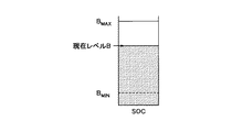
また、残容量は、図7に示されるような、上限値BMAXと下限値BMINに挟まれたSOC管理幅に保たれるように充放電の制御が実行される。SOC管理幅を設けることによって、例えば過度の充放電を原因とするバッテリ28の劣化の進行速度が速まるのを防ぐことができる。
Further, charge / discharge control is executed so that the remaining capacity is maintained within the SOC management range sandwiched between the upper limit value B MAX and the lower limit value B MIN as shown in FIG. By providing the SOC management range, for example, it is possible to prevent the progress of deterioration of the
したがって、モータ30によって回生ブレーキが行われた場合、その回生エネルギーはバッテリ28に充電されるが、上限値BMAXまでしか充電することはできない。超過分の回生エネルギーは、熱によって消費されたり、油圧ブレーキ等のメインの制動装置を作動させて上限値BMAXに収まる程度に抑えられたりする。言い換えれば、モータ30によって発生した回生エネルギーが上限値BMAXと現在の残容量Bとの差分値以下であれば、油圧ブレーキ等のメインの制動装置を作動させることなく、その発生した回生エネルギーの全てを使って回生ブレーキのみで減速することが可能となる。
Therefore, when regenerative braking is performed by the
なお、モータ30によって発生する回生エネルギーは次のように算出することができる。他の車両用ECU6は、ナビゲーション装置7からの情報に基づいて減速によって発生する回収可能なエネルギーを演算する。車速Vで走行する車両を目標車速Vminまで回生可能減速度α(例えば、0.2[m/s2])で減速する場合に、その車両の運動エネルギーの変化分を全て回生するとした場合の回収できるエネルギー△Bは、
[数1]
△B=0.5×M×(V2−Vmin2)×σ[J]
=2.78×10−7×0.5×M×(V2−Vmin2)×σ[kWh]
=Σ×(V2−Vmin2)[kWh]
と演算できる。なお、Mは車両重量[kg]、σはエネルギー回生効率[%]、Σは定数(=2.78×10−7×0.5×M×σ)である。つまり、△Bは車速Vを変数とする2次関数で定義することができる。もちろん、車速以外の走行状態の情報を反映した補正を行ってもよい。
The regenerative energy generated by the
[Equation 1]
ΔB = 0.5 × M × (V 2 −Vmin 2 ) × σ [J]
= 2.78 × 10 −7 × 0.5 × M × (V 2 −Vmin 2 ) × σ [kWh]
= Σ × (V 2 −Vmin 2 ) [kWh]
Can be calculated. M is the vehicle weight [kg], σ is the energy regeneration efficiency [%], and Σ is a constant (= 2.78 × 10 −7 × 0.5 × M × σ). That is, ΔB can be defined by a quadratic function with the vehicle speed V as a variable. Of course, correction reflecting information on the driving state other than the vehicle speed may be performed.
なお、回生可能減速度αとは、回生が見込める減速度であって、それ以上の減速度で減速した場合には回生されずに熱として消費されるエネルギーが増大することになる。また、回生可能減速度αは、モータ30の負荷や車両の状態によって物理的に決まってくる値である。
The regenerative deceleration α is a deceleration at which regeneration can be expected, and when the vehicle is decelerated at a deceleration higher than that, the energy consumed as heat increases without being regenerated. The regenerative deceleration α is a value that is physically determined by the load of the
ECU10は、ナビゲーション装置7によって抽出された進行方向に位置する要減速地点の地図情報に基づいて、その抽出された進行方向に位置する要減速地点における目標車速を設定する。要減速地点における目標車速は、各要減速地点における目標車速を予め定めておいて地図情報として記憶しておいてもよいし、ドライバーの個々の運転履歴から各要減速地点における目標車速を学習して地図情報に反映するようにしてもよい。また、減速地点が踏切や料金所等の予めその地点における車速が一律に決めることができるような地点であれば、減速地点における目標車速を地図情報に一律に設定しておくことも可能である(例えば、零あるいは所定の低車速値)。さらに、要減速地点がカーブの場合、カーブにおける目標車速はカーブの半径や勾配情報等に基づいて、安全走行可能な車速を演算する所定の演算式で算出した値を地図情報に反映するようにしてもよい。
The
また、ECU10は、車速センサ等によって検出された現在車速から上記設定した目標車速まで回生ブレーキのみで減速する場合に必要な制動距離(以下、「減速距離」という)を算出する。減速距離の算出は、例えば、バッテリ28に受け入れ可能なパワーを示す電池受け入れ可能パワーWinに基づいて行われるが、詳細は後述する。
Further, the
また、ECU10は、ナビゲーション装置7によって抽出された進行方向に位置する要減速地点の手前に位置する「ブレーキ開始地点」までの距離を算出する。ブレーキ開始地点までの距離は、進行方向に位置する要減速地点から上記算出した減速距離を引いた距離に相当する。ブレーキ開始地点までの算出距離が零ということは、車両がブレーキ開始地点に到達していることを意味する。これによって、例えば、ECU10は、ブレーキ開始地点に車両が到達した地点で、すなわち、ブレーキ開始地点までの距離が零になった地点で、案内装置40を使用してブレーキ操作の誘導・案内を開始することができる。
In addition, the
なお、ECU10は、エンジン20やモータ30等を制御するハイブリッド制御などの制御プログラムや制御データを記憶するROM、制御プログラムの処理データを一時的に記憶するRAM、制御プログラムを処理するCPU、外部と情報をやり取りするための入出力インターフェースなどの複数の回路要素によって構成されたものである。また、ECU10は一つの制御ユニットとは限らず、制御が分担されるように複数の制御ユニットであってよい。
The
案内装置40は、ECU10から指令に基づいて、ブレーキ操作の案内をドライバーに対して行う。案内装置40として、表示装置や音声出力装置などが挙げられる。表示装置は、メーター、フロントコンソールディスプレイ、ヘッドアップディスプレイ、ホログラフィ装置等であって、ユーザに対し視覚的な情報を通知する装置である。音声出力装置は、スピーカやイヤホン等であって、ユーザに対し聴覚的な音声情報を通知する装置である。
The
案内装置40は、ブレーキ操作の開始が必要なブレーキ開始点をドライバーに案内するとともに、燃費向上に寄与する回生ブレーキを維持したままの減速を可能にするブレーキ操作ができるようにドライバーを誘導する。ブレーキ開始点は、ブレーキ操作の開始が必要な「地点」として考えてもよいし、ブレーキ操作の開始が必要な「時点」として考えてもよい。
The
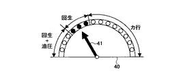
図2は、案内装置40の一具体例である。指針41の指示先が現在のモータ30の駆動状態に相当する。モータ30の駆動状態は、モータ30が車輪を駆動して走行している力行状態と、回生ブレーキ作動中の回生状態に分けられる。さらに、回生状態は、回生のみの単独状態と回生ブレーキとメインブレーキ(油圧ブレーキ)との併用状態に分けられる。上述の電池受け入れ可能パワーWinの値に応じて回生のみの単独状態の範囲は変化し、電池受け入れ可能パワーWinの値が大きくなるほど回生のみの単独状態の範囲は広くなる。それを明示するために、回生のみの単独状態を示す範囲のみにランプ(例えば、緑ランプ)を点灯させる(図2の3つの黒丸部分)。電池受け入れ可能パワーWinの値が大きくなるほど、図2の反時計回りにランプの点灯数が増える。
FIG. 2 is a specific example of the
また、指針41の指示先が併用状態になっているということは、ドライバーのブレーキ操作量(ブレーキペダルの踏力)が大きすぎて油圧ブレーキの作動により本来回生のみで回収可能なエネルギーを熱等で無駄に消費してしまっていることを示している。すなわち、ECU10からの指令に従い案内装置40は、回生可能減速度α以下の減速度となるブレーキ操作をしている場合には回生のみの単独状態を示す範囲(ランプ点灯範囲)を指示するように指針41を動かし、回生可能減速度αを超えた減速度となるブレーキ操作をしている場合には併用状態を示す範囲を指示するように指針41を動かす。
In addition, the fact that the indication point of the pointer 41 is in the combined state means that the driver's brake operation amount (braking force of the brake pedal) is too large, and the energy that can be recovered only by regenerative operation due to the operation of the hydraulic brake is due to heat, etc. It shows that it has been wasted. That is, in accordance with a command from the
しかし、ドライバーは、指針41の指示先によってモータ30の駆動状態を容易に把握することができるので、指針41の動きに応じてブレーキ操作量を調整することで、モータ30の駆動状態を回生のみの単独状態に容易に維持させることができる。さらに、回生のみの単独状態を示す範囲のみにランプを点灯させることによって、ドライバーの視認性は向上する。
However, since the driver can easily grasp the driving state of the
図2に示される案内装置40の場合、ブレーキ開始点までの距離が零になった地点に車両が到達すると、例えば、「ブレーキ操作を開始ください」と音声案内が行われるとともに、緑ランプが点灯や点滅をし始め、指針41が現在のモータ30の駆動状態を指示する。
In the case of the
それでは、本実施形態の車両用運転支援装置の動作について説明する。図4は、本実施形態の車両用運転支援装置の動作フローである。 Now, the operation of the vehicle driving support device of this embodiment will be described. FIG. 4 is an operation flow of the vehicle driving support apparatus of the present embodiment.
車速Vで走行する車両のECU10は、進行方向に要減速地点が存在するか否かを判断する(ステップ10)。要減速地点の存在可否を判断するために、ECU10は、まず、ナビゲーション装置7に対し、GPS装置により検出された現在の車両位置Psに基づいて経路案内機能を利用して車両の進行している方向に減速地点に関する座標データなどの地図情報が地図DBに記憶されているか否かを検索するように指示する。要減速地点が存在しなければ、本フローは終了する。要減速地点が存在するならば、ナビゲーション装置7は、抽出した要減速地点に関する地図情報をECU10に送信する。
The
ECU10は、ブレーキ操作の支援を禁止する条件に該当していないか否かを判断する(ステップ20)。ECU10は、例えば、追突防止のため、後続車が存在する場合にはブレーキ操作の支援を禁止する。レーダーや撮像装置等の車両の後方を監視する手段によって後続車との車間距離を監視し、後続車との車間距離が所定値以下になった場合にはブレーキ操作の支援を禁止する。ブレーキ操作の支援を禁止する条件に該当していなければ、ステップ30に移行する。
The
ECU10は、上述したように、ナビゲーション装置7によって抽出された進行方向に位置する要減速地点の地図情報に基づいて、その抽出された進行方向に位置する要減速地点における目標車速を設定する(ステップ30)。この際、ECU10は、ナビゲーション装置7からの情報を取得して、現在位置Psに基づき進行方向に位置する要減速地点における停止線等の目標停止位置Pgを設定する。目標停止位置Pgは、例えば、ナビゲーション装置7が抽出した要減速地点のうち車両と直近の要減速地点に設定する。ECU10は、現在位置Psと目標停止位置Pg間の距離Xgをそれらの座標データや経路情報に基づいて演算することも可能である。
As described above, the
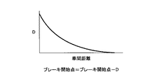
ECU10は、図3,5に示されるように、電池受け入れ可能パワーWinに基づいて減速距離を算出する(ステップ40)。図3は、図4のステップ40における減速距離の算出を説明するための図である。図5は、図4のステップ40における減速距離を算出するためのフローである。図5において、ECU10は、車速Vに現在の実車速を設定し(ステップ100)、減速距離計算用RAM値Lをクリアする(ステップ110)。次に、ECU10は、車速Vが図4のステップ30において設定された目標車速より大きいか否かを判断する(ステップ120)。現状の実車速が目標車速より大きい場合には(ステップ120;Yes)、△V/△T[m/s2]を[数2]に従って算出する(ステップ130)。
[数2]
△V/△T=Win/(M×V)
なお、△Vは1秒間で走行する距離[m/s]、△Tは制御周期[s]、Winは電池受け入れ可能パワー[W]、Mは車両重量[kg]、Vは現状の実車速[m/s]である。
As shown in FIGS. 3 and 5, the
[Equation 2]
ΔV / ΔT = Win / (M × V)
ΔV is the distance traveled in 1 second [m / s], ΔT is the control cycle [s], Win is the battery acceptable power [W], M is the vehicle weight [kg], and V is the current actual vehicle speed. [M / s].
ここで、電池受け入れ可能パワーWinの演算式について簡単に説明する。車両が減速するときに生じる減速パワーPbr[W]がすべてバッテリ28に受け入れることができれば、燃費効率の最適化に貢献する。そこで、
[数3]
Win=Pbr×(モータ効率)
として、減速パワーPbrと電池受け入れ可能パワーWinを等しいと考える。なお、以下、モータ効率は、一般に90%以上あるので、簡単化のため100%(=1)と仮定する。
Here, the calculation formula of the battery acceptable power Win will be briefly described. If the deceleration power Pbr [W] generated when the vehicle decelerates can be received by the
[Equation 3]
Win = Pbr × (motor efficiency)
Assuming that the deceleration power Pbr and the battery acceptable power Win are equal. Hereinafter, since the motor efficiency is generally 90% or more, it is assumed that it is 100% (= 1) for simplification.
一方、動く物体に働くパワーは、力×速度で表すことができるので、減速力をFbr[N]、そのときの速度をV[m/s]とすると、
[数4]
Pbr=Fbr×V
と表すことができる。また、慣性の法則に従い、車両重量M[kg]、減速加速度α[m/s2]とすると、減速力Fbrは、
[数5]
Fbr=M×α
と表すことができる。ここで、
[数6]
α=δV/δt:(Vは速度)
≒△V/△T:(△Tが小さいとき)
と考えることができるので、[数5]は、
[数7]
Fbr=M×(△V/△T)
と変形することができる。
On the other hand, since the power acting on a moving object can be expressed by force × speed, if the deceleration force is Fbr [N] and the speed at that time is V [m / s],
[Equation 4]
Pbr = Fbr × V
It can be expressed as. Further, when the vehicle weight M [kg] and the deceleration acceleration α [m / s 2 ] are obeyed according to the law of inertia, the deceleration force Fbr is
[Equation 5]
Fbr = M × α
It can be expressed as. here,
[Equation 6]
α = δV / δt: (V is speed)
≒ △ V / △ T: (when △ T is small)
[Equation 5] is
[Equation 7]
Fbr = M × (ΔV / ΔT)
And can be transformed.
さらに、路面に勾配θがあった場合の重力の影響を減速力Fbrに加味すると、重力加速度をg[m/s2]とするならば、その勾配補正項を追加して、
[数8]
Fbr=M×(△V/△T)−M×g×sinθ
=M×(△V/△T−g×sinθ)
と表すことができる。
Furthermore, if the influence of gravity when there is a gradient θ on the road surface is added to the deceleration force Fbr, if the gravitational acceleration is g [m / s 2 ], the gradient correction term is added,
[Equation 8]
Fbr = M × (ΔV / ΔT) −M × g × sinθ
= M × (ΔV / ΔT-g × sinθ)
It can be expressed as.
したがって、[数3],[数4],[数8]に基づいて、
[数9]
Win=Pbr=M×(△V/△T−g×sinθ)×V
と表すことができる。
Therefore, based on [Equation 3], [Equation 4], and [Equation 8],
[Equation 9]
Win = Pbr = M × (ΔV / ΔT−g × sin θ) × V
It can be expressed as.
図5に戻り、ECU10は、車速Vを1秒後の車速(V−△V)の演算値に更新するとともに(ステップ140)、減速距離計算用RAM値Lを(L+V+△V/2)の演算値に更新する(ステップ150)。ステップ120に戻り、あらためて、車速Vが図4のステップ30において設定された目標車速より大きいか否かを判断し、ステップ140で設定された車速Vの値が目標車速より大きい場合には(ステップ120;Yes)、同様に△V/△Tを算出し(ステップ130)、ステップ140で設定された車速Vの値が目標車速より大きくない場合には(ステップ120;No)、そのときの減速距離計算用RAM値Lを減速距離とする(ステップ160)。すなわち、図3に示されるように、図5のステップ160で算出された減速距離が、回生ブレーキのみで(電池受け入れ可能パワーWinのみで)現状車速から目標車速まで減速する場合に必要な制動距離に相当する。
Returning to FIG. 5, the
図4に戻り、ECU10は、ブレーキ開始点までの距離を算出する(ステップ50)。ブレーキ開始点までの距離は、要減速地点から減速距離を引いた距離に相当する。この際、ブレーキ開始点までの距離が負であれば、回生ブレーキのみで目標車速まで減速したとしてもブレーキ開始点を越えてしまうとして、本フローは終了する。
Returning to FIG. 4, the
ECU10は、車両の走行状況に基づいて、ブレーキ開始点までの距離の補正を行う(ステップ60)。例えば、図6に示されるようなマップと演算式に基づいて補正を行う。図6は、他車との車間距離に基づくブレーキ開始点の補正をするためのマップとその演算式である。前車との車間距離に対応する補正係数Dを図6によって規定し、ステップ50で算出されたブレーキ開始点までの距離から前車との現車間距離に対応する補正係数Dを引くことによって補正を行う。つまり、レーダーなどで前車との車間距離を監視し、所定距離以内の場合にはブレーキ開始点を手前にすることができる。
The
なお、雨の場合には要減速地点における目標車速を下げてもよいし、霧の場合には要減速地点の位置座標を手前に設定してもよい。また、路車間通信を利用し、要減速地点と自車両の間に存在する車両の数を検出し、車両数に応じてブレーキ開始点を手前にすることができる。 In the case of rain, the target vehicle speed at the required deceleration point may be lowered, and in the case of fog, the position coordinates of the required deceleration point may be set in front. Further, road-to-vehicle communication can be used to detect the number of vehicles existing between the deceleration required point and the host vehicle, and bring the brake start point to the front according to the number of vehicles.
ECU10は、ブレーキ開始点までの距離が零になった地点で、案内装置40による表示や音声によってブレーキ操作のドライバーに対する案内を開始する(ステップ70)。ドライバーはブレーキ操作の案内を開始した地点からブレーキ操作を始めるので、ドライバーのブレーキ操作量(踏力)は回生ブレーキのみの状態から大きくかけ離れることはないと考えられる。
The
ところで、一旦停止の指示のある地点、踏切、有料道路の料金所といった地点を目標とする要減速地点に設定する場合には、その地点に向かって減速することが十分予測できるが、青信号の交差点を直進する場合など、要減速地点に向かって必ずしも減速するとは限らない場合がある。そこで、そのような場合であっても、的確に車両の減速を事前に予測することができるようにするためには、例えば、右左折の予測を行えばよい。右左折する場合には、車両の減速が期待できるからである。 By the way, when setting a point such as a point where a stop is instructed, a railroad crossing, or a toll gate on a toll road as a target deceleration point, it can be predicted that the vehicle will decelerate toward that point. There is a case where the vehicle does not necessarily decelerate toward the deceleration required point, such as when going straight on. Therefore, even in such a case, in order to be able to accurately predict vehicle deceleration in advance, for example, a right / left turn may be predicted. This is because the vehicle can be expected to decelerate when making a right or left turn.
図8は、右左折の予測を説明するための図である。図8において、車両は右折レーン53を走行していることを示している。ECU10は、要減速地点Pgとして、停止線60をナビゲーション装置7から取得する。ECU10やナビゲーション装置7は、右折レーン若しくは左折レーンを走行している場合やナビゲーション装置7の経路案内機能で右折又は左折の指示をしている場合やウィンカ信号を受信した場合に、その方向に右左折すると予測することができる。右折レーン若しくは左折レーンを走行している場合を判断するためには、例えば、カメラで走行レーンを認識したり、車両を捕捉可能な路側装置との関係において車両の位置を特定したり、高精度GPS装置において車両位置を特定したりすればよい。右左折の予測が検知されれば、ナビゲーション装置7が抽出した要減速地点のうち現在の車両位置との関係において進行方向にある直近の要減速地点を、要減速地点Pgとして特定する。これにより、上述の図4のフローに従って、同様の制御動作を行うことができるようになる。
FIG. 8 is a diagram for explaining prediction of a right / left turn. FIG. 8 shows that the vehicle is traveling on the
したがって、上述の実施例によれば、減速が行われる場合には、燃費向上に寄与する回生ブレーキが作動するようにドライバーのブレーキ操作を誘導することができる。 Therefore, according to the above-described embodiment, when deceleration is performed, the brake operation of the driver can be guided so that the regenerative brake that contributes to the improvement of fuel consumption is activated.
以上、本発明の好ましい実施例について詳説したが、本発明は、上述した実施例に制限されることはなく、本発明の範囲を逸脱することなく、上述した実施例に種々の変形及び置換を加えることができる。 The preferred embodiments of the present invention have been described in detail above. However, the present invention is not limited to the above-described embodiments, and various modifications and substitutions can be made to the above-described embodiments without departing from the scope of the present invention. Can be added.
例えば、上述の減速距離の算出において、ECU10のメモリ11の容量やCPUの演算能力が低い場合には、現車速や目標車速などに基づき既定のマップに従って減速距離を算出してもよい。
For example, in the above calculation of the deceleration distance, when the capacity of the memory 11 of the
また、ブレーキ開始地点に車両が到達してからブレーキ操作の開始を案内するのではなく、ECU10はブレーキ開始地点に車両が到達する前にブレーキ開始点を案内してもよい。例えば、「あと3秒でブレーキ操作を開始して下さい」と音声案内したり、「ブレーキ操作開始まであと○○秒」と○○部分をカウントダウン表示したりすることで、ブレーキ開始点をブレーキ開始地点に車両が到達する前に案内することができる。ブレーキ開始地点までの距離は上述のように算出可能なため、車速との関係から、ブレーキ操作地点に到達するまでの時間は容易に算出可能である。
Further, instead of guiding the start of the brake operation after the vehicle reaches the brake start point, the
6 他の車両用ECU
7 ナビゲーション装置
10 ECU
11 メモリ
20 エンジン
22 動力分割機構
24 ジェネレータ
26 インバータ
28 バッテリ
30 モータ
32 ディファレンシャル
40 案内装置
6 ECU for other vehicles
7
DESCRIPTION OF SYMBOLS 11
Claims (7)
要減速地点の地図情報を記憶する記憶手段と、
前記位置検出手段により検出された車両位置に基づき進行方向に位置する要減速地点の地図情報を前記記憶手段から抽出する抽出手段と、
前記抽出手段によって抽出された要減速地点の地図情報に基づいて、その要減速地点における目標車速を設定する目標車速設定手段と、
現在車速から前記目標車速設定手段によって設定された目標車速まで回生ブレーキで減速する場合に必要な減速距離を算出する減速距離算出手段と、
前記抽出手段によって地図情報が抽出された要減速地点と前記減速距離算出手段によって算出された減速距離とに基づいて、ブレーキ操作の開始が必要なブレーキ開始点を、該ブレーキ開始点に前記車両が到達する前に案内する案内手段を備える、車両用運転支援装置。 Position detecting means for detecting the position of the vehicle;
Storage means for storing map information of the deceleration point required;
Extracting means for extracting from the storage means the map information of the decelerating points required in the traveling direction based on the vehicle position detected by the position detecting means;
Target vehicle speed setting means for setting a target vehicle speed at the required deceleration point based on the map information of the required deceleration point extracted by the extraction means;
A deceleration distance calculating means for calculating a deceleration distance required when decelerating with a regenerative brake from a current vehicle speed to a target vehicle speed set by the target vehicle speed setting means;
Based on the required deceleration point from which the map information has been extracted by the extraction means and the deceleration distance calculated by the deceleration distance calculation means, the vehicle has a brake start point that requires the start of a brake operation as the brake start point. A vehicle driving support apparatus comprising guidance means for guiding before reaching the vehicle.
Priority Applications (1)
| Application Number | Priority Date | Filing Date | Title |
|---|---|---|---|
| JP2006038098A JP4702086B2 (en) | 2006-02-15 | 2006-02-15 | Vehicle driving support device |
Applications Claiming Priority (1)
| Application Number | Priority Date | Filing Date | Title |
|---|---|---|---|
| JP2006038098A JP4702086B2 (en) | 2006-02-15 | 2006-02-15 | Vehicle driving support device |
Publications (2)
| Publication Number | Publication Date |
|---|---|
| JP2007221889A JP2007221889A (en) | 2007-08-30 |
| JP4702086B2 true JP4702086B2 (en) | 2011-06-15 |
Family
ID=38498529
Family Applications (1)
| Application Number | Title | Priority Date | Filing Date |
|---|---|---|---|
| JP2006038098A Expired - Fee Related JP4702086B2 (en) | 2006-02-15 | 2006-02-15 | Vehicle driving support device |
Country Status (1)
| Country | Link |
|---|---|
| JP (1) | JP4702086B2 (en) |
Cited By (6)
| Publication number | Priority date | Publication date | Assignee | Title |
|---|---|---|---|---|
| EP3828048A1 (en) | 2019-11-12 | 2021-06-02 | Toyota Jidosha Kabushiki Kaisha | Travel control device, travel control method, and non-transitory storage medium |
| EP3835156A1 (en) | 2019-12-11 | 2021-06-16 | Toyota Jidosha Kabushiki Kaisha | Travel control device, travel control method, non-transitory storage medium, and vehicle |
| DE102021125957A1 (en) | 2020-10-23 | 2022-04-28 | Toyota Jidosha Kabushiki Kaisha | PROPULSION CONTROL DEVICE, METHOD AND NON-TRANSITORY STORAGE MEDIA |
| DE102021129708A1 (en) | 2020-11-17 | 2022-05-19 | Toyota Jidosha Kabushiki Kaisha | Driving control device, driving control method and non-volatile storage medium |
| DE102022106658A1 (en) | 2021-03-26 | 2022-09-29 | Toyota Jidosha Kabushiki Kaisha | PROPULSION CONTROL DEVICE, PROPULSION CONTROL METHOD AND NON-TRANSITORY STORAGE MEDIA |
| EP3576976B1 (en) * | 2017-02-03 | 2024-01-24 | Bentley Motors Limited | Regenerative braking system |
Families Citing this family (32)
| Publication number | Priority date | Publication date | Assignee | Title |
|---|---|---|---|---|
| SE531922C2 (en) * | 2008-01-28 | 2009-09-08 | Scania Cv Abp | Method, system and computer program for automatic has the speed control of a motor vehicle |
| JP4985440B2 (en) * | 2008-02-01 | 2012-07-25 | 株式会社デンソー | Regenerative braking status notification device |
| JP4914868B2 (en) * | 2008-04-22 | 2012-04-11 | 本田技研工業株式会社 | Control device for electric vehicle |
| JP5262692B2 (en) * | 2008-12-25 | 2013-08-14 | 日産自動車株式会社 | Vehicle brake operation evaluation device, vehicle brake operation evaluation method, brake control device, and battery control device |
| US8190325B2 (en) * | 2009-02-19 | 2012-05-29 | Ford Global Technologies, Llc | System and method for displaying an instantaneous fuel economy of a vehicle |
| JP4807421B2 (en) | 2009-03-04 | 2011-11-02 | 株式会社デンソー | In-vehicle alarm system |
| JP2011024353A (en) | 2009-07-16 | 2011-02-03 | Aisin Aw Co Ltd | Guidance device, guidance method, and guidance program |
| JP2011130547A (en) | 2009-12-16 | 2011-06-30 | Aisin Aw Co Ltd | Driving support device, method, and program |
| JP5521526B2 (en) | 2009-12-16 | 2014-06-18 | アイシン・エィ・ダブリュ株式会社 | Driving support apparatus, method and program |
| WO2011096068A1 (en) * | 2010-02-05 | 2011-08-11 | パイオニア株式会社 | System and method of supporting driving |
| SE535806C2 (en) * | 2010-04-12 | 2012-12-27 | Scania Cv Ab | Hybrid vehicle, and method of a hybrid vehicle |
| DE102010031540A1 (en) * | 2010-07-20 | 2012-01-26 | Robert Bosch Gmbh | Method and device for operating a vehicle, which comprises at least one electric machine |
| JP2012034501A (en) | 2010-07-30 | 2012-02-16 | Aisin Aw Co Ltd | Device, method and program for driving support |
| JP5454689B2 (en) * | 2010-08-02 | 2014-03-26 | トヨタ自動車株式会社 | Information processing apparatus for vehicle |
| JP2012117938A (en) * | 2010-12-01 | 2012-06-21 | Toyota Motor Corp | Information processor for vehicle |
| JP5360235B2 (en) * | 2010-12-02 | 2013-12-04 | トヨタ自動車株式会社 | Vehicle control device |
| EP2476596A1 (en) * | 2011-01-12 | 2012-07-18 | Harman Becker Automotive Systems GmbH | Energy efficient driving assistance |
| JP5652214B2 (en) * | 2011-01-14 | 2015-01-14 | 株式会社デンソー | Driving assistance device |
| SE535591C2 (en) | 2011-02-03 | 2012-10-09 | Scania Cv Ab | Method for determining a braking position for a regenerative braking of a vehicle, device, braking system and vehicle |
| WO2012127568A1 (en) | 2011-03-18 | 2012-09-27 | トヨタ自動車株式会社 | Drive assist apparatus, and information processing apparatus for vehicles |
| JP5700131B2 (en) | 2011-08-29 | 2015-04-15 | トヨタ自動車株式会社 | Information processing apparatus for vehicle and information processing method for vehicle |
| FR2996703B1 (en) * | 2012-10-10 | 2015-03-20 | Renault Sas | METHOD FOR RECOVERING ELECTRIC ENERGY WITH VOLTAGE SMOOTHING ON AN INBOARD ELECTRICAL NETWORK |
| US9026348B2 (en) | 2012-12-21 | 2015-05-05 | Honda Motor Co., Ltd. | System and method for brake coaching |
| JP5900448B2 (en) * | 2013-09-30 | 2016-04-06 | トヨタ自動車株式会社 | Driving assistance device |
| JP2015154602A (en) * | 2014-02-14 | 2015-08-24 | トヨタ自動車株式会社 | Driving support device and driving support method |
| JP2016001970A (en) * | 2014-06-12 | 2016-01-07 | 三菱自動車工業株式会社 | On-vehicle battery charging/discharging display device |
| JP6191570B2 (en) | 2014-09-25 | 2017-09-06 | トヨタ自動車株式会社 | Vehicle control device |
| GB2539676B (en) | 2015-06-23 | 2020-11-25 | Bentley Motors Ltd | A method of controlling speed of a vehicle |
| JP6330791B2 (en) | 2015-11-19 | 2018-05-30 | トヨタ自動車株式会社 | Vehicle control device |
| DE102016218070A1 (en) * | 2016-09-21 | 2018-05-03 | Continental Automotive Gmbh | Determination of the optimal beginning of the delay phase in the backend |
| CN112297850B (en) * | 2020-10-23 | 2021-11-30 | 东风汽车股份有限公司 | Method for weakening impact current in failure mode of motor controller |
| CN112903305B (en) * | 2020-12-31 | 2023-04-25 | 中汽院(重庆)汽车检测有限公司 | Test and evaluation method for emergency obstacle avoidance capability of automobile |
Citations (4)
| Publication number | Priority date | Publication date | Assignee | Title |
|---|---|---|---|---|
| JPH09166209A (en) * | 1995-12-15 | 1997-06-24 | Aqueous Res:Kk | Vehicle control device |
| JPH11222055A (en) * | 1998-02-10 | 1999-08-17 | Nissan Motor Co Ltd | Vehicle control device |
| JP2000052950A (en) * | 1998-08-18 | 2000-02-22 | Honda Motor Co Ltd | Traveling controller for vehicle |
| JP2005165423A (en) * | 2003-11-28 | 2005-06-23 | Denso Corp | Vehicle-driving support device |
-
2006
- 2006-02-15 JP JP2006038098A patent/JP4702086B2/en not_active Expired - Fee Related
Patent Citations (4)
| Publication number | Priority date | Publication date | Assignee | Title |
|---|---|---|---|---|
| JPH09166209A (en) * | 1995-12-15 | 1997-06-24 | Aqueous Res:Kk | Vehicle control device |
| JPH11222055A (en) * | 1998-02-10 | 1999-08-17 | Nissan Motor Co Ltd | Vehicle control device |
| JP2000052950A (en) * | 1998-08-18 | 2000-02-22 | Honda Motor Co Ltd | Traveling controller for vehicle |
| JP2005165423A (en) * | 2003-11-28 | 2005-06-23 | Denso Corp | Vehicle-driving support device |
Cited By (9)
| Publication number | Priority date | Publication date | Assignee | Title |
|---|---|---|---|---|
| EP3576976B1 (en) * | 2017-02-03 | 2024-01-24 | Bentley Motors Limited | Regenerative braking system |
| EP3828048A1 (en) | 2019-11-12 | 2021-06-02 | Toyota Jidosha Kabushiki Kaisha | Travel control device, travel control method, and non-transitory storage medium |
| EP3835156A1 (en) | 2019-12-11 | 2021-06-16 | Toyota Jidosha Kabushiki Kaisha | Travel control device, travel control method, non-transitory storage medium, and vehicle |
| US11807214B2 (en) | 2019-12-11 | 2023-11-07 | Toyota Jidosha Kabushiki Kaisha | Travel control device, travel control method, non-transitory storage medium, and vehicle for deciding a power source for traveling based on a predicted amount of regenerative energy and thermal information |
| DE102021125957A1 (en) | 2020-10-23 | 2022-04-28 | Toyota Jidosha Kabushiki Kaisha | PROPULSION CONTROL DEVICE, METHOD AND NON-TRANSITORY STORAGE MEDIA |
| US11820354B2 (en) | 2020-10-23 | 2023-11-21 | Toyota Jidosha Kabushiki Kaisha | Driving control device, method, and non-transitory storage medium |
| DE102021129708A1 (en) | 2020-11-17 | 2022-05-19 | Toyota Jidosha Kabushiki Kaisha | Driving control device, driving control method and non-volatile storage medium |
| US11780441B2 (en) | 2020-11-17 | 2023-10-10 | Toyota Jidosha Kabushiki Kaisha | Traveling control apparatus, traveling control method, and non-transitory storage medium |
| DE102022106658A1 (en) | 2021-03-26 | 2022-09-29 | Toyota Jidosha Kabushiki Kaisha | PROPULSION CONTROL DEVICE, PROPULSION CONTROL METHOD AND NON-TRANSITORY STORAGE MEDIA |
Also Published As
| Publication number | Publication date |
|---|---|
| JP2007221889A (en) | 2007-08-30 |
Similar Documents
| Publication | Publication Date | Title |
|---|---|---|
| JP4702086B2 (en) | Vehicle driving support device | |
| CN107340769B (en) | Vehicle control system, vehicle control method, and recording medium of program thereof | |
| JP6293197B2 (en) | Vehicle control system, vehicle control method, and vehicle control program | |
| US9994234B2 (en) | Driving assistance apparatus | |
| JP5429197B2 (en) | Vehicle control device | |
| JP5846214B2 (en) | Driving assistance device | |
| US9437110B2 (en) | Drive assisting apparatus | |
| CN109383505B (en) | System and method for determining efficient driving speed of vehicle | |
| US20170015328A1 (en) | Drive assist apparatus and method | |
| US11254313B2 (en) | Travelling control apparatus | |
| JP5071018B2 (en) | Vehicle consumption energy estimation device, vehicle consumption energy estimation method, and computer program | |
| US20210188264A1 (en) | Vehicle control device | |
| JP2011063186A (en) | Vehicle drive controller | |
| JP7059652B2 (en) | Vehicle control system | |
| JP2010132241A (en) | Traveling support device, traveling support method, and computer program | |
| JP7234562B2 (en) | CONTROL METHOD AND CONTROL DEVICE FOR HYBRID VEHICLE | |
| JP5835126B2 (en) | Driving assistance device | |
| US11801868B2 (en) | Hybrid vehicle, control method therefor, and storage medium | |
| JP2009012495A (en) | Driving force controller for vehicle | |
| JP2007168743A (en) | Driving controller for hybrid car | |
| JP6040792B2 (en) | Travel control device | |
| US20230036756A1 (en) | Travel support control device for hybrid vehicle | |
| KR20190073248A (en) | Method for controlling driving of environmentally friendly vehicle using front driving environment information |
Legal Events
| Date | Code | Title | Description |
|---|---|---|---|
| A621 | Written request for application examination |
Free format text: JAPANESE INTERMEDIATE CODE: A621 Effective date: 20090121 |
|
| A977 | Report on retrieval |
Free format text: JAPANESE INTERMEDIATE CODE: A971007 Effective date: 20101122 |
|
| A131 | Notification of reasons for refusal |
Free format text: JAPANESE INTERMEDIATE CODE: A131 Effective date: 20101130 |
|
| A521 | Written amendment |
Free format text: JAPANESE INTERMEDIATE CODE: A523 Effective date: 20110121 |
|
| TRDD | Decision of grant or rejection written | ||
| A01 | Written decision to grant a patent or to grant a registration (utility model) |
Free format text: JAPANESE INTERMEDIATE CODE: A01 Effective date: 20110208 |
|
| A61 | First payment of annual fees (during grant procedure) |
Free format text: JAPANESE INTERMEDIATE CODE: A61 Effective date: 20110221 |
|
| R151 | Written notification of patent or utility model registration |
Ref document number: 4702086 Country of ref document: JP Free format text: JAPANESE INTERMEDIATE CODE: R151 |
|
| LAPS | Cancellation because of no payment of annual fees |