JP6018169B2 - Storage device failure determination method - Google Patents

Storage device failure determination method Download PDF

Info

Publication number
JP6018169B2
JP6018169B2 JP2014261157A JP2014261157A JP6018169B2 JP 6018169 B2 JP6018169 B2 JP 6018169B2 JP 2014261157 A JP2014261157 A JP 2014261157A JP 2014261157 A JP2014261157 A JP 2014261157A JP 6018169 B2 JP6018169 B2 JP 6018169B2
Authority
JP
Japan
Prior art keywords
cell
power storage
voltage
storage module
cells
Prior art date
Legal status (The legal status is an assumption and is not a legal conclusion. Google has not performed a legal analysis and makes no representation as to the accuracy of the status listed.)
Expired - Fee Related
Application number
JP2014261157A
Other languages
Japanese (ja)
Other versions
JP2016122542A (en
Inventor
室 岳志
岳志 室
直樹 丸野
直樹 丸野
訓 小茂田
訓 小茂田
康弘 松本
康弘 松本
Current Assignee (The listed assignees may be inaccurate. Google has not performed a legal analysis and makes no representation or warranty as to the accuracy of the list.)
Honda Motor Co Ltd
Original Assignee
Honda Motor Co Ltd
Priority date (The priority date is an assumption and is not a legal conclusion. Google has not performed a legal analysis and makes no representation as to the accuracy of the date listed.)
Filing date
Publication date
Application filed by Honda Motor Co Ltd filed Critical Honda Motor Co Ltd
Priority to JP2014261157A priority Critical patent/JP6018169B2/en
Publication of JP2016122542A publication Critical patent/JP2016122542A/en
Application granted granted Critical
Publication of JP6018169B2 publication Critical patent/JP6018169B2/en
Expired - Fee Related legal-status Critical Current
Anticipated expiration legal-status Critical

Links

Images

Classifications

    • YGENERAL TAGGING OF NEW TECHNOLOGICAL DEVELOPMENTS; GENERAL TAGGING OF CROSS-SECTIONAL TECHNOLOGIES SPANNING OVER SEVERAL SECTIONS OF THE IPC; TECHNICAL SUBJECTS COVERED BY FORMER USPC CROSS-REFERENCE ART COLLECTIONS [XRACs] AND DIGESTS
    • Y02TECHNOLOGIES OR APPLICATIONS FOR MITIGATION OR ADAPTATION AGAINST CLIMATE CHANGE
    • Y02EREDUCTION OF GREENHOUSE GAS [GHG] EMISSIONS, RELATED TO ENERGY GENERATION, TRANSMISSION OR DISTRIBUTION
    • Y02E60/00Enabling technologies; Technologies with a potential or indirect contribution to GHG emissions mitigation
    • Y02E60/10Energy storage using batteries

Landscapes

  • Tests Of Electric Status Of Batteries (AREA)
  • Charge And Discharge Circuits For Batteries Or The Like (AREA)
  • Secondary Cells (AREA)

Description

本発明は複数のセルを有する蓄電モジュールを複数備える蓄電装置の故障判定方法に関する。   The present invention relates to a failure determination method for a power storage device including a plurality of power storage modules having a plurality of cells.

電気自動車やハイブリッド車の動力源として、大型のリチウムイオン2次電池が用いられている。単電池(以下、セルという)が電気的に複数接続されて蓄電モジュールが構成され、複数の蓄電モジュールが電気的に複数接続されることにより、リチウムイオン2次電池を有する組電池が構成される。組電池は、電気自動車やハイブリッド車の動力源として必要な電気を出力する。   A large-sized lithium ion secondary battery is used as a power source for electric vehicles and hybrid vehicles. A plurality of single cells (hereinafter referred to as cells) are electrically connected to form a power storage module, and a plurality of power storage modules are electrically connected to form a battery pack having a lithium ion secondary battery. . The assembled battery outputs electricity necessary as a power source for electric vehicles and hybrid vehicles.

組電池において、一部のセルの電圧が所定の値に至るまで上昇しない等、一部のセルに不具合等が生じた場合には、不具合等が生じたセルを含む蓄電モジュールが、新品の正常な蓄電モジュール(以下、「新品モジュール」という)と交換される。また、組電池の寿命が尽きた場合には、寿命が尽きた組電池が、新品の正常な組電池と交換される。不具合等が生じたセルを含む蓄電モジュールが新品モジュールと交換される際には、新品モジュールの電圧を、組電池において交換されなかった蓄電モジュール(以下、「再利用モジュール」という)の電圧に揃えられることが知られている(特許文献1参照)。   In the assembled battery, if a malfunction occurs in some cells, such as the voltage of some cells does not rise to a predetermined value, the storage module including the malfunctioned cell is It is exchanged for a new power storage module (hereinafter referred to as “new module”). In addition, when the battery life has expired, the battery pack whose life has expired is replaced with a new normal battery pack. When a storage module including a defective cell is replaced with a new module, the voltage of the new module is set to the voltage of the storage module that has not been replaced in the assembled battery (hereinafter referred to as “reuse module”). It is known (see Patent Document 1).

特許第3750318号公報Japanese Patent No. 3750318

しかし、再利用モジュールは、容量が小さく、抵抗値が高い。このため、組電池の充電を行うと、新品モジュールにおいては電圧上昇が小さく、容量が小さい再利用モジュールにおいては電圧上昇が大きい。この結果、組電圧内のセルにおける電圧の偏差が規定電圧を超えてしまい、新品モジュールが、不具合の生じたセルを含む蓄電モジュールとして判定される(故障と判定される)ことがある。   However, the reuse module has a small capacity and a high resistance value. For this reason, when the assembled battery is charged, the voltage rise is small in the new module, and the voltage rise is large in the reuse module having a small capacity. As a result, the voltage deviation in the cell within the assembled voltage exceeds the specified voltage, and the new module may be determined as a power storage module including a defective cell (determined as a failure).

本発明は、不具合が生じたセルを含む蓄電モジュールが交換された後に、新品モジュールが、不具合の生じたセルを含む蓄電モジュールとして判定されることを回避できる蓄電装置の故障判定方法を提供することを目的とする。   The present invention provides a failure determination method for a storage device that can prevent a new module from being determined as a storage module including a defective cell after the storage module including the defective cell is replaced. With the goal.

上記目的を達成するため本発明は、複数のセル(例えば、後述のセル112)を有する蓄電モジュール(例えば、後述の蓄電モジュール111)を複数備えて構成される組電池(例えば、後述のバッテリパック11)を有する蓄電装置における、全ての前記セル(例えば、後述のセル112)の電圧を検出し、検出した前記電圧と第1閾値とを比較することにより前記セル(例えば、後述のセル112)が正常か否かの前記セル(例えば、後述のセル112)の故障判定を行う工程と、前記セル(例えば、後述のセル112)の故障判定により故障と判定された前記セル(例えば、後述のセル112)を有する前記蓄電モジュール(例えば、後述の蓄電モジュール111)を、正常な前記セル(例えば、後述のセル112)を有する前記蓄電モジュール(例えば、後述の蓄電モジュール111)であって故障と判断されていない前記蓄電モジュール(例えば、後述の蓄電モジュール111)よりも満充電容量が大きい前記蓄電モジュール(例えば、後述の蓄電モジュール111)に交換する蓄電モジュール交換を行った後には、各前記蓄電モジュール(例えば、後述の蓄電モジュール111)毎に、各前記蓄電モジュール(例えば、後述の蓄電モジュール111)における前記セル(例えば、後述のセル112)の電圧を検出し、検出した前記電圧と第2閾値とを比較することにより、各前記蓄電モジュール(例えば、後述の蓄電モジュール111)毎に前記セル(例えば、後述のセル112)が正常か否かの前記組電池(例えば、後述のバッテリパック11)の故障判定を行う工程と、を有する蓄電装置の故障判定方法を提供する。   In order to achieve the above object, the present invention provides an assembled battery (for example, a battery pack described later) including a plurality of power storage modules (for example, power storage modules 111 described later) having a plurality of cells (for example, cells 112 described later). 11), the voltage of all the cells (for example, a cell 112 described later) is detected, and the detected voltage is compared with the first threshold value to compare the detected cell with the first threshold (for example, the cell 112 described later). A step of performing a failure determination of the cell (for example, a cell 112 described later) whether or not is normal, and the cell (for example, a later described cell) determined to be a failure by the failure determination of the cell (for example, a cell 112 described later) The power storage module (for example, a power storage module 111 described later) having the cell 112) is replaced with the power storage module having the normal cell (for example, cell 112 described later). The power storage module (for example, a power storage module 111 to be described later) having a larger full charge capacity than the power storage module (for example, the power storage module 111 to be described later) that is a module (for example, a power storage module 111 to be described later) that is not determined to be a failure. After replacement of the storage module to be replaced, the cell (for example, a cell to be described later) in each storage module (for example, storage module 111 to be described later) for each storage module (for example storage module 111 to be described later). 112), and by comparing the detected voltage with a second threshold, the cell (for example, cell 112 described later) is normal for each power storage module (for example, power storage module 111 described later). Whether or not the assembled battery (for example, a battery pack 11 to be described later) is determined to be faulty When, it provides a failure determination method of a power storage device having a.

本発明によれば、複数の蓄電モジュールのうちの故障と判定された蓄電モジュールを新品の正常の蓄電モジュールに交換した後には、蓄電装置を構成する組電池における全てのセルの電圧と、一の値を有する第1閾値とを比較することにより故障判定を行わない。このため、電圧の上昇・下降スピードが遅い新品の蓄電モジュールのセルが、故障と判定されることを防止できる。この結果、蓄電モジュール交換後に、不要な誤った故障との判定がなされることを防止できる。   According to the present invention, after replacing a power storage module determined to be a failure among a plurality of power storage modules with a new normal power storage module, the voltages of all cells in the assembled battery constituting the power storage device are Failure determination is not performed by comparing with a first threshold having a value. For this reason, it can prevent that the cell of the new electrical storage module with a slow voltage rising / lowering speed is determined to be a failure. As a result, it is possible to prevent the determination of an unnecessary erroneous failure after the storage module replacement.

また、前記蓄電モジュール交換の後には、全ての前記セル(例えば、後述のセル112)のうちの最小の充電可能容量と最小の放電可能容量とから得られる前記蓄電装置の使用可能容量と第3閾値とを比較することにより前記組電池(例えば、後述のバッテリパック11)の故障判定を行う工程を有することが好ましい。   In addition, after the storage module replacement, the usable capacity of the power storage device obtained from the minimum chargeable capacity and the minimum dischargeable capacity of all the cells (for example, a cell 112 described later) and the third capacity It is preferable to include a step of performing a failure determination of the assembled battery (for example, a battery pack 11 described later) by comparing with a threshold value.

この発明によれば、前記蓄電装置を構成する組電池の使用可能容量と第3閾値とを比較することにより、蓄電装置の使用可能容量が低下して、蓄電装置の組電池の交換が必要になったときに、蓄電装置の使用可能容量が低下したことを、容易に検出することができる。   According to this invention, by comparing the usable capacity of the assembled battery constituting the power storage device with the third threshold value, the usable capacity of the power storage device is reduced, and the assembled battery of the power storage device needs to be replaced. When this happens, it can be easily detected that the usable capacity of the power storage device has decreased.

また、前記蓄電モジュール交換の後には、全ての前記セル(例えば、後述のセル112)の電圧のうちの最高電圧値と最低電圧値との差が第4閾値以上である場合に前記組電池(例えば、後述のバッテリパック11)の故障判定を行う工程を有することが好ましい。   In addition, after the storage module replacement, when the difference between the highest voltage value and the lowest voltage value among the voltages of all the cells (for example, a cell 112 described later) is equal to or greater than a fourth threshold value, the assembled battery ( For example, it is preferable to include a step of determining a failure of the battery pack 11) described later.

この発明によれば、全ての前記セルのうちの最小の充電可能容量と最小の放電可能容量とから得られる前記蓄電装置の使用可能容量を算出せずに、組電池の故障判定を行うことができる。即ち、各セルにおけるSOCを算出したり、各セルにおけるSOCに基づいて各セルの容量を算出したりせずに、組電池の故障判定を行うことができる。このため、組電池の故障判定を行うための処理を容易とすることができる。   According to the present invention, it is possible to determine the failure of the assembled battery without calculating the usable capacity of the power storage device obtained from the minimum chargeable capacity and the minimum dischargeable capacity of all the cells. it can. That is, it is possible to determine the failure of the assembled battery without calculating the SOC in each cell or calculating the capacity of each cell based on the SOC in each cell. For this reason, the process for performing failure determination of an assembled battery can be made easy.

本発明によれば、不具合が生じたセルを含む蓄電モジュールが交換された後に、新品モジュールが、不具合の生じたセルを含む蓄電モジュールとして判定されることを回避できる蓄電装置の故障判定方法を提供することができる。   According to the present invention, there is provided a fault determination method for a power storage device that can prevent a new module from being determined as a power storage module including a defective cell after the storage module including the defective cell is replaced. can do.

本発明の第1実施形態による蓄電装置の故障判定方法が実施される車両1を示すブロック図である。1 is a block diagram showing a vehicle 1 in which a method for determining a failure of a power storage device according to a first embodiment of the present invention is implemented. 本発明の第1実施形態による蓄電装置の故障判定方法における、蓄電モジュール111の交換前のセル112の故障判定のための工程を示すフローチャートである。4 is a flowchart showing a process for determining a failure of a cell 112 before replacement of the storage module 111 in the storage device failure determination method according to the first embodiment of the present invention. 本発明の第1実施形態による蓄電装置の故障判定方法における、蓄電モジュール111の交換の後のバッテリパック11の故障判定のための工程を示すフローチャートである。3 is a flowchart showing steps for determining a failure of the battery pack 11 after replacement of the storage module 111 in the storage device failure determination method according to the first embodiment of the present invention. 本発明の第2実施形態による蓄電装置の故障判定方法が実施される車両1Aを示すブロック図である。It is a block diagram which shows vehicle 1A with which the failure determination method of the electrical storage apparatus by 2nd Embodiment of this invention is implemented. 本発明の第2実施形態による蓄電装置の故障判定方法における、蓄電モジュール111の交換前のセル112の故障判定のための工程を示すフローチャートである。7 is a flowchart showing a process for determining a failure of a cell 112 before replacement of a storage module 111 in a storage apparatus failure determination method according to a second embodiment of the present invention. 本発明の第2実施形態による蓄電装置の故障判定方法における、蓄電モジュール111の交換の後のバッテリパック11の故障判定のための工程を示すフローチャートである。6 is a flowchart illustrating a process for determining a failure of a battery pack 11 after replacement of a storage module 111 in a storage device failure determination method according to a second embodiment of the present invention.

<第1実施形態>
以下、本発明の第1実施形態について、図面を参照して詳しく説明する。なお、第2実施形態以降の説明において、第1実施形態と共通する構成については、第1実施形態と同一の符号を付し、その説明を省略する。
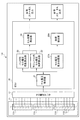
図1は、本発明の第1実施形態による蓄電装置の故障判定方法が実施される車両1を示すブロック図である。図2は、本発明の第1実施形態による蓄電装置の故障判定方法における、蓄電モジュール111の交換前のセル112の故障判定のための工程を示すフローチャートである。図3は、本発明の第1実施形態による蓄電装置の故障判定方法における、蓄電モジュール111の交換の後のバッテリパック11の故障判定のための工程を示すフローチャートである。
<First Embodiment>
Hereinafter, a first embodiment of the present invention will be described in detail with reference to the drawings. Note that in the description of the second and subsequent embodiments, the same reference numerals as those in the first embodiment are assigned to configurations common to the first embodiment, and the description thereof is omitted.
FIG. 1 is a block diagram showing a vehicle 1 in which a failure determination method for a power storage device according to a first embodiment of the present invention is implemented. FIG. 2 is a flowchart showing steps for determining a failure of the cell 112 before the replacement of the storage module 111 in the storage device failure determination method according to the first embodiment of the present invention. FIG. 3 is a flowchart showing steps for determining the failure of the battery pack 11 after the replacement of the storage module 111 in the storage device failure determination method according to the first embodiment of the present invention.

第1実施形態に係る蓄電装置の故障判定方法は、電気自動車やハイブリッド車等の、蓄電装置を構成するバッテリパック11から供給される電気により駆動する車両1において実施される。図1に示すように、車両1に設けられる蓄電装置は、組電池により構成されるバッテリパック11を有している。バッテリパック11は、複数個の蓄電モジュール111を有している。蓄電モジュール111は、例えばリチウムイオンバッテリにより構成された2次電池である複数個のセル112を有している。複数個のセル112は、積層され電気的に直列に接続されている。バッテリパック11は、高電圧バッテリを構成し、電気自動車やハイブリッド車の蓄電池として使用される。   The failure determination method for a power storage device according to the first embodiment is implemented in a vehicle 1 that is driven by electricity supplied from a battery pack 11 constituting the power storage device, such as an electric vehicle or a hybrid vehicle. As shown in FIG. 1, the power storage device provided in the vehicle 1 has a battery pack 11 formed of an assembled battery. The battery pack 11 has a plurality of power storage modules 111. The power storage module 111 includes a plurality of cells 112 that are secondary batteries configured by, for example, a lithium ion battery. The plurality of cells 112 are stacked and electrically connected in series. The battery pack 11 constitutes a high voltage battery and is used as a storage battery for an electric vehicle or a hybrid vehicle.

全てのセル112には、セル電圧センサ12が電気的に接続されている。セル電圧センサ12は、バッテリパック11における全てのセル112の無負荷電圧を検出する。また、バッテリパック11から出力される電流を検出可能な電流センサ(図示せず)が設けられている。セル電圧センサ12、電流センサ(図示せず)は、導線や基板上の配線等を介して、ECU20に電気的に接続されている。   The cell voltage sensor 12 is electrically connected to all the cells 112. The cell voltage sensor 12 detects no-load voltage of all the cells 112 in the battery pack 11. In addition, a current sensor (not shown) capable of detecting the current output from the battery pack 11 is provided. The cell voltage sensor 12 and the current sensor (not shown) are electrically connected to the ECU 20 via a conductive wire, a wiring on the substrate, or the like.

ECU20は、セル電圧センサ12からの入力信号波形を入力する入力回路や、中央演算処理ユニット(以下「CPU」という)や、CPUで実行される各種演算プログラム、各種マップ、後述の第1閾値〜第4閾値などを記憶する記憶回路や、制御信号を出力する出力回路等を備えている。これらにより、ECU20においては、セル電圧取得部21と、パック内セル電圧偏差算出部22と、モジュール内セル電圧偏差算出部23と、セル故障検出部24と、セルSOC算出部25と、セル使用可能容量算出部26と、パック使用可能容量算出部27と、故障検出部28と、が構成される。   The ECU 20 includes an input circuit for inputting an input signal waveform from the cell voltage sensor 12, a central processing unit (hereinafter referred to as "CPU"), various arithmetic programs executed by the CPU, various maps, and a first threshold value described later. A storage circuit that stores a fourth threshold value, an output circuit that outputs a control signal, and the like are provided. Thus, in the ECU 20, the cell voltage acquisition unit 21, the in-pack cell voltage deviation calculation unit 22, the in-module cell voltage deviation calculation unit 23, the cell failure detection unit 24, the cell SOC calculation unit 25, and the cell use A possible capacity calculation unit 26, a pack usable capacity calculation unit 27, and a failure detection unit 28 are configured.

セル電圧取得部21は、セル電圧センサ12により検出された全てのセル112の無負荷電圧を入力する。また、セル電圧取得部21は、セル電圧センサ12により検出された全てのセル112の無負荷電圧のデータを、パック内セル電圧偏差算出部22、モジュール内セル電圧偏差算出部23、及び、セルSOC算出部25へ出力する。   The cell voltage acquisition unit 21 inputs the no-load voltage of all the cells 112 detected by the cell voltage sensor 12. In addition, the cell voltage acquisition unit 21 converts the no-load voltage data of all the cells 112 detected by the cell voltage sensor 12 into the in-pack cell voltage deviation calculation unit 22, the in-module cell voltage deviation calculation unit 23, and the cell Output to the SOC calculation unit 25.

パック内セル電圧偏差算出部22は、セル電圧取得部21から出力された全てのセル112の無負荷電圧から、セル112の無負荷電圧の平均電圧を算出する。また、算出された平均電圧を基準としたバッテリパック11内のセル112の無負荷電圧の偏差の許容範囲、即ち、第1閾値としての、セル112の無負荷電圧の許容上限値及び許容下限値を算出し、セル故障検出部24へ出力する。   The in-pack cell voltage deviation calculation unit 22 calculates an average voltage of the no-load voltages of the cells 112 from the no-load voltages of all the cells 112 output from the cell voltage acquisition unit 21. In addition, the allowable range of deviation of the no-load voltage of the cell 112 in the battery pack 11 based on the calculated average voltage, that is, the allowable upper limit value and the allowable lower limit value of the no-load voltage of the cell 112 as the first threshold value. Is output to the cell failure detection unit 24.

モジュール内セル電圧偏差算出部23は、セル電圧取得部21により取得された、全てのセル112の無負荷電圧から、蓄電モジュール111毎に平均電圧をそれぞれ算出する。また、算出された蓄電モジュール111毎の平均電圧を基準とした各モジュール内のセル112の無負荷電圧の偏差の許容範囲、即ち、第2閾値としての、セル112の無負荷電圧の許容上限値及び許容下限値を、モジュール毎に算出し、セル故障検出部24へ出力する。   The in-module cell voltage deviation calculation unit 23 calculates an average voltage for each power storage module 111 from the no-load voltages of all the cells 112 acquired by the cell voltage acquisition unit 21. Further, an allowable range of deviation of the no-load voltage of the cell 112 in each module based on the calculated average voltage for each power storage module 111, that is, an allowable upper limit value of the no-load voltage of the cell 112 as the second threshold value The allowable lower limit value is calculated for each module and output to the cell failure detection unit 24.

セル故障検出部24は、セル電圧取得部21から出力されたセル112の無負荷電圧と、第1閾値としての、セル112の無負荷電圧の許容上限値及び許容下限値、又は、第2閾値としての、セル112の無負荷電圧の許容上限値及び許容下限値と、を比較する。これにより、セル112の無負荷電圧が第1閾値又は第2閾値を超えたか否かを判断する。後述の蓄電モジュール111の交換の前に、セル112の無負荷電圧が、第1閾値としてのセル112の無負荷電圧の許容上限値と許容下限値との間の範囲から外れたとの判断を、セル故障検出部24がした場合には、セル故障検出部24は、第1閾値を超えたセル112を有する蓄電モジュール111の交換を促す故障ステータスを、車両1に設けられた警報装置等へ出力する。また、後述の蓄電モジュール111の交換の後に、セル112の無負荷電圧が、第2閾値としてのセル112の無負荷電圧の許容上限値と許容下限値との間の範囲から外れたとの判断を、セル故障検出部24がした場合には、セル故障検出部24は、バッテリパック11の交換を促す故障ステータスを、車両1に設けられた警報装置等へ出力する。   The cell failure detection unit 24 outputs the no-load voltage of the cell 112 output from the cell voltage acquisition unit 21, the allowable upper limit value and the allowable lower limit value of the no-load voltage of the cell 112 as the first threshold value, or the second threshold value. The allowable upper limit value and the allowable lower limit value of the no-load voltage of the cell 112 are compared. Thereby, it is determined whether or not the no-load voltage of the cell 112 exceeds the first threshold value or the second threshold value. Before replacement of the power storage module 111 described later, the determination that the no-load voltage of the cell 112 is out of the range between the allowable upper limit value and the allowable lower limit value of the no-load voltage of the cell 112 as the first threshold value, When the cell failure detection unit 24 performs, the cell failure detection unit 24 outputs a failure status that prompts replacement of the power storage module 111 having the cell 112 exceeding the first threshold to an alarm device or the like provided in the vehicle 1. To do. In addition, after replacement of the power storage module 111 described later, it is determined that the no-load voltage of the cell 112 is out of the range between the allowable upper limit value and the allowable lower limit value of the no-load voltage of the cell 112 as the second threshold value. When the cell failure detection unit 24 does, the cell failure detection unit 24 outputs a failure status that prompts replacement of the battery pack 11 to an alarm device or the like provided in the vehicle 1.

セルSOC算出部25は、セル電圧取得部21によって得られた全てのセル112の電圧値と、セル112のSOC(State of Charge)特性グラフと、に基づいて、全てのセル112のSOCを算出し、セル使用可能容量算出部26へ出力する。   The cell SOC calculation unit 25 calculates the SOCs of all the cells 112 based on the voltage values of all the cells 112 obtained by the cell voltage acquisition unit 21 and the SOC (State of Charge) characteristic graph of the cells 112. And output to the cell usable capacity calculator 26.

セル使用可能容量算出部26は、セルSOC算出部25によって得られた全てのセル112の現在のSOCを用いて、
「 容量 = 放電容量の変化量(△Ah)/SOCの変化量(△SOC) 」
に基づき、各セル112の容量を算出する。また、セルSOC算出部25によって得られた各セル112の現在のSOCと、各セル112の使用下限SOCと、の差と、各セル112の容量と、の積を算出することにより、即ち、
「 放電可能容量 = 容量 × (現在のSOC − 使用下限SOC) 」
に基づき、全てのセル112について、放電可能容量を算出する。また、セル使用可能容量算出部26は、セル112の使用上限SOCと、セルSOC算出部25によって得られた全てのセル112の現在のSOCと、の差と、各セル112の容量と、の積を算出することにより、即ち、
「 充電可能容量 = 容量 × (使用上限SOC − 現在のSOC) 」
に基づき、全てのセル112について、充電可能容量を算出する。セル使用可能容量算出部26は、算出した放電可能容量、充電可能容量をパック使用可能容量算出部27へ出力する。
The cell usable capacity calculation unit 26 uses the current SOC of all the cells 112 obtained by the cell SOC calculation unit 25, and
“Capacity = Change in discharge capacity (ΔAh) / Change in SOC (ΔSOC)”
Based on the above, the capacity of each cell 112 is calculated. Further, by calculating the product of the difference between the current SOC of each cell 112 obtained by the cell SOC calculation unit 25 and the lower limit SOC of each cell 112 and the capacity of each cell 112, that is,
"Dischargeable capacity = Capacity x (Current SOC-Lower limit SOC)"
Based on the above, the dischargeable capacity is calculated for all the cells 112. Further, the cell usable capacity calculation unit 26 calculates the difference between the upper limit SOC of the cell 112 and the current SOCs of all the cells 112 obtained by the cell SOC calculation unit 25, and the capacity of each cell 112. By calculating the product, ie
"Chargeable capacity = Capacity x (Upper limit SOC-Current SOC)"
Based on the above, the chargeable capacity is calculated for all the cells 112. The cell usable capacity calculation unit 26 outputs the calculated dischargeable capacity and chargeable capacity to the pack usable capacity calculation unit 27.

パック使用可能容量算出部27は、セル使用可能容量算出部26により算出された全てのセル112の放電可能容量のうちの最小の放電可能容量と、セル使用可能容量算出部26により算出された全てのセル112の充電可能容量のうちの最小の充電可能容量と、の和を、バッテリパック11の使用可能容量として算出する。パック使用可能容量算出部27は、算出したバッテリパック11の使用可能容量を故障検出部28へ出力する。   The pack usable capacity calculation unit 27 calculates the minimum dischargeable capacity among all the dischargeable capacities of all the cells 112 calculated by the cell usable capacity calculation unit 26 and all the values calculated by the cell usable capacity calculation unit 26. The sum of the minimum chargeable capacity of the chargeable capacity of the cell 112 is calculated as the usable capacity of the battery pack 11. The pack usable capacity calculation unit 27 outputs the calculated usable capacity of the battery pack 11 to the failure detection unit 28.

故障検出部28は、パック使用可能容量算出部27により算出されたバッテリパック11の使用可能容量と、第3閾値としてのバッテリパック11の使用可能容量の下限値とを比較する。これにより、故障検出部28は、バッテリパック11の使用可能容量が第3閾値を下回ったか否かを判断する。第3閾値としては、バッテリパック11を使用可能なバッテリパックの容量の最低の値が用いられる。後述の蓄電モジュール交換の後に、バッテリパック11の使用可能容量が第3閾値を下回ったとの判断を、故障検出部28がした場合には、故障検出部28は、バッテリパック11の交換を促す故障ステータスを、車両1に設けられた警報装置等へ出力する。   The failure detection unit 28 compares the usable capacity of the battery pack 11 calculated by the pack usable capacity calculation unit 27 with the lower limit value of the usable capacity of the battery pack 11 as the third threshold value. As a result, the failure detection unit 28 determines whether or not the usable capacity of the battery pack 11 has fallen below the third threshold value. As the third threshold value, the lowest value of the capacity of the battery pack that can use the battery pack 11 is used. When the failure detection unit 28 determines that the usable capacity of the battery pack 11 has fallen below the third threshold after the storage module replacement described below, the failure detection unit 28 causes a failure to promote replacement of the battery pack 11. The status is output to an alarm device or the like provided in the vehicle 1.

上記構成を有する車両1の蓄電装置の故障判定方法については、以下のとおりである。
先ず、図2に示すように、S11では、セル電圧センサ12は、複数のセル112(図1参照)を有する蓄電モジュール111を複数備える蓄電装置のバッテリパック11における、全てのセル112の無負荷電圧を検出する。そして、セル電圧取得部21は、セル電圧センサ12により検出された全てのセル112の無負荷電圧を入力する。
The failure determination method for the power storage device of the vehicle 1 having the above configuration is as follows.
First, as shown in FIG. 2, in S11, the cell voltage sensor 12 causes the no-load of all the cells 112 in the battery pack 11 of the power storage device including a plurality of power storage modules 111 having a plurality of cells 112 (see FIG. 1). Detect voltage. And the cell voltage acquisition part 21 inputs the no-load voltage of all the cells 112 detected by the cell voltage sensor 12.

S12では、セル電圧センサ12により検出した無負荷電圧と第1閾値とを比較することによりセル112が正常か否かのセル112の故障判定を行う。具体的には、S12では、パック内セル電圧偏差算出部22は、セル電圧取得部21により取得された全てのセル112の無負荷電圧から平均電圧を算出する。次に、算出された平均電圧を基準としたバッテリパック11内のセル112の無負荷電圧の偏差の許容範囲、即ち、第1閾値としての、セル112の無負荷電圧の許容上限値及び許容下限値を算出する。そして、セル故障検出部24は、セル電圧取得部21によって取得された全てのセル112の無負荷電圧と、第1閾値としての、セル112の無負荷電圧の許容上限値及び許容下限値と、を比較する。これにより、セル故障検出部24は、セル112の無負荷電圧が第1閾値を超えたか否かの判断することにより、セル112の故障判定を行う。   In S12, the failure of the cell 112 is determined as to whether or not the cell 112 is normal by comparing the no-load voltage detected by the cell voltage sensor 12 with the first threshold value. Specifically, in S <b> 12, the in-pack cell voltage deviation calculation unit 22 calculates an average voltage from the no-load voltages of all the cells 112 acquired by the cell voltage acquisition unit 21. Next, an allowable range of deviation of the no-load voltage of the cell 112 in the battery pack 11 based on the calculated average voltage, that is, an allowable upper limit value and an allowable lower limit of the no-load voltage of the cell 112 as the first threshold value Calculate the value. Then, the cell failure detection unit 24, the no-load voltage of all the cells 112 acquired by the cell voltage acquisition unit 21, the allowable upper limit value and the allowable lower limit value of the no-load voltage of the cell 112 as the first threshold value, Compare Thereby, the cell failure detection unit 24 determines the failure of the cell 112 by determining whether or not the no-load voltage of the cell 112 exceeds the first threshold value.

S12において、少なくとも1つのセル112の無負荷電圧が第1閾値を超えた、即ち、少なくとも1つのセル112の無負荷電圧がセル112の無負荷電圧の許容上限値を上回ったか、又は、許容下限値を下回った、とセル故障検出部24が判断した場合、即ち、セル112についての故障との判定により、セル112の故障が判定された場合には、S13へ移行する。セル112の無負荷電圧が第1閾値を超えていない、即ち、セル112の無負荷電圧がセル112の無負荷電圧の許容上限値と許容下限値との間の範囲内である、とセル故障検出部24が判断した場合には、S11へ戻る。   In S12, the no-load voltage of at least one cell 112 exceeds the first threshold, that is, the no-load voltage of at least one cell 112 exceeds the allowable upper limit value of the no-load voltage of the cell 112, or the allowable lower limit. When the cell failure detection unit 24 determines that the value is below the value, that is, when the failure of the cell 112 is determined by the determination of the failure of the cell 112, the process proceeds to S13. A cell failure when the no-load voltage of the cell 112 does not exceed the first threshold value, that is, the no-load voltage of the cell 112 is within a range between an allowable upper limit value and an allowable lower limit value of the no-load voltage of the cell 112. If the detection unit 24 determines, the process returns to S11.

S13では、セル故障検出部24は、S12においてセル112の無負荷電圧が第1閾値を超えていると判断したセル112を特定する。S14では、セル故障検出部24は、S13において特定されたセル112を有する蓄電モジュール111を特定する。S15では、セル故障検出部24は、S14において特定された蓄電モジュール111の交換を促す故障ステータスを、車両1に設けられた警報装置等へ出力する。そして、整備工場等において、S14において特定された蓄電モジュール111の交換が行われる。具体的には、セル112の故障判定により故障と判定されたセル112を有する蓄電モジュール111を、新品の正常な蓄電モジュール111(以下、「新品モジュール」という)に交換する。新品モジュールは、故障と判断されなかった蓄電モジュール111(以下、「再利用モジュール」という)よりも満充電容量が大きい。   In S13, the cell failure detection unit 24 identifies the cell 112 determined in S12 that the no-load voltage of the cell 112 exceeds the first threshold value. In S14, the cell failure detection unit 24 specifies the power storage module 111 having the cell 112 specified in S13. In S15, the cell failure detection unit 24 outputs a failure status that prompts replacement of the power storage module 111 specified in S14 to an alarm device or the like provided in the vehicle 1. Then, in the maintenance factory or the like, the power storage module 111 specified in S14 is replaced. Specifically, the power storage module 111 having the cell 112 determined to be faulty by the failure determination of the cell 112 is replaced with a new normal power storage module 111 (hereinafter referred to as “new module”). The new module has a full charge capacity larger than that of the power storage module 111 (hereinafter referred to as “reuse module”) that has not been determined to be a failure.

S16では、S14において特定された蓄電モジュール111の交換が行われた後に、整備工場等において、ECU20のプログラムが書き換えられる。この後には、ECU20は、前述のS11〜S16の工程に代えて、図3に示す以下のS21〜S25の工程を行う。S21〜S25の工程を行うことにより、各蓄電モジュール111毎に、各蓄電モジュール111におけるセル112の無負荷電圧を検出する。そして、検出した無負荷電圧と第2閾値とを比較することにより、各蓄電モジュール111毎にセル112が正常か否かのバッテリパック11の故障判定を行う。   In S16, after the storage module 111 specified in S14 is replaced, the program of the ECU 20 is rewritten in a maintenance factory or the like. Thereafter, the ECU 20 performs the following steps S21 to S25 shown in FIG. 3 instead of the steps S11 to S16 described above. By performing steps S21 to S25, the no-load voltage of the cell 112 in each power storage module 111 is detected for each power storage module 111. Then, by comparing the detected no-load voltage with the second threshold value, it is determined whether or not the battery 112 is normal for each power storage module 111.

具体的には、S21では、セル電圧センサ12は、複数のセル112を有する蓄電モジュール111を複数備える蓄電装置のバッテリパック11における、全てのセル112の無負荷電圧を検出する。そして、セル電圧取得部21は、セル電圧センサ12により検出された全てのセル112の無負荷電圧を入力する。   Specifically, in S <b> 21, the cell voltage sensor 12 detects the no-load voltage of all the cells 112 in the battery pack 11 of the power storage device including a plurality of power storage modules 111 having a plurality of cells 112. And the cell voltage acquisition part 21 inputs the no-load voltage of all the cells 112 detected by the cell voltage sensor 12.

S22では、モジュール内セル電圧偏差算出部23は、セル電圧取得部21により取得された、全てのセル112の無負荷電圧から、蓄電モジュール111毎に平均電圧をそれぞれ算出する。また、算出された蓄電モジュール111毎の平均電圧を基準とした各モジュール内のセル112の無負荷電圧の偏差の許容範囲、即ち、第2閾値としての、セル112の無負荷電圧の許容上限値及び許容下限値を、各モジュール毎に算出する。そして、セル故障検出部24は、セル電圧取得部21によって取得された各セル112の無負荷電圧と、第2閾値としての、セル112の無負荷電圧の許容上限値及び許容下限値と、を比較する。これにより、セル故障検出部24は、セル112の無負荷電圧が第2閾値を超えたか否かを判断することにより、セル112が正常か否かの判定を行う。   In S <b> 22, the in-module cell voltage deviation calculation unit 23 calculates the average voltage for each power storage module 111 from the no-load voltage of all the cells 112 acquired by the cell voltage acquisition unit 21. Further, an allowable range of deviation of the no-load voltage of the cell 112 in each module based on the calculated average voltage for each power storage module 111, that is, an allowable upper limit value of the no-load voltage of the cell 112 as the second threshold value And the allowable lower limit value is calculated for each module. Then, the cell failure detection unit 24 calculates the no-load voltage of each cell 112 acquired by the cell voltage acquisition unit 21 and the allowable upper limit value and the allowable lower limit value of the no-load voltage of the cell 112 as the second threshold value. Compare. Thereby, the cell failure detection unit 24 determines whether or not the cell 112 is normal by determining whether or not the no-load voltage of the cell 112 exceeds the second threshold value.

少なくとも1つの蓄電モジュール111においてセル112の無負荷電圧が第2閾値を超えた、即ち、セル112の無負荷電圧がセル112の無負荷電圧の許容上限値を上回ったか、又は、許容下限値を下回った、とセル故障検出部24が判断した場合(故障と判定された場合)には、S25へ移行する。全てのセル112の無負荷電圧が第2閾値を超えていない、即ち、全てのセル112の無負荷電圧がセル112の無負荷電圧の許容上限値と許容下限値との間の範囲内である、とセル故障検出部24が判断した場合には、S23へ移行する。   In at least one power storage module 111, the no-load voltage of the cell 112 exceeds the second threshold value, that is, the no-load voltage of the cell 112 exceeds the allowable upper limit value of the no-load voltage of the cell 112, or the allowable lower limit value is exceeded. When the cell failure detection unit 24 determines that the value has fallen (when it is determined that there is a failure), the process proceeds to S25. The no-load voltage of all the cells 112 does not exceed the second threshold value, that is, the no-load voltage of all the cells 112 is in a range between the allowable upper limit value and the allowable lower limit value of the no-load voltage of the cell 112. , The cell failure detection unit 24 determines that the process proceeds to S23.

S23、S24では、全てのセル112のうちの最小の充電可能容量と最小の放電可能容量とから得られる蓄電装置の使用可能容量と第3閾値とを比較することによりバッテリパック11の故障判定を行う。具体的には、S23では、セル電圧センサ12は、複数のセル112を有する蓄電モジュール111を複数備える蓄電装置のバッテリパック11における、全てのセル112の無負荷電圧を検出する。そして、セル電圧取得部21は、セル電圧センサ12により検出された全てのセル112の無負荷電圧を入力する。   In S23 and S24, the failure determination of the battery pack 11 is performed by comparing the usable capacity of the power storage device obtained from the minimum chargeable capacity and the minimum dischargeable capacity of all the cells 112 and the third threshold value. Do. Specifically, in S <b> 23, the cell voltage sensor 12 detects the no-load voltage of all the cells 112 in the battery pack 11 of the power storage device including a plurality of power storage modules 111 having a plurality of cells 112. And the cell voltage acquisition part 21 inputs the no-load voltage of all the cells 112 detected by the cell voltage sensor 12.

S24では、セルSOC算出部25は、セル電圧取得部21によって得られた全てのセル112の電圧値と、セル112のSOC特性グラフと、に基づいて、全てのセル112のSOCを算出する。セル使用可能容量算出部26は、全てのセル112について、放電容量の変化量(△Ah)とSOCの変化量(△SOC)との商を算出することより、各セル112の容量を算出する。また、セル使用可能容量算出部26は、セルSOC算出部25によって得られた全てのセル112の現在のSOCと、セル112の使用下限SOCと、の差と、セル使用可能容量算出部26によって得られたセル112の容量と、の積を算出することにより、全てのセル112の放電可能容量を算出する。   In S <b> 24, the cell SOC calculation unit 25 calculates the SOCs of all the cells 112 based on the voltage values of all the cells 112 obtained by the cell voltage acquisition unit 21 and the SOC characteristic graph of the cells 112. The cell usable capacity calculation unit 26 calculates the capacity of each cell 112 by calculating the quotient of the change amount (ΔAh) of the discharge capacity and the change amount (ΔSOC) of the SOC for all the cells 112. . Further, the cell usable capacity calculation unit 26 calculates the difference between the current SOC of all the cells 112 obtained by the cell SOC calculation unit 25 and the use lower limit SOC of the cell 112, and the cell usable capacity calculation unit 26. By calculating the product of the capacity of the obtained cells 112, the dischargeable capacity of all the cells 112 is calculated.

また、S24においては、セル使用可能容量算出部26は、セル112の使用上限SOCと、セルSOC算出部25によって得られた全てのセル112の現在のSOCと、の差と、セル使用可能容量算出部26によって得られたセル112の容量との積を算出することにより、全てのセル112の充電可能容量を算出する。また、パック使用可能容量算出部27は、セル使用可能容量算出部26により算出された全てのセル112の放電可能容量のうちの最小の放電可能容量と、セル使用可能容量算出部26により算出された全てのセル112の充電可能容量のうちの最小の充電可能容量と、の和を、バッテリパック11の使用可能容量として算出する。   In S24, the cell usable capacity calculation unit 26 determines the difference between the upper limit SOC of the cell 112 and the current SOC of all the cells 112 obtained by the cell SOC calculation unit 25, and the cell usable capacity. The chargeable capacity of all the cells 112 is calculated by calculating the product of the capacity of the cells 112 obtained by the calculation unit 26. The pack usable capacity calculation unit 27 calculates the minimum dischargeable capacity among the dischargeable capacities of all the cells 112 calculated by the cell usable capacity calculation unit 26 and the cell usable capacity calculation unit 26. The sum of the minimum chargeable capacity among the chargeable capacities of all the cells 112 is calculated as the usable capacity of the battery pack 11.

そして、故障検出部28は、パック使用可能容量算出部27により算出されたバッテリパック11の使用可能容量と、第3閾値としてのバッテリパック11の使用可能容量の下限値とを比較する。これにより、故障検出部28は、バッテリパック11の使用可能容量が第3閾値を下回ったか否かを判断する。   Then, the failure detection unit 28 compares the usable capacity of the battery pack 11 calculated by the pack usable capacity calculation unit 27 with the lower limit value of the usable capacity of the battery pack 11 as the third threshold value. As a result, the failure detection unit 28 determines whether or not the usable capacity of the battery pack 11 has fallen below the third threshold value.

バッテリパック11の使用可能容量が第3閾値を下回ったとの判断を、故障検出部28がした場合(故障と判定された場合)には、S25へ移行する。バッテリパック11の使用可能容量が第3閾値を下回っていないとの判断を、故障検出部28がした場合には、S21へ戻る。   If the failure detecting unit 28 determines that the usable capacity of the battery pack 11 has fallen below the third threshold (if determined to be a failure), the process proceeds to S25. If the failure detection unit 28 determines that the usable capacity of the battery pack 11 is not below the third threshold, the process returns to S21.

S25では、故障検出部28は、バッテリパック11の交換を促す故障ステータスを、車両1Aに設けられた警報装置等へ出力する。そして、整備工場等において、バッテリパック11の交換が行われる。また、整備工場等において、ECU20のプログラムが書き換えられる。この後には、前述のS11〜S16の工程に戻る。   In S25, the failure detection unit 28 outputs a failure status that prompts replacement of the battery pack 11 to an alarm device or the like provided in the vehicle 1A. Then, the battery pack 11 is replaced at a maintenance factory or the like. In addition, the program of the ECU 20 is rewritten at a maintenance factory or the like. After this, it returns to the process of above-mentioned S11-S16.

本実施形態によれば、以下の効果が奏される。
本実施形態では、複数のセル112を有する蓄電モジュール111を複数備える蓄電装置における、全てのセル112の無負荷電圧を検出し、検出した無負荷電圧と第1閾値とを比較することによりセル112が正常か否かのセル112の故障判定を行う工程と、セル112の故障判定により故障と判定されたセル112を有する蓄電モジュール111を、正常なセル112を有する蓄電モジュール111であって故障と判断されていない蓄電モジュール111よりも満充電容量が大きい蓄電モジュール111に交換する蓄電モジュール交換を行った後には、各蓄電モジュール111毎に、各蓄電モジュール111におけるセル112の無負荷電圧を検出し、検出した無負荷電圧と第2閾値とを比較することにより、各蓄電モジュール111毎にセル112が正常か否かのバッテリパック11の故障判定を行う工程と、を有する。
According to this embodiment, the following effects are produced.
In the present embodiment, in a power storage device including a plurality of power storage modules 111 having a plurality of cells 112, the no-load voltage of all the cells 112 is detected, and the detected no-load voltage is compared with the first threshold value, thereby the cell 112. Determining whether the cell 112 is normal or not, and determining that the storage module 111 having the cell 112 determined to be defective by the failure determination of the cell 112 is the storage module 111 having the normal cell 112 After replacing the storage module 111 that has a full charge capacity larger than the storage module 111 that has not been determined, the no-load voltage of the cell 112 in each storage module 111 is detected for each storage module 111. By comparing the detected no-load voltage with the second threshold value, each power storage module 111 And a step of cell 112 performs a failure determination of the normal or whether the battery pack 11 in.

これにより、複数の蓄電モジュール111のうちの故障と判定された蓄電モジュール111を新品モジュールに交換した後には、バッテリパック11における全てのセル112の無負荷電圧と、一の値を有する第1閾値とを比較することにより故障判定をすることを行わない。このため、電圧の上昇・下降スピードが遅い新品モジュールのセル112が、故障と判定されることを防止できる。この結果、蓄電モジュール交換後に、不要な誤った故障との判定がされることを防止できる。   Thereby, after replacing the power storage module 111 determined to be out of the plurality of power storage modules 111 with a new module, the no-load voltage of all the cells 112 in the battery pack 11 and the first threshold value having the same value. The failure determination is not performed by comparing with. For this reason, it is possible to prevent a new module cell 112 having a slow voltage rising / falling speed from being determined as a failure. As a result, it is possible to prevent an unnecessary erroneous failure from being determined after the storage module is replaced.

また、蓄電モジュール交換の後には、全てのセル112のうちの最小の充電可能容量と最小の放電可能容量とから得られる蓄電装置の使用可能容量と第3閾値とを比較することにより組電池としてのバッテリパック11の故障判定を行う工程を有する。   In addition, after the storage module replacement, an assembled battery is obtained by comparing the usable capacity of the power storage device obtained from the minimum chargeable capacity and the minimum dischargeable capacity of all the cells 112 and the third threshold value. A step of determining a failure of the battery pack 11.

これにより、蓄電装置の使用可能容量と第3閾値とを比較することにより、蓄電装置の使用可能容量が低下して蓄電装置のバッテリパック11の交換が必要になったときに、蓄電装置の使用可能容量が低下したことを、容易に検出することができる。   Thereby, by comparing the usable capacity of the power storage device and the third threshold value, when the usable capacity of the power storage device decreases and the battery pack 11 of the power storage device needs to be replaced, the use of the power storage device It can be easily detected that the possible capacity is reduced.

<第2実施形態>
以下、本発明の第2実施形態を、図面を参照しながら説明する。本実施形態に係る蓄電装置の故障判定方法は、バッテリパック11の使用可能容量を算出せずに、全てのセル112の無負荷電圧のうちの最高電圧値と最低電圧値との差を算出する点において、第1実施形態とは異なる。また、車両1Aは、セルSOC算出部25及びセル使用可能容量算出部26を備えておらず、セル電圧差分比較部27Aを備えている点において、第1実施形態とは異なる。また、本実施形態に係る蓄電装置の故障判定方法を示すフローチャートでは、第1実施形態におけるS23、S24の工程に代えて、S31、S32の工程が行われる点において、第1実施形態とは異なる。
図4は、本発明の第2実施形態による蓄電装置の故障判定方法が実施される車両1Aを示すブロック図である。図5は、本発明の第2実施形態による蓄電装置の故障判定方法における、蓄電モジュール111の交換前のセル112の故障判定のための工程を示すフローチャートである。図6は、本発明の第2実施形態による蓄電装置の故障判定方法における、蓄電モジュール111の交換の後のバッテリパック11の故障判定のための工程を示すフローチャートである。
Second Embodiment
Hereinafter, a second embodiment of the present invention will be described with reference to the drawings. The failure determination method for the power storage device according to the present embodiment calculates the difference between the highest voltage value and the lowest voltage value among the no-load voltages of all the cells 112 without calculating the usable capacity of the battery pack 11. This is different from the first embodiment. The vehicle 1A is different from the first embodiment in that it does not include the cell SOC calculation unit 25 and the cell usable capacity calculation unit 26 but includes a cell voltage difference comparison unit 27A. Moreover, in the flowchart which shows the failure determination method of the electrical storage apparatus which concerns on this embodiment, it replaces with the process of S23, S24 in 1st Embodiment, and the point from which S31 and S32 are performed differs from 1st Embodiment. .
FIG. 4 is a block diagram showing a vehicle 1A in which the failure determination method for the power storage device according to the second embodiment of the present invention is implemented. FIG. 5 is a flowchart showing steps for determining a failure of the cell 112 before replacement of the storage module 111 in the storage device failure determination method according to the second embodiment of the present invention. FIG. 6 is a flowchart showing a process for determining a failure of the battery pack 11 after replacement of the storage module 111 in the storage apparatus failure determination method according to the second embodiment of the present invention.

セル電圧差分比較部27Aは、セル電圧取得部21により取得された、全てのセル112の無負荷電圧のうちの最高電圧値と最低電圧値とを検出する。また、セル電圧差分比較部27Aは、検出した最高電圧値と最低電圧値との差を算出する。   The cell voltage difference comparison unit 27 </ b> A detects the highest voltage value and the lowest voltage value among the no-load voltages of all the cells 112 acquired by the cell voltage acquisition unit 21. Further, the cell voltage difference comparison unit 27A calculates a difference between the detected maximum voltage value and the minimum voltage value.

故障検出部28Aは、セル電圧差分比較部27Aにより算出された最高電圧値と最低電圧値との差と、第4閾値とを比較する。この比較により、故障検出部28Aは、最高電圧値と最低電圧値との差が第4閾値以上であるか否かを判断する。第4閾値としては、車両1Aにおいてバッテリパック11を使用可能な、バッテリパック11におけるセル112の最高電圧値と最低電圧値との差の許容範囲における最大の値が用いられる。後述の蓄電モジュール111交換の後に、セル112の最高電圧値と最低電圧値との差が第4閾値以上であるとの判断を、故障検出部28Aがした場合には、故障検出部28Aは、バッテリパック11の交換を促す故障ステータスを、車両1Aに設けられた警報装置等へ出力する。   The failure detection unit 28A compares the difference between the highest voltage value and the lowest voltage value calculated by the cell voltage difference comparison unit 27A with the fourth threshold value. By this comparison, the failure detection unit 28A determines whether or not the difference between the maximum voltage value and the minimum voltage value is equal to or greater than a fourth threshold value. As the fourth threshold value, the maximum value in the allowable range of the difference between the maximum voltage value and the minimum voltage value of the cell 112 in the battery pack 11 that can use the battery pack 11 in the vehicle 1A is used. When the failure detection unit 28A determines that the difference between the maximum voltage value and the minimum voltage value of the cell 112 is greater than or equal to the fourth threshold after the storage module 111 described later, the failure detection unit 28A A failure status that prompts replacement of the battery pack 11 is output to an alarm device or the like provided in the vehicle 1A.

本実施形態における車両1Aの蓄電装置の故障判定方法では、ECU20は、S11〜S16、S21〜S22と同一の工程を行った後に、S22において、セル112の無負荷電圧が第2閾値を超えていない、即ち、セル112の無負荷電圧がセル112の無負荷電圧の許容上限値と許容下限値との間の範囲内である、とセル故障検出部24が判断した場合には、S31へ移行する。セル112の無負荷電圧が第2閾値を超えた、即ち、セル112の無負荷電圧がセル112の無負荷電圧の許容上限値を上回ったか、又は、許容下限値を下回った、とセル故障検出部24が判断した場合には、S25へ移行する点については、第1実施形態と同様である。   In the failure determination method for the power storage device of the vehicle 1A in the present embodiment, the ECU 20 performs the same steps as S11 to S16 and S21 to S22, and then in S22, the no-load voltage of the cell 112 exceeds the second threshold value. If the cell failure detection unit 24 determines that the no-load voltage of the cell 112 is not within the range between the allowable upper limit value and the allowable lower limit value of the cell 112, the process proceeds to S31. To do. A cell failure is detected when the no-load voltage of the cell 112 exceeds the second threshold, that is, the no-load voltage of the cell 112 exceeds the allowable upper limit value of the no-load voltage of the cell 112 or falls below the allowable lower limit value. If the unit 24 determines that the process proceeds to S25, it is the same as in the first embodiment.

S31、S32では、全てのセル112の無負荷電圧のうちの最高電圧値と最低電圧値との差が第4閾値以上である場合に故障との判定を行う。具体的には、S31では、セル電圧センサ12は、複数のセル112を有する蓄電モジュール111を複数備える蓄電装置のバッテリパック11における、全てのセル112の無負荷電圧を検出する。そして、セル電圧取得部21は、セル電圧センサ12により検出された全てのセル112の無負荷電圧を入力する。   In S31 and S32, when the difference between the highest voltage value and the lowest voltage value among the no-load voltages of all the cells 112 is equal to or greater than the fourth threshold value, a failure is determined. Specifically, in S <b> 31, the cell voltage sensor 12 detects the no-load voltage of all the cells 112 in the battery pack 11 of the power storage device including a plurality of power storage modules 111 having a plurality of cells 112. And the cell voltage acquisition part 21 inputs the no-load voltage of all the cells 112 detected by the cell voltage sensor 12.

S32では、セル電圧差分比較部27Aは、セル電圧取得部21により取得された、全てのセル112の無負荷電圧のうちの最高電圧値と最低電圧値とを検出する。そして、セル電圧差分比較部27Aは、検出した最高電圧値と最低電圧値との差を算出する。   In S <b> 32, the cell voltage difference comparison unit 27 </ b> A detects the highest voltage value and the lowest voltage value among the no-load voltages of all the cells 112 acquired by the cell voltage acquisition unit 21. Then, the cell voltage difference comparison unit 27A calculates a difference between the detected maximum voltage value and the minimum voltage value.

そして、故障検出部28Aは、セル電圧差分比較部27Aにより算出された最高電圧値と最低電圧値との差と、第4閾値とを比較する。この比較により、故障検出部28Aは、最高電圧値と最低電圧値との差が第4閾値以上であるか否かを判断する。最高電圧値と最低電圧値との差が第4閾値以上であるとの判断を、故障検出部28Aがした場合(故障と判定された場合)には、S25へ移行する。最高電圧値と最低電圧値との差が第4閾値未満であるとの判断を、故障検出部28Aがした場合には、S21へ戻る。   Then, the failure detection unit 28A compares the difference between the highest voltage value and the lowest voltage value calculated by the cell voltage difference comparison unit 27A with the fourth threshold value. By this comparison, the failure detection unit 28A determines whether or not the difference between the maximum voltage value and the minimum voltage value is equal to or greater than a fourth threshold value. If the failure detection unit 28A determines that the difference between the maximum voltage value and the minimum voltage value is greater than or equal to the fourth threshold value (when determined as a failure), the process proceeds to S25. If the failure detection unit 28A determines that the difference between the maximum voltage value and the minimum voltage value is less than the fourth threshold value, the process returns to S21.

本実施形態によれば、以下の効果が奏される。
本実施形態では、蓄電モジュール111の交換の後には、全てのセル112の無負荷電圧のうちの最高電圧値と最低電圧値との差が第4閾値以上である場合に組電池としてのバッテリパック11の故障判定を行う工程を有する。これにより、全てのセル112のうちの最小の充電可能容量と最小の放電可能容量とから得られる蓄電装置のバッテリパック11の使用可能容量を算出せずに、バッテリパック11の故障判定を行うことができる。即ち、各セル112におけるSOCを算出したり、各セル112におけるSOCに基づいて各セル112の容量を算出したりせずに、バッテリパック11の故障判定を行うことができる。このため、バッテリパック11の故障判定を行うための処理を容易とすることができる。
According to this embodiment, the following effects are produced.
In the present embodiment, after replacement of the power storage module 111, the battery pack as an assembled battery when the difference between the highest voltage value and the lowest voltage value among the no-load voltages of all the cells 112 is equal to or greater than the fourth threshold value. 11 failure determination steps. Thereby, the failure determination of the battery pack 11 is performed without calculating the usable capacity of the battery pack 11 of the power storage device obtained from the minimum chargeable capacity and the minimum dischargeable capacity of all the cells 112. Can do. That is, the failure determination of the battery pack 11 can be made without calculating the SOC in each cell 112 or calculating the capacity of each cell 112 based on the SOC in each cell 112. For this reason, the process for determining the failure of the battery pack 11 can be facilitated.

本発明は上記実施形態に限定されるものではなく、本発明の目的を達成できる範囲での変形、改良等は本発明に含まれる。
例えば、第1実施形態では、S21及びS22の工程を行った後に、S23及びS24の工程を行ったが、これに限定されない。例えばS23及びS24の工程を行った後に、S21及びS22の工程を行ってもよいし、S21及びS22の工程と、S23及びS24の工程と、を同時並行して行ってもよい。
同様に、第2実施形態では、S21及びS22の工程を行った後に、S31及びS32の工程を行ったが、これに限定されない。例えばS31及びS32の工程を行った後に、S21及びS22の工程を行ってもよいし、S21及びS22の工程と、S31及びS32の工程と、を同時並行して行ってもよい。
The present invention is not limited to the above-described embodiment, and modifications, improvements, and the like within the scope that can achieve the object of the present invention are included in the present invention.
For example, in the first embodiment, the steps S23 and S24 are performed after the steps S21 and S22 are performed. However, the present invention is not limited to this. For example, after performing the steps S23 and S24, the steps S21 and S22 may be performed, or the steps S21 and S22 and the steps S23 and S24 may be performed in parallel.
Similarly, in 2nd Embodiment, after performing the process of S21 and S22, although the process of S31 and S32 was performed, it is not limited to this. For example, after performing the steps S31 and S32, the steps S21 and S22 may be performed, or the steps S21 and S22 and the steps S31 and S32 may be performed in parallel.

また、蓄電装置の故障判定方法を実施する車両の各部の構成等は、本実施形態の蓄電装置の故障判定方法を実施する車両1、1Aの各部の構成等に限定されない。   Further, the configuration of each part of the vehicle that performs the power storage device failure determination method is not limited to the configuration of each part of the vehicle 1 or 1A that executes the power storage device failure determination method of the present embodiment.

また、第1実施形態では、無負荷電圧と閾値を比較することにより故障判定を行ったが、無負荷電圧に限らず、負荷電圧と各閾値を比較してもよい。また、無負荷電圧は、以下の式のように、負荷電圧を使って計算により算出したものを使用してもよい。
無負荷電圧(OCV)=負荷電圧(CCV)+電流(I)×セル内部抵抗(R)
なお、各閾値は予め実験等で求めた固定値を用いてもよい。例えば、第1閾値は各セルの平均電圧から±0.5V以内等とすることができる。
In the first embodiment, the failure determination is performed by comparing the no-load voltage and the threshold value. However, the load voltage is not limited to the no-load voltage, and each threshold value may be compared. Further, the no-load voltage may be calculated by using the load voltage as in the following equation.
No load voltage (OCV) = Load voltage (CCV) + Current (I) × Cell internal resistance (R)
In addition, you may use the fixed value calculated | required beforehand by experiment etc. for each threshold value. For example, the first threshold value can be within ± 0.5 V from the average voltage of each cell.

11 バッテリパック
111 蓄電モジュール
112 セル
11 Battery pack 111 Power storage module 112 cell

Claims (3)

複数のセルを有する蓄電モジュールを複数備えて構成される組電池を有する蓄電装置における、全ての前記セルの電圧を検出し、検出した前記電圧と第1閾値とを比較することにより前記セルが正常か否かの前記セルの故障判定を行う工程と、
前記セルの故障判定により故障と判定された前記セルを有する前記蓄電モジュールを、正常な前記セルを有する前記蓄電モジュールであって故障と判断されていない前記蓄電モジュールよりも満充電容量が大きい前記蓄電モジュールに交換する蓄電モジュール交換を行った後には、各前記蓄電モジュール毎に、各前記蓄電モジュールにおける前記セルの電圧を検出し、検出した前記電圧と第2閾値とを比較することにより、各前記蓄電モジュール毎に前記セルが正常か否かの前記組電池の故障判定を行う工程と、を有する蓄電装置の故障判定方法。
In a power storage device having an assembled battery including a plurality of power storage modules each having a plurality of cells, the voltage of all the cells is detected, and the detected voltage is compared with the first threshold value to make the cell normal Determining whether or not the cell is faulty,
The power storage module having the cell determined to be faulty by the failure determination of the cell is the power storage module having the normal cell and having a full charge capacity larger than the power storage module not determined to be faulty After performing the power storage module replacement to be replaced with a module, for each power storage module, by detecting the voltage of the cell in each power storage module and comparing the detected voltage with a second threshold value, And determining whether or not the assembled battery is faulty as to whether or not the cell is normal for each power storage module.
前記蓄電モジュール交換の後には、全ての前記セルのうちの最小の充電可能容量と最小の放電可能容量とから得られる前記蓄電装置の使用可能容量と第3閾値とを比較することにより前記組電池の故障判定を行う工程を有する請求項1に記載の蓄電装置の故障判定方法。   After the storage module replacement, the assembled battery is compared by comparing the usable capacity of the power storage device obtained from the minimum chargeable capacity and the minimum dischargeable capacity of all the cells with a third threshold value. The failure determination method for a power storage device according to claim 1, further comprising a step of performing a failure determination. 前記蓄電モジュール交換の後には、全ての前記セルの電圧のうちの最高電圧値と最低電圧値との差が第4閾値以上である場合に前記組電池の故障判定を行う工程を有する請求項1に記載の蓄電装置の故障判定方法。
2. The step of performing failure determination of the assembled battery when the difference between the highest voltage value and the lowest voltage value among all the cell voltages is equal to or greater than a fourth threshold value after the storage module replacement. The failure determination method for a power storage device according to claim 1.
JP2014261157A 2014-12-24 2014-12-24 Storage device failure determination method Expired - Fee Related JP6018169B2 (en)

Priority Applications (1)

Application Number Priority Date Filing Date Title
JP2014261157A JP6018169B2 (en) 2014-12-24 2014-12-24 Storage device failure determination method

Applications Claiming Priority (1)

Application Number Priority Date Filing Date Title
JP2014261157A JP6018169B2 (en) 2014-12-24 2014-12-24 Storage device failure determination method

Publications (2)

Publication Number Publication Date
JP2016122542A JP2016122542A (en) 2016-07-07
JP6018169B2 true JP6018169B2 (en) 2016-11-02

Family

ID=56329092

Family Applications (1)

Application Number Title Priority Date Filing Date
JP2014261157A Expired - Fee Related JP6018169B2 (en) 2014-12-24 2014-12-24 Storage device failure determination method

Country Status (1)

Country Link
JP (1) JP6018169B2 (en)

Cited By (1)

* Cited by examiner, † Cited by third party
Publication number Priority date Publication date Assignee Title
KR102578349B1 (en) 2020-10-16 2023-09-14 에코브 주식회사 Apparatus for managing security of battery charging station for vehicle and method thereof

Families Citing this family (2)

* Cited by examiner, † Cited by third party
Publication number Priority date Publication date Assignee Title
JP6717123B2 (en) * 2016-08-31 2020-07-01 トヨタ自動車株式会社 Battery pack abnormality detection device
CN110646747B (en) * 2019-10-12 2022-06-14 中车株洲电力机车有限公司 Fault detection method and device

Family Cites Families (2)

* Cited by examiner, † Cited by third party
Publication number Priority date Publication date Assignee Title
JP3750318B2 (en) * 1997-11-14 2006-03-01 日産自動車株式会社 Module charger / discharger
JP4457626B2 (en) * 2003-10-03 2010-04-28 日産自動車株式会社 Battery assembly abnormality determination device and battery assembly abnormality determination method

Cited By (1)

* Cited by examiner, † Cited by third party
Publication number Priority date Publication date Assignee Title
KR102578349B1 (en) 2020-10-16 2023-09-14 에코브 주식회사 Apparatus for managing security of battery charging station for vehicle and method thereof

Also Published As

Publication number Publication date
JP2016122542A (en) 2016-07-07

Similar Documents

Publication Publication Date Title
JP5349810B2 (en) Storage device abnormality detection device, method, and program
JP6056730B2 (en) Power storage system
US9373973B2 (en) Apparatus, system, and method of preventing battery rack damage by measuring current
JP5868499B2 (en) Battery control device
JP5866063B2 (en) Fault detection device for voltage sensor
JP5974849B2 (en) Battery monitoring device
KR20170004499A (en) Method for Detecting Battery Pack Current
US20150355286A1 (en) System for estimating failure in cell module
US10135243B2 (en) Management device and power storage system
US20080218176A1 (en) Power Supply Device
CN103904721A (en) Apparatus and method for equalizing energy of battery cells
US10355320B2 (en) Power storage device for a battery group and connection control of capacitor and switching device
JPWO2015072510A1 (en) Storage battery, storage battery control method and program
JP6018169B2 (en) Storage device failure determination method
JP6699538B2 (en) Cell voltage estimation device
KR20120079674A (en) Apparatus and method for managing battery based on differential soc estimation and battery pack using it
CN108206311B (en) Electricity storage system
JP2010164510A (en) Abnormality detection device of battery pack
CN112083342B (en) Method and apparatus for monitoring battery
KR20170090471A (en) Method and device for detecting an overcharging of an accumulator of a battery
KR20130077134A (en) Mathod for detecting fault of battery cell
JP2013081306A (en) Battery deterioration equalization system and method
JP2013085353A (en) Battery monitoring device
JP2016133405A (en) Monitoring apparatus and battery monitoring system
CN112740057B (en) Sensor assembly and method for monitoring a storage system

Legal Events

Date Code Title Description
A977 Report on retrieval

Free format text: JAPANESE INTERMEDIATE CODE: A971007

Effective date: 20160923

TRDD Decision of grant or rejection written
A01 Written decision to grant a patent or to grant a registration (utility model)

Free format text: JAPANESE INTERMEDIATE CODE: A01

Effective date: 20160927

A61 First payment of annual fees (during grant procedure)

Free format text: JAPANESE INTERMEDIATE CODE: A61

Effective date: 20160929

R150 Certificate of patent or registration of utility model

Ref document number: 6018169

Country of ref document: JP

Free format text: JAPANESE INTERMEDIATE CODE: R150

R250 Receipt of annual fees

Free format text: JAPANESE INTERMEDIATE CODE: R250

LAPS Cancellation because of no payment of annual fees