JP6018073B2 - Fastener device having a foldable tension member - Google Patents
Fastener device having a foldable tension member Download PDFInfo
- Publication number
- JP6018073B2 JP6018073B2 JP2013539863A JP2013539863A JP6018073B2 JP 6018073 B2 JP6018073 B2 JP 6018073B2 JP 2013539863 A JP2013539863 A JP 2013539863A JP 2013539863 A JP2013539863 A JP 2013539863A JP 6018073 B2 JP6018073 B2 JP 6018073B2
- Authority
- JP
- Japan
- Prior art keywords
- slider
- fastener
- handle
- garment
- fastener device
- Prior art date
- Legal status (The legal status is an assumption and is not a legal conclusion. Google has not performed a legal analysis and makes no representation as to the accuracy of the status listed.)
- Active
Links
Images


Classifications
-
- A—HUMAN NECESSITIES
- A44—HABERDASHERY; JEWELLERY
- A44B—BUTTONS, PINS, BUCKLES, SLIDE FASTENERS, OR THE LIKE
- A44B19/00—Slide fasteners
- A44B19/24—Details
- A44B19/26—Sliders
- A44B19/262—Pull members; Ornamental attachments for sliders
-
- A—HUMAN NECESSITIES
- A44—HABERDASHERY; JEWELLERY
- A44B—BUTTONS, PINS, BUCKLES, SLIDE FASTENERS, OR THE LIKE
- A44B19/00—Slide fasteners
- A44B19/02—Slide fasteners with a series of separate interlocking members secured to each stringer tape
-
- Y—GENERAL TAGGING OF NEW TECHNOLOGICAL DEVELOPMENTS; GENERAL TAGGING OF CROSS-SECTIONAL TECHNOLOGIES SPANNING OVER SEVERAL SECTIONS OF THE IPC; TECHNICAL SUBJECTS COVERED BY FORMER USPC CROSS-REFERENCE ART COLLECTIONS [XRACs] AND DIGESTS
- Y10—TECHNICAL SUBJECTS COVERED BY FORMER USPC
- Y10T—TECHNICAL SUBJECTS COVERED BY FORMER US CLASSIFICATION
- Y10T24/00—Buckles, buttons, clasps, etc.
- Y10T24/25—Zipper or required component thereof
- Y10T24/2561—Slider having specific configuration, construction, adaptation, or material
- Y10T24/2586—Slider having specific configuration, construction, adaptation, or material including pull tab attaching means
Description
本出願は、締結(fastening)装置の分野に関し、特にファスナー装置に関するものである。 The present application relates to the field of fastening devices and in particular to fastener devices.
ファスナーは一般に、対向する織物部分を締結するのに使用されている。ファスナーの典型的な使用方法の1つは、例えばコートやジャケットなどの衣類の前部で2つに分かれている織物部分を閉じることである。 Fasteners are commonly used to fasten opposing fabric portions. One typical use of fasteners is to close a two-part textile part at the front of a garment such as a coat or jacket.
衣類の前部に備えらた既知のファスナー装置を使用して衣類を閉じるとき、着用者はスライダーを前記衣類の底部まで移動させ、それを保持箱体体のすぐ上に位置付けなければならない。前記着用者は次に、前記ファスナーの片側に備えられた小さい挿入ピンを前記スライダーを介して、前記ファスナーの反対側に備えらた保持箱体体の中に送り込まなければならない。前記挿入ピンが前記スライダーを介して送り込まれ、前記保持箱体体に係合されると、前記着用者は引手をつかんで前記スライダーを上方に引っ張ることにより前記スライダーを引っ張ることができる。前記スライダーは、前記ファスナーの対向する両側の務歯を接合させて、強制的に前記務歯をインターロック係合させる。 When closing the garment using a known fastener device provided at the front of the garment, the wearer must move the slider to the bottom of the garment and position it just above the holding box. Next, the wearer must feed a small insertion pin provided on one side of the fastener into the holding box provided on the opposite side of the fastener via the slider. When the insertion pin is fed through the slider and engaged with the holding box body, the wearer can pull the slider by grasping a handle and pulling the slider upward. The slider joins the engaging teeth on both sides of the fastener to forcibly interlock the engaging teeth.
小さいサイズの前記挿入ピンおよび前記保持箱体体は多くの場合、前記挿入ピンと前記保持箱体とを迅速に結合することが困難である。これは特に、衣類がかさばる場合(例えば、冬のコートなど)または着用者が手袋を着用しているために前記保持箱体および前記挿入ピンに接触するのが妨げられている場合に当てはまる。また、運動性を制限するような病状(例えば、関節炎など)を患っている使用者は、前記挿入ピンと前記保持箱体とを結合することが困難であるかもしれない。更に、前記挿入ピンおよび前記保持箱体が衣類の底部の比較的離れたところに位置していると、着用者がこれらの部品を見ることが困難であるかもしれない。これは特に、かさばる衣類により視界が幾分妨げらて前記部品が見え難くなっている、または着用者の視力が弱い場合に当てはまる。 In many cases, it is difficult for the small-sized insertion pin and the holding box body to quickly couple the insertion pin and the holding box body. This is especially true when clothing is bulky (e.g., a winter coat) or when the wearer is wearing gloves and is prevented from contacting the holding box and the insertion pin. In addition, a user suffering from a medical condition that restricts motility (for example, arthritis) may have difficulty in coupling the insertion pin and the holding box. Furthermore, if the insertion pin and the holding box are located relatively far from the bottom of the garment, it may be difficult for the wearer to see these parts. This is especially true when the garment is somewhat obstructed by the garment, making the part difficult to see, or when the wearer's vision is weak.
前記衣類を閉じるために前記スライダーを上方に移動させたり、前記衣類を開くため下方に移動させたりするとき、前記ファスナー装置の使用者は、前記スライダーが務歯に沿って移動する動きが感じられるあるフィードバックを受け取る。滑らかに制限なく移動する感覚は概して、前記ファスナーが適切に機能していることを示す。滑らかでなく高摩擦のある感覚は、前記ファスナーに問題があることを示しているかもしれない。例えば、前記衣類の一部が、前記スライダーが前記ファスナーを閉じるため上方に移動された際、または前記ファスナーを開くために下方に移動された際に当該スライダー内に入り込んで(スナッギングして)しまうことは珍しいことではない。前記衣類のスナッギングは使用者にとって苛立たしいものであり、さらに衣類またはファスナーに被害を与える可能性がある。 When the slider is moved upward to close the garment or moved downward to open the garment, the user of the fastener device feels the movement of the slider along the dentition Receive some feedback. The sensation of moving smoothly without restriction generally indicates that the fastener is functioning properly. A non-smooth and high-friction sensation may indicate a problem with the fastener. For example, a part of the garment enters (snuggles) the slider when the slider is moved upward to close the fastener or when the slider is moved downward to open the fastener. That is not unusual. Snugging the garment is frustrating for the user and can further damage the garment or fastener.
ファスナー結合およびスライド作用に関連がある問題に加えて、ファスナーの快適さが時々問題になる。特に、襟部まで延長するファスナーが付いている衣類において、前記スライダーは、襟部の領域の最上位置まで移動されるとき、不快感を引き起こすことがある。この点で前記比較的硬いスライダーは、着用者の首の皮膚に擦り付けられ、前記着用者に不快感を与えるかもしれない。加えて、寒空で前記衣類が着用されるとき、通常の金属スライダーは冷たくなっており、前記金属スライダーの着用者の皮膚へのちょっとした接触は前記着用者の首に冷たい感触を起こさせる。 In addition to problems associated with fastener bonding and sliding action, fastener comfort is sometimes a problem. In particular, in garments with fasteners extending to the collar, the slider may cause discomfort when moved to the top position in the collar area. In this regard, the relatively stiff slider may be rubbed against the skin of the wearer's neck and may cause discomfort to the wearer. In addition, when the garment is worn in cold air, a normal metal slider is cold, and slight contact of the metal slider with the wearer's skin causes a cold feel to the wearer's neck.
上記を鑑みて、前記部品が着用者によってより容易に利用できかつアセンブルできるようなファスナー装置を提供することは有利である。また、前記スライダーを上下に移動させる際に当該スライダー内に前記衣類が入り込む(スナッギングする)可能性を減らしながら、ファスナー装置に改善された触知感覚提供することは有利である。また、前記スライダーが衣類の様々な位置に移動するときに改善された快適さを提供するファスナー装置を提供することは有利である。
この出願の発明に関連する先行技術文献情報としては、以下のものがある(国際出願日以降国際段階で引用された文献及び他国に国内移行した際に引用された文献を含む)。
(先行技術文献)
(特許文献)
(特許文献1) 米国特許第3,284,864号明細書
(特許文献2) 米国特許出願公開第2005/0035605号明細書
In view of the above, it would be advantageous to provide a fastener device in which the parts can be more easily utilized and assembled by the wearer. It is also advantageous to provide an improved tactile sensation to the fastener device while reducing the likelihood that the garment will get into the slider (snugging) when moving the slider up and down. It would also be advantageous to provide a fastener device that provides improved comfort when the slider moves to various positions on the garment.
Prior art document information related to the invention of this application includes the following (including documents cited in the international phase after the international filing date and documents cited when entering the country in other countries).
(Prior art documents)
(Patent Literature)
(Patent Document 1) US Pat. No. 3,284,864 Specification
(Patent Document 2) US Patent Application Publication No. 2005/0035605
本明細書に開示すように、少なくとも1実施形態において、ファスナー装置を有する衣類は、襟部と、前記衣類の前部側右部分に沿って提供された複数の右ファスナー要素と、前記衣類の前部左側部分に沿って提供された複数の左ファスナー要素とを含む。スライダーは、前部と、上部と、後部とを含む。前記スライダーは、前記襟部まで上方に向かってスライド移動し、前記複数の右ファスナー要素を前記複数の左ファスナー要素と係合させるように構成されている。前記スライダーはさらに、下方に向かってスライド移動し、前記複数の右ファスナー要素を前記複数の左ファスナー要素から係合解除させるように構成されている。柔軟性を有する引張部材は、前記スライダーに結合されている。前記柔軟性を有する引張部材は、前記スライダーが前記襟部にあるとき、前記スライダーの上部を越えて延長し、かつ前記衣類の内側部分に着脱自在に結合されるように設計および寸法決めされる。少なくとも1実施形態において、前記衣類の内側部分は前記襟部の内側部分である。磁石または面ファスナー(hookand loop fastener)を含む様々な保持部材は、前記衣類の内側部分に引張部材を着脱自在に結合するのに使用することが可能である。 As disclosed herein, in at least one embodiment, a garment having a fastener device includes a collar, a plurality of right fastener elements provided along a front right side portion of the garment, A plurality of left fastener elements provided along the front left portion. The slider includes a front portion, an upper portion, and a rear portion. The slider is configured to slide upwardly to the collar and engage the plurality of right fastener elements with the plurality of left fastener elements. The slider is further configured to slide downward to disengage the plurality of right fastener elements from the plurality of left fastener elements. A flexible tension member is coupled to the slider. The flexible tension member is designed and dimensioned so that when the slider is in the collar, it extends beyond the top of the slider and is removably coupled to the inner portion of the garment. . In at least one embodiment, the inner part of the garment is the inner part of the collar. Various holding members, including magnets or hook and loop fasteners, can be used to releasably couple a tension member to the inner portion of the garment.
本明細書に開示のファスナー装置に関連する、衣類を閉じる方法は、当該衣類上でスライダーを上方に向かって移動させて、前記衣類の前面部に提供された複数の右ファスナー要素と前記複数の左ファスナー要素を係合させる工程を含む。前記方法はさらに、前記スライダーが前記衣類の襟部に達したとき、柔軟性を有する引張部材が前記スライダーの上部で折り畳まれる前に、前記スライダーの上方に向かった移動を停止させる工程を含む。従って、前記方法は、前記スライダーの上部で前記柔軟性を有する引張部材を折りたたむ工程と、前記衣類の内側部分に前記柔軟性を有する引張部材を着脱自在に結合する工程とを含む。 A method of closing a garment associated with a fastener device disclosed herein includes moving a slider upward on the garment to provide a plurality of right fastener elements provided on the front surface of the garment and the plurality of zippers. Engaging the left fastener element. The method further includes stopping the upward movement of the slider when the slider reaches the collar of the garment before the flexible tension member is folded over the top of the slider. Therefore, the method includes the steps of folding the flexible tension member on the slider and removably coupling the flexible tension member to the inner part of the garment.
上述された機能および利点については、その他のものと同様に、以下の詳細な説明および添付の図面を参照することにより、当業者は見てすぐに分かるようになるであろう。1若しくはそれ以上のこれらまたは他の有益な特徴を提供するファスナー装置を有する衣類を提供することが望まれているが、本明細書に開示される教示は、1若しくはそれ以上の上述の特徴または利点を達成するかにかかわらず、添付の特許請求の範囲に該当するそのような実施形態にわたるものである。 The above described functions and advantages, as well as others, will be readily apparent to those of ordinary skill in the art by reference to the following detailed description and the accompanying drawings. While it is desirable to provide a garment having a fastener device that provides one or more of these or other beneficial features, the teachings disclosed herein may include one or more of the above-described features or It is intended to cover such embodiments that fall within the scope of the appended claims, regardless of whether the advantages are achieved.
先行技術のファスナー配置の限界に取り組むこの開示なかで、ファスナー配置の様々な実施形態を提供する。これらのファスナー配置には、ファスナー配置の動作を始めるため、前記ファスナー配置の対向する両側を寄せ集める着用者の能力を向上させることを目的とした、挿入ピンを有するファスナー配置が含まれる。この開示にはまた、前記ファスナー配置によって衣類がスナッギングされる危険性を減らしながら、スライダーの触知感覚を向上させることを目的とした、ファスナー配置の実施形態が含まれている。このファスナー配置は前記スライダー内に車輪を含み、当該車輪はスライダーがファスナー配置の長さに沿って移動する際に歯の係合または非係合を促す。さらに、この開示には、ファスナー配置が着用者の首に延出する場合のために折り畳み式の引手を有するファスナー配置が含まれている。 Within this disclosure addressing the limitations of prior art fastener placement, various embodiments of fastener placement are provided. These fastener arrangements include fastener arrangements with insertion pins intended to improve the wearer's ability to gather together opposite sides of the fastener arrangement to begin the operation of the fastener arrangement. This disclosure also includes an embodiment of a fastener arrangement aimed at improving the tactile sensation of the slider while reducing the risk of clothing being snuggled by the fastener arrangement. The fastener arrangement includes a wheel within the slider that facilitates engagement or disengagement of teeth as the slider moves along the length of the fastener arrangement. Further, the disclosure includes a fastener arrangement having a foldable handle for the case where the fastener arrangement extends to the wearer's neck.
漏斗形開口部を有する挿入ピンアセンブリ
図1および2を参照すると、衣類10の前部に提供されたファスナー配置12を有する衣類10が示されている。前記ファスナー配置12は、右側14と、左側16とを含む。スライダーアセンブリ18は、前記ファスナー配置12の右側14に移動自在に配置されている。挿入ピンアセンブリ24は、前記ファスナー配置の左側16の底部に固定して結合されている。
Insertion Pin Assembly with Funnel-Shaped Opening Referring to FIGS. 1 and 2, a
図1に示す衣類10は、前部右側部分20と前部左側部分22とを含むジャケットの形で示されている。前記前部右側部分20および前記前部左側部分22は一般に、前記衣類10の前部で互いに分かれているが、前記ファスナー配置12により接合されるように構成されている。前記前部右側部分20および前記前部左側部分22が分かれているとき、着用者は前記衣類10の袖に腕を通して、容易に当該衣類10を着ることが可能である。前記着用者は次に、前記ファスナー配置12を使用して、前記前部右側部分20と前記前部左側部分22とを結合させることが可能である。前記衣類10が図1の実施形態ではジャケットとして示されているが、任意の様々な他の形態、例えばコート、シャツ、ズボン、または前記ファスナー配置12によって着脱自在に結合される端部を有する1若しくはそれ以上の部分を有するようなその他の衣類を取ることも可能であることは認識されるであろう。加えて、前記ファスナー配置12が図1で前記衣類の前部にあるように示されているが、前記ファスナー配置12は衣類の2つの部分の端部が着脱自在に結合されて、前記衣類10の任意の位置に提供されることが可能なことは認識されるであろう。更に、前記ファスナー配置12の様々な実施形態が衣類10に関連して本明細書に示されているが、前記ファスナー配置12が多数のその他の物品、例えばバッグ、靴、テントなどを含む物品に関連して使用されることが可能であることは認識されるであろう。
The
図1および2を続けて参照すると、前記ファスナー配置12の右側14は、前記衣類10の前記前部右側部分20の端部に結合されており、前記ファスナー配置12の左側16は、前記衣類10の前記前部左側部分22の端部に結合されている。前記右側14は、テープ40と、当該テープの長さに沿って配置されたファスナー要素44(また、本明細書では「務歯」とも呼ばれる)とを含む。同様に、前記左側16は、テープ42と、当該テープ42の長さに沿って配置されたファスナー要素46とを含む。前記右側14に設けられたファスナー要素44は一般に、互いに平行であり、かつ前記テープ40から前記ファスナー配置12の左側16に向かって延出している。同様に、前記左側16のファスナー要素46は一般に、互いに平行であり、かつ前記テープ42から前記ファスナー配置12の右側14に向かって延出している。前記右側14のファスナー要素44は、前記ファスナー配置12が前記スライダーアセンブリ18の前記務歯44に沿った移動により閉じるとき、前記左側16のファスナー要素46と連結するように構成されており、これにより前記衣類10の前部右側部分20を前記衣類10の前記前部左側部分22に結合させる。
With continued reference to FIGS. 1 and 2, the
前記ファスナー配置12の下部の透視図が図2に示されており、スライダーアセンブリ18と挿入ピンアセンブリ24とを含む。前記スライダーアセンブリ18は、スライダー28と、当該スライダー28に枢動自在に結合される引手26とを含む。前記スライダー28は、前記ファスナー配置12の右側14にスライド自在に付属している。保持箱体30は、前記ファスナー配置12の底部右側14に固定して結合されており、かつ前記ファスナー配置12の下端で前記スライダー28に停止を提供するように構成されている。
A perspective view of the lower portion of the
前記挿入ピンアセンブリ24は、前記テープ42の左側16に固定されており、把持部材32と、当該把持部材32に隣接して配置された挿入ピン38とを含む。前記挿入ピン38は、一般に剛性でありかつ前記スライダー28および前記保持箱体30の中に挿入されるように寸法決めされた細長い箱形状部材である。柔軟性を有する引張部材34は、前記挿入ピン38の上に提供される。前記柔軟性を有する引張部材34は、前記ファスナー配置12の左側16で前記挿入ピン30と前記務歯46との間をつないでいる。第1の務歯36は、前記柔軟性を有する引張部材34の最上部に提供されている。以下でさらに説明するように、前記スライダー28が前記保持箱体30に接触している状態で、前記挿入ピン38は前記スライダー28の中に、さらに前記保持箱体30の中に挿入されるように構成されている。従って、前記挿入ピン38が前記保持箱体30内で最も低い位置にあるとき、前記柔軟性を有する引張部材34の上にある前記第1の務歯36は、前記スライダー28の最上部にある。
The
続けて図2を参照すると、前記挿入ピンアセンブリ24の把持部材32は、外側顎部48と、内側顎50とを含む。前記外側顎48と前記内側顎50は、前記把持部材32に開口54を形成する。この開口54は一般に、前記ファスナー配置12の右側16に設けられた前記スライダー20に対して開いており、そして、前記挿入ピン38は前記外側顎48と前記内側顎5との間の前記開口54内に位置付けられる。加えて、前記開口54は、前記スライダー28が当該開口54の中に少なくとも一部挿入されることが可能なように前記スライダー28を収容するように寸法決めされる。前記外側顎48および前記内側顎50の右端は互いに離れるように外に向かって広がっているので、前記開口54は前記スライダー28を収容するように構成される漏斗構造を提供する。前記外に向かて広がる顎48および50は、前記把持部材32にわたって右から左に移動すると漸進的に小さくなっていく開口54をもたらす。従って、前記スライダー28が前記開口54の方向に横に動くとき、前記スライダー28は前記開口54の中に容易に挿入されることが可能であるが、しかし、その後前記開口54のテーパー内面に接触する。以下でさらに説明するように、図3および5を参照すると、前記開口54は、前記挿入ピン38が前記スライダー28および前記保持箱体30の中に挿入されているとき、最初に前記スライダー28を受け入れるように構成されている。従って、前記開口54は、前記挿入ピン38が前記保持箱体30の中に深く挿入される際に、前記スライダー28が上方に前記開口54を完全に通り抜けることが可能となるように設計されている。
With continued reference to FIG. 2, the gripping
ハンドル部分52は、前記把持部材32の前記開口54の反対側に提供されている。前記ハンドル部分52は、前記把持部材32の内側および外側に2つの概して滑らかな面を含み、着用者の指および親指によって把持される内側把持面と外側把持面とを提供する。従って、前記ハンドル部分52は、男の指または女の指のパッド全体を実質的に受容するのに十分なサイズの面を提供するように寸法決めされている。前記外側顎48および前記内側顎50の外に向かって広がる構造は、前記ハンドル部分52の右側に湾曲面をもたらし、前記ハンドル部分52の左側では概して平らな面に移行している。
A
図3を参照すると、前記ファスナー配置12の透視図が示されており、前記スライダー28は前記保持箱体30に接触して設置されており、前記挿入ピン38は前記保持箱体30内で最も低い位置にある。前記把持部材32の外側顎48の最右端と前記把持部材32の内側顎50の最右端とは離間されており、前記開口54の開口部を画成している。前記開口部は、前記スライダー28または前記保持箱体30の厚さより大きいものである。従って、前記スライダー28は、前記開口54の開口部内に容易に位置付けられることが可能である。前記外側顎48および前記内側顎50の湾曲した性質のため、前記開口部は、前記開口54内部を左に向かって移動していくに従い減少する。前記スライダー28が前記開口54の中へ距離56だけ移動するとき、前記外側顎48と前記内側顎50の離間は、前記スライダー28または前記保持箱体30の厚さより小さくなる。従って、前記挿入ピンアセンブリ24は、前記スライダー28および前記保持箱体30を前記距離56として示される点までのみ前記開口54の中に受け入れることが可能である。
Referring to FIG. 3, a perspective view of the
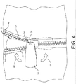
図4を参照すると、前記ファスナー配置12の正面図が示されており、前記ファスナー配置12は前記衣類10の一部を閉じている。前記ハンドル部分52と同様に、前記引手26はまた、男の親指のパッドの全てを実質的に受け入れるだけの十分なサイズである2つの対向する面を提供するように寸法決めされており、これにより着用者は前記引手26を容易につかんで操作することが可能である。図4には、前記スライダー28の周りの様々な前記引手26の回転位置が示されている。特に、前記引手26の3つの位置が図4に示されている。前記引手26は、右方向配向水平位から上方配向垂直位置まで矢印60に従って回転するように構成されている。同様に、前記引手26は、矢印62に従って前記右方向配向水平位から下方配向垂直位置まで回転することが可能である。前記引手26はまた、左方向配向水平位に回転することが可能であるが、図面の明確さのため、この位置は図示していない。ピン64(透視で示す)は前記引手26を前記スライダー28に結合して、前記引手26の前記スライダー28に対する枢動が可能となる。また、前記引手26は選択的に、当該引手26の下面に配置された摩擦部材(図示せず)を含むことが可能であり、これは前記スライダー28に配置された関連する摩擦部材(図示せず)と整合する。これらの摩擦部材は、引力の引っ張る力に抗して図4に示す位置に前記引手26を保持するのを助ける。
Referring to FIG. 4, a front view of the
前記ファスナー配置12の動作は、前記スライダーアセンブリ18と前記挿入ピンアセンブリ24とを係合させる着用者の行為を示す図5を参照しながら説明されている。このプロセスの間、前記衣類10の着用者は、右手で前記引手26をつかむことにより前記スライダーアセンブリ18をつかんでいる。前記着用者はまた、左手で前記挿入ピンアセンブリ24の把持部材32をつかんでいる。前記引手26のサイズおよびそれの前記スライダー28に対する予測可能な位置が与えられることにより、前記着用者は、右手により前記スライダーアセンブリ18の位置を素早く確かめることが可能である。加えて、前記挿入ピンアセンブリ24の前記外側顎48と前記内側顎50により、例え着用者の視界が妨げられていても、または前記挿入ピンアセンブリ24をつかむ能力が妨げられていても、前記着用者が左手で前記挿入ピンアセンブリ24および関連する挿入ピン38の位置を素早く確かめることが可能である。
The operation of the
着用者は、前記スライダーアセンブリ18および前記挿入ピンアセンブリ24の位置を確かめると、直ちに前記ファスナー配置12の2つの側を寄せ集めることが可能である。上述したように、前記把持部材32の開口54は、漏斗形状開口内の前記距離65(図3を参照)で定義される点まで受け入れるように構成されている。従って、前記挿入ピンアセンブリ24は、前記挿入ピン38を前記スライダーアセンブリ18内部に位置付けるのを補助する機能を提供するように有利に構成されている。この機能は、着用者の視界が妨げらている、または前記スライダーアセンブリ18および前記挿入ピンアセンブリ24をつかむ能力が妨げられているとき、特に有益である。
The wearer is able to gather the two sides of the
着用者が前記スライダーアセンブリ18および前記挿入ピンアセンブリ24を接合した後、当該着用者は、前記スライダーアセンブリ18と前記挿入ピンアセンブリ24との間に圧力を維持しながら、前記挿入ピンアセンブリ24の位置を調整することにより前記挿入ピン38を前記スライダー28の開口部(図示せず)と容易に一直線にすることが可能である。一直線になると、直ちに着用者は、前記挿入ピン38を前記スライダー28の中に挿入し、その後さらに前記保持箱体30の中に前記挿入ピン38が前記保持箱体30内部で最も低い位置になるまで挿入するため、前記スライダーアセンブリ18に対して前記挿入ピンアセンブリ24を下方に動かすことが可能である。前記衣類10を閉じるために、前記着用者は次に、前記スライダー28を前記ファスナー配置12の長さに沿って動かして、前記ファスナー配置12の右側14の務歯44と左側16の務歯46(図4を参照)を係合することが可能である。
After the wearer joins the
車輪を有するスライダー
図6を参照すると、衣類110に提供されたファスナー配置100の代替実施形態が示されている。図1〜5に示されたファスナー配置12と同様に、前記ファスナー配置100は前記衣類10の前部に提供されており、右側114と、左側116とを含む。スライダーアセンブリ118は、前記右側114に提供されており、前記ファスナー配置100の左側116と係合するように構成されている。
Slider with Wheels Referring to FIG. 6, an alternative embodiment of a
前記衣類110は、図1〜5の前記衣類10と同様に、前部右側部分120と、前部左側部分122とを含む。前記衣類100は、任意の様々な形状、例えばコート、シャツ、ズボン、または前記ファスナー配置100と着脱自在に結合される端部を有する1若しくはそれ以上の部分を有することが可能なその他の衣類を取ることが可能である。更に、前記ファスナー配置100は本明細書において衣類110に関連して示されているが、前記ファスナー配置100が多数の他の物品、例えばバッグ、靴、テントなどの物品と関連して使用することが可能であることは認識されるであろう。
The
前記スライダーアセンブリ118は一般に台形または三角形周囲形状を有するスライダー128を含み、そして、関連する引手126はまた同様の台形または三角形周囲形状を有する。前記スライダー128の形状が従来のY形状スライダーと異なることは認識されるであろう。従来のY形状のスライダーでは、前記スライダーの上端はより幅広くかつ非係合務歯が前記スライダーに出入りするよに構成されており、一方下端はより細くかつ係合務歯が前記スライダーに出入りするように構成されている。対照的に、本明細書に開示されている前記スライダー128は、典型的なY形状スライダーと概して逆配置になっている。特に、前記スライダー128の下端は上端より幅が広い。このように、開示されたスライダー128では、係合務歯が前記スライダー128に出入りするように構成される前記スライダーの端部は、前記非係合務歯が前記スライダー128に出入りするように構成される前記スライダーの端部より幅が広い。
The
前記スライダー128は内部チャンバー132を有し、当該内部チャンバーは空洞154と、空洞156とを含む。前記空洞154内には、弓形窓151を通して見ることができる右車輪150が備わっている。前記右車輪150は、前記空洞154内でハブ160の周りを回転するように構成されている。同様に、前記空洞156内には、弓形窓153を通して見ることができる左車輪152が備わっている。前記左車輪152は、前記空洞156内でハブ162の周りを回転するように構成されている。前記スライダー128が移動し、務歯144および146が前記スライダー128を介して移動するとき、前記車輪150および152は前記務歯144および146の前記裏面170および172に接触する。前記務歯144および146が互いに係合および非係合するように移動する際、前記務歯144および146の裏面170および172との接触により、前記務歯144および146にわずかな枢動運動が起こる。特に、前記スライダー128が係合する方向に移動(すなわち、図6〜8の実施形態の上方に移動)するとき、前記車輪150および152の前記務歯144および146の裏面170および172との係合により、前記務歯144および146は互いに向かって係合状態になるように枢動される。加えて、前記スライダー128が反対方向に移動(すなわち、図6〜8の実施形態の下方に移動)するとき、前記車輪150および152と前記務歯144および146の裏面170および172との接触により、前記務歯144および146は互いに離れる方向に非係合状態になるように枢動される。前記車輪150および152の前記務歯144および146の裏面170および172との係合は、前記務歯144および146の係合および非係合を促進するだけでなく、使用者に固有の触知感覚を提供する。この触知感覚はまた、使用者に、前記ファスナー配置100が適切に機能している印を提供する。
The
続けて図6を参照すると、前記スライダー128の内部チャンバー132はまた、当該スライダーの上部に右ガイド162と、左ガイド164とを含む。前記右ガイド162は前記車輪150に隣接しており、一方前記左ガイド164は前記車輪152に隣接している。前記右ガイド162および前記左ガイド164は、前記スライダー128が上方に引っ張られる(図7を参照)際に前記ファスナー配置100の対向する両側の前記務歯144および146を互いに係合させるように導くように構成されている。特に、前記右側の務歯144が前記スライダー128の右開口部166に入る際、前記右ガイド162は前記務歯144の裏面170に接触して、前記務歯144を前記スライダー128の中央の方向に、および前記車輪150と前記車輪152との間の位置に向ける。同様に、前記左側の務歯146が前記スライダー128の左開口部168に入る際、前記左ガイド164は前記務歯146の裏面172に接触して、前記務歯146を前記スライダー128の中央の方向に、および前記車輪150と前記車輪152との間の位置に向ける。前記対向する務歯144および146が前記スライダー128の中央の方向に、および前記車輪150と前記車輪152との間に移動する際、前記務歯144および146は係合される。同様に、前記スライダー128が下方に引っ張られるとき、前記務歯が前記車輪150と前記車輪152との間から離れるようにかつ前記スライダー128の前記右開口部166および左開口部168に向かって移動する際、前記右ガイド162と前記左ガイド164との間に配置された三角形中央部材161は前記務歯144と前記務歯146とに分ける。
With continued reference to FIG. 6, the
前記内部チャンバー132はまた、前記スライダー128の底部に中央開口部169を含む。前記中央開口部169は、前記ファスナー配置100を閉じるときに前記スライダー128が上方に引っ張られる際、既に係合状態にある前記務歯144および146が前記内部チャンバー132から出ることが可能なように構成されている。同様に、前記中央開口部169は、前記ファスナー配置100を開くときに前記スライダー128が下方に引っ張られる際、前記務歯144および146が前記内部チャンバー132に入るのが可能なように構成されている。
The
前記引手126は、前記スライダー128に対して固定されたスタッド174にヒンジ接続されている。前記スタッド174は、前記スライダー128との一体形成が可能であり、または別個の構成要素として前記スライダー128に付属させることも可能である。貫通孔180は、前記引手126の補完的部分孔(図示せず)と一直線になる前記スタッド174に形成されている。ピン182は、前記引手126に設けられた前記補完的部分孔(図示せず)に延出する前記貫通孔180に配置されている。前記ピン182により、前記引手126は矢印184に従って前記スライダー128に対して枢動することが可能となる。
The
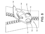
図7および8を参照すると、前記ファスナー配置100の追加の透視図が提供されている。図7において、前記引手126は、前記スライダー128に対する閉位置で示されている。前記引手126は前記スライダー128と実質的に同じ台形または三角形であるため、前記引手126は閉位置で前記スライダー128に好適な覆いを提供する。実質的に同じ周囲形状を有する前記引手126と前記スライダー128との結合は、前記ファスナー配置100に独特な外観を提供する。図8は、前記スライダー128に対して矢印184の方向に上方に枢動された前記引手126を示している。弓形窓151および153から、前記車輪150および152が見える。
With reference to FIGS. 7 and 8, additional perspective views of the
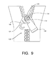
これから図9を参照すると、前記ファスナー配置100と類似のファスナー配置100'の代替実施形態の正面図が示されている。前記ファスナー配置100'は、引手126'と、スライダー128'とを含む。図9のファスナー配置100'は、前記引手126'の異なる動作および異なる形状を除いて、図6〜8のファスナー配置100と実質的に同じである。図9の実施形態において、前記スライダー128'は、前記引手126'の開口部176'を通って延出するスタッド174'を含む。前記引手126'は、ハブ186によって前記スライダー128'に枢動自在に搭載されており、前記引手126'が前記スライダー128'に対して矢印188に従って振れることが可能となる。
Referring now to FIG. 9, a front view of an alternative embodiment of a
図10を参照すると、前記ファスナー配置100に類似の別のファスナー配置100''の正面図が示されている。前記ファスナー配置100''は、前記引手126''が閉位置にあるときスライダー128''を覆うように構成される引手126''を含む。前記スライダー128''は、前記スライダー128''内部に配置された2つの車輪150''および152''を見せる中央窓151''を含む。前記中央窓151''は長方形または楕円形であり、車輪150''および152''の両方の少なくとも一部が見えるのに十分なサイズである。
Referring to FIG. 10, a front view of another
ファスナー配置100の動作は、図6、7、および8に関する以下の段落で説明される。しかしながら、同じ動作が前記ファスナー配置100'および100''(図9および10に示す)に適用されることも認識されるであろう。
The operation of the
閉じる動作
前記衣類110の着用者は前記引手126をつかみ、上方に矢印184に従て前記引手126を振る際に、前記衣類110の着用者は前記スライダー128を上方に移動させることができる。前記スライダー128が上方に移動する際、前記務歯144および146は、右開口部166および(前記スライダー128の反対側に位置する)左開口部168に入り、そして内部チャンバー132の中に入る。前記務歯144の裏面170は前記右ガイド162により導かれ、前記務歯146の裏面172は前記左ガイド164により導かれる。前記右ガイド162および前記左ガイド164は、前記引手126が上方に引っ張られる際に前記務歯144および146の係合を開始する。
Closing Action When the wearer of the
前記スライダー128の台形または三角形状および、前記右開口部166および前記左開口部168の形状、さらに前記右開口部166と前記務歯144との間の接合面および前記左開口部168と前記務歯146との間の接合面は、前記衣類110の布地が前記スライダー128内に入り込むの(スナッギング)を抑える。特に抗スナッギング性は、前記務歯144および146の裏面170および172と前記右ガイド162および前記左ガイド164との間の強固な接合面によって前記衣類110の一部が前記スライダー128内部に張り込む可能性を減らすことにより達成される。
The trapezoidal or triangular shape of the
更に、前記車輪150および152は、前記務歯144および146の裏面170および172に強固に接触する。前記スライダー128が上に引っ張られる際に、前記右車輪150は前記ハブ158の周りで時計回りの方向に回転し、一方前記左車輪152は、前記ハブ160の周りで反時計回りの方向に回転する。前記車輪150および152は、前記務歯144と前記務歯146との係合を達成させ、さらに係合務歯144および146が前記中央開口部169の外に出て、さらに前記スライダー128の外に出るのを促す。前記車輪150および152は、前記衣類110の着用者が前記引手126を上に引っ張る際に着用者に「滑らかさ」のフィードバックが提供され、これは前記ファスナー配置100の操作感を高める。
Further, the
開らく動作
着用者は、前記引手126を下に引っ張ることにより前記ファスナー配置100を開くことができる。最初に前記引手126は、前記ピン182の周りを前記矢印184に従って前記スライダー128に向かって動く。次に着用者は、前記引手126と前記スライダー128とを下方に引っ張ることができる。前記右車輪150は前記ハブ158の周りを反時計回りの方向に回転し、一方前記左車輪152は前記ハブ160の周りを時計回りの方向に回転る。前記車輪150および152と前記務歯144および146の裏面170および172との間の強固な接触のため、前記車輪150および152の回転は前記務歯144および146の分離の開始を促す。前記右ガイド162および前記左ガイド164と、前記右開口部166および前記左開口部168の形状とにより、前記スライダー128が下方に引っ張られる際に前記務歯144および146は完全に非係合化されるようになる。
The opening wearer can open the
前記車輪150および152と前記務歯144および146の裏面170および172との間の強固な接触のため、前記務歯144および146が前記中央開口部169に入る際、前記衣類110の布地の一部が前記スライダー128に入るおよび前記スライダー128の内部に入り込む(スナッギングの)可能性が大幅に減少する。
Because of the firm contact between the
更に、上記で提供された説明と同様に、前記車輪150および152は、着用者が前記スライダー128を下方に引っ張る際に、着用者に滑らかさのフィードバックを生成する。前記滑らかさのフィードバックは、先行技術のファスナー配置と比較しても着用者に上質の感覚を提供することが可能である。
Further, similar to the description provided above, the
折り畳み自在の引手
これから図11〜13を参照すると、衣類210に提供されたファスナー配置200が示されている。前記ファスナー配置12(図1を参照)と同様に、前記ファスナー配置200は前記衣類210の前部に提供されている。前記ファスナー配置200の二つの部分を係合するように構成されたスライダーアセンブリ218が提供されている。
Foldable pull handle Referring now to FIGS. 11-13, a
前記衣類210は、前記衣類10と類似しており(図1を参照)、前部右側部分220と、前部左側部分222とを含む。前記衣類210はまた、当該衣類210の首部に襟部212を含む。前記前部右側部分220および前記前部左側部分222は一般に、前記衣類210の底部から最上部まで、特に前記襟部212まで延長している。前記衣類210は、任意の様々な形状、例えばコート、シャツ、ズボン、または前記ファスナー配置200と着脱自在に結合される端部を有する1若しくはそれ以上の部分を有することが可能なその他の衣類を取ることが可能である。更に、前記ファスナー配置200の様々な実施形態が衣類210と関連して本明細書に示されているが、前記ファスナー配置200は、他の実施形態の例えばバック、靴、テントなどを含む多数の他の物品に関連して使用することが可能であることを理解されたい。
The
前記スライダーアセンブリ218は、スライダー228と、当該スライダー228に結合された引手226の形の引張部材とを含む。前記スライダー228は、前部230と、後部(図示せず)と、上部232とを含む。前記スライダー228の前部230は一般に前記衣類210の外側に面しており、前記スライダー228の後部は一般に前記衣類210の内側に面しており、前記スライダー228の上部232は一般に前記衣類の最上部(すなわち、前記襟部212の最上端)に面している。
The
スタッド274または他の結合部材は、前記スライダー228の前部230に提供される。前記スタッド274は、前記引手226の最上端に近接の孔部276を通って延出し、前記引手226を前記スライダー228に結合する。前記引手226のの孔部276は、前記スライダー228のスタッド274と協働して、前記引手226が矢印228に従って枢動するのを可能にする。
A
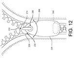
前記引手226は、例えば織物などの概して柔軟性を有するのある材料により構成されている。例えば、前記引手226のは、木綿素材、ポリエステル材料、混合物、または人が一般に皮膚に快適だと感じるその他の織物材料により構成されることが可能である。他の実施形態において、前記引手は、柔軟性を有するポリマー材料または当技術分野で知られている様々な他の任意の材料により構成されることが可能である。前記引手226は一般に、人の指で容易につかめるように設計および寸法決めされている。従って、前記引手226は、人の指および親指のパッドの大部分を受け入れるような形状およびサイズを有する。更に、以下でさらに詳細に説明されるように、前記引手226は、前記スライダー218の上部232を越えて引っ張り上げられ、かつ前記スライダー218の後部または前記襟部212の内部に接触するようもたらされるのに十分なサイズである。図12の実施形態において、前記引手226は概して楕円形または卵形を有する。しかしながら、他の実施形態において前記引手226が異なる形状であってもよいことを理解されたい。
The
図12に示すように、前記引手226は、当該引手226の低端に向いて配置された第1の保持部材290を含む。前記第1の保持部材290は図12に透視で示されており、多数の異なる実施形態に提供されることが可能である。例えば、少なくとも1実施形態において、前記第1の保持部材290は、前記引手226内部(例えば、前記引手のポケット内)にまたは前記引手226の表面に配置された磁石部材の形で提供される。他の例示的な実施形態において、前記第1の保持部材290は、前記引手226の表面に配置されたスナップ(留め金)(図示せず)、面ファスナー部材(図示せず)、または当業者に既知の他のタイプの付着機構であってもよい。
As shown in FIG. 12, the
前記第1の保持部材290を補完する第2の保持部材(図示せず)が、前記衣類210の内部に提供される。前記第1の保持部材290は、前記第2の保持部材に着脱自在に結合されるように構成される。例えば、前記引手226に設けられた前記第1の保持部材290が磁石である場合、前記第2の保持部材は、前記襟部212の内部に配置された補完的磁石部材であることが可能である。少なくとも1実施形態において、前記補完的磁石部材は、単純に前記スライダーアセンブリ218の後部にあり、前記スライダー218は鋼鉄若しくはその他の磁石金属材料により構成されている。少なくとも1代替実施形態において、前記第1の保持部材290は、面ファスナーのループ部分であってもよく、前記第2の保持部材は前記スライダー218の後部または前記襟部212の内部に配置された面ファスナーのフック部分であってもよい。更に別の例示的な実施形態において、前記第1の保持部材290は、スナップのボタンであってもよく、前記第2の保持部材は前記スナップの窪み部分であってもよい。前記第1および第2の保持部材の幾つかの可能な実施形態が本明細書に開示されているが、多数の追加の実施形態が可能なことを理解されたい。
A second holding member (not shown) that complements the first holding
ファスナー配置200の動作は図13を参照して説明されており、図13は引手226が衣類210の最上部にまで引っ張られて内側に折り畳まれた前記ファスナー配置200の正面図を示す。一般に、着用者は前記スライダー228を上下に引っ張るために、前記引手226をつかんで当該引手226を前記スライダー228に対して上方にまたは下方に振ることができる。。着用者は前記スライダー228を前記襟部212の最上部にまで引っ張ると、前記着用者は前記引手226を前記スライダー228の上部232を越えて上方に、または前記ファスナー配置200と皮膚との間の内部に、特に前記襟部212の内部の位置に折り畳むことが可能である。
The operation of the
前記引手226の折り畳み位置が前記スライダー228の上部232を覆うため、前記引手226は前記スライダー228の内面および前記ファスナー配置200の他の構成要素に対する快適さを着用者に提供することが可能である。前述したように、前記引手226は、所望の快適さを提供する柔らかい材料から構築することが可能である。少なくとも1実施形態において、前記柔らかい材料は、例えば綿またはポリエステル材料などの織物である。加えて、前記引手226はその折り畳み位置において、前記スライダー228を着用者の皮膚から分離することが可能であり、着用者が前記スライダー228を冷たく感じるような寒空の場合においては特に重要であり得る。
Because the folded position of the
前記第1の保持部材290は、前記引手226の位置をその折り畳み配置で保持するのに使用することが可能である。上述したように、前記第1の保持部材290は、前記引手226内部に施された磁気ストリップの形であることが可能であり、これにより前記スライダー228の内面と磁気的に整合するように構成される。代替的に、前記第1の保持部材290は、前記スライダー228の内面に配置された補完的ボタン(図示せず)とスナップ留めすることが可能なボタンであることが可能である。前記保持部材290に関する他の配置も可能であり、例えば補完的な面ファスナー部材が前記引手226と、前記スライダー228の内部または前記襟部212の内部とに配置される。
The
前述は前記ファスナー配置12、100、および200の幾つかの代替実施形態を提供しているが、前記ファスナー配置に関する多数の他の代替実施形態が可能であり、これは前記スライダー28と前記挿入ピンアセンブリ24とにかかわる追加の代替実施形態を含む。例えば、1代替実施形態において、前記スライダー28および前記挿入ピンアセンブリ24は、当該前記スライダー28と当該挿入ピンアセンブリ24との接合を補助する磁力を生成可能な補完的磁極を有する磁気材料から形成されることが可能である。
While the foregoing provides several alternative embodiments of the
前述の例示的な実施形態は前記ファスナー配置に関する多数の可能な実施形態のわずか数個であり、多数の追加の実施形態がまた可能であり、前述の実施形態がいかなる方法においても限定されるものと認識されるべきではないことを理解されたい。また、本明細書に記載の他の特徴および機能を組み込まないで得られることも可能な、本明細書に記載の特定の個別の特徴および機能の利点があることは理解されたい。さらに、上記で開示された実施形態と、他の特徴および機能、またはそれらの代替手段の様々な代替、修正、変更、または改善は、他の多くの異なる実施形態、システム、またはアプリケーションに望ましく組み合わせることが可能であることを理解されたい。本明細書で現在予期できないまたは予期しない代替、修正、変更、または改善は、後に当業者により行われるかもしれないが、それらもまた添付の特許請求の範囲により包含されることを意図されている。従って、あらゆる添付の特許請求の範囲の要旨および範囲は、明細書に含まれる実施形態の記載に限定されるべきではない。 The foregoing exemplary embodiments are just a few of the many possible embodiments for the fastener arrangement, many additional embodiments are also possible, and the foregoing embodiments are limited in any way It should be understood that it should not be recognized. It should also be understood that there are certain individual features and functional advantages described herein that may be obtained without incorporating other features and functions described herein. Moreover, various alternatives, modifications, changes, or improvements of the embodiments disclosed above and other features and functions, or alternatives thereof, are desirably combined in many other different embodiments, systems, or applications. It should be understood that it is possible. Alternatives, modifications, changes, or improvements that are currently unforeseen or unexpected herein may be made later by those skilled in the art and are also intended to be encompassed by the appended claims . Therefore, the spirit and scope of any appended claims should not be limited to the description of the embodiments contained in the specification.
Claims (16)
前記ファスナー装置の上端部と下端部との間に延長する複数のファスナー要素と、
前記ファスナー装置の上端部と下端部との間の前記複数のファスナー要素に沿ってスライドするように構成され、前部と、後部と、上部とを含むスライダーと、
前記スライダーの前部に結合された引手であって、前記スライダーが前記ファスナー装置の上端部にあるとき、前記スライダーの上部から前記ファスナー装置の上端を跨いで延伸し、かつ前記スライダーの後部に柔らかい材料からなるその先端が前記スライダーの後部に係合する位置に着脱自在に係合されるように構成されるものである、前記引手と
を有するファスナー装置。 A fastener device,
A plurality of fastener elements extending between an upper end and a lower end of the fastener device;
A slider configured to slide along the plurality of fastener elements between an upper end and a lower end of the fastener device, including a front portion, a rear portion, and an upper portion;
A pull handle coupled to the front portion of the slider, when the slider is at the upper end portion of the fastener device, extends from the upper portion of the slider across the upper end of the fastener device, and is soft at the rear portion of the slider A fastener device comprising: the pull handle, wherein the front end made of a material is configured to be detachably engaged at a position where the front end is engaged with the rear portion of the slider .
襟部と、
前部右側部分に沿って提供された複数の右ファスナー要素と、
前部左側部分に沿って提供された複数の左ファスナー要素と、
前部と、上部と、後部とを含むスライダーであって、当該スライダーは前記襟部まで上方に向かってスライド移動し、前記複数の右ファスナー要素を前記複数の左ファスナー要素と係合させるように構成され、さらに、下方に向かってスライド移動し、前記複数の右ファスナー要素を前記複数の左ファスナー要素から係合解除させるように構成されているものである、前記スライダーと、
前記スライダーに結合された柔らかい材料からなる引手であって、前記スライダーが前記襟部の位置にあるとき、前記スライダーの上部から前記ファスナー装置の上端を跨いで延伸し、かつ前記衣類の内側部分に着脱自在に結合されその先端が配置される、前記柔らかい材料からなる引手と
を有する衣類。 Clothing,
The collar,
A plurality of right fastener elements provided along the front right portion;
A plurality of left fastener elements provided along the front left portion;
A slider including a front portion, an upper portion, and a rear portion, wherein the slider slides upward to the collar portion so as to engage the plurality of right fastener elements with the plurality of left fastener elements. The slider further configured to slide downward and disengage the plurality of right fastener elements from the plurality of left fastener elements;
A handle made of a soft material coupled to the slider, and when the slider is in the position of the collar, extends from the top of the slider across the upper end of the fastener device, and on the inner part of the garment removably be freely coupled Ru is disposed a tip, garments having a pull tab made of the soft material.
Applications Claiming Priority (3)
| Application Number | Priority Date | Filing Date | Title |
|---|---|---|---|
| US12/947,685 US8528115B2 (en) | 2010-11-16 | 2010-11-16 | Zipper arrangement with foldable pull |
| US12/947,685 | 2010-11-16 | ||
| PCT/US2011/058731 WO2012067811A1 (en) | 2010-11-16 | 2011-11-01 | Zipper arrangement with foldable pull |
Publications (3)
| Publication Number | Publication Date |
|---|---|
| JP2014500769A JP2014500769A (en) | 2014-01-16 |
| JP2014500769A5 JP2014500769A5 (en) | 2014-12-25 |
| JP6018073B2 true JP6018073B2 (en) | 2016-11-02 |
Family
ID=46046446
Family Applications (1)
| Application Number | Title | Priority Date | Filing Date |
|---|---|---|---|
| JP2013539863A Active JP6018073B2 (en) | 2010-11-16 | 2011-11-01 | Fastener device having a foldable tension member |
Country Status (5)
| Country | Link |
|---|---|
| US (1) | US8528115B2 (en) |
| EP (1) | EP2640214A4 (en) |
| JP (1) | JP6018073B2 (en) |
| CN (1) | CN103313624B (en) |
| WO (1) | WO2012067811A1 (en) |
Families Citing this family (15)
| Publication number | Priority date | Publication date | Assignee | Title |
|---|---|---|---|---|
| US9681716B2 (en) | 2009-03-24 | 2017-06-20 | Travel Caddy, Inc. | Anti-theft carrying strap |
| US9854883B2 (en) | 2009-03-24 | 2018-01-02 | Travel Caddy, Inc. | Anti-theft carrying bag |
| US8925181B2 (en) | 2009-03-24 | 2015-01-06 | Travel Caddy, Inc. | Cut-proof anti-theft bag construction |
| US9675153B2 (en) | 2009-03-24 | 2017-06-13 | Travel Caddy, Inc. | Anti-theft expansion panel for a carrying bag |
| US10010144B2 (en) | 2009-03-24 | 2018-07-03 | Travel Caddy, Inc. | Anti-theft security panel for a carrying bag |
| US9854890B2 (en) | 2009-03-24 | 2018-01-02 | Travel Caddy, Inc. | Anti-theft carrying bag |
| US8381369B2 (en) * | 2011-01-26 | 2013-02-26 | Lien-Chou Wang | Roller zipper slide |
| US8661629B2 (en) * | 2011-01-26 | 2014-03-04 | Genmore Zipper Corporation | Roller-loaded zipper slide |
| CH707394B1 (en) * | 2012-12-19 | 2015-09-15 | Lk Internat Ag | Sports jacket with device for thermal regulation. |
| WO2017015209A1 (en) | 2015-07-21 | 2017-01-26 | Travel Caddy, Inc., D/B/A Travelon | Interlocking zipper pull tabs and fastening system |
| US20170251736A1 (en) * | 2016-03-04 | 2017-09-07 | Bobbie Jean Harbert | Apparel configurable into bedding or having removable bedding |
| US20190110560A1 (en) * | 2017-10-12 | 2019-04-18 | Pvh Corp. | Easy releasing zipper |
| IL257095A (en) * | 2018-01-23 | 2018-03-29 | Zip It Ltd | Slide fastener |
| US11013298B2 (en) | 2018-07-18 | 2021-05-25 | Nike, Inc. | Releasable fastener |
| US11432622B2 (en) | 2020-03-17 | 2022-09-06 | Nike, Inc. | Releasable coupling device |
Family Cites Families (103)
| Publication number | Priority date | Publication date | Assignee | Title |
|---|---|---|---|---|
| US479050A (en) * | 1892-07-19 | Albert l | ||
| US3047925A (en) * | 1960-11-30 | 1962-08-07 | Peter J Merino | Reversible zipper |
| US3284864A (en) * | 1965-04-26 | 1966-11-15 | Robert B Howell | Slider |
| US3448463A (en) * | 1967-07-03 | 1969-06-10 | Gaetano Milone | Double zippered garments |
| JPS4839367Y1 (en) * | 1970-07-10 | 1973-11-20 | ||
| US3641634A (en) * | 1970-12-02 | 1972-02-15 | Yoshida Kogyo Kk | Slider for zip fasteners |
| JPS4842243Y1 (en) * | 1970-12-31 | 1973-12-08 | ||
| US3754306A (en) * | 1971-08-04 | 1973-08-28 | J Cirone | Anchor for zipper handle |
| JPS5089505U (en) * | 1973-12-24 | 1975-07-29 | ||
| US4015296A (en) * | 1976-03-17 | 1977-04-05 | Frank Malick | Elastic stocking |
| US4142275A (en) | 1977-05-16 | 1979-03-06 | Alwin Krauer | Slide fasteners |
| US4232429A (en) | 1978-09-07 | 1980-11-11 | Friedberg Martin F | Sliding fastener |
| US4261082A (en) | 1979-08-03 | 1981-04-14 | Minoru Kamiya | Slide fastener for preventing jamming of foreign matter |
| US4309798A (en) | 1980-01-07 | 1982-01-12 | Fraga John B | Fail-safe slide fastener |
| DE3507546C1 (en) | 1985-03-04 | 1986-07-17 | Reiner 6903 Neckargemünd Hoerkens | Lockable jewelry chain |
| JPH0510654Y2 (en) * | 1987-04-13 | 1993-03-16 | ||
| JPH0436656Y2 (en) * | 1987-05-22 | 1992-08-28 | ||
| JPS6420805A (en) | 1987-07-14 | 1989-01-24 | Yoshida Kogyo Kk | Slide fastener |
| US4918794A (en) * | 1987-10-13 | 1990-04-24 | Life-Link International, Inc. | Pull for slide fastener sliders |
| JPH01121410U (en) * | 1988-02-12 | 1989-08-17 | ||
| US4819308A (en) | 1988-03-14 | 1989-04-11 | Baroky Julian K | Zipper guard |
| FR2632829B1 (en) | 1988-06-17 | 1990-11-09 | Salomon Sa | ZIPPER CLOSURE FOR SPORTSHOES, PARTICULARLY FOR CROSS-COUNTRY SKIING |
| US4928363A (en) * | 1989-06-26 | 1990-05-29 | Wayne Easton | Zipper securing ring |
| JPH0355717U (en) | 1989-10-02 | 1991-05-29 | ||
| US4997222A (en) | 1990-01-25 | 1991-03-05 | Troy Reed | Zipper pull |
| JPH0416908U (en) * | 1990-06-01 | 1992-02-12 | ||
| US5079809A (en) | 1990-09-14 | 1992-01-14 | Teich Garland N | Anti-binding zipper slider |
| FR2677858B1 (en) * | 1991-06-21 | 1993-10-15 | Salomon Sa | DRAWER FOR ZIPPER CLOSURE. |
| US5181299A (en) | 1991-12-10 | 1993-01-26 | Huang Hung C | Zipper having anti-jam flaps |
| US5263201A (en) * | 1992-12-02 | 1993-11-23 | Hood Stephen G | Trousers having zipper slide with button |
| JPH06189810A (en) * | 1992-12-22 | 1994-07-12 | Yoshida Kogyo Kk <Ykk> | Pull tab of slider for slide fastener and manufacture of pull tab |
| US5497535A (en) | 1994-06-06 | 1996-03-12 | Kloor; Patrick W. | Non-binding zipper |
| JP3384216B2 (en) * | 1995-11-30 | 2003-03-10 | ワイケイケイ株式会社 | String body |
| US5745960A (en) | 1996-06-18 | 1998-05-05 | Walrus, Inc. | Zipper apparatus and method facilitating maintenance and repair |
| JP3639393B2 (en) * | 1996-11-08 | 2005-04-20 | 大阪美錠工業株式会社 | Slide handle for slide fastener |
| JP3580337B2 (en) | 1997-02-28 | 2004-10-20 | Ykk株式会社 | Slider for hidden slide fastener |
| US6026546A (en) | 1997-03-28 | 2000-02-22 | Lund & Company | Figurines attached to a zipper |
| US6026547A (en) * | 1997-05-15 | 2000-02-22 | O'donnell Kiely; Alice Mary | Immobilized alignment closure system |
| JPH1170007A (en) | 1997-08-29 | 1999-03-16 | Ykk Corp | Slide fastener tape and stringer for slide fastener |
| GB2332238A (en) | 1997-12-12 | 1999-06-16 | Ykk Europ Ltd | Zip fastener having alignment holes |
| US6189249B1 (en) * | 1997-12-16 | 2001-02-20 | Christopher V. Hughes | Security tag device |
| JP3733232B2 (en) | 1998-01-30 | 2006-01-11 | Ykk株式会社 | Male and female locking device with tape |
| TW379170B (en) | 1998-05-07 | 2000-01-11 | Kang Young Chul | Color slide fastener and method and apparatus producing color slide fastener |
| JP2000037214A (en) * | 1998-07-13 | 2000-02-08 | East San Botan Internatl Ltd | Accessory and its production |
| JP2000262309A (en) | 1999-03-17 | 2000-09-26 | Ykk Corp | Slider for slide fastener |
| JP3611183B2 (en) | 1999-09-30 | 2005-01-19 | Ykk株式会社 | Slide handle for slide fastener |
| JP3599617B2 (en) | 1999-10-29 | 2004-12-08 | Ykk株式会社 | Slide handle for slide fastener |
| JP2001178508A (en) | 1999-12-27 | 2001-07-03 | Ykk Corp | Fastener element for slide fastener |
| US6421834B2 (en) * | 2000-01-10 | 2002-07-23 | Robert J. Kester | Survival jacket |
| JP2001303389A (en) * | 2000-04-28 | 2001-10-31 | Nippon Dam Kk | Woven product weaving name or the like on front and back |
| US6571432B1 (en) | 2000-11-09 | 2003-06-03 | Salomon S.A. | Hidden closure |
| US6536084B2 (en) | 2001-01-30 | 2003-03-25 | Ideal Fastener Corporation | Low profile integrated omega zipper closure system |
| US6453521B1 (en) | 2001-03-08 | 2002-09-24 | Delphi Oracle Corp. | Multiple pitch zipper |
| US7204001B2 (en) | 2001-04-27 | 2007-04-17 | Paragon Luggage, Inc. | Zipper pull tab |
| JP3733309B2 (en) | 2001-09-25 | 2006-01-11 | Ykk株式会社 | Slider for slide fastener |
| US6647551B2 (en) * | 2001-10-15 | 2003-11-18 | The United States Of America As Represented By The Secretary Of The Army | Reversible garment |
| US6588072B1 (en) | 2001-12-31 | 2003-07-08 | Yu-Pau Lin | Zipper slide |
| JP3733332B2 (en) | 2002-01-25 | 2006-01-11 | Ykk株式会社 | Hidden slide fastener with open fitting insert |
| US6701584B2 (en) | 2002-03-21 | 2004-03-09 | The Coleman Company, Inc. | Zipper guard |
| US7293334B2 (en) | 2002-03-21 | 2007-11-13 | The Coleman Company, Inc. | Integral zipper slide and guard |
| US6928703B2 (en) | 2002-03-25 | 2005-08-16 | Robin Petravic | Sealed slider adjustment mechanism |
| ITTO20020688A1 (en) | 2002-07-31 | 2004-02-01 | Ykk Italia Spa | TRACTION DEVICE WITH COVERING ELEMENT, |
| FR2843857B1 (en) | 2002-08-29 | 2004-11-05 | Salomon Sa | ZIPPER WITH CURSOR LOCK |
| US20040088834A1 (en) | 2002-09-13 | 2004-05-13 | Yu Chih Hsiung | Zipper |
| JP3934027B2 (en) | 2002-10-23 | 2007-06-20 | Ykk株式会社 | Slide fastener |
| US7043802B2 (en) | 2003-01-30 | 2006-05-16 | Illinois Tool Works Inc | Zipper pull with whistle |
| JP3957071B2 (en) | 2003-02-25 | 2007-08-08 | Ykk株式会社 | Slide fastener |
| JP4387124B2 (en) | 2003-05-30 | 2009-12-16 | Ykk株式会社 | Slide fastener stringer using the same slide fastener tape |
| FR2856253B1 (en) | 2003-06-20 | 2005-08-05 | Salomon Sa | CLOSURE SYSTEM FOR GARMENT-TYPE ARTICLE |
| US20050015850A1 (en) * | 2003-07-02 | 2005-01-27 | Ellen Waldman | Head and neck garment |
| US7111714B1 (en) | 2003-07-07 | 2006-09-26 | Nike, Inc. | Slide fastener pull handle |
| US20050035605A1 (en) * | 2003-08-13 | 2005-02-17 | Kathryn Vanderwater-Piercy | Security device for luggage |
| JP4062617B2 (en) | 2003-10-17 | 2008-03-19 | Ykk株式会社 | Top of line slide fastener |
| CH696619A5 (en) | 2003-10-28 | 2007-08-31 | Crelux Holding Sa | for zipper has a slider with two pull tabs and a single fork to unlock the slider. |
| TWI243658B (en) | 2003-11-19 | 2005-11-21 | Ykk Corp | Slide fastener slider |
| JP4145252B2 (en) | 2004-01-29 | 2008-09-03 | Ykk株式会社 | Slider for slide fastener |
| CN2733961Y (en) * | 2004-02-02 | 2005-10-19 | 黄玉莹 | Magnetic slide-proof zip head |
| US7036190B2 (en) | 2004-03-19 | 2006-05-02 | Nike, Inc. | Closure mechanism for apparel |
| EP1827159B1 (en) | 2004-11-16 | 2008-03-26 | Riri S.A. | Slider for zip fastener with interchangeable pull-tab |
| US20060107441A1 (en) * | 2004-11-22 | 2006-05-25 | Houdroge Waleed M | Reversible jeans for men and women |
| US7886368B2 (en) * | 2004-12-06 | 2011-02-15 | Tony Hood | Garment backpack |
| US20060218758A1 (en) | 2005-04-05 | 2006-10-05 | Mo-Hsin Chang | Zipper |
| JP2006288960A (en) * | 2005-04-14 | 2006-10-26 | Inter Linx:Kk | Zipper with shield |
| US20060242804A1 (en) | 2005-04-28 | 2006-11-02 | Griffiths John M | Zipper pull tab attachment |
| JP2006320642A (en) | 2005-05-20 | 2006-11-30 | Ykk Corp | Zipper chain |
| JP4646783B2 (en) | 2005-11-16 | 2011-03-09 | Ykk株式会社 | Hidden slide fastener slider |
| US20070135953A1 (en) | 2005-12-14 | 2007-06-14 | Todd Crow | Zipper speaker |
| US20070289110A1 (en) | 2006-06-19 | 2007-12-20 | Sean Christopher Bekeschus | Slide fastener for garments |
| US7313847B1 (en) | 2006-07-14 | 2008-01-01 | Christopher Theodore Felix | CTF flip-N-zip slider |
| US20080040837A1 (en) * | 2006-08-18 | 2008-02-21 | King Rodney L | Airtight waterproof zipper, method for mounting the same, and article incorporating the same |
| US20080127395A1 (en) * | 2006-12-01 | 2008-06-05 | Blauer Manufacturing Company, Inc. | Front closure for reversible outerwear |
| JP4447599B2 (en) | 2006-12-28 | 2010-04-07 | Ykk株式会社 | Top stopper for slide fastener |
| JP4731509B2 (en) | 2007-03-02 | 2011-07-27 | Ykk株式会社 | Teeth for slide fasteners and slide fasteners |
| JP4799452B2 (en) | 2007-03-16 | 2011-10-26 | Ykk株式会社 | Slider for slide fastener |
| ES2359533T3 (en) | 2007-07-10 | 2011-05-24 | Ykk Corporation | DOUBLE FACE METAL ELEMENT AND ZIPPER CLOSURE. |
| JP4906637B2 (en) | 2007-08-20 | 2012-03-28 | Ykk株式会社 | Hidden slide fastener slider with split fitting |
| JP2009056076A (en) | 2007-08-31 | 2009-03-19 | Ykk Corp | Slider for slide fastener |
| JP4906644B2 (en) | 2007-09-07 | 2012-03-28 | Ykk株式会社 | Slide fastener |
| US20090077774A1 (en) | 2007-09-21 | 2009-03-26 | Chi Ju Lee | Slide fastener device having warning device |
| JP2009087441A (en) * | 2007-09-28 | 2009-04-23 | Hoya Corp | Manufacturing method of glass substrate for magnetic disk, and manufacturing method of magnetic disk |
| PL2044855T3 (en) | 2007-10-04 | 2011-05-31 | Riri Sa | A fluid-tight slide fastener |
| ES2356862T3 (en) | 2008-03-13 | 2011-04-13 | Riri S.A. | SLIDING CLOSURE AND TOP BUMPER FOR SLIDING CLOSURE. |
| US8695178B2 (en) | 2008-06-30 | 2014-04-15 | Ykk Corporation | Slide fastener |
-
2010
- 2010-11-16 US US12/947,685 patent/US8528115B2/en active Active
-
2011
- 2011-11-01 EP EP11841346.7A patent/EP2640214A4/en active Pending
- 2011-11-01 JP JP2013539863A patent/JP6018073B2/en active Active
- 2011-11-01 CN CN201180064796.1A patent/CN103313624B/en active Active
- 2011-11-01 WO PCT/US2011/058731 patent/WO2012067811A1/en active Application Filing
Also Published As
| Publication number | Publication date |
|---|---|
| CN103313624B (en) | 2016-01-06 |
| EP2640214A1 (en) | 2013-09-25 |
| US20120117709A1 (en) | 2012-05-17 |
| WO2012067811A1 (en) | 2012-05-24 |
| EP2640214A4 (en) | 2017-11-08 |
| JP2014500769A (en) | 2014-01-16 |
| US8528115B2 (en) | 2013-09-10 |
| CN103313624A (en) | 2013-09-18 |
Similar Documents
| Publication | Publication Date | Title |
|---|---|---|
| JP6018073B2 (en) | Fastener device having a foldable tension member | |
| US8590118B2 (en) | Closure arrangement with opening in stationary member | |
| US7721353B2 (en) | Hand covering with a hood and a movement mechanism | |
| US8484811B2 (en) | Zipper arrangement with wheeled slider | |
| US10420399B2 (en) | Zipper closure facilitator assembly for articles of apparel | |
| AU2009347196B2 (en) | Device for opening and closing a zipper | |
| EP2405781B1 (en) | Device for opening and closing a zipper | |
| JP2003201609A (en) | Parka | |
| WO2020227802A1 (en) | Zipper closure facilitator assembly for articles of apparel | |
| JP3094773U (en) | Golf gloves | |
| JP5605874B1 (en) | Clothing that allows the sleeve to be removed | |
| JP3080123U (en) | Cosmetic pants | |
| JP3172724U (en) | Restraining gloves | |
| JP3176655U (en) | Scratch prevention gloves | |
| JP3106219U (en) | clothes | |
| JP3168800U (en) | Removable upper garment | |
| JP2002173810A (en) | Wear | |
| JP2003219906A (en) | Shoulder strap of shoulder bag | |
| TWM440013U (en) | Adjusted buckle |
Legal Events
| Date | Code | Title | Description |
|---|---|---|---|
| A521 | Request for written amendment filed |
Free format text: JAPANESE INTERMEDIATE CODE: A523 Effective date: 20141101 |
|
| A621 | Written request for application examination |
Free format text: JAPANESE INTERMEDIATE CODE: A621 Effective date: 20141101 |
|
| A977 | Report on retrieval |
Free format text: JAPANESE INTERMEDIATE CODE: A971007 Effective date: 20150713 |
|
| A131 | Notification of reasons for refusal |
Free format text: JAPANESE INTERMEDIATE CODE: A131 Effective date: 20150804 |
|
| A521 | Request for written amendment filed |
Free format text: JAPANESE INTERMEDIATE CODE: A523 Effective date: 20151104 |
|
| A131 | Notification of reasons for refusal |
Free format text: JAPANESE INTERMEDIATE CODE: A131 Effective date: 20160419 |
|
| A521 | Request for written amendment filed |
Free format text: JAPANESE INTERMEDIATE CODE: A523 Effective date: 20160714 |
|
| TRDD | Decision of grant or rejection written | ||
| A01 | Written decision to grant a patent or to grant a registration (utility model) |
Free format text: JAPANESE INTERMEDIATE CODE: A01 Effective date: 20160906 |
|
| A61 | First payment of annual fees (during grant procedure) |
Free format text: JAPANESE INTERMEDIATE CODE: A61 Effective date: 20160929 |
|
| R150 | Certificate of patent or registration of utility model |
Ref document number: 6018073 Country of ref document: JP Free format text: JAPANESE INTERMEDIATE CODE: R150 |
|
| R250 | Receipt of annual fees |
Free format text: JAPANESE INTERMEDIATE CODE: R250 |
|
| R250 | Receipt of annual fees |
Free format text: JAPANESE INTERMEDIATE CODE: R250 |
|
| R250 | Receipt of annual fees |
Free format text: JAPANESE INTERMEDIATE CODE: R250 |
|
| R250 | Receipt of annual fees |
Free format text: JAPANESE INTERMEDIATE CODE: R250 |
|
| R250 | Receipt of annual fees |
Free format text: JAPANESE INTERMEDIATE CODE: R250 |