JP6014331B2 - Hot wire feeder - Google Patents
Hot wire feeder Download PDFInfo
- Publication number
- JP6014331B2 JP6014331B2 JP2012009937A JP2012009937A JP6014331B2 JP 6014331 B2 JP6014331 B2 JP 6014331B2 JP 2012009937 A JP2012009937 A JP 2012009937A JP 2012009937 A JP2012009937 A JP 2012009937A JP 6014331 B2 JP6014331 B2 JP 6014331B2
- Authority
- JP
- Japan
- Prior art keywords
- wire
- cooling
- power supply
- unit
- hot wire
- Prior art date
- Legal status (The legal status is an assumption and is not a legal conclusion. Google has not performed a legal analysis and makes no representation as to the accuracy of the status listed.)
- Active
Links
Images

Landscapes
- Arc Welding In General (AREA)
- Laser Beam Processing (AREA)
Description
本発明は、例えば、レーザ光を用いたレーザ溶接において、レーザ光を照射した溶接部分に通電加熱しつつ溶接ワイヤを供給するのに用いられるホットワイヤ供給装置に関するものである。 The present invention relates to, for example, a hot wire supply apparatus used for supplying a welding wire while energizing and heating a welded portion irradiated with laser light in laser welding using laser light.
従来、上記したようなホットワイヤ供給装置としては、例えば、特許文献1に記載されたものがある。
Conventionally, as a hot wire supply apparatus as described above, for example, there is one described in
このホットワイヤ供給装置は、ホットワイヤTIG溶接において、溶接ワイヤを通電加熱しつつ溶接部分に送り込むのに用いられるもので、溶接ワイヤに通電することで得るジュール熱は、TIG溶接の補助熱源として用いられる。 This hot wire supply device is used in hot wire TIG welding to feed the welding wire to the welding part while energizing and heating. Joule heat obtained by energizing the welding wire is used as an auxiliary heat source for TIG welding. It is done.
このホットワイヤ供給装置は、溶接ワイヤの送給機構と、この送給機構から送出される溶接ワイヤをガイドするコンジットチューブの先端に固定されたワイヤトーチと、このワイヤトーチに電源を供給するワイヤ加熱電源を備えている。 The hot wire supply device includes a welding wire feeding mechanism, a wire torch fixed to a distal end of a conduit tube that guides a welding wire delivered from the feeding mechanism, and a wire heating power source that supplies power to the wire torch. I have.
ワイヤトーチは、溶接部分に向けて溶接ワイヤを案内支持するセラミックチップと、このワイヤトーチ内で溶接ワイヤと接触して給電する給電電極を具備しており、この給電電極に対するワイヤ加熱電源からの給電は給電ケーブルを介して行われるようになっている。 The wire torch includes a ceramic tip that guides and supports the welding wire toward the welded portion, and a power supply electrode that contacts and feeds the welding wire in the wire torch. Power supply from the wire heating power source to the power supply electrode is a power supply. This is done via a cable.
上記したホットワイヤ供給装置において、大電流を溶接ワイヤに通電する都合上、給電ケーブルには大径で且つ剛性の高い被覆部材が使用されることから、その取り回しが面倒であるのに加えて、僅かな接触でもワイヤトーチの先端のセラミックチップが大きく動いてしまい、アライメントをし直さなくてはならないという問題があった。 In the above hot wire supply device, for the convenience of energizing the welding wire with a large current, since a coating member having a large diameter and high rigidity is used for the power supply cable, in addition to being troublesome to handle, Even with a slight contact, the ceramic chip at the tip of the wire torch moves greatly, and there is a problem that alignment must be performed again.
また、溶接ワイヤに通電することで生じるジュール熱によって、セラミックチップが激しく消耗することから、安価ではないセラミックチップを頻繁に交換する必要があり、その分だけ、ランニングコストの上昇を招いてしまうという問題があり、これらの問題を解決することが従来の課題となっていた。 In addition, since the ceramic chip is exhausted vigorously due to Joule heat generated by energizing the welding wire, it is necessary to frequently replace the ceramic chip which is not cheap, and this will increase the running cost. There are problems, and solving these problems has been a conventional problem.
本発明は、上記した従来の課題に着目してなされたもので、作業性の向上を実現することができるのに加えて、ランニングコストの上昇を抑えることが可能であるホットワイヤ供給装置を提供することを目的としている。 The present invention has been made paying attention to the above-described conventional problems, and provides a hot wire supply device capable of realizing an improvement in workability and suppressing an increase in running cost. The purpose is to do.
本発明の請求項1に係る発明は、溶接ワイヤに通電して加熱しつつ溶融部分に送り込むホットワイヤ供給装置であって、前記溶接ワイヤの送給機構と、この送給機構から送出される前記溶接ワイヤの先端部を前記溶融部分に向けて案内支持するノズルチップと、このノズルチップ近傍に位置する給電部と、この給電部を介して前記溶接ワイヤに電源を供給するワイヤ加熱電源を備えたホットワイヤ供給装置において、冷却媒体、例えば、冷却水を通過させることで前記ノズルチップ及び前記給電部を冷却する冷却部を設けると共に、この冷却部に対する冷却媒体の供給排出を行う冷却媒体流路のうちの前記冷却部を通過した冷却水を排出する側の冷却媒体流路を前記ワイヤ加熱電源から前記給電部に対する給電を行う給電ケーブルに一体的に配置した構成としたことを特徴としており、この構成のホットワイヤ供給装置を前述した従来の課題を解決するための手段としている。
The invention according to
本発明の請求項2に係るホットワイヤ供給装置では、前記給電ケーブルに一体的に配置される前記冷却部を通過した冷却水を排出する側の前記冷却媒体流路の一部を冷却ホースとし、この冷却ホースに前記給電ケーブルを収納してある構成としている。 In the hot wire supply device according to claim 2 of the present invention, a part of the cooling medium flow path on the side of discharging the cooling water that has passed through the cooling unit that is integrally disposed in the power supply cable is a cooling hose, The power supply cable is housed in the cooling hose.
本発明に係るホットワイヤ供給装置は、CO2レーザ光やYAGレーザ光、或いはレーザダイオードから出射したレーザ光などのレーザ光を用いたレーザホットワイヤ溶接に用いることができるほか、ホットワイヤTIG溶接にも適用可能である。 The hot wire supply apparatus according to the present invention can be used for laser hot wire welding using a laser beam such as a CO 2 laser beam, a YAG laser beam, or a laser beam emitted from a laser diode, and also for hot wire TIG welding. Is also applicable.
本発明に係るホットワイヤ供給装置において、レーザ光を照射することで溶融した母材の溶接部分に対して、給電部からの通電によって加熱されて溶融寸前となった溶接ワイヤの先端部をノズルチップから供給すると、溶接ワイヤの先端部も最小限の熱を受けて溶融することから、高品質の溶接が成されることとなる。 In the hot wire supply apparatus according to the present invention, the tip of the welding wire that has been heated by energization from the power supply unit and is about to be melted is welded to the nozzle tip with respect to the welded portion of the base material melted by irradiating the laser beam. Since the tip of the welding wire also receives a minimum amount of heat and melts, high-quality welding is achieved.
この際、ノズルチップ及び給電部は、冷却媒体が通過する冷却部によっていずれも冷却されているので、ノズルチップの消耗が少なく抑えられ、その結果、ノズルチップの交換頻度が減少する分だけ、ランニングコストの低減が図られるのに加えて、ノズルチップに、安価な例えば銅製のものを用いることができるので、ランニングコストのより一層の低減が図られることとなる。 At this time, since the nozzle tip and the power feeding unit are both cooled by the cooling unit through which the cooling medium passes, the consumption of the nozzle tip is suppressed, and as a result, the nozzle chip replacement frequency is reduced. In addition to cost reduction, since the nozzle tip can be made of, for example, copper, the running cost can be further reduced.
また、冷却部に対する冷却媒体の供給排出を行う冷却媒体流路の一部が、ワイヤ加熱電源と給電部とを結ぶ給電ケーブルに一体的に配置してあることから、給電ケーブルを冷却し得る分だけ、給電ケーブルに小径で且つ剛性の低い被覆部材を用いることができるようになり、したがって、給電ケーブルの取り回しが容易になる。加えて、このような柔軟性のある給電ケーブルは、接触等の負荷に強いことから、アライメントのし直し等の作業がほとんど不要なものとなる。 In addition, since a part of the cooling medium flow path for supplying and discharging the cooling medium to and from the cooling unit is integrally disposed on the power supply cable connecting the wire heating power source and the power supply unit, the power supply cable can be cooled. Therefore, it becomes possible to use a covering member having a small diameter and low rigidity for the power supply cable, and therefore, the power supply cable can be easily routed. In addition, such a flexible power supply cable is resistant to loads such as contact, and therefore requires almost no work such as realignment.
本発明の請求項1に係るホットワイヤ供給装置では、上記した構成としているので、溶接部分に対するホットワイヤ供給時における作業性の向上を実現することができると共に、ランニングコストの低減を実現することが可能であるという非常に優れた効果がもたらされる。
The hot wire supply device according to
また、本発明の請求項2に係るホットワイヤ供給装置では、冷却ホースに給電ケーブルを収納した構成としているので、配管配線作業の複雑さを招くことなく給電ケーブルを冷却し得ることとなる。 In the hot wire supply device according to claim 2 of the present invention, since the power supply cable is housed in the cooling hose, the power supply cable can be cooled without incurring the complexity of the piping work.
以下、本発明を図面に基づいて説明する。
図1及び図2は本発明に係るホットワイヤ供給装置の一実施例を示しており、この実施例では、本発明に係るホットワイヤ供給装置をレーザホットワイヤ溶接機に採用した場合を例に挙げて説明する。
Hereinafter, the present invention will be described with reference to the drawings.
1 and 2 show an embodiment of a hot wire supply apparatus according to the present invention. In this embodiment, the hot wire supply apparatus according to the present invention is applied to a laser hot wire welding machine as an example. I will explain.
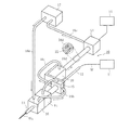
図1に示すように、このレーザホットワイヤ溶接機1は、チラー2により温度管理されたレーザ発振器3と、このレーザ発振器3と光ファイバー4を介して接続するレーザトーチ5と、このレーザトーチ5を移動させる図示しない駆動機構を備えており、レーザトーチ5は、光ファイバー4を介して伝達されるレーザ発振器3からの出力をレーザビームLBにして母材Bに照射してこの母材Bの表面BSを溶融させるようになっている。
As shown in FIG. 1, the laser hot
このレーザホットワイヤ溶接機1に採用されるホットワイヤ供給装置10は、レーザトーチ5から照射されるレーザビームLBの移動に伴って移動する母材Bの表面BSの溶融部分BWに対して、溶接ワイヤWを連続して供給するものであり、溶接ワイヤWの送給機構11と、この送給機構11からコンジットチューブ12を介して送給される溶接ワイヤWの先端部Waを溶融部分BWに向けて案内支持するノズルチップ13と、このノズルチップ13近傍に位置する給電部14と、この給電部14を介して溶接ワイヤWに電源を供給することで溶接ワイヤWの先端部Waを溶融寸前とするワイヤ加熱電源15を備えている。
The hot
また、ホットワイヤ供給装置10は、図2にも示すように、ノズルチップ13及び給電部14の間に配置される冷却部16を備えており、この冷却部16は、ポンプ17から冷却ホース(流路)18aを介して供給される冷却水(冷却媒体)が通過することでノズルチップ13及び給電部14の双方を冷却するようになっている。
Further, as shown in FIG. 2, the hot
この場合、冷却部16を通過して排出される冷却水は、冷却ホース18b,ベースブロック19,冷却ホース18c,接続ブロック20,冷却ホース18d,中間接続ブロック21及び冷却ホース18eを順次介してポンプ17に戻るようになっており、冷却ホース18dには、ワイヤ加熱電源15側の中間接続ブロック21から給電部14側の接続ブロック20に対する給電を行う給電ケーブル22が収納してある。
In this case, the cooling water discharged through the
上記したレーザホットワイヤ溶接機1により溶接を行うに際しては、レーザトーチ5から出射したレーザビームLBを母材Bに照射すると、母材Bは均一にそして最小限の熱を受けて表面BSないしその近傍のみが溶融する。
When welding is performed by the laser hot
次いで、図示しない駆動機構の動作によってレーザトーチ5とともにレーザビームLBを移動させる。このレーザビームLBの移動に伴って移動する母材Bの表面BSの溶融部分BWに対して、ホットワイヤ供給装置10の給電部14からの通電によって加熱されて溶融寸前となった溶接ワイヤWの先端部Waをノズルチップ13から連続して供給する。
Next, the laser beam LB is moved together with the
そして、この溶融寸前とした溶接ワイヤWに対してレーザビームLBによる加熱を行うと、溶接ワイヤWの先端部Waも最小限の熱を受けて溶融することから、高品質の溶接が成されることとなる。 When the welding wire W just before melting is heated by the laser beam LB, the tip end portion Wa of the welding wire W is melted by receiving a minimum amount of heat, so that high-quality welding is achieved. It will be.
この実施例に係るホットワイヤ供給装置10では、冷却水が通過する冷却部16によって、ノズルチッ13プ及び給電部14の双方を冷却するようにしているので、ノズルチップ13の消耗が少なく抑えられ、その結果、ノズルチップ13の交換頻度が減少する分だけ、ランニングコストの低減が図られることとなる。加えて、ノズルチップ13に、安価な例えば銅製のものを用い得ることから、ランニングコストのより一層の低減が図られることとなる。
In the hot
また、この実施例に係るホットワイヤ供給装置10では、冷却部16から冷却水を排出する側の冷却ホース18dをワイヤ加熱電源15側と給電部14側とを結ぶ給電ケーブル22に一体的に配置していることから、給電ケーブル22を冷却し得ることとなり、したがって、その分だけ、給電ケーブル22に小径で且つ剛性の低い被覆部材を用いることができるようになって、給電ケーブル22の取り回しが容易になるうえ、このような柔軟性のある給電ケーブル22は、接触等の負荷に強いことから、アライメントのし直し等の作業がほとんど不要なものとなる。
Further, in the hot
また、この実施例に係るホットワイヤ供給装置10では、冷却ホース18dに給電ケーブル22を収納しているので、配管配線作業の複雑さを招くことなく給電ケーブル22を冷却し得ることとなる。
Moreover, in the hot
上記した実施例に係るホットワイヤ供給装置10は、CO2レーザ光やYAGレーザ光、或いはレーザダイオードから出射したレーザ光などのレーザ光を用いたレーザホットワイヤ溶接に用いることができるほか、ホットワイヤTIG溶接にも適用可能である。
The hot
本発明に係るホットワイヤ供給装置の構成は、上記した実施例の構成に限定されるものではない。 The configuration of the hot wire supply device according to the present invention is not limited to the configuration of the above-described embodiment.
10 ホットワイヤ供給装置
11 溶接ワイヤの送給機構
13 ノズルチップ
14 給電部
15 ワイヤ加熱電源
16 冷却部
18a〜18e 冷却ホース(冷却媒体流路)
22 給電ケーブル
BW 溶融部分
W 溶接ワイヤ
Wa 溶接ワイヤの先端部
DESCRIPTION OF
22 Feed cable BW Melting portion W Welding wire Wa Welding wire tip
Claims (2)
前記溶接ワイヤの送給機構と、
この送給機構から送出される前記溶接ワイヤの先端部を前記溶融部分に向けて案内支持するノズルチップと、
このノズルチップ近傍に位置する給電部と、
この給電部を介して前記溶接ワイヤに電源を供給するワイヤ加熱電源を備えたホットワイヤ供給装置において、
冷却媒体を通過させることで前記ノズルチップ及び前記給電部を冷却する冷却部を設けると共に、この冷却部に対する冷却媒体の供給排出を行う冷却媒体流路のうちの前記冷却部を通過した冷却水を排出する側の冷却媒体流路を前記ワイヤ加熱電源から前記給電部に対する給電を行う給電ケーブルに一体的に配置した
ことを特徴とするホットワイヤ供給装置。 It is a hot wire supply device that feeds the molten wire while energizing and heating the welding wire,
A feeding mechanism of the welding wire;
A nozzle tip that guides and supports the tip of the welding wire fed from the feeding mechanism toward the melted portion;
A power feeding unit located in the vicinity of the nozzle tip;
In a hot wire supply apparatus provided with a wire heating power supply for supplying power to the welding wire via the power supply unit,
A cooling unit that cools the nozzle chip and the power feeding unit by passing the cooling medium is provided, and cooling water that has passed through the cooling unit in the cooling medium flow path that supplies and discharges the cooling medium to and from the cooling unit is supplied. The hot-wire supply device characterized in that the discharge side cooling medium flow path is integrally disposed in a power supply cable for supplying power from the wire heating power source to the power supply unit.
Priority Applications (1)
| Application Number | Priority Date | Filing Date | Title |
|---|---|---|---|
| JP2012009937A JP6014331B2 (en) | 2012-01-20 | 2012-01-20 | Hot wire feeder |
Applications Claiming Priority (1)
| Application Number | Priority Date | Filing Date | Title |
|---|---|---|---|
| JP2012009937A JP6014331B2 (en) | 2012-01-20 | 2012-01-20 | Hot wire feeder |
Publications (2)
| Publication Number | Publication Date |
|---|---|
| JP2013146768A JP2013146768A (en) | 2013-08-01 |
| JP6014331B2 true JP6014331B2 (en) | 2016-10-25 |
Family
ID=49044841
Family Applications (1)
| Application Number | Title | Priority Date | Filing Date |
|---|---|---|---|
| JP2012009937A Active JP6014331B2 (en) | 2012-01-20 | 2012-01-20 | Hot wire feeder |
Country Status (1)
| Country | Link |
|---|---|
| JP (1) | JP6014331B2 (en) |
Families Citing this family (3)
| Publication number | Priority date | Publication date | Assignee | Title |
|---|---|---|---|---|
| US11241753B2 (en) | 2016-07-08 | 2022-02-08 | Norsk Titanium As | Contact tip contact arrangement for metal welding |
| US10709006B2 (en) * | 2016-07-08 | 2020-07-07 | Norsk Titanium As | Fluid-cooled contact tip assembly for metal welding |
| CN107186323A (en) * | 2017-07-21 | 2017-09-22 | 哈尔滨工业大学 | The welding wire heater welded for heating wire TIG |
Family Cites Families (3)
| Publication number | Priority date | Publication date | Assignee | Title |
|---|---|---|---|---|
| JP3565985B2 (en) * | 1996-04-26 | 2004-09-15 | 愛知産業株式会社 | Semi-automatic TIG welding equipment |
| JP2001138053A (en) * | 1999-11-05 | 2001-05-22 | Aiko Engineering Kk | Semi-automatic tig welding equipment for hot wire |
| JP5088048B2 (en) * | 2007-08-24 | 2012-12-05 | 株式会社安川電機 | TIG arc welding equipment |
-
2012
- 2012-01-20 JP JP2012009937A patent/JP6014331B2/en active Active
Also Published As
| Publication number | Publication date |
|---|---|
| JP2013146768A (en) | 2013-08-01 |
Similar Documents
| Publication | Publication Date | Title |
|---|---|---|
| JP3200387U (en) | System using consumables with welding puddles | |
| KR101855686B1 (en) | Semiautomatic welding system, conversion adapter kit, and welding torch | |
| JP3198223U (en) | Method and system for overheating a consumable during a hot wire process | |
| US11000913B2 (en) | Welding device with a laser preheater for filler wire | |
| JP6014331B2 (en) | Hot wire feeder | |
| US20080169336A1 (en) | Apparatus and method for deep groove welding | |
| CN109475980A (en) | The method of laser welding, cladding and/or increasing material manufacturing system and laser welding, cladding and/or increasing material manufacturing | |
| JP2019136726A (en) | Laser cladding device | |
| JP2012030262A (en) | Laser welding method and laser welding equipment | |
| KR100881465B1 (en) | Weaving torch device for auto wellding | |
| JP6502340B2 (en) | Device for producing a welded joint in a narrow groove | |
| JP2012206145A (en) | Hot wire laser welding method and apparatus | |
| JP5499590B2 (en) | Laser welding equipment | |
| JP2015009254A (en) | Narrow gap welding apparatus | |
| KR101667273B1 (en) | Wire supply apparatus for tig welding | |
| JP2013193085A (en) | Welding system | |
| KR101268734B1 (en) | Apparatus for electro gas welding using with two electrodes using ceramic coated tip | |
| JP5909350B2 (en) | Filler wire guide device | |
| JP2010064095A (en) | Composite welding method | |
| JP2010227947A (en) | Arc welding apparatus, welding robot and arc welding method | |
| JP5700997B2 (en) | Welding head and welding apparatus having the same | |
| KR101304694B1 (en) | Tandem Electro Gas Arc Welding Device | |
| JP2019084571A (en) | Built-up welding device | |
| KR101135237B1 (en) | Welding torch of semi-auto plasma arc welding | |
| KR101253839B1 (en) | Wire Leveler and Electro Gas Arc Welding Machine with it |
Legal Events
| Date | Code | Title | Description |
|---|---|---|---|
| A621 | Written request for application examination |
Free format text: JAPANESE INTERMEDIATE CODE: A621 Effective date: 20150106 |
|
| A977 | Report on retrieval |
Free format text: JAPANESE INTERMEDIATE CODE: A971007 Effective date: 20160114 |
|
| A131 | Notification of reasons for refusal |
Free format text: JAPANESE INTERMEDIATE CODE: A131 Effective date: 20160203 |
|
| A521 | Request for written amendment filed |
Free format text: JAPANESE INTERMEDIATE CODE: A523 Effective date: 20160331 |
|
| TRDD | Decision of grant or rejection written | ||
| A01 | Written decision to grant a patent or to grant a registration (utility model) |
Free format text: JAPANESE INTERMEDIATE CODE: A01 Effective date: 20160831 |
|
| A61 | First payment of annual fees (during grant procedure) |
Free format text: JAPANESE INTERMEDIATE CODE: A61 Effective date: 20160926 |
|
| R150 | Certificate of patent or registration of utility model |
Ref document number: 6014331 Country of ref document: JP Free format text: JAPANESE INTERMEDIATE CODE: R150 |
|
| R250 | Receipt of annual fees |
Free format text: JAPANESE INTERMEDIATE CODE: R250 |
|
| R250 | Receipt of annual fees |
Free format text: JAPANESE INTERMEDIATE CODE: R250 |
|
| R250 | Receipt of annual fees |
Free format text: JAPANESE INTERMEDIATE CODE: R250 |
|
| R250 | Receipt of annual fees |
Free format text: JAPANESE INTERMEDIATE CODE: R250 |