JP6014255B2 - An elastically deformable item of sports equipment having a deformable electromagnetic coil structure - Google Patents
An elastically deformable item of sports equipment having a deformable electromagnetic coil structure Download PDFInfo
- Publication number
- JP6014255B2 JP6014255B2 JP2015523430A JP2015523430A JP6014255B2 JP 6014255 B2 JP6014255 B2 JP 6014255B2 JP 2015523430 A JP2015523430 A JP 2015523430A JP 2015523430 A JP2015523430 A JP 2015523430A JP 6014255 B2 JP6014255 B2 JP 6014255B2
- Authority
- JP
- Japan
- Prior art keywords
- item
- ball
- sports equipment
- loop antenna
- deformable
- Prior art date
- Legal status (The legal status is an assumption and is not a legal conclusion. Google has not performed a legal analysis and makes no representation as to the accuracy of the status listed.)
- Active
Links
Images


Classifications
-
- H—ELECTRICITY
- H01—ELECTRIC ELEMENTS
- H01Q—ANTENNAS, i.e. RADIO AERIALS
- H01Q7/00—Loop antennas with a substantially uniform current distribution around the loop and having a directional radiation pattern in a plane perpendicular to the plane of the loop
- H01Q7/02—Collapsible antennas; Retractable antennas
-
- A—HUMAN NECESSITIES
- A63—SPORTS; GAMES; AMUSEMENTS
- A63B—APPARATUS FOR PHYSICAL TRAINING, GYMNASTICS, SWIMMING, CLIMBING, OR FENCING; BALL GAMES; TRAINING EQUIPMENT
- A63B41/00—Hollow inflatable balls
-
- A—HUMAN NECESSITIES
- A63—SPORTS; GAMES; AMUSEMENTS
- A63B—APPARATUS FOR PHYSICAL TRAINING, GYMNASTICS, SWIMMING, CLIMBING, OR FENCING; BALL GAMES; TRAINING EQUIPMENT
- A63B43/00—Balls with special arrangements
- A63B43/004—Balls with special arrangements electrically conductive, e.g. for automatic arbitration
-
- A—HUMAN NECESSITIES
- A63—SPORTS; GAMES; AMUSEMENTS
- A63B—APPARATUS FOR PHYSICAL TRAINING, GYMNASTICS, SWIMMING, CLIMBING, OR FENCING; BALL GAMES; TRAINING EQUIPMENT
- A63B45/00—Apparatus or methods for manufacturing balls
-
- A—HUMAN NECESSITIES
- A63—SPORTS; GAMES; AMUSEMENTS
- A63B—APPARATUS FOR PHYSICAL TRAINING, GYMNASTICS, SWIMMING, CLIMBING, OR FENCING; BALL GAMES; TRAINING EQUIPMENT
- A63B69/00—Training appliances or apparatus for special sports
- A63B69/002—Training appliances or apparatus for special sports for football
-
- A—HUMAN NECESSITIES
- A63—SPORTS; GAMES; AMUSEMENTS
- A63B—APPARATUS FOR PHYSICAL TRAINING, GYMNASTICS, SWIMMING, CLIMBING, OR FENCING; BALL GAMES; TRAINING EQUIPMENT
- A63B69/00—Training appliances or apparatus for special sports
- A63B69/0024—Training appliances or apparatus for special sports for hockey
- A63B69/0026—Training appliances or apparatus for special sports for hockey for ice-hockey
-
- A—HUMAN NECESSITIES
- A63—SPORTS; GAMES; AMUSEMENTS
- A63B—APPARATUS FOR PHYSICAL TRAINING, GYMNASTICS, SWIMMING, CLIMBING, OR FENCING; BALL GAMES; TRAINING EQUIPMENT
- A63B71/00—Games or sports accessories not covered in groups A63B1/00 - A63B69/00
- A63B71/06—Indicating or scoring devices for games or players, or for other sports activities
- A63B71/0605—Decision makers and devices using detection means facilitating arbitration
-
- H—ELECTRICITY
- H01—ELECTRIC ELEMENTS
- H01Q—ANTENNAS, i.e. RADIO AERIALS
- H01Q1/00—Details of, or arrangements associated with, antennas
- H01Q1/12—Supports; Mounting means
- H01Q1/22—Supports; Mounting means by structural association with other equipment or articles
-
- H—ELECTRICITY
- H01—ELECTRIC ELEMENTS
- H01Q—ANTENNAS, i.e. RADIO AERIALS
- H01Q7/00—Loop antennas with a substantially uniform current distribution around the loop and having a directional radiation pattern in a plane perpendicular to the plane of the loop
- H01Q7/005—Loop antennas with a substantially uniform current distribution around the loop and having a directional radiation pattern in a plane perpendicular to the plane of the loop with variable reactance for tuning the antenna
-
- Y—GENERAL TAGGING OF NEW TECHNOLOGICAL DEVELOPMENTS; GENERAL TAGGING OF CROSS-SECTIONAL TECHNOLOGIES SPANNING OVER SEVERAL SECTIONS OF THE IPC; TECHNICAL SUBJECTS COVERED BY FORMER USPC CROSS-REFERENCE ART COLLECTIONS [XRACs] AND DIGESTS
- Y10—TECHNICAL SUBJECTS COVERED BY FORMER USPC
- Y10T—TECHNICAL SUBJECTS COVERED BY FORMER US CLASSIFICATION
- Y10T29/00—Metal working
- Y10T29/49—Method of mechanical manufacture
- Y10T29/49002—Electrical device making
- Y10T29/49016—Antenna or wave energy "plumbing" making
Description
本発明の実施形態は、概して、例えば、膨らませて使うボールのようなスポーツ用品の弾性変形可能なアイテムに関し、より具体的には、スポーツ用品のアイテム内で、湾曲表面の周りに配置された少なくとも一つの変形可能な電磁コイル構造体を備えるスポーツ用品の弾性変形可能なアイテムに関する。 Embodiments of the present invention generally relate to elastically deformable items of sports equipment, such as, for example, inflatable balls, and more specifically, at least disposed around curved surfaces within sports equipment items. The present invention relates to an elastically deformable item for sports equipment including one deformable electromagnetic coil structure.
電磁コイル、ただ単に、コイルは、銅ワイヤのような導電体が巻かれて誘導性又は電磁要素を作る時に形成される。それによって、ワイヤは、また、コアや形成体にも巻くことができる。ワイヤの一つのループは、ターンと呼ばれ、コイルは、一つまたは複数のターンを備える。インダクタコイルとしてのコイルは、その磁界内にエネルギーを蓄える受動二端子電気部品として、電子回路に広まっている。例えば、コイルは、部品を動かすことなく誘導結合によって一つの電気回路から他の電気回路へエネルギーを伝達するための変圧器を実現するために使用することができる。また、コイルは、インダクタとキャパシタの直列及び/又は並列配置を備える共振回路を作るために使用することができる。いくつかの用途では、コイルは、例えば、無線自動識別(RFID)又は同様の用途における電磁界を検出するためのアンテナ又はアンテナのような要素とすることができる。 Electromagnetic coils, simply coils are formed when a conductor such as a copper wire is wound to create an inductive or electromagnetic element. Thereby, the wire can also be wound around the core or formed body. One loop of wire is called a turn, and a coil comprises one or more turns. Coils as inductor coils are widespread in electronic circuits as passive two-terminal electrical components that store energy in their magnetic fields. For example, a coil can be used to implement a transformer for transferring energy from one electrical circuit to another by inductive coupling without moving parts. The coil can also be used to create a resonant circuit with a series and / or parallel arrangement of inductor and capacitor. In some applications, the coil may be an antenna or an antenna-like element for detecting electromagnetic fields in, for example, wireless automatic identification (RFID) or similar applications.
これらの用途の一つにおいて、例えば、電磁界及び/又は信号を使用して、ボールやパックのような動く運動オブジェクトの、検出面(例えば、ゴール面)を通過する推移を検出することが提案されている。サッカーやフットボールのようないくつかのボールスポーツでは、人間の誤判定を回避するために、自動ゴール検出システムの使用が議論されている。いわゆるゴールライン技術は、ボールがゴールラインを横切った時を決定することができる技術であり、レフェリーがゴールをコールする又はしないことを補助する。ビデオベースの又は電磁界ベースのシステムのような、ボールの正確な位置又は場所を決定するための様々な代替的アプローチがある。電磁界ベースのシステムでは、ボールのような動くオブジェクトは、電磁信号を送信する及び/又は受信する及び/又は反射するための電子回路を備えることができる。そのような電磁的アプローチのために、電子部品はボールの内側に必要であり、電子部品のサイズは、その機能性及び使用される周波数範囲に依存して異なり得る。小さい及び中間サイズのシステムに対して、電子部品は、例えば、ボールの中心内に設置することができる。サブMHz範囲における磁界を使用するシステムに対する場合のような、より大きな面積及び体積を必要とするゴール検出システムに対して、必要なループアンテナ及び/又は更なる電子部品は、ボールの周囲に設置することができる。 In one of these applications, for example, using electromagnetic fields and / or signals, it is proposed to detect the transition of moving moving objects such as balls and pucks through a detection surface (eg goal surface). Has been. In some ball sports such as soccer and football, the use of an automatic goal detection system is discussed to avoid human misjudgment. The so-called goal line technique is a technique that can determine when the ball crosses the goal line and assists the referee in calling or not calling the goal. There are various alternative approaches for determining the exact position or location of the ball, such as a video-based or electromagnetic field-based system. In an electromagnetic field-based system, a moving object such as a ball can be equipped with electronic circuitry for transmitting and / or receiving and / or reflecting electromagnetic signals. For such an electromagnetic approach, electronic components are required inside the ball, and the size of the electronic components can vary depending on their functionality and the frequency range used. For small and medium size systems, the electronic components can be placed, for example, in the center of the ball. For goal detection systems that require a larger area and volume, such as for systems using magnetic fields in the sub-MHz range, the necessary loop antennas and / or additional electronic components are placed around the ball. be able to.
回転することがあっても不変な検出特性を達成するために、一つのゴール検出システムは、電磁界の少なくとも一部を放射する又は反射するために、動くオブジェクト、例えば、ボールの内部に又はその上に三つの直交方向に配されたコイル又はループアンテナを設置することを提案している。コイルのこの直交する配置に起因して、理論上、三つの直交するループアンテナが、有効開口表面が、ゴールに又はゴール近くに設置された送信機から来る入射磁界に対して垂直である有効なループアンテナに常に達するので、ボールの回転位置は、電磁放射又は反射の特性への僅かな影響を有するに過ぎない。すなわち、有効開口表面の法線は、磁界ベクトルに対して実質的に平行である。 In order to achieve an invariant detection characteristic even if it rotates, one goal detection system is used to radiate or reflect at least part of the electromagnetic field, for example in or on a moving object It has been proposed to install a coil or loop antenna arranged in three orthogonal directions on top. Due to this orthogonal arrangement of coils, in theory, three orthogonal loop antennas are effective in that the effective aperture surface is perpendicular to the incident magnetic field coming from the transmitter installed at or near the goal. Since the loop antenna is always reached, the rotational position of the ball has only a minor effect on the characteristics of electromagnetic radiation or reflection. That is, the normal of the effective aperture surface is substantially parallel to the magnetic field vector.
ゴール検出システムの正確な機能発揮、すなわち、高い精度のために、ボール又はパックの電磁特性は、重要な基準である。一つの典型的なゴール検出システム800(図8a参照)では、磁界
![]()
![]()
![]()
![]()
![]()
![]()
![]()
![]()
![]()
![]()
検出システム800は、ボール806における三つの直交するコイル808−1、808−2、及び808−3に基づく(図8b参照)。コイル808−1、808−2、及び808−3の各々は、例えば、ボール空気袋とボール外皮又はボール表皮との間に挿入することができる複数のターンを備えることができる。ボール外皮の何らかの凹凸を回避するために、挿入されたコイル808−1、808−2、及び808−3は、ボール空気袋とボール外皮(すなわち、ボール表皮)との間は、寧ろフラットであるべきである。従って、コイルの巻線又はターンは、ボール806の周囲に沿って並んで配置されるべきかもしれない。
The
特にその周囲に配置される、一つ以上のコイル又はループアンテナを装備するボールのようなスポーツ用品や運動用品のアイテムの製造は、比較的厄介である。更に、ボールの内部又はその周りへのコイルの正確な位置決めは、極めて重要である。例えば、スポーツ用品のアイテムが、例えば選手から打たれた又はゴールフレームのような障害物に衝突した時に、そのスポーツ用品の変形可能なアイテムの機械的及び/又は弾性的変形に耐えるために、少なくとも一つのコイル又はループアンテナが如何に設計されるか及びそれがスポーツ用品のアイテムに如何に一体化するかという概念を提供することが望ましい。 The manufacture of sports and sports equipment items, such as balls equipped with one or more coils or loop antennas, especially arranged around it, is relatively cumbersome. Furthermore, the precise positioning of the coil within or around the ball is extremely important. For example, when an item of sports equipment is hit by an athlete or hits an obstacle such as a goal frame, at least in order to withstand mechanical and / or elastic deformation of the deformable item of the sports equipment It is desirable to provide the concept of how a single coil or loop antenna is designed and how it integrates into sports equipment items.
電磁界ベースのゴール検出システムの最良のシステム性能のために、三つの実質的に相互に直交するループアンテナ又は電磁コイルは、サッカーボールのような、いくつかの実施形態に従う、空気で膨らませて使うボールであるスポーツ用品のアイテム内に一体化されることが望ましい。通常、フットボールやハンドボールのような空気で膨らませて使うボールは、少なくとも一つの外部のボール表皮、すなわち、ボール外皮、とボール表皮の下の内部のボール空気袋を備える。外側からの衝撃から空気袋を保護するために、表皮と空気袋との間に追加の材料を、例えば、ステッチ等として加えることもできる。本発明の実施形態はボール以外の運動用品にも適用可能であるが、本発明の原理は主として、空気で膨らませて使うボールに関して説明される。 For the best system performance of an electromagnetic field-based goal detection system, three substantially mutually orthogonal loop antennas or electromagnetic coils are used inflated with air, according to some embodiments, such as a soccer ball It is desirable to be integrated into the sports equipment item which is a ball. Typically, an air inflated ball, such as football or handball, includes at least one external ball skin, ie, a ball skin, and an internal ball air bag below the ball skin. In order to protect the bladder from impacts from the outside, additional material can also be added between the skin and the bladder, for example as stitches. While the embodiments of the present invention are applicable to exercise equipment other than balls, the principles of the present invention are primarily described with reference to balls inflated with air.
ボールに一体化されたループアンテナ又はコイルから反射された電磁信号は、ボール内の、少なくとも一つのループアンテナの円周や直径に依存する。すなわち、ループの直径が大きいほど、反射された信号の信号強度が高くなり、且つ電磁界ベースのゴール検出システムの検出レートが良好になる。結果として、できるだけ大きいループアンテナ直径を得るために、ボール内の一つ以上のループアンテナは、ボールの外部形状に合わされるべきである。これは、直接ボール表皮の下で、ボール表皮と、空気袋又は追加の保護組織、の間に、又は空気袋の内部壁に続くボール空気袋の内側に、電磁コイルの形態でループアンテナを配置することによってなされ得る。しかしながら、これを行うと、表皮と空気袋を備えるボールの弾性変形が直接一体化された電磁コイルに伝達される可能性がある。何ら対策をしなければ、コイルは、弾性ボールが変形すると損傷する可能性がある。 The electromagnetic signal reflected from the loop antenna or coil integrated with the ball depends on the circumference and diameter of at least one loop antenna in the ball. That is, the larger the loop diameter, the higher the signal strength of the reflected signal and the better the detection rate of the electromagnetic field based goal detection system. As a result, in order to obtain the largest possible loop antenna diameter, one or more loop antennas in the ball should be matched to the external shape of the ball. This places the loop antenna in the form of an electromagnetic coil directly under the ball skin, between the ball skin and the air bag or additional protective tissue, or inside the ball air bag following the inner wall of the air bag Can be done by doing. However, if this is done, the elastic deformation of the ball comprising the skin and the air bladder may be transmitted directly to the integrated electromagnetic coil. If no countermeasures are taken, the coil may be damaged if the elastic ball is deformed.
従って、本発明の実施形態は、ボール、及び一般的にはスポーツ用品のアイテムの弾性変形に耐える又は適応することができるコイルを提供することを目的とする。 Accordingly, embodiments of the present invention aim to provide a coil that can withstand or adapt to elastic deformations of balls and generally items of sports equipment.
この目的のために、スポーツ用品の弾性変形可能なアイテムに一体化された少なくとも一つの電磁コイル構造体は、その電磁コイル構造体がスポーツ用品のアイテムの最大弾性変形に対応する伸長余裕部(拡張緩衝部)を有するように設計され得る。 For this purpose, at least one electromagnetic coil structure integrated into the elastically deformable item of the sports equipment has an extension margin (expansion), the electromagnetic coil structure corresponding to the maximum elastic deformation of the sports equipment item. It can be designed to have a buffer).
従って、本発明の第一の態様によれば、スポーツ用品の弾性変形可能なアイテム、特に、空気で膨らませて使うボールであって、そのスポーツ用品のアイテム内で湾曲表面の周りに配置される少なくとも一つの変形可能な電磁コイル構造体を備え、前記少なくとも一つの変形可能な電磁コイル構造体は、スポーツ用品のアイテムの最大弾性変形又は結果としての拡張に対応する伸長又は拡張余裕部を有する。スポーツ用品又は運動用品のアイテムの弾性変形は、例えば、選手が運動用品を打つ又は運動用品自体が、ゴールフレームのような障害物に衝突することから生じ得る。 Thus, according to a first aspect of the present invention, an elastically deformable item of sports equipment, in particular a ball used inflated with air, is at least arranged around a curved surface in the sports equipment item. Comprising a deformable electromagnetic coil structure, said at least one deformable electromagnetic coil structure having an extension or expansion margin corresponding to the maximum elastic deformation or consequent expansion of an item of sports equipment. Elastic deformation of an item of sports equipment or sports equipment can result from, for example, a player hitting the sports equipment or the sports equipment itself hitting an obstacle such as a goal frame.
上述したように、実施形態は、ボールに厳密に制限されることはない。一般的に、スポーツ用品のアイテムは、任意に移動可能な運動オブジェクト又は用品として理解することができる。従って、例えば、アイスホッケーパックも、この明細書の文脈でスポーツ用品のアイテムとして理解してもよい。すなわち、スポーツ用品のアイテムは、サッカーボール、アメリカンフットボールのボール、ラグビーボール、バスケットボール、ハンドボール、バレーボール、テニスボール、ゴルフボール、ビリヤードボール、ボウリングボール、又はパックのグループに属することができる。なお、この例示のリストは、決定的であると理解されるべきではない。本発明の原理は、スポーツ用品又は運動用品の他のアイテムに転用されることができる。 As described above, embodiments are not strictly limited to balls. In general, an item of sports equipment can be understood as an arbitrarily movable moving object or equipment. Thus, for example, an ice hockey pack may also be understood as an item of sports equipment in the context of this specification. That is, the sports equipment item can belong to a group of soccer balls, American football balls, rugby balls, basketballs, handballs, volleyballs, tennis balls, golf balls, billiard balls, bowling balls, or packs. Note that this exemplary list should not be understood as definitive. The principles of the present invention can be transferred to other items of sports equipment or sports equipment.
前記少なくとも一つの電磁コイル構造体は、少なくとも1ターンの電磁コイル又はループアンテナを備えることができる。典型的には、電磁コイル構造体は、1ターンより多いのコイルを備える。好適な実施形態では、電磁コイル構造体は、スポーツ用品のアイテム、例えば、ボール内に相互に垂直に又は互いに直交して配置された少なくとも三つの電磁コイルを備える。特に、いくつかの実施形態では、これら三つの電磁コイルは、スポーツ用品のアイテム内で、例えば、ボール空気袋とボール外皮又はボール表皮との間で、球形表面上の共通のフレキシブル且つフラットプリント回路基板(PCB)上に配置することができる。 The at least one electromagnetic coil structure may include an electromagnetic coil or a loop antenna having at least one turn. Typically, the electromagnetic coil structure comprises more than one turn of coil. In a preferred embodiment, the electromagnetic coil structure comprises at least three electromagnetic coils arranged in a sports equipment item, for example a ball, perpendicular to each other or perpendicular to each other. In particular, in some embodiments, these three electromagnetic coils are common flexible and flat printed circuits on a spherical surface in sports equipment items, for example, between a ball bladder and a ball skin or ball skin. It can be placed on a substrate (PCB).
従って、スポーツ用品に一体化されるフレキシブル且つ望ましくは弾性コイル又はループアンテナは、フレックス回路とも呼ばれる、フレキシブル電子装置に基づくことができる。これは、ポリイミド、ポリエーテルエーテルケトン(PEEK)、熱可塑性ポリウレタン(TPU)、又はポリエステルのようなフレキシブルプラスチック基板上に電子デバイスを取付けることによって電子回路を組み立てるための検証済み技術である。このようなフレキシブルプラスチック基板は、フレキシブルコイルの弾性拡張と収縮を可能とする弾性であり得る。フレキシブル電子アセンブリは、フレキシブルPCBを望ましい形状に一致させる又はその使用中に曲げる、リジッドプリント回路基板(PCBs)に使用される同じ部品を使用して製造することができる。実施形態によると、フレキシブルPCBの望ましい形状は、コイル又はループアンテナの形状である。フレキシブルプリント基板(FPC)は、例えば、標準化された正確なフォトリソグラフィ技術で作ることができる。実施形態によると、例えば、非導電性フレキシブル非導電性基板(例えば、ポリイミド、PEEK、TPU、ポリエステル等)の上にラミネートされた少なくとも一つの銅板(導電層)からエッチングされた導電パスウエイ、トラック又は信号トレースは、フレキシブルコイルの一つまたはそれ以上のターンとして機能できる。また、フレキシブルPCB上の電子回路は、電気部品がPCBの表面に直接取り付けられる、標準化表面実装技術(SMT)によって構成することができる。 Thus, a flexible and preferably elastic coil or loop antenna integrated into a sports equipment can be based on a flexible electronic device, also called a flex circuit. This is a validated technique for assembling electronic circuits by mounting electronic devices on flexible plastic substrates such as polyimide, polyetheretherketone (PEEK), thermoplastic polyurethane (TPU), or polyester. Such a flexible plastic substrate may be elastic to allow elastic expansion and contraction of the flexible coil. Flexible electronic assemblies can be manufactured using the same components used for rigid printed circuit boards (PCBs) that conform or flex during use the flexible PCB. According to an embodiment, the desired shape of the flexible PCB is that of a coil or loop antenna. A flexible printed circuit board (FPC) can be made, for example, by standardized and accurate photolithographic techniques. According to embodiments, for example, a conductive pathway, track or etched from at least one copper plate (conductive layer) laminated on a non-conductive flexible non-conductive substrate (eg, polyimide, PEEK, TPU, polyester, etc.) The signal trace can function as one or more turns of the flexible coil. Also, the electronic circuit on the flexible PCB can be configured by standardized surface mount technology (SMT), in which electrical components are attached directly to the surface of the PCB.
スポーツ用品のアイテム内の湾曲表面は、アイテムの変形されていない、すなわち非変形状態において、周囲を有する球状表面であり得、いくつかの実施形態では、コイル構造体の少なくとも1ターンの長さは、前記周囲よりも長くてよく、前記伸長余裕部となる。例えば、前記湾曲表面は、ボール空気袋の内部又は外部表面、あるいはボール表皮の内部又は外部表面であってもよい。すなわち、本発明のいくつかの実施形態は、電磁コイルをスポーツ用品のアイテムに一体化することを提案しており、それは、スポーツ用品のアイテム自体よりも長い周囲を有することが好ましい。これは、様々な方法で実現可能である。 The curved surface in the item of sports equipment can be a spherical surface having a perimeter in the undeformed, ie, undeformed state of the item, and in some embodiments, the length of at least one turn of the coil structure is , It may be longer than the surroundings, and becomes the extension margin. For example, the curved surface may be the interior or exterior surface of a ball bladder, or the interior or exterior surface of a ball skin. That is, some embodiments of the present invention propose to integrate the electromagnetic coil into the sports equipment item, which preferably has a longer perimeter than the sports equipment item itself. This can be achieved in various ways.
コイルは、典型的には、銅、銀又はアルミニウムのような導電性材料よりなるので、コイル自身の弾性は、ボール表皮、ボール空気袋、又は保護組織の弾性よりも相当低い。他方、コイルの剛性は、ボールの変形に抗するように作用し、ボールの動的挙動は、大きく影響を及ぼされ得る。このために、いくつかの実施形態は、前記少なくとも一つのコイル構造体の巻線の曲がりくねった又はジグザグなパターンを提案する。すなわち、前記コイル構造体の少なくとも1ターンの長さが球状表面の周囲よりも長い状態は、コイルの導電体を周方向に対して横方向に曲がりくねらせることによって実現することができる。すなわち、少なくとも一つの変形可能な電磁コイル構造体の導電体は、スポーツ用品のアイテムの湾曲表面の周りに曲がりくねった又はジグザグなパターンに配置することができる。 Since the coil is typically made of a conductive material such as copper, silver or aluminum, the elasticity of the coil itself is much lower than that of the ball skin, ball bladder, or protective tissue. On the other hand, the stiffness of the coil acts to resist the deformation of the ball, and the dynamic behavior of the ball can be greatly affected. To this end, some embodiments propose tortuous or zigzag patterns of windings of the at least one coil structure. That is, the state in which at least one turn of the coil structure is longer than the circumference of the spherical surface can be realized by winding the conductor of the coil in the transverse direction with respect to the circumferential direction. That is, the conductors of the at least one deformable electromagnetic coil structure can be arranged in a tortuous or zigzag pattern around the curved surface of the sports equipment item.
一実施形態では、前記少なくとも一つの変形可能な電磁コイル構造体の導電体は、コイルの横行の曲がりくねった配置を得るために、湾曲表面に沿って周方向に対して横方向に曲がりくねらせることができる。それによって、横行の方向は、コイルの1ターンの主に伸長する方向から横方向に伸長する方向と理解することができる。すなわち、横行の方向は、周方向で直角を含む接線方向と理解することができる。 In one embodiment, the conductor of the at least one deformable electromagnetic coil structure is twisted transversely with respect to the circumferential direction along the curved surface to obtain a coiled winding arrangement. Can do. Thereby, the traversing direction can be understood as a direction extending from the main extending direction of one turn of the coil in the lateral direction. That is, the transverse direction can be understood as a tangential direction including a right angle in the circumferential direction.
代替の一実施形態では、前記少なくとも一つの変形可能な電磁コイル構造体の導電体は、長手方向の曲がりくねった構造体を得るために、湾曲又は球状表面に沿って周方向に対して半径方向に曲がりくねらせることができる。すなわち、長手方向の曲がりくねった構造体において、導電体の変位は、半径方向である。横行の方向の曲がりくねった配置は、むしろ半径方向に平らなコイル構造体となるが、長手方向の曲がりくねった配置は、曲がりくねった構造体が、横行の方向の曲がりくねった配置に比較して、実質的に90°だけ回転されると、無視できない半径方向への拡張を有するコイル構造体となる。 In an alternative embodiment, the conductor of the at least one deformable electromagnetic coil structure is radially with respect to the circumferential direction along a curved or spherical surface to obtain a torsional structure in the longitudinal direction. It can be twisted. That is, in a torsional structure in the longitudinal direction, the displacement of the conductor is in the radial direction. A torsional arrangement in the transverse direction results in a coil structure that is rather flat in the radial direction, but a torsional arrangement in the longitudinal direction is substantially equivalent to a torsional arrangement in the transverse direction. Is rotated by 90 °, resulting in a coil structure having a non-negligible radial extension.
いくつかの実施形態では、運動用品内にコイル構造体の曲がりくねった形状をより良好に支持するために、前記少なくとも一つの変形可能な電磁コイル構造体を弾性及び/又はフレキシブルキャリア材料に配置する又は埋め込むことが有利である。例えば、スポーツオブジェクトの通常の空気圧による拡張から、曲がりくねったコイルを保護することを助けるそのような構造は、スポーツオブジェクトの内部の空気袋と外部の表皮との間に配置することができる。それによって、ゴム又は同様の材料であり得る弾性及び/又はフレキシブル埋め込み材料は、空気で膨らませたボールの通常の空気圧下での形状又は配置を維持するのに十分に剛性であり、例えば、ボールを打つ又はボールがゴールフレームに衝突することによって引き起こされるボール圧縮を伝達するのに十分フレキシブルでもあることが好ましい。 In some embodiments, the at least one deformable electromagnetic coil structure is disposed on an elastic and / or flexible carrier material to better support the torsional shape of the coil structure within the exercise article, or It is advantageous to embed. For example, such a structure that helps protect the tortuous coil from normal pneumatic expansion of the sport object can be placed between the air bag inside the sport object and the outer skin. Thereby, the elastic and / or flexible embedding material, which can be rubber or similar material, is sufficiently rigid to maintain the shape or placement of the air inflated ball under normal air pressure, e.g. It is also preferably flexible enough to transmit ball compression caused by hitting or hitting the ball against the goal frame.
本発明の代替の一実施形態によると、前記少なくとも一つの変形可能な電磁コイル構造体の導電体は、弾性変形可能及び/又はフレキシブル基板上に形成されることができる。例えば、前述の曲がりくねった又はジグザグなコイル構造体は、例えば、伸縮自在のゴムバンド又は伸縮自在の弾性繊維バンドとしての弾性変形可能及び/又はフレキシブル基板の上に配置する又は一体化されることができる。後者の場合は、コイル構造体の導電体は、例えば、フレキシブル/弾性繊維バンドに編み込むことができる。 According to an alternative embodiment of the invention, the conductor of the at least one deformable electromagnetic coil structure may be formed on an elastically deformable and / or flexible substrate. For example, the coiled or zigzag coil structure described above may be placed on or integrated on an elastically deformable and / or flexible substrate, for example as a stretchable rubber band or a stretchable elastic fiber band. it can. In the latter case, the conductor of the coil structure can be knitted into a flexible / elastic fiber band, for example.
本発明の他の実施形態では、電磁コイル構造体の伸長余裕部は、弾性導電体を使用することによって達成され得、それによって、弾性又は伸縮自在の導体自身がスポーツ用品のアイテム内の湾曲又は球状表面の周りに配されるゴムバンドと同様に働くことができる。この場合、前述の曲がりくねった又はジグザグなコイル構造体無しで、湾曲又は球状表面の周りに導電体を配置することが可能である。例えば、そのような弾性導体は、電磁コイル構造体のための伸縮自在の電磁コイルを得るために銀のナノワイヤ導体又はカーボンナノチューブに基づくことができる。加えて、そのような弾性導体は、フレキシブルコイルのより良好な支持と案内のために伸縮自在な基板上に配することができる。 In other embodiments of the present invention, the extension margin of the electromagnetic coil structure may be achieved by using an elastic conductor, whereby the elastic or stretchable conductor itself is curved or It can work in the same way as a rubber band placed around a spherical surface. In this case, it is possible to place the conductor around a curved or spherical surface without the aforementioned torsional or zigzag coil structure. For example, such elastic conductors can be based on silver nanowire conductors or carbon nanotubes to obtain telescopic electromagnetic coils for electromagnetic coil structures. In addition, such elastic conductors can be placed on a stretchable substrate for better support and guidance of the flexible coil.
先に述べたように、スポーツ用品のアイテムは、ボール空気袋とボール表皮又は外皮を有する、膨らませて使うボールであり得、前記少なくとも一つの変形可能な電磁コイル構造体を、いくつかの実施形態では、ボール空気袋とボール表皮との間に配置することができる。他の実施形態では、前記少なくとも一つの変形可能な電磁コイル構造体を、ボール空気袋内に又はボール空気袋の表面の下に配置することができる。いくつかの実施形態では、前記少なくとも一つの変形可能な電磁コイル構造体を、ボール表皮の外部表面上に配置することさえ可能である。 As previously mentioned, the sporting goods item may be an inflatable ball having a ball bladder and a ball skin or skin, wherein the at least one deformable electromagnetic coil structure may be in some embodiments. Then, it can arrange | position between a ball air bag and a ball | bowl skin. In other embodiments, the at least one deformable electromagnetic coil structure may be disposed within the ball bladder or below the surface of the ball bladder. In some embodiments, the at least one deformable electromagnetic coil structure can even be disposed on the outer surface of the ball skin.
任意ではあるが、スポーツ用品のアイテムは、そのスポーツ用品のアイテムの表皮の下の湾曲表面上に、前記少なくとも一つの変形可能な電磁コイル構造体の位置を固定するための手段を備えることができる。それによって、その固定するための手段は、一定距離で湾曲表面周りに配置された、ボール表皮又は専用の固定ストラップの継ぎ目/糸によって実現されることができる。固定ストラップは、いくつかの実施形態によると、接着剤でもよい。 Optionally, the sports equipment item may comprise means for fixing the position of the at least one deformable electromagnetic coil structure on a curved surface under the skin of the sports equipment item. . Thereby, the means for fixing can be realized by a seam / thread of a ball skin or a dedicated fixing strap arranged around the curved surface at a constant distance. The fixation strap may be an adhesive according to some embodiments.
いくつかの実施形態では、スポーツ用品のアイテムにおいて、より多くの電気部品を前記少なくとも一つのコイルと一体化するのが有利である。例えば、容量性又は抵抗性部品は、例えば、スポーツ用品のアイテムにおいて一つまたはそれ以上の共振回路を実施するために、コイル構造体と一体化されることができる。すなわち、いくつかの実施形態では、スポーツ用品の弾性変形可能なアイテムは、更に、所定の周波数又は周波数範囲のための共振回路を形成するために、少なくとも一つの変形可能な電磁コイル構造体へ結合される少なくとも一つの容量性素子を備えていてもよい。例えば、周波数範囲は、サブMHz領域、すなわち、10kHzから150kHzであってもよい。これは、特に、後方散乱結合概念にとって興味深く、ゴールに設置されたアンテナが、後方散乱を介してボールの一つまたはそれ以上のコイルと誘導性結合され得る。それによって、後方散乱(誘導性結合)は、送信機によって送信される電磁力を使用してボールの電子部品を励磁する。実質的に、ボールは、送信された電磁力のいくらかを反射して返すことができ、その特性のいくらかを変化し、そして、このように、送信機へ情報を送り返すことができる。いくつかの実施形態では、少なくとも一つの容量性素子は、スポーツ用品のアイテムの表皮に又はその表皮パッチに一体化され得る。これによって、効率的な製造プロセスと良好な共振特性が可能となる。 In some embodiments, it may be advantageous to integrate more electrical components with the at least one coil in sports equipment items. For example, a capacitive or resistive component can be integrated with a coil structure, for example, to implement one or more resonant circuits in an item of sports equipment. That is, in some embodiments, the elastically deformable item of sports equipment is further coupled to at least one deformable electromagnetic coil structure to form a resonant circuit for a predetermined frequency or frequency range. There may be provided at least one capacitive element. For example, the frequency range may be in the sub-MHz region, i.e. 10 kHz to 150 kHz. This is particularly interesting for the backscatter coupling concept, where an antenna placed at the goal can be inductively coupled to one or more coils of the ball via backscatter. Thereby, backscattering (inductive coupling) uses the electromagnetic force transmitted by the transmitter to excite the electronic components of the ball. In effect, the ball can reflect back some of the transmitted electromagnetic force, change some of its properties, and thus send information back to the transmitter. In some embodiments, at least one capacitive element may be integrated into the skin of an item of sports equipment or to its skin patch. This allows an efficient manufacturing process and good resonance characteristics.
本発明の更なる態様によると、スポーツ用品の弾性変形可能なアイテム、特に、空気で膨らませて使うボールを製造するための方法であって、前記スポーツ用品のアイテム内で湾曲表面の周りに少なくとも一つの変形可能な電磁コイル構造体を配置するステップを備え、それによって前記少なくとも一つの変形可能な電磁コイル構造体が前記スポーツ用品のアイテムの最大弾性変形に対応する伸長余裕部を有する方法が提供される。 According to a further aspect of the present invention, there is provided a method for producing an elastically deformable item of sports equipment, in particular a ball used for inflating with air, at least one around a curved surface in said sports equipment item. Providing a deformable electromagnetic coil structure, whereby the at least one deformable electromagnetic coil structure has an extension margin corresponding to a maximum elastic deformation of the item of sports equipment. The
従って、本発明の実施形態は、ボールが選手から打たれた又はゴールフレームに衝突した時にそのボールの機械的変形に耐えるために、少なくとも一つのコイルが如何に設計されるか及びボールに如何に一体化されるかという問題に対する解決策を提案する。 Thus, embodiments of the present invention show how at least one coil is designed to withstand mechanical deformation of the ball when it is struck by a player or hits a goal frame and how the ball is Propose a solution to the problem of integration.
装置及び/又は方法のいくつかの実施形態を、単なる例として且つ添付の図面を参照して以下に記述する。 Several embodiments of the apparatus and / or method are described below by way of example only and with reference to the accompanying drawings.
ここでは、様々な例の実施形態が、いくつかの例の実施形態が描かれる添付の図面を参照してより十分に記述される。図面において、線の太さ、層及び/又は領域は、明瞭化のために誇張されている。 Various example embodiments will now be described more fully with reference to the accompanying drawings, in which some example embodiments are drawn. In the drawings, the thickness of the lines, layers and / or regions are exaggerated for clarity.
従って、例の実施形態は、様々な変更及び代替形態が可能であると共に、それらの実施形態は図面に例として示され、詳細に記述される。しかし当然のことながら、例の実施形態を開示された特定の形態に限定する意図はなく、逆に、例の実施形態は、本発明の範囲内に入る全ての変更、等価物及び代替をカバーする。同様の番号は、図面の記述の全体を通して同様又は類似の要素を指す。 Accordingly, the example embodiments are capable of various modifications and alternative forms, and those embodiments are shown by way of example in the drawings and will be described in detail. It should be understood, however, that the example embodiments are not intended to be limited to the particular forms disclosed, but on the contrary, the example embodiments cover all modifications, equivalents, and alternatives falling within the scope of the invention. To do. Like numbers refer to like or similar elements throughout the description of the drawings.
当然のことながら、一つの要素が他の要素に“結合された(connected)”又は“連結された(coupled)”と言われる場合、その他の要素へ直接結合又は連結されてもよいし、介在要素があってもよい。対照的に、一つの要素が他の要素に“直接接続された(directly connected)”又は“直接に連結された(directly coupled)”と言われる場合、介在する要素は存在しない。要素間の関係を記述するために使用される他の語も、同様に(例えば、“の間(between)”対“の間に直接(directly between)”、“と隣接して(adjacent)”対“と直に隣接して(directly adjacent)”等)解釈されるべきである。 Of course, when one element is said to be “connected” or “coupled” to another element, it may be directly coupled or coupled to the other element, or intervened. There may be elements. In contrast, when one element is said to be “directly connected” or “directly coupled” to another element, there are no intervening elements. Other terms used to describe the relationship between elements are similarly (eg, “between” vs. “directly between” “adjacent”). The pair “directly adjacent” etc.) should be interpreted.
ここで使用される用語は、特定の実施形態を記述するという目的だけのためであり、例の実施形態を制限する意図はない。ここで使用されるように、単一形態“一つの(a)”、“一つの(an)”及び“その(the)”は、文脈上明確にそうではないとされない限り、同様に、複数の形態を含む。さらに当然のことながら、用語“備える(comprises)”、“備える(comprising)”、“含む(includes)”及び/又は“含む(including)”が、本明細書で使用される場合、記述された特徴、整数、ステップ、操作、要素及び/又は部品の存在を指定するが、一つ以上の他の特徴、整数、ステップ、操作、要素、部品及び/又はそれらのグループの存在又は追加を排除しない。 The terminology used herein is for the purpose of describing particular embodiments only and is not intended to be limiting of example embodiments. As used herein, the single forms “a”, “an”, and “the” are similarly plural unless the context clearly dictates otherwise. Including the form. It is further understood that the terms “comprises”, “comprising”, “includes” and / or “including” are used herein as described. Specifies the presence of a feature, integer, step, operation, element and / or part, but does not exclude the presence or addition of one or more other features, integers, steps, operations, elements, parts and / or groups thereof .
別段の定めがない限り、本明細書で使用される全ての用語(技術的及び科学的用語を含む)は、例の実施形態が属する分野の当業者によって一般的に理解されているのと同じ意味を有する。さらに当然のことながら、用語、例えば、通常使用されている辞書に定義されている用語は、関連技術の文脈におけるそれらの用語の意味と一致する意味を有するものと解釈されるべきであり、本明細書でそのように明確に定義されていない限り、理想化された又は過度に形式的な意味には解釈されない。 Unless defined otherwise, all terms used herein (including technical and scientific terms) are the same as commonly understood by one of ordinary skill in the art to which the example embodiments belong. Has meaning. Furthermore, it should be understood that terms such as those defined in commonly used dictionaries should be construed as having a meaning consistent with the meaning of those terms in the context of the related art. Unless so specifically defined in the specification, it should not be construed as an idealized or overly formal meaning.
図1は、本発明の一実施形態に係る、ボール100の形態のスポーツ用品のアイテムを概略的に示す。
FIG. 1 schematically shows an item of sports equipment in the form of a
ボール100、例えば、サッカーボールは、空気で膨らませて使うボールであり得る。これは、そのボール100が選手によって又は障害物によって打たれた時に弾性的に変形可能であることを意味する。外部のボール表皮102の下に、ボール100は、そのボール100内の湾曲表面106の周りに配置される変形可能な電磁コイル構造体104を備える。見て分かるように、電磁コイル構造体104は、ボール100又はその外部の表皮102の周囲よりも長い又は大きな周囲延長部を有する。コイル構造体104のこのより長い周囲延長部によって、コイル構造体104は、ボール100の弾性変形(例えば、圧縮及び/又は拡張)を補償するための伸長余裕部を有する。
The
図1に示される実施形態では、電磁コイル構造体104は、定間隔に配された固定要素108によってボール表皮102に固定されており、これらの固定要素108は、ボール表皮102の継ぎ目又は定距離で湾曲表面106の周りに配置されたいくつかの固定ストラップであってもよい。湾曲表面106は、ボール100の変形されていない状態において、特定の周囲を有する球状表面であり、コイル構造体104の少なくとも1ターンの長さは、湾曲表面106又はボール100の周囲よりも大きい。後述するように、湾曲表面106は、例えば、内部のボール空気袋の表面又はボール表皮102の(内部)表面であってもよい。
In the embodiment shown in FIG. 1, the
いくつかの実施形態では、二つの隣接する固定要素108間のコイル構造体104のセクション(区間)110は、比較的緩くボール100内に配置することができる又は構造不定であってもよい。換言すれば、導体セクション110は、隣接する固定要素108間にガイドされることなく延在できる。しかしながら、以下で明らかになるように、コイル構造体104のターンに対して案内構造を提供する又は見越すことが好ましい。
In some embodiments, the
図1は、一つのコイルの側面図のみを描いている。しかしながら、コイル構造体104は、好ましくは、湾曲表面106の周りに互いに対して相互に垂直に配置されてボール100内に少なくとも三つのループアンテナを形成する少なくとも三つの変形可能な電磁コイルを備えることができる。次に、結果としてのループアンテナは、例えば、ボール100がゴールラインを横切ったか否かを検出するための電磁界ベースのゴール検出システムと相互作用を行うことができる。
FIG. 1 depicts only a side view of one coil. However, the
図1の実施形態は、本発明の原理に良好に適合しているが、ゴール検出精度品質に関してより好ましい実施形態を、以下で説明する。 Although the embodiment of FIG. 1 is well adapted to the principles of the present invention, a more preferred embodiment with respect to goal detection accuracy quality is described below.
図2aは、外部のボール表皮202を有するボール200の更なる実施形態の概略平面図を示し、このボール200は、ボール表皮202の下に、ボール200内に、湾曲表面、例えば、ボール空気袋の表面の周りに配置される少なくとも一つの変形可能な電磁コイル構造体204を備える。図2aの実施形態では、変形可能な電磁コイル構造体204は、また、空気で膨らませて使うボール200の最大可能機械的変形に対応する伸長余裕部を有する。ここで、周方向における伸長余裕部は、湾曲表面周りに、曲がりくねった又はジグザグなパターンで配置される変形可能な電磁コイル構造体204の導電体を設けることによって実現される。例示として、図2aに従って三つの平行な曲がりくねった巻線を備える電磁コイル構造体204の曲がりくねった巻線構造体に起因して、周方向におけるコイル構造体204の延出部は、ボール200の延出部よりも大きい。ボールの最大範囲までの弾性的機械的変形に追従する又はそれを補償することができるように、曲がりくねったコイル構造体204は、弾性変形可能及び/又はフレキシブル基板216上に設ける又は配置することができる。それによって、弾性又は伸縮自在の基板216は、例えば、コイル構造体204の導電体を支持するフレキシブル且つ弾性的PCB、伸縮自在ゴム状のバンド又は伸縮自在弾性テキスタイルバンドであり得る。周方向に対して横方向に、例えば、内部のボール空気袋の表面に沿ってコイル構造体204を曲がりくねらせること(横行の方向の曲がりくねり)は、比較的広く平らなコイル構造を提供し、それは、ボール表皮202と内部の空気袋又は両者間中の任意の他の層との間に容易に一体化されることができる。
FIG. 2 a shows a schematic plan view of a further embodiment of a
図2bは、本発明の他の一つの例示的実施形態の側面図を概略的に描いている。
外部のボール表皮層252を有するボール250は、長手方向の曲がりくねった構造体を得るために、ボールの球状表面(例えば、ボール空気袋の表面)に沿って又はその周りに周方向255に対して半径方向に曲がりくねった一つ以上の導電体を有する変形可能な電磁コイル構造体254を備える。ボール250の周囲に沿って半径方向へ少なくとも一つのコイル254を曲がりくねらせること(長手方向の曲がりくねり)で、図2aの広く平らなコイル構造体に比較して、より厚いコイル構造体となる。しかしながら、ボール表皮252とボール空気袋256又は両者間の任意の他の層との間に配されると、図2bのコイル構造体は、通常の内部のボール圧力によって半径方向に圧縮されることから好適に保護される。
FIG. 2b schematically depicts a side view of another exemplary embodiment of the present invention.
A
代替の一実施形態では、コイル構造体204と254の導電体の曲がりくねりは、両方向、すなわち、横行の方向と長手方向において実現され得る。次に、結果としてのコイル構造体は、周方向スパイラルと同様である。
In an alternative embodiment, the winding of the conductors of the
いくつかの実施形態では、半径方向に曲がりくねったコイル構造体254がボール250の通常の空気圧によって拡張又は圧縮されるのを保護することが有利である。一実施形態では、保護メカニズムは、電磁コイル構造体254をボール空気袋256の内側に置くことであり得る。そのような実施形態では、コイル構造体254は、ボール250の内部の空気圧に曝されるだけであり、ボールの内側と外側との圧力差に起因して圧縮されることはない。次に、コイル構造体254は、ボール250内の予め画定された位置に留まるために、空気袋256の周囲回りのいくつかの、少なくとも三つの点に固定することができる。
In some embodiments, it is advantageous to protect the coiled
加えて、或いはその代わりに、コイル構造体254を、コイル構造体254の長手方向又は半径方向の曲がりくねった形状を支持するために、弾性及び/又はフレキシブル埋め込み材料に成形することができる。それによって、長手方向又は半径方向の曲がりくねったコイル構造体254は、ゴム又は同様の埋め込み材料に埋め込まれ得、この材料は、一方では、ボール250の通常の空気圧状態下でのその半径方向厚みを維持するに十分な剛性であるが、他方では、ボールを打つ又はボールが障害物に衝突することによって引き起こされる弾性のボール圧縮又は拡張を吸収する又は伝達するのに十分フレキシブルでもある。結果としての成形されたコイル構造体は、いくつかの実施形態に従って、ボール空気袋256とボール表皮252との間に配置することができる。
Additionally or alternatively, the
ボール表皮252とボール空気袋256との間に長手方向又は半径方向の曲がりくねったコイル構造体254を配置する時、追加の個別の支持パッドは、いくつかの実施形態では、また、半径方向にコイル254を支持でき、且つその半径方向の圧縮を防止できる。支持パッドは、ゴム又は同様の材料から作ることができ、且つ好ましくは、ボール250の通常の空気圧によって半径方向に圧縮されない程度に十分な剛性を有するべきである。しかしながら、支持パッドは、弾性的なボール変形に起因するコイル構造体の追加の伸長を吸収できるべきである。長手方向又は半径方向の曲がりくねったコイル構造体支持半径方向支持パッドを有する実施形態が図3に概略的に描かれている。
When placing a longitudinal or radial
図3は、複数の表皮パッチ308から作られるボール表皮302を有するボール300を示す。表皮パッチ308は、糸又は継ぎ目310によって一緒に保つことができる。外部のボール表皮302と内部のボール空気袋との間に、長手方向又は半径方向の曲がりくねったコイル構造体304が設けられる。ボールは、コイル構造体304の半径方向の圧縮を防止するための複数の半径方向支持パッド312を備える。このために、定間隔で離間された支持パッド312の半径方向延出部は、半径方向に曲がりくねったコイル構造体304の半径方向延出部と少なくとも同じ大きさであり得る。このように、支持パッド312は、ボール空気袋306とボール表皮302との間の距離維持要素として働く。
FIG. 3 shows a
長手方向又は半径方向の曲がりくねったコイル構造体に対して、コイル(単数又は複数)の巻線及び/又はコイルの巻線が埋め込まれる基板又はキャリア材料は、その半径方向の厚みに関してフレキシブルである必要はない。更に、巻線とキャリア材料は、剛性が非常に高く、機械的変形に起因する伸長力を支持パッド312に伝え、それらを圧縮する。本発明の一実施形態では、固定要素又は支持体は、ボール表皮パッチ308の継ぎ目310であってもよい。表皮パッチの継ぎ目310は、通常のボール圧状態中にそれらの位置に留まるのに十分な程度剛性であるが、ボール圧縮に起因する追加の機械的力によって圧縮され得る。
For a torsional coil structure in the longitudinal or radial direction, the winding of the coil (s) and / or the substrate or carrier material in which the winding of the coil is embedded must be flexible with respect to its radial thickness There is no. In addition, the winding and carrier material are very stiff and transmit the stretching force due to mechanical deformation to the
任意ではあるが、ボール300は、ボール表皮302の下の湾曲表面上に少なくとも一つの変形可能な電磁コイル構造体304の位置を固定するための手段も備えることができる。それによって、この固定手段は、表皮302の継ぎ目310又は図1に示される要素108と同様の、定距離でボール空気袋306又は表皮302の湾曲表面の周囲に配置される他の固定要素であってもよい。
Optionally, the
図4は、ボール200が壁又は平らな表面、例えば、障害物400を打つ例を示す。ボール200が、平らな表面400を打つと、ボール200は、働く力402の方向に弾性的に変形される又は圧縮される。機械的圧縮は、完全には保証されることはできず、ボール200は、働く力402の方向に直交する他の方向404へ拡張する。コイル構造体204、すなわち、その開口表面が、障害物400の衝突表面に平行であると、図4に示されるように、拡張力402は、コイル構造体204に影響を及ぼし、それを垂直方向404に伸ばす。コイル構造体の伸長余裕部に起因して、コイル構造体204は、何ら損傷なくその拡張に関与できる。
FIG. 4 shows an example where the
その伸長又は変形能力に加えて、電磁コイル構造体は、ボールの内側に非常に正確に固定されることができる。特に、互いに対して実質的に垂直であらねばならない三つのコイルが使用される場合、ボール内へのコイル構造体の適切な固定が有利であり得る。それによって、コイル固定は、以下の要求を満たすべきである。
・コイル構造体又はその個々のコイルは、コイル構造体の最大周囲に対してボールの外形に可能な限り近くに(すなわち、内部の表皮又は空気袋壁近くに)保たれなければならない;
・コイルは、また、実質的に横行の方向へ動くことができてはいけない;
・コイル構造体の三つのコイルの直交性は、維持されるべきである;及び
・コイルは、その巻線の方向へ、すなわち、長手方向又は周方向へ自由に動くべきである。
In addition to its extension or deformation capability, the electromagnetic coil structure can be fixed very accurately inside the ball. In particular, if three coils are used that must be substantially perpendicular to each other, proper fixation of the coil structure in the ball may be advantageous. Thereby, the coil fixing should meet the following requirements.
The coil structure or its individual coils must be kept as close as possible to the outer shape of the ball relative to the maximum circumference of the coil structure (ie close to the inner skin or bladder wall);
The coil must also not be able to move in a substantially transverse direction;
The orthogonality of the three coils of the coil structure should be maintained; and • the coil should move freely in the direction of its windings, ie in the longitudinal or circumferential direction.
これらの要求を満足するために、ボール表皮又は空気袋に取り付けられる、対応して設計された固定フラップを使用することができる。コイルは、長手方向又は周方向への自由な動きのために、フラップを通過して送ることができる。いくつかのフラップの代わりに、コイルのための周方向チューブも使用することができる。 To meet these requirements, a correspondingly designed fixed flap attached to the ball skin or bladder can be used. The coil can be routed through the flap for free movement in the longitudinal or circumferential direction. Instead of some flaps, a circumferential tube for the coil can also be used.
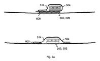
図5は、第1のコイル504−1と第2のコイル504−2を備える変形可能な電磁コイル構造体504を収容するボール500の実施形態を示す。二つのコイル504−1と504−2は、実質的に互いに直交する。それによって、コイルの“直交配置”は、二つ以上のコイルを配置することとして理解することができ、二つの異なるコイルの直線状に延出する導体パスは、それらの交差点で実質的に互いに対して垂直である。他の定義は、コイルの開口表面の表面垂線は、互いに対して実質的に垂直であることであってもよい。異なるコイル間又は異なるコイルに対して定義され且つ固定された交差点を持つために、交差点のための又は交差点において、ラグ、フィードスルーのような特別な固定要素を設けてもよい。図5において、同様に、他の二つのコイル504−1と504−2に直交するように配置される第3のコイルが存在してもよい。図5を見て分かるように、電磁コイル構造体504又はその個々のコイル504−1と504−2は、それぞれ、一つ以上の固定ストラップ514によってそれらの位置に絶対的に且つ相対的に固定され得る。それによって、固定ストラップ514は、コイル504−1と504−2を内部のボール空気袋506に及び/又はボール表皮502の内表面に固定できる。それによって、固定ストラップ514は、空気袋506の湾曲表面又は表皮502に対して横行の方向へのコイル504−1と504−2の変位を防止するように構成される。また、固定ストラップ514は、空気袋506又は表皮502の湾曲表面に沿ったコイル504−1と504−2それぞれの周方向又は長手方向への自由な動きを許容するように構成される。更に、コイル504−1とコイル504−2の相互の直交性は、固定ストラップ514の使用によって実質的に保つことができる。
FIG. 5 shows an embodiment of a
本発明の好適な実施形態では、固定ストラップ514は、表皮502と空気袋506との間に取り付けられる時に、コイル504−1と504−2を表皮パッチ508へ又はそれらの上に固定するために使用することができる。いくつかの実施形態では、ストラップ514は、弾性コイル基板又はバンド516と同じ幅dを有することができ、それによって、コイル504−1と504−2が横行の方向に動かない又はほんの僅かに動くことが可能である。なお、コイル構造体504に接続される一つ以上のチューニングキャパシタが見越されてもよい。
In a preferred embodiment of the present invention, a securing
図6aと図6bは、固定ストラップ514を使用した、ボール表皮502及び/又はボール空気袋506への電磁コイル504の固定に関する二つの実施形態を示す。それによって、固定ストラップ514を、接着剤600によってボール表皮502及び/又はボール空気袋506へ固定することができる。すなわち、固定ストラップ514を、ボール表皮パッチ508又はボール空気袋506の表面に接着することができる。図6aの上側に描かれている実施形態では、コイル構造体504は、固定ストラップ514によって完全に囲まれている。すなわち、固定ストラップ514は、コイル構造体504の周りにループを形成し、固定ストラップ514の全体のループ構造体は、ボール表皮502又はボール空気袋506に接着される。図6aの下側の実施形態では、固定ストラップ514は、コイル構造体504を覆うための一方の側の表皮として働く。この実施形態では、電磁コイル構造体504は、固定ストラップ514とボール表皮502又はボール空気袋506の表面との間に配される。それによって、固定ストラップ514を、コイル構造体504の両側(左側と右側)のボール表皮502又はボール空気袋506に接着することができる。
FIGS. 6 a and 6 b show two embodiments for securing the
図6bでは、コイル構造体604の一実施形態の横断面が概略的に示されている。コイル構造体604は、銅、銀又はアルミニウムのような導電性材料から作られる導電性巻線605を備える。コイル構造体604は、また、接着層609によってそれぞれ巻線605に固定又は取り付けることができる底部及び/又は頂部表皮基板607を備える。すなわち、いくつかの実施形態に従って、巻線605は、底部及び頂部表皮基板607間にラミネートされ得る。
In FIG. 6b, a cross section of one embodiment of the
電磁コイル構造体をゴール検出システムの特定の共振周波数、例えば、周波数125kHzへ調節する必要がある場合がある。このために、コイル構造体の浮遊容量は、十分であり得るが、追加の専用容量性素子が必要であるかもしれない。従って、いくつかの実施形態に従って、スポーツ用品の弾性変形可能なアイテム、例えば、ボールは、例えば、10kHzから150kHzの範囲における所定の周波数のための共振回路を形成するために、少なくとも一つの変形可能な電磁コイル構造体に連結される少なくとも一つの容量性素子を更に備えることができる。容量性素子やキャパシタは、しばしば、セラミック又は同様の材料から作られるので、誘導性コイル構造体よりも良好に保護されなければならない。このため、本発明のいくつかの実施形態は、少なくとも一つの容量性素子をボール表皮のパッチに一体化することを提案する。 It may be necessary to adjust the electromagnetic coil structure to a specific resonant frequency of the goal detection system, for example, a frequency of 125 kHz. For this, the stray capacitance of the coil structure may be sufficient, but additional dedicated capacitive elements may be required. Thus, according to some embodiments, the elastically deformable item of sports equipment, for example a ball, is at least one deformable, for example to form a resonant circuit for a predetermined frequency in the range of 10 kHz to 150 kHz. It may further include at least one capacitive element connected to the electromagnetic coil structure. Capacitive elements and capacitors are often made from ceramic or similar materials and must be better protected than inductive coil structures. For this reason, some embodiments of the present invention propose to integrate at least one capacitive element into a ball skin patch.
図7は、チューニングキャパシタ700の固定のための一実施形態を示す。ゴム、発泡材、又は表皮パッチ材料と同様な材料のようなフレキシブル材料から作ることができる、ケースリング又は保護リング720は、ボール表皮パッチ708の内表面に取り付けることができる。ケースリング720の半径方向延出部は、十分に高く、ケースリング720は、十分に大きな直径を有する孔722を有することができ、それによって、コイル構造体の共振チューニング(調節)のための少なくとも一つの受動キャパシタ部品700がその孔722内に配されることができる。キャパシタ700は、キャパシタ700の対応するコネクタにはんだ付け可能な接続ワイヤ724を介してコイル構造体及び/又は他の電子部品に接続することができる。孔722内にキャパシタ700を置いた後、孔722に、キャパシタ700と接続ワイヤ724をケースリング720内に固定するために、接着剤又は他の成形材を充填することができる。図7の下の横断面図は、キャパシタ700を収容するケースリング720がボール表皮702とボール空気袋706との間に如何に嵌るかを描いている。変形可能な電磁コイル構造体が、二つ以上の電磁コイルを備える場合、複数の電磁コイルそれぞれは、それぞれ、少なくとも一つのキャパシタによって予め定義された共振周波数又は共振周波数範囲に別々に調整され得る。
FIG. 7 illustrates one embodiment for fixing the
記述及び図面は、単に本発明の原理を描いている。従って、当業者は、本明細書では明示的に記述されていない、又は示されていないが、本発明の原理を具体化し、本発明の精神と範囲内に含まれる様々な構成を考案できることを理解する。実施形態をゴール検出システムに関して描いたが、代替の実施形態もまた、防犯デバイス(例えば、フレキシブルコイルの商品中への又はその上への挿入)、例えば、アイスホッケーのような更なるスポーツに関連してもよい。また、実施形態は、例えば、フレキシブル且つ平らなコイルを靴等に一体化することによって、安全エリアを調査するために有用であり得る。 The description and drawings merely depict the principles of the invention. Accordingly, those skilled in the art will recognize that the principles of the invention may be embodied and various constructions falling within the spirit and scope of the invention may be devised which are not explicitly described or shown herein. to understand. Although the embodiments have been described with respect to a goal detection system, alternative embodiments are also associated with further sports such as security devices (eg, insertion of flexible coils into or on products), eg, ice hockey May be. Embodiments can also be useful for investigating safety areas, for example, by integrating a flexible and flat coil into a shoe or the like.
更に、本明細書で引用された全ての例は、主に、発明の原理及び発明者によって与えられた概念を読者が理解するのを助け、その技術を促進するための教育目的のためのみであるよう明確に意図しており、且つそのような具体的に引用された例及び条件へ制限しないように解釈される。更に、発明の原理、態様及び実施形態、並びにそれらの具体的な例を本明細書で引用する全ての記述は、それらの等価物を包含することを意図している。 Furthermore, all examples cited herein are primarily for educational purposes only to help the reader understand the principles of the invention and the concepts given by the inventor and to promote the technology. It is expressly intended to be interpreted and is not to be limited to such specifically cited examples and conditions. Furthermore, all descriptions of the principles, aspects and embodiments of the invention, as well as specific examples thereof, cited herein are intended to encompass their equivalents.
更に、以下の請求項は、これによって、詳細な説明に組み込まれており、そこでは、各請求項は、個別の実施形態として自立することができる。なお、各請求項は、個別の実施形態として自立することができると共に、従属請求項は、特許請求の範囲において、一つ以上の他の請求項との特定の組合せを指すが、他の実施形態は、各他の従属請求項の主題との従属請求項の組合せを含んでいてもよい。特定の組合せが意図されていないことが述べられない限り、そのような組合せが、本明細書では、提案される。更に、一つの請求項が他の独立請求項に直接的には従属しないとしても、その請求項は、その他の独立請求項の特徴を含むことが意図される。 Furthermore, the following claims are hereby incorporated into the detailed description, wherein each claim can stand on its own as a separate embodiment. Note that each claim can stand on its own as a separate embodiment, and a dependent claim refers in a claim to a particular combination with one or more other claims, but other implementations. The form may include a combination of the dependent claims with the subject matter of each other dependent claim. Such combinations are proposed herein unless it is stated that a particular combination is not intended. Moreover, even if one claim is not directly dependent on another independent claim, that claim is intended to include the features of the other independent claim.
なお、更に、本明細書に又は特許請求の範囲に開示される方法は、これらの方法それぞれのステップの各々を実行するための手段を有するデバイスによって実行され得る。 Still further, the methods disclosed herein or in the claims can be performed by a device having means for performing each of the steps of each of these methods.
更に、当然のことながら、本明細書に又は特許請求の範囲に開示される複数のステップ又は機能の開示は、指定の順序内であると解釈できない。従って、複数のステップ又は機能の開示は、そのようなステップ又は機能が技術的な理由で相互に交換できない場合を除いて、これらのステップ又は機能を指定の順序に制限しない。更に、いくつかの実施形態では、単一のステップは、複数のサブステップを含んでいても、それらに細分割されてもよい。このようなサブステップは、明示的に排除されない限り、含まれても、この単一のステップの開示の一部であってもよい。 Furthermore, it should be understood that the disclosure of steps or functions disclosed herein or in the claims cannot be construed in a specified order. Thus, disclosure of multiple steps or functions does not limit these steps or functions to a specified order unless such steps or functions are not interchangeable for technical reasons. Further, in some embodiments, a single step may include multiple substeps or be subdivided into them. Such substeps may be included or part of the disclosure of this single step, unless expressly excluded.
100: ボール
102: ボール表皮
104: ループアンテナ
106: 湾曲表面
200: ボール
202: ボール表皮
204: ループアンテナ
206: 湾曲表面
204: 電磁コイル構造体
216: 基板
250: ボール
252: ボール表皮
254: コイル
256: ボール空気袋
300: ボール
302: ボール表皮
304: 電磁コイル構造体
306: ボール空気袋
310: 継ぎ目
500: ボール
502: ボール表皮
504: 電磁コイル構造体
506: ボール空気袋
514: 固定ストラップ
516: 基板
700: キャパシタ
702: ボール表皮
708: パッチ
100: Ball 102: Ball skin 104: Loop antenna 106: Curved surface 200: Ball 202: Ball skin 204: Loop antenna 206: Curved surface 204: Electromagnetic coil structure 216: Substrate 250: Ball 252: Ball skin 254: Coil 256 : Ball air bag 300: Ball 302: Ball skin 304: Electromagnetic coil structure 306: Ball air bag 310: Seam 500: Ball 502: Ball skin 504: Electromagnetic coil structure 506: Ball air bag 514: Fixed strap 516: Substrate 700: Capacitor 702: Ball skin 708: Patch
Claims (16)
前記スポーツ用品のアイテム内で湾曲表面(102;106;202;206;252;256;302;306;502;506)の周りに配置される、少なくとも1ターンの弾性導電体を備える少なくとも一つの変形可能なループアンテナ(104;204;254;304;504)を備え、
前記少なくとも一つの変形可能なループアンテナは、前記スポーツ用品のアイテムの最大弾性変形に対応する伸長余裕部を有する、スポーツ用品のアイテム(100;200;250;300;500)。 An elastically deformable item of sports equipment (100; 200; 250; 300; 500),
The sports equipment of the curved surface in the item (102; 106; 202; 206; 252; 256; 302; 306; 502; 506) is disposed around a least one comprising an elastic conductor of at least one turn Two deformable loop antennas (104; 204; 254; 304; 504);
The sports equipment item (100; 200; 250; 300; 500), wherein the at least one deformable loop antenna has an extension margin corresponding to a maximum elastic deformation of the sports equipment item.
前記スポーツ用品のアイテム内で湾曲表面(102;106;202;206;252;256;302;306;502;506)の周りに、少なくとも1ターンの弾性導電体を備える少なくとも一つの変形可能なループアンテナ(104;204;254;304;504)を配置するステップを備え、それによって、前記少なくとも一つの変形可能なループアンテナは、前記スポーツ用品のアイテムの最大弾性変形に対応する伸長余裕部を有する、方法。 A method for manufacturing an elastically deformable item (100; 200; 250; 300; 500) of a sports equipment, comprising:
The sports equipment of the curved surface in the item (102; 106; 202; 206; 252; 256; 302; 306; 502; 506) around the, least one deformable with an elastic conductor of at least one turn A loop antenna (104; 204; 254; 304; 504), whereby the at least one deformable loop antenna has an extension margin corresponding to a maximum elastic deformation of the item of sports equipment Having a method.
Applications Claiming Priority (3)
| Application Number | Priority Date | Filing Date | Title |
|---|---|---|---|
| US201261675984P | 2012-07-26 | 2012-07-26 | |
| US61/675,984 | 2012-07-26 | ||
| PCT/EP2012/073731 WO2014015917A1 (en) | 2012-07-26 | 2012-11-27 | Elastically deformable item of sports equipment comprising a deformable electromagnetic coil structure |
Publications (2)
| Publication Number | Publication Date |
|---|---|
| JP2015530891A JP2015530891A (en) | 2015-10-29 |
| JP6014255B2 true JP6014255B2 (en) | 2016-10-25 |
Family
ID=47557022
Family Applications (1)
| Application Number | Title | Priority Date | Filing Date |
|---|---|---|---|
| JP2015523430A Active JP6014255B2 (en) | 2012-07-26 | 2012-11-27 | An elastically deformable item of sports equipment having a deformable electromagnetic coil structure |
Country Status (7)
| Country | Link |
|---|---|
| US (1) | US9735472B2 (en) |
| EP (2) | EP3112002B1 (en) |
| JP (1) | JP6014255B2 (en) |
| CN (1) | CN104507542B (en) |
| DK (1) | DK3112002T3 (en) |
| ES (2) | ES2604342T3 (en) |
| WO (1) | WO2014015917A1 (en) |
Families Citing this family (11)
| Publication number | Priority date | Publication date | Assignee | Title |
|---|---|---|---|---|
| DE102013100216B4 (en) * | 2012-12-13 | 2014-12-24 | Fraunhofer-Gesellschaft zur Förderung der angewandten Forschung e.V. | ELASTICALLY DEFORMABLE SPORTS EQUIPMENT WITH A DEFORMABLE ELECTROMAGNETIC COIL STRUCTURE |
| JP6656223B2 (en) | 2014-07-31 | 2020-03-04 | スリーエム イノベイティブ プロパティズ カンパニー | RFID tag on flexible board |
| US10229353B2 (en) | 2014-07-31 | 2019-03-12 | 3M Innovative Properties Company | RFID tag on stretchable substrate |
| US9360894B1 (en) * | 2015-02-12 | 2016-06-07 | Htc Corporation | Water-resistant electronic device and water resistant key module |
| JP6598533B2 (en) * | 2015-06-30 | 2019-10-30 | ブリヂストンスポーツ株式会社 | Golf ball with built-in IC chip |
| CN106953426B (en) * | 2017-04-21 | 2020-09-11 | 天津工业大学 | Novel wireless power transmission omnidirectional three-dimensional transmitting coil device |
| US10675526B2 (en) | 2017-05-01 | 2020-06-09 | Intel Corporation | Sports apparatus and methods including tracking additives |
| WO2022053741A1 (en) * | 2020-09-09 | 2022-03-17 | Wisehockey Oy | A ball and a method for manufacturing the same |
| KR102461519B1 (en) * | 2020-12-17 | 2022-11-02 | 주식회사 바른바이오 | Elastic exercise equipment and elastic exercise set |
| CN113350753A (en) * | 2021-05-07 | 2021-09-07 | 焦作大学 | Basketball with shooting counting function |
| CN113644414B (en) * | 2021-07-08 | 2022-05-06 | 大连理工大学 | Antenna device, method for manufacturing the same, and communication device |
Family Cites Families (16)
| Publication number | Priority date | Publication date | Assignee | Title |
|---|---|---|---|---|
| GB1370331A (en) | 1971-03-03 | 1974-10-16 | L Supran | Sports ball having an electrically conducting surface |
| US3774194A (en) | 1972-01-12 | 1973-11-20 | P Jokay | Game court boundary indicator system |
| US4299384A (en) | 1975-04-23 | 1981-11-10 | Auken John A Van | Electrically conductive game ball |
| US4754285A (en) * | 1987-05-01 | 1988-06-28 | Timex Corporation | Expansion band antenna for a wristwatch application |
| JPH037852U (en) | 1989-06-12 | 1991-01-25 | ||
| DE4327433A1 (en) | 1993-08-14 | 1995-02-16 | Roland Prof Dr Phil Naul | Sensor-based hit (strike) surface for sport |
| JP2687864B2 (en) | 1993-12-29 | 1997-12-08 | 日本電気株式会社 | Flying object search system |
| JP2603808B2 (en) | 1994-08-26 | 1997-04-23 | カワサキコーポレーション株式会社 | Baseball ball and method of manufacturing the same |
| GB2383470B (en) | 2001-11-12 | 2004-04-28 | Transense Technologies Plc | Self contained radio apparatus for transmission of data |
| US7691009B2 (en) | 2003-09-26 | 2010-04-06 | Radar Golf, Inc. | Apparatuses and methods relating to findable balls |
| US20050288134A1 (en) * | 2004-06-25 | 2005-12-29 | Smith David K | Sensiball |
| KR100879759B1 (en) | 2007-08-24 | 2009-01-21 | 임성규 | Ball mark for golf |
| US8538556B2 (en) | 2008-04-01 | 2013-09-17 | Pacesetter, Inc. | Enhanced implantable antenna method |
| DE102008058943B3 (en) * | 2008-11-25 | 2010-05-12 | Adidas International Marketing B.V. | Bubble for a ball |
| US20100184564A1 (en) * | 2008-12-05 | 2010-07-22 | Nike, Inc. | Athletic Performance Monitoring Systems and Methods in a Team Sports Environment |
| FR2970420B1 (en) | 2011-01-14 | 2013-11-08 | Crazy Nets | NET FOR SPORTS EQUIPMENT AND SPORTS EQUIPMENT FOR BALL GAMES OR THE LIKE COMPRISING THE SAME |
-
2012
- 2012-11-27 ES ES12813776.7T patent/ES2604342T3/en active Active
- 2012-11-27 CN CN201280074907.1A patent/CN104507542B/en active Active
- 2012-11-27 EP EP16180860.5A patent/EP3112002B1/en active Active
- 2012-11-27 WO PCT/EP2012/073731 patent/WO2014015917A1/en active Application Filing
- 2012-11-27 JP JP2015523430A patent/JP6014255B2/en active Active
- 2012-11-27 ES ES16180860.5T patent/ES2666227T3/en active Active
- 2012-11-27 EP EP12813776.7A patent/EP2877252B1/en active Active
- 2012-11-27 US US14/415,659 patent/US9735472B2/en active Active
- 2012-11-27 DK DK16180860.5T patent/DK3112002T3/en active
Also Published As
| Publication number | Publication date |
|---|---|
| JP2015530891A (en) | 2015-10-29 |
| EP3112002B1 (en) | 2018-01-17 |
| EP3112002A1 (en) | 2017-01-04 |
| CN104507542A (en) | 2015-04-08 |
| EP2877252A1 (en) | 2015-06-03 |
| EP2877252B1 (en) | 2016-09-07 |
| WO2014015917A1 (en) | 2014-01-30 |
| US20150180127A1 (en) | 2015-06-25 |
| ES2604342T3 (en) | 2017-03-06 |
| CN104507542B (en) | 2017-06-16 |
| ES2666227T3 (en) | 2018-05-03 |
| DK3112002T3 (en) | 2018-05-07 |
| US9735472B2 (en) | 2017-08-15 |
Similar Documents
| Publication | Publication Date | Title |
|---|---|---|
| JP6014255B2 (en) | An elastically deformable item of sports equipment having a deformable electromagnetic coil structure | |
| US9586099B2 (en) | Tracking balls in sports | |
| AU2009306662B2 (en) | Oval ball, in particular rugby ball or football having a transmitter | |
| US11219801B2 (en) | Golf ball with RFID inlay between a split core | |
| US9539471B2 (en) | Golf ball with encapsulated RFID chip | |
| US9370694B2 (en) | Golf ball with RFID inlay in a molded impression | |
| JP5079776B2 (en) | Inner bag | |
| EP2868169B1 (en) | Concept for assembling an electromagnetic coil using a flexible printed circuit board | |
| US9889343B2 (en) | Elastically deformable item of sports equipment comprising a deformable electromagnetic coil structure | |
| WO2013149681A1 (en) | Ball for a sports game with a plurality of loop antennas | |
| TWM578481U (en) | Magnetic resonance type wireless charging intelligent ball |
Legal Events
| Date | Code | Title | Description |
|---|---|---|---|
| A977 | Report on retrieval |
Free format text: JAPANESE INTERMEDIATE CODE: A971007 Effective date: 20160413 |
|
| A131 | Notification of reasons for refusal |
Free format text: JAPANESE INTERMEDIATE CODE: A131 Effective date: 20160426 |
|
| A521 | Request for written amendment filed |
Free format text: JAPANESE INTERMEDIATE CODE: A523 Effective date: 20160726 |
|
| TRDD | Decision of grant or rejection written | ||
| A01 | Written decision to grant a patent or to grant a registration (utility model) |
Free format text: JAPANESE INTERMEDIATE CODE: A01 Effective date: 20160830 |
|
| A61 | First payment of annual fees (during grant procedure) |
Free format text: JAPANESE INTERMEDIATE CODE: A61 Effective date: 20160923 |
|
| R150 | Certificate of patent or registration of utility model |
Ref document number: 6014255 Country of ref document: JP Free format text: JAPANESE INTERMEDIATE CODE: R150 |
|
| R250 | Receipt of annual fees |
Free format text: JAPANESE INTERMEDIATE CODE: R250 |
|
| R250 | Receipt of annual fees |
Free format text: JAPANESE INTERMEDIATE CODE: R250 |
|
| R250 | Receipt of annual fees |
Free format text: JAPANESE INTERMEDIATE CODE: R250 |
|
| R250 | Receipt of annual fees |
Free format text: JAPANESE INTERMEDIATE CODE: R250 |
|
| R250 | Receipt of annual fees |
Free format text: JAPANESE INTERMEDIATE CODE: R250 |