JP6012230B2 - Edge direction determination device, control method of edge direction determination device, and image processing device - Google Patents
Edge direction determination device, control method of edge direction determination device, and image processing device Download PDFInfo
- Publication number
- JP6012230B2 JP6012230B2 JP2012087468A JP2012087468A JP6012230B2 JP 6012230 B2 JP6012230 B2 JP 6012230B2 JP 2012087468 A JP2012087468 A JP 2012087468A JP 2012087468 A JP2012087468 A JP 2012087468A JP 6012230 B2 JP6012230 B2 JP 6012230B2
- Authority
- JP
- Japan
- Prior art keywords
- block
- pixel
- value
- blocks
- size
- Prior art date
- Legal status (The legal status is an assumption and is not a legal conclusion. Google has not performed a legal analysis and makes no representation as to the accuracy of the status listed.)
- Expired - Fee Related
Links
Images


Description
本発明は、エッジ方向判定装置、エッジ方向判定装置の制御方法、及び、画像処理装置に関する。 The present invention relates to an edge direction determination device, a control method for an edge direction determination device, and an image processing device.
インターレース画像信号を補間によりプログレッシブ画像信号に変換する方法として、動き適応型IP(インターレース−プログレッシブ)変換と呼ばれる方法がある。これは、補間画素の生成位置での画像の動き(動き情報)を検出し、その動き情報に応じて、補間画素としてフィールド内補間画素を生成するか、フィールド間補間画素を生成するかを適応的に切り換える方法である。 As a method for converting an interlaced image signal into a progressive image signal by interpolation, there is a method called motion adaptive IP (interlace-progressive) conversion. This detects image motion (motion information) at the interpolation pixel generation position, and adapts whether to generate intra-field interpolation pixels or inter-field interpolation pixels according to the motion information. It is a method of switching automatically.
動き適応型IP変換では、「動きあり」と判定された位置に対して、同一フィールド内において該位置の垂直方向に隣接する画素を用いて補間画素が生成される。そのため、斜め方向のエッジ部分(斜めエッジ部分)では、ジャギーと呼ばれるギザギザが発生することとなり、画像品位(画質)が著しく劣化してしまう。 In the motion-adaptive IP conversion, an interpolation pixel is generated using a pixel adjacent to the position in the same field in the same field for a position determined to be “with motion”. Therefore, a jagged edge is generated at an oblique edge portion (an oblique edge portion), and the image quality (image quality) is significantly deteriorated.
ジャギーの発生を抑制する技術として、入力されたインターレース画像信号の画素情報からエッジの方向を判定し、エッジの方向に応じた画素を用いて補間画素を生成する方法が提案されている。
そのような方法は、例えば、特許文献1に開示されている。
具体的には、特許文献1には、予め決められた斜め方向のリファレンスパターンと入力画像信号とのパターンマッチングにより、エッジの方向を判定することが開示されている。また、リファレンスパターンのサイズ(ブロックサイズ)を大きくすることで、より角度の浅いエッジの方向が判定可能となることが開示されている。
As a technique for suppressing the occurrence of jaggy, a method has been proposed in which the direction of an edge is determined from pixel information of an input interlaced image signal, and an interpolation pixel is generated using a pixel corresponding to the direction of the edge.
Such a method is disclosed in
Specifically,
しかしながら、上述した従来の技術では、エッジの方向を精度良く判定することができず、エッジの方向の誤判定が発生してしまうことがある。例えば、ブロックサイズが大きい場合には、角度が深い斜めエッジ部分において、斜めエッジ部分以外の画像がパターンマッチングに大きな影響を与えてしまうことがある。そのため、大きなブロックサイズでのパターンマッチングによりエッジの方向を判定する構成では、角度の深いエッジの方向を精度良く判定することができない。また逆に、小さなブロックサイズでのパターンマッチングによりエッジの方向を判定する構成では、角度の浅いエッジの方向を精度良く判定することができない。エッジの方向の誤判定があると、エッジの方向の判定結果に基づく画像処理を行った際に、画質が劣化してしまう。例えば、上述したジャギー等の視覚的な妨害のある画像が生成されてしまう。 However, in the conventional technique described above, the edge direction cannot be accurately determined, and an erroneous determination of the edge direction may occur. For example, when the block size is large, an image other than the oblique edge portion may greatly affect pattern matching in the oblique edge portion having a deep angle. Therefore, in the configuration in which the edge direction is determined by pattern matching with a large block size, the edge direction having a deep angle cannot be accurately determined. Conversely, in the configuration in which the edge direction is determined by pattern matching with a small block size, the direction of the edge having a shallow angle cannot be accurately determined. If there is an erroneous determination of the edge direction, the image quality deteriorates when image processing based on the determination result of the edge direction is performed. For example, an image having visual disturbance such as the above-described jaggy is generated.
本発明は、エッジの方向を精度良く判定することのできる技術を提供することを目的とする。 An object of the present invention is to provide a technique capable of accurately determining the direction of an edge.
本発明の第1の態様は、
画像の注目点におけるエッジの方向を判定するエッジ方向判定装置であって、
エッジの方向の候補である複数の方向のそれぞれについて、注目点を通るその方向の直線上に、同じサイズの領域であるn個(nは2以上の整数)のブロックを設定する設定手段と、
前記複数の方向のそれぞれについて、前記設定手段で設定されたn個のブロック間の画像の類似度を算出し、類似度が最も高い方向を、前記注目点におけるエッジの方向として判定する判定手段と、
を有し、
前記設定手段は、エッジの方向の候補である前記方向毎に、
その方向に対して設定するn個のブロックのうちの少なくとも1つのブロックについて、そのブロックの設定位置である前記直線上の位置における、所定方向の位置の変化に対する画素値の変化の勾配を算出し、
勾配が大きいときよりも、勾配が小さいときのほうが、前記所定方向の長さが長くなるように、前記設定するn個のブロックのサイズを制御する
ことを特徴とする。
The first aspect of the present invention is:
An edge direction determination device that determines the direction of an edge at a point of interest in an image,
For each of a plurality of directions that are edge direction candidates, setting means for setting n (n is an integer of 2 or more) blocks of the same size on a straight line in that direction passing through the point of interest;
Determination means for calculating the image similarity between the n blocks set by the setting means for each of the plurality of directions and determining the direction having the highest similarity as the edge direction at the point of interest; ,
Have
For each of the directions that are candidates for edge directions, the setting means
For at least one of the n blocks set for that direction, the gradient of the change in pixel value with respect to the change in the position in the predetermined direction at the position on the straight line, which is the set position of that block, is calculated. ,
The size of the n blocks to be set is controlled so that the length in the predetermined direction becomes longer when the gradient is small than when the gradient is large .
本発明の第2の態様は、
インターレース画像信号を補間によりプログレッシブ画像信号に変換する画像処理装置であって、
上記エッジ方向判定装置と、
前記エッジ方向判定装置で判定されたエッジの方向に基づいて、フィールド内補間による補間画素を生成する補間画素生成手段と、
を有することを特徴とする。
The second aspect of the present invention is:
An image processing apparatus that converts an interlaced image signal into a progressive image signal by interpolation,
The edge direction determination device;
Interpolation pixel generation means for generating an interpolation pixel by intra-field interpolation based on the edge direction determined by the edge direction determination device;
It is characterized by having.
本発明の第3の態様は、
画像の注目点におけるエッジの方向を判定するエッジ方向判定装置の制御方法であって、
エッジの方向の候補である複数の方向のそれぞれについて、注目点を通るその方向の直線上に、同じサイズの領域であるn個(nは2以上の整数)のブロックを設定する設定ステップと、
前記複数の方向のそれぞれについて、前記設定ステップで設定されたn個のブロック間の画像の類似度を算出し、類似度が最も高い方向を、前記注目点におけるエッジの方向として判定する判定ステップと、
を有し、
前記設定ステップでは、エッジの方向の候補である前記方向毎に、
その方向に対して設定するn個のブロックのうちの少なくとも1つのブロックについて、そのブロックの設定位置である前記直線上の位置における、所定方向の位置の変化に対する画素値の変化の勾配が算出され、
勾配が大きいときよりも、勾配が小さいときのほうが、前記所定方向の長さが長くなるように、前記設定するn個のブロックのサイズが制御される
ことを特徴とする。
The third aspect of the present invention is:
A control method of an edge direction determination device that determines the direction of an edge at a point of interest in an image,
A setting step of setting n (n is an integer of 2 or more) blocks of the same size on a straight line passing through the point of interest for each of a plurality of directions that are edge direction candidates;
A determination step of calculating an image similarity between the n blocks set in the setting step for each of the plurality of directions, and determining a direction having the highest similarity as an edge direction at the point of interest; ,
Have
In the setting step, for each direction that is a candidate for an edge direction,
For at least one of the n blocks set for that direction, the gradient of the change in pixel value with respect to the change in position in the predetermined direction at the position on the straight line, which is the set position of that block, is calculated. ,
The size of the n blocks to be set is controlled so that the length in the predetermined direction becomes longer when the gradient is small than when the gradient is large .
本発明によれば、エッジの方向を精度良く判定することができる。 According to the present invention, the edge direction can be determined with high accuracy.
<実施例1>
以下、本発明の実施例1に係るエッジ方向判定装置、エッジ方向判定装置の制御方法、及び、画像処理装置について、図面を用いて説明する。本実施例では、エッジ方向判定装置を有する画像処理装置が、IP変換(具体的には動き適応型IP変換)を行う画像処理装置である場合の例について説明するが、本発明のエッジ方向判定装置(及びその制御方法)は、画像の注目点におけるエッジの方向を判定するいかなる装置にも適用することができる。IP変換は、インターレース画像信号を補間によりプログレッシブ画像信号に変
換する処理である。動き適応型IP変換は、補間画素の生成位置での画像の動き(動き情報)を検出し、その動き情報に応じて、補間画素としてフィールド内補間画素を生成するか、フィールド間補間画素を生成するかを適応的に切り換えるIP変換である。
<Example 1>
Hereinafter, an edge direction determination apparatus, an edge direction determination apparatus control method, and an image processing apparatus according to
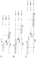
図1は、本実施例に係る画像処理装置の構成を示すブロック図である。
図1において、フィールドメモリ100,101はフィールド単位で装置に入力されるインターレース画像信号を蓄積し、該インターレース画像信号を1フィールド分だけ遅延させて出力する。即ち、画像処理装置にN番目のフィールド(Nフィールド)の画像信号FD0が入力された時に、フィールドメモリ100からは、N−1番目のフィールド(N−1フィールド)の画像信号FD1が出力される。フィールドメモリ101からは、N−2番目のフィールド(N−2フィールド)の画像信号FD2が出力される。本実施例では、N−1フィールドの画像信号FD1に対して補間画素が生成される。
FIG. 1 is a block diagram illustrating the configuration of the image processing apparatus according to the present embodiment.
In FIG. 1,
動き検出部102は、補間画素の生成位置での画像の動きを検出する。本実施例では、動き検出部102は、Nフィールド信号FD0及びN−2フィールド信号FD2の2つのフィールドの画像信号を用いて、補間画素の生成位置での画像の動き(動き情報MV)を検出する。具体的には、動き検出部102は、画素毎に、2つのフィールド間の画素値の差分値を閾値と比較することにより、動きの有無を判定する。差分値が閾値以上の場合は、画像の動きがある(MV=1(動き))と判定され、差分値が閾値未満の場合には、画像の動きがない(MV=0(静止))と判定される。そして、この判定結果(画素毎のMVの値)が動き情報として補間画素生成部105へ出力される。なお、動きの検出方法はこれに限らない。例えば、ブロックマッチングにより動きが検出されてもよい。
The
斜め検出部103は、補間画素の生成位置(注目点)におけるエッジの方向を判定する(エッジ方向判定装置)。具体的には、斜め検出部103は、補間画素の生成位置がエッジ部分か否かを判定する。そして、斜め検出部103は、補間画素の生成位置がエッジ部分であると判定した場合に、該エッジの方向を表す情報をフィールド内補間画素生成部104へ出力する。本実施例では、エッジの方向を表す情報として、当該方向の水平方向に対する傾斜角度を表す角度情報ANGLEが出力される。本実施例では、角度情報ANGLEは、−15〜+15の値を取り得るものとする。斜め検出部103が本実施例に係るエッジ方向判定装置に相当する。斜め検出部103の動作の詳細については、後述する。
The
フィールド内補間画素生成部104は、角度情報ANGLEに基づいて、フィールド内補間による補間画素(フィールド内補間画素)を生成して出力する。具体的には、フィールド内補間画素生成部104は、フィールド内補間画素の画素値ID1を算出し、出力する。フィールド内補間画素は、画像の動きのある位置に生成するのに適した補間画素であり、補間画素の生成の対象となるN−1フィールド信号FD1の画素値を用いて生成される補間画素である。
The intra-field interpolation
フィールド内補間画素生成部104は、例えば、図2に示すような構成を有する。
フィールド内補間画素生成部104に入力されたN−1フィールド信号FD1は、ラインメモリ200と選択部A201に入力される。
ラインメモリ200は、入力されたN−1フィールド信号FD1を1H(1水平走査期間)だけ遅延させ、当該遅延させた信号を1H遅延信号LD1として選択部B202に出力する。
選択部A201は、補間画素の生成位置毎に、N−1フィールド信号FD1(補間画素の生成位置の1つ下のラインの画像信号)から、角度情報ANGLEに応じた画素を選択し、その画素の画素値S1を出力する。
選択部B202は、補間画素の生成位置毎に、1H遅延信号LD1(補間画素の生成位置の1つ上のラインの画像信号)から、角度情報ANGLEに応じた画素を選択し、その
画素の画素値S2を出力する。
The intra-field interpolation
The N−1 field signal FD1 input to the intra-field interpolation
The
For each interpolation pixel generation position, the selection unit A201 selects a pixel corresponding to the angle information ANGLE from the N-1 field signal FD1 (the image signal of the line immediately below the interpolation pixel generation position), and the pixel The pixel value S1 is output.
For each interpolation pixel generation position, the selection unit B202 selects a pixel corresponding to the angle information ANGLE from the 1H delay signal LD1 (the image signal of the line one line above the interpolation pixel generation position), and the pixel of the pixel The value S2 is output.
選択部A201及び選択部B202における画素の選択方法について、図3(A)を用いて説明する。
図3(A)において、画素u(x)は、補間画素の生成位置Hの1つ上のライン上の画素であり、図2における1H遅延信号LD1で表される画素である。画素d(x)は、補間画素の生成位置Hの1つ下のライン上の画素であり、図2におけるN−1フィールド信号FD1で表される画素である。xは、補間画素の生成位置に対する画素u(x),d(x)の位置の水平方向のずれ量(補間画素の生成位置を基準とする画素u(x),d(x)の水平方向の位置を示す値)である。xの値が負の値である場合には、画素u(x),d(x)の水平方向の位置は、補間画素の生成位置に対して左側へ|x|画素ずれた位置となる。xの値が正の値である場合には、画素u(x),d(x)の水平方向の位置は、補間画素の生成位置に対して右側へ|x|画素ずれた位置となる。
A pixel selection method in the selection unit A201 and the selection unit B202 will be described with reference to FIG.
In FIG. 3A, a pixel u (x) is a pixel on a line immediately above the interpolation pixel generation position H, and is a pixel represented by the 1H delay signal LD1 in FIG. The pixel d (x) is a pixel on the line immediately below the interpolation pixel generation position H, and is a pixel represented by the N-1 field signal FD1 in FIG. x is a horizontal shift amount of the positions of the pixels u (x) and d (x) with respect to the generation position of the interpolation pixel (the horizontal direction of the pixels u (x) and d (x) based on the generation position of the interpolation pixel). Is a value indicating the position). When the value of x is a negative value, the horizontal positions of the pixels u (x) and d (x) are shifted by | x | pixels to the left with respect to the interpolation pixel generation position. When the value of x is a positive value, the horizontal positions of the pixels u (x) and d (x) are shifted by | x | pixels to the right from the interpolation pixel generation position.
本実施例では、斜め検出部103は、角度情報ANGLEとして、上述したxの値を出力する。また、斜め検出部103は、補間画素の生成位置がエッジ部分でない場合には、角度情報ANGLE=0を出力する。
角度情報ANGLE=+A(Aは自然数)の場合は、選択部A201でu(+A)が選択され、選択部B202でd(−A)が選択される。図3(A)は、補間画素の生成位置Hに対する角度情報ANGLEが+3の場合の例である。この場合、選択部A201でu(+3)が選択され、選択部B202でd(−3)が選択される。また、角度情報ANGLE=0の場合には、図3(B)に示すように、選択部A201でu(0)が選択され、選択部B202でd(0)が選択される。
In the present embodiment, the
When the angle information ANGLE = + A (A is a natural number), u (+ A) is selected by the selection unit A201, and d (−A) is selected by the selection unit B202. FIG. 3A shows an example in which the angle information ANGLE for the interpolation pixel generation position H is +3. In this case, u (+3) is selected by the selection unit A201, and d (-3) is selected by the selection unit B202. When the angle information ANGLE = 0, as shown in FIG. 3B, u (0) is selected by the selection unit A201, and d (0) is selected by the selection unit B202.
加算器203は、選択部A201から出力された画素値S1と選択部B202から出力された画素値S2とを足し合わせることにより画素値S3を算出し、乗算器204へ出力する。
乗算器204は、画素値S3を1/2倍し、その結果(画素値S3を1/2倍した値)を、フィールド内補間画素の画素値ID1(フィールド内補間値)として出力する。
これにより、N−1フィールド信号FD1において、エッジ部分の補間画素の画素値として、そのエッジの方向に隣接する2画素の画素値の平均値を得ることができる。また、エッジ部分以外の位置の補間画素の画素値として、垂直方向に隣接する2画素の画素値の平均値を得ることができる。
The
The
Thereby, in the N-1 field signal FD1, the average value of the pixel values of two pixels adjacent in the direction of the edge can be obtained as the pixel value of the interpolation pixel of the edge portion. Moreover, the average value of the pixel values of two pixels adjacent in the vertical direction can be obtained as the pixel value of the interpolation pixel at a position other than the edge portion.
補間画素生成部105は、補間画素の生成位置毎に、動き情報MVに応じて補間方法を切り換え、補間画素を生成する(補間画素の画素値ID2を決定する)。即ち、補間画素生成部105は、動き適応型IP変換により補間画素を生成する。具体的には、補間画素の生成位置において画像の動きがない場合(MV=0である場合)には、補間画素生成部105は、該生成位置に対し、N−2フィールド信号FD2の画素値を画素値ID2として用いて、補間画素(フィールド間補間画素)を生成する。画像の動きがある場合(MV=1である場合)には、補間画素生成部105は、該生成位置に対し、フィールド内補間値ID1を画素値ID2として用いて、補間画素(フィールド内補間画素)を生成する。そして、補間画素生成部105は、各補間画素の画素値ID2を倍速変換部106へ出力する。なお、フィールド間補間画素は、画像の動きのない位置に生成するのに適した補間画素であって、N−2フィールド信号の画素値(補間画素の生成位置と同じ位置の画素値)と同じ画素値を有する補間画素である。
The interpolation
倍速変換部106は、各補間画素の画素値ID2と、N−1フィールド信号FD1とを合成してプログレッシブ画像信号(プログレッシブ画像の1フレームの画像信号)として出力する。具体的には、倍速変換部106は、N−1フィールド信号FD1と、各補間画
素の画素値ID2とを、インターレース画像信号が入力される速度の2倍の速度でライン毎に交互に読み出す。これにより、N−1フィールド信号FD1のオリジナルライン(N−1フィールドのインターレース画像を構成する画素からなるライン)のデータと、画素値ID2を有する補間画素からなるライン(補間ライン)のデータとがライン毎に交互に読み出される。そして、倍速変換部106は、データを読み出す度に、読み出したデータをプログレッシブ画像信号(プログレッシブ画像の1ラインのデータ)として出力する。
The double
次に、斜め検出部103の構成について説明する。図4は、本実施例に係る斜め検出部103の内部構成を示すブロック図である。図4に示すように、本実施例に係る斜め検出部103は、ラインメモリ300、マッチング領域算出部D301、マッチング領域算出部U302、制御部303、切り出し位置決定部304、マッチング角度決定部305、ブロックサイズ決定部306、ブロックマッチング部307、マッチング角度算出部308などを備える。
Next, the configuration of the
ラインメモリ300は、入力されたN−1フィールド信号FD1を1H(1水平走査期間)だけ遅延させ、当該遅延させた信号を1H遅延信号D0として出力する。
The
マッチング領域算出部D301とマッチング領域算出部U302は、エッジの方向の候補である複数の方向(候補方向)のそれぞれについて、注目点を通るその方向の直線上にn個(nは2以上の整数)のブロックを設定する。n個のブロックは、同じサイズのn個の領域である。ブロックは、所定方向(本実施例では水平方向)に沿った長辺を有する矩形状の領域である。
具体的には、マッチング領域算出部D301には、1H遅延信号D0(補間画素の生成位置の1つ下のラインの画素値)が入力される。マッチング領域算出部D301は、上記n個のブロックのうちの1つとして、補間画素の生成位置の1つ下のライン上の複数の画素からなる領域を設定する。そして、マッチング領域算出部D301は、設定したブロック内の1H遅延信号D0の画素値を、ブロックマッチング部307に出力する。即ち、ブロック内の画素値として、画素d(x)の画素値が出力される。
マッチング領域算出部U302には、N−1フィールド遅延信号FD1(補間画素の生成位置の1つ上のラインの画素値)が入力される。マッチング領域算出部U302は、上記n個のブロックのうちの1つとして、補間画素の生成位置の1つ上のライン上の複数の画素からなる領域を設定する。そして、マッチング領域算出部U302は、設定したブロック内のN−1フィールド遅延信号FD1の画素値を、ブロックマッチング部307に出力する。即ち、ブロック内の画素値として、画素u(x)の画素値が出力される。
For each of a plurality of directions (candidate directions) that are edge direction candidates, the matching area calculation unit D301 and the matching area calculation unit U302 are n (n is an integer of 2 or more) on a straight line in the direction passing through the point of interest. ) Block. The n blocks are n areas of the same size. The block is a rectangular region having a long side along a predetermined direction (horizontal direction in the present embodiment).
Specifically, the matching area calculation unit D301 receives the 1H delay signal D0 (the pixel value of the line immediately below the interpolation pixel generation position). The matching area calculation unit D301 sets, as one of the n blocks, an area composed of a plurality of pixels on a line immediately below the interpolation pixel generation position. Then, the matching area calculation unit D301 outputs the pixel value of the 1H delay signal D0 in the set block to the
The matching area calculation unit U302 receives the N-1 field delay signal FD1 (the pixel value of the line immediately above the interpolation pixel generation position). The matching area calculation unit U302 sets, as one of the n blocks, an area composed of a plurality of pixels on a line that is one level above the interpolation pixel generation position. Then, the matching area calculation unit U302 outputs the pixel value of the N−1 field delay signal FD1 in the set block to the
ブロック(画素u(x)のxの範囲および画素d(x)のxの範囲)は、切り出し位置決定部304から出力されたPと、ブロックサイズ決定部306から出力されたBSとから決定される。Pは、候補方向を表す値である。本実施例では、Pは、注目点(補間画素の生成位置)を通る候補方向の直線上の画素u(x)の水平方向位置xである。注目点を通る候補方向の直線上の画素d(x)の水平方向位置xは−Pとなる。BSはブロックの所定方向(本実施例では水平方向)のサイズ(画素数)である。画素u(x)のxの範囲(水平範囲)および画素d(x)のxの範囲は以下の算出式で算出される。なお、以下の式において、int(B/2)は、その値が整数であることを意味する。本実施例では、int(B/2)は、B/2の小数点以下を切り捨てた値である。
uの範囲:(P−int(BS/2))〜(P+int(BS/2))
dの範囲:(−P−int(BS/2))〜(−P+int(BS/2))
The block (the x range of the pixel u (x) and the x range of the pixel d (x)) is determined from P output from the cutout
u range: (P-int (BS / 2)) to (P + int (BS / 2))
Range of d: (-P-int (BS / 2)) to (-P + int (BS / 2))
ブロックマッチング部307は、複数の候補方向のそれぞれについて、設定されたn個(本実施例では2つ)のブロック間の画像の類似度を算出する。
マッチング角度算出部308は、複数の候補方向のうち、類似度が最も高い方向を、注
目点(補間画素の生成位置)におけるエッジの方向として判定する。
The
The matching
次に、本実施例に係る斜め検出部103の処理の流れを図5のフローチャートを用いて説明する。
まず、S102で、制御部303が、iの初期化を行い、iの初期値を切り出し位置決定部304に出力する。iは、候補方向を表す値である。本実施例では、iは、注目点(補間画素の生成位置)を通る候補方向の直線上の画素u(x)の水平方向位置xであり、−15〜15の値が設定される。本実施例では、初期値としてi=−15が設定される。
Next, the processing flow of the
First, in step S <b> 102, the
次に、S103で、切り出し位置決定部304が、切り出し位置Pを決定し、マッチング領域算出部D301、マッチング領域算出部U302、マッチング角度決定部305、及び、ブロックマッチング部307に出力する。具体的には、切り出し位置決定部304は、制御部303から入力されたiを切り出し位置Pとして出力する。図6に示すように、マッチング領域算出部D301とマッチング領域算出部U302において、決定されたPの値から、設定するブロックの中心位置が判断される。具体的には、マッチング領域算出部U302では、画素u(P)の位置が中心位置として判断される。マッチング領域算出部D301では、画素d(−P)の位置が中心位置として判断される。画素u(P)は、補間画素の生成位置Hを中心として画素d(−P)と点対称の位置にある。図6は、P=−3の例である。
Next, in S103, the cutout
そして、S104で、マッチング角度決定部305が、S103で決定された切り出し位置Pに基づいて、マッチング角度MAを算出する。マッチング角度決定部305は、算出したマッチング角度MAを、ブロックサイズ決定部306に出力する。マッチング角度MAは、図6に示すように、切り出し位置Pで表される候補方向の、所定方向(本実施例では水平方向)に対する角度である。換言すれば、マッチング角度MAは、画素u(P)と画素d(−P)とを結ぶ直線と、水平方向とのなす角度である。本実施例では、切り出し位置P毎のマッチング角度MAを表すテーブルが予め用意されており、当該テーブルを用いて、S103で決定された切り出し位置Pからマッチング角度MAが決定される。
In step S104, the matching
次に、S105で、ブロックサイズ決定部306が、S104で算出されたマッチング角度MAに基づいて、ブロックサイズBSを算出する。具体的には、マッチング角度MAが大きい候補方向について設定するブロックよりも、マッチング角度MAが小さい候補方向について設定するブロックのほうが、所定方向(本実施例では水平方向)の長さが長くなるように、ブロックサイズBSが算出される。本実施例では、マッチング角度毎(若しくはマッチング角度MAの範囲毎)のブロックサイズBSを表すテーブルが予め用意されており、当該テーブルを用いて、S104で算出されたマッチング角度MAからブロックサイズBSが決定される。テーブルの一例を図7に示す。
ブロックサイズ決定部306は、算出したブロックサイズBSを、マッチング領域算出部D301、マッチング領域算出部U302、及び、ブロックマッチング部307に出力する。その後、マッチング領域算出部D301とマッチング領域算出部U302において、上記決定されたブロックサイズBSのブロックが設定され、ブロック内の画素値がブロックマッチング部307に出力される。
このように、本実施例では、マッチング角度MAに基づいて、設定するn個のブロックのサイズが制御される。
Next, in S105, the block
The block
Thus, in the present embodiment, the size of n blocks to be set is controlled based on the matching angle MA.
そして、S106で、ブロックマッチング部307が、S103で算出された切り出し位置P、S105で算出されたブロックサイズBS、マッチング領域算出部D301とマッチング領域算出部U302から出力された画素値を用いて、ブロックマッチングを行う。ブロックマッチングは、マッチング領域算出部D301で設定されたブロック内の画素値と、マッチング領域算出部U302で設定されたブロック内の画素値とを比較する処理
である。ブロックマッチングにより、SAD値(差分絶対値和)が算出される。
In step S106, the
図8に、設定されたブロックの一例を示す。図8は、切り出し位置Pが−3であり、ブロックサイズBSが5である場合に設定されるブロックを示す。図8の例では、実ラインUの画素u(−1)〜u(−5)の領域と、実ラインDの画素d(+1)〜d(+5)の領域とが、それぞれブロックとして設定されている。実ラインUは、補間画素の生成位置Hの1つ上のラインであり、実ラインDは、補間画素の生成位置の1つ下のラインである。また、図8中の補間ラインは補間画素が生成されるラインである。画素d(+1)〜d(+5)は、補間画素の生成位置Hを中心として、画素u(−1)〜u(−5)と点対称の位置にある。 FIG. 8 shows an example of the set block. FIG. 8 shows a block set when the cutout position P is −3 and the block size BS is 5. In the example of FIG. 8, the areas of pixels u (−1) to u (−5) on the actual line U and the areas of pixels d (+1) to d (+5) on the actual line D are set as blocks, respectively. ing. The actual line U is a line immediately above the interpolation pixel generation position H, and the actual line D is a line immediately below the interpolation pixel generation position. Further, the interpolation line in FIG. 8 is a line in which an interpolation pixel is generated. The pixels d (+1) to d (+5) are point-symmetric with respect to the pixels u (−1) to u (−5) around the interpolation pixel generation position H.
図8に示すブロックが設定された場合、実ラインUの画素u(−1)〜u(−5)と、実ラインDの画素d(+1)〜d(+5)の値とを用いて、SAD値が算出される。SAD値は、以下の式を用いて算出される。

例えば、図8の例では、SAD値は以下の演算により算出される。なお、以下の式において、u(x)、d(x)はその画素の画素値を表す。
SAD(−3)=|u(−5)−d(+1)|
+|u(−4)−d(+2)|
+|u(−3)−d(+3)|
+|u(−2)−d(+4)|
+|u(−1)−d(+5)|
For example, in the example of FIG. 8, the SAD value is calculated by the following calculation. In the following expression, u (x) and d (x) represent pixel values of the pixel.
SAD (−3) = | u (−5) −d (+1) |
+ | U (-4) -d (+2) |
+ | U (-3) -d (+3) |
+ | U (-2) -d (+4) |
+ | U (-1) -d (+5) |
S106の次に、S107で、ブロックマッチング部307が、SAD値の正規化を行う。上述したように、本実施例では、ブロックサイズが一定ではない(候補方向によって変化する)。複数のブロックサイズで得られた複数のSADは、同じ基準で扱うことはできない。そこで、本ステップでは、或るブロックサイズに対応する値となるように、S106で算出したSAD値を正規化する。本実施例では、一番小さなブロックサイズに対応する値となるように、S106で算出したSAD値を正規化する。例えば、ブロックサイズの最小値が3であり、ブロックサイズを15としてSAD値が算出された場合には、算出されたSAD値に3/15を乗算することにより、正規化後のSAD値が得られる。なお、SAD値が一番小さくなるブロックサイズに対応する値となるように、SAD値が正規化されてもよいし、SAD値が一番大きくなるブロックサイズに対応する値となるように、SAD値が正規化されてもよい。
Following S106, in S107, the
次に、S108で、制御部303が、i=+15か否かを判定する。この判定により、複数の候補方向の全てについてSAD値が算出されたか否かを判定することができる。つまり、i=+15の場合には、制御部303が、複数の候補方向の全てについてSAD値が算出されたと判断し、本フローが終了される。i=+15でない場合には、制御部303が、複数の候補方向の全てについてのSAD値の算出が完了していないと判断し、S109でiを1インクリメントする。そして、S103へ処理が戻され、i=+15となるまで、S103〜S107の処理が繰り返される。
Next, in S108, the
ブロックマッチング部307は、上記処理フローにより得られた複数のSAD値をマッチング角度算出部308に出力する。上記複数のSAD値は、P=−15〜+15に対応する31個のSAD値(正規化された値)である。正規化されたSAD値は、ブロック間
の画像の類似度に対応する(非類似度を表す)。そして、マッチング角度算出部308は、上記31個のSAD値から、エッジの方向を判定する(詳細は後述する)。
以上述べた処理は、補間画素の生成位置毎に行われる。
なお、図5では、iの値をカウントして、候補方向毎にSAD値を算出する例を示したが、複数の候補方向に対応する複数のSAD値が並列に算出されてもよい。
The
The processing described above is performed for each interpolation pixel generation position.
Although FIG. 5 shows an example in which the value of i is counted and the SAD value is calculated for each candidate direction, a plurality of SAD values corresponding to a plurality of candidate directions may be calculated in parallel.
マッチング角度算出部308は、ブロックマッチング部307で算出された31個のSAD値(正規化された値)から、補間画素の生成位置でのエッジの方向を判定し、判定結果を角度情報ANGLEとして出力する。本実施例では、複数(31個)の候補方向のうち、ブロック間の画像の類似度が最も高い方向が、注目点(補間画素の生成位置)におけるエッジの方向として判定される。SAD値は、ブロック間の画像の類似度が高いほど小さくなる。そのため、本実施例では、マッチング角度算出部308は、上記31個のSAD値の最小値に対応するPの値が、補間画素の生成位置でのエッジの方向を表す値であると判定される。SAD値の最小値(SADmin)は以下の式で算出される。なお、以下の式において、Pは−15〜15であり、MINは最小値を算出する関数である。
SADmin=MIN(SAD(P))
マッチング角度算出部308は、SADmin=SAD(P)となるPの値を角度情報ANGLEとして出力する。なお、SADminが所定の閾値以上である場合には、補間画素の生成位置がエッジ部分ではないと判定されてもよい。補間画素の生成位置がエッジ部分ではないと判定された場合には、角度情報ANGLEとして0が出力される。
The matching
SADmin = MIN (SAD (P))
The matching
例えば、図9(A)に示すような画素構成の画像(斜めエッジ部分の画像)を表す信号が入力された場合には、補間画素の生成位置Hに対して算出された31個のSAD値の分布は図9(B)のようになる。図9(B)の例では、実ラインUのu(+3)の位置(P=+3の位置)に対応するSAD値が最小値SADminとなっている。そのため、マッチング角度算出部308からは、角度情報ANGLE=+3が出力される。
For example, when a signal representing an image having a pixel configuration as shown in FIG. 9A (an image of an oblique edge portion) is input, 31 SAD values calculated for the interpolation pixel generation position H The distribution of is as shown in FIG. In the example of FIG. 9B, the SAD value corresponding to the position of u (+3) on the actual line U (the position of P = + 3) is the minimum value SADmin. Therefore, angle information ANGLE = + 3 is output from the matching
次に、マッチング角度MAが30°、10°、5°の場合における、SAD値算出の具体例を説明する。
マッチング角度MAとブロックサイズBSの関係の一例を図10に示す。マッチング角度MAとブロックサイズBSの関係が図10に示す関係であった場合、MA=30°のときにBS=5となり、MA=10°のときにBS=9となり、MA=5°のときにBS=15となる。
Next, a specific example of SAD value calculation when the matching angle MA is 30 °, 10 °, and 5 ° will be described.
An example of the relationship between the matching angle MA and the block size BS is shown in FIG. When the relationship between the matching angle MA and the block size BS is as shown in FIG. 10, BS = 5 when MA = 30 °, BS = 9 when MA = 10 °, and when MA = 5 °. BS = 15.
図11(A)を用いて、MA=30°の場合の例について詳細に説明する。
図11(A)の例では、実ラインUと実ラインDのそれぞれについて、補間ライン上に位置する注目点(補間画素の生成位置)を通り、MA=30°を満たす直線上の画素を中心として、水平方向5画素分の領域がブロックとして設定される。実ラインUに対して設定されたブロックをブロック1A、実ラインDに対して設定されたブロックをブロック2Aと記載する。
具体的には、切り出し位置決定部304においてP=−3とされ、マッチング角度決定部305においてMA=30°とされ、ブロックサイズ決定部306において図10の関係からBS=5とされる。そのため、実ラインUについては、注目点から左側に3画素離れた画素(実ラインU上の画素)を中心とする水平方向5画素分の領域が、ブロック1Aとして設定される。実ラインDについては、注目点から右側に3画素離れた画素(実ラインD上の画素)を中心とする水平方向5画素分の領域が、ブロック2Aとして設定される。ブロック1Aは、注目点を中心としてブロック2Aと点対称の位置にある。
そして、ブロックマッチング部307において、ブロック1Aの画素値と、ブロック2Aの画素値とが比較されて、SAD値が算出される。
An example in the case of MA = 30 ° will be described in detail with reference to FIG.
In the example of FIG. 11A, for each of the real line U and the real line D, the pixel on the straight line that passes through the point of interest (interpolation pixel generation position) located on the interpolation line and satisfies MA = 30 ° is centered. As a result, an area for five pixels in the horizontal direction is set as a block. A block set for the actual line U is referred to as a
Specifically, P = −3 is set in the cutout
Then, in the
図11(B)を用いて、MA=10°の場合の例について詳細に説明する。
図11(B)の例では、実ラインUと実ラインDのそれぞれについて、補間ライン上に位置する注目点(補間画素の生成位置)を通り、MA=10°を満たす直線上の画素を中心として、水平方向9画素分の領域がブロックとして設定される。実ラインUに対して設定されたブロックをブロック1B、実ラインDに対して設定されたブロックをブロック2Bと記載する。
具体的には、切り出し位置決定部304においてP=−6とされ、マッチング角度決定部305においてMA=10°とされ、ブロックサイズ決定部306において図10の関係からBS=9とされる。そのため、実ラインUについては、注目点から左側に6画素離れた画素(実ラインU上の画素)を中心とする水平方向9画素分の領域が、ブロック1Bとして設定される。実ラインDについては、注目点から右側に6画素離れた画素(実ラインD上の画素)を中心とする水平方向9画素分の領域が、ブロック2Bとして設定される。ブロック1Bは、注目点を中心としてブロック2Bと点対称の位置にある。
そして、ブロックマッチング部307において、ブロック1Bの画素値と、ブロック2Bの画素値とが比較されて、SAD値が算出される。
ここで、SAD値がBS=5に対応する値に正規化されるものとすると、上記算出されたSAD値(正規化前のSAD値;9画素SAD)は以下の式により正規化される。以下の式において、5画素SADは正規化後のSAD値である。
5画素SAD=9画素SAD×(5/9)
An example in the case of MA = 10 ° will be described in detail with reference to FIG.
In the example of FIG. 11B, for each of the real line U and the real line D, the pixel on the straight line that passes through the point of interest (interpolation pixel generation position) located on the interpolation line and satisfies MA = 10 ° is centered. As a result, an area for nine pixels in the horizontal direction is set as a block. A block set for the actual line U is referred to as a
Specifically, P = −6 is set in the cutout
Then, in the
Here, assuming that the SAD value is normalized to a value corresponding to BS = 5, the calculated SAD value (SAD value before normalization; 9-pixel SAD) is normalized by the following equation. In the following formula, 5 pixel SAD is a normalized SAD value.
5 pixels SAD = 9 pixels SAD × (5/9)
図11(C)を用いて、MA=5°の場合の例について詳細に説明する。
図11(C)の例では、実ラインUと実ラインDのそれぞれについて、補間ライン上に位置する注目点(補間画素の生成位置)を通り、MA=5°を満たす直線上の画素を中心として、水平方向15画素分の領域がブロックとして設定される。実ラインUに対して設定されたブロックをブロック1C、実ラインDに対して設定されたブロックをブロック2Cと記載する。
具体的には、切り出し位置決定部304においてP=−12とされ、マッチング角度決定部305においてMA=5°とされ、ブロックサイズ決定部306において図10の関係からBS=15とされる。そのため、実ラインUについては、注目点から左側に12画素離れた画素(実ラインU上の画素)を中心とする水平方向15画素分の領域が、ブロック1Cとして設定される。実ラインDについては、注目点から右側に12画素離れた画素(実ラインD上の画素)を中心とする水平方向15画素分の領域が、ブロック2Cとして設定される。ブロック1Cは、注目点を中心としてブロック2Cと点対称の位置にある。
そして、ブロックマッチング部307において、ブロック1Cの画素値と、ブロック2Cの画素値とが比較されて、SAD値が算出される。
ここで、SAD値がBS=5に対応する値に正規化されるものとすると、上記算出されたSAD値(正規化前のSAD値;15画素SAD)は以下の式により正規化される。以下の式において、5画素SADは正規化後のSAD値である。
5画素SAD=15画素SAD×(5/15)
An example in the case of MA = 5 ° will be described in detail with reference to FIG.
In the example of FIG. 11C, for each of the real line U and the real line D, the pixel on the straight line that passes through the point of interest (interpolation pixel generation position) located on the interpolation line and satisfies MA = 5 ° is the center. As a result, a region for 15 pixels in the horizontal direction is set as a block. A block set for the actual line U is referred to as a block 1C, and a block set for the actual line D is referred to as a
Specifically, P = −12 is set in the cut-out
Then, in the
Here, assuming that the SAD value is normalized to a value corresponding to BS = 5, the calculated SAD value (SAD value before normalization; 15 pixel SAD) is normalized by the following expression. In the following formula, 5 pixel SAD is a normalized SAD value.
5 pixels SAD = 15 pixels SAD × (5/15)
以上述べたように、本実施例によれば、エッジの方向の候補である候補方向の、所定方向(本実施例では水平方向)に対する角度に依ってブロックサイズが変更される。具体的には、所定方向に対する角度が大きい候補方向について設定するブロックよりも、所定方向に対する角度が小さい候補方向について設定するブロックのほうが、所定方向の長さが長くなるように、ブロックのサイズが制御される。即ち、本実施例では、エッジ方向が上記角度の浅い方向である可能性の度合いを算出する際に、ブロックのサイズが大きくされ、エッジ方向が上記角度の深い方向である可能性の度合いを算出する際に、ブロックのサイズが小さくされる。それにより、エッジの方向を精度良く判定することができる。なお、上記可能性の度合いは、ブロック間の画像の類似度である。
具体的には、ブロックの所定方向の長さが長い場合、エッジ方向が上記角度の浅い方向
である可能性の度合いを精度良く算出することができるが、エッジ方向が上記角度の深い方向である可能性の度合いは精度良く算出することができない。一方、ブロックの所定方向の長さが短い場合、エッジ方向が上記角度の深い方向である可能性の度合いを精度良く算出することができるが、エッジ方向が上記角度の浅い方向である可能性の度合いは精度良く算出することができない。本実施例では、上述したようにブロックのサイズを制御することにより、エッジ方向が上記角度の浅い方向である可能性の度合いと、エッジ方向が上記角度の深い方向である可能性の度合いとの両方を精度良く算出することができる。それにより、エッジの方向を精度良く判定することができ、ひいては、正確な補間画素を生成することができ、ジャギーの発生を抑制することができる。
As described above, according to the present embodiment, the block size is changed depending on the angle of the candidate direction, which is a candidate for the edge direction, with respect to the predetermined direction (the horizontal direction in the present embodiment). Specifically, the block size is set so that the length in the predetermined direction is longer in the block set in the candidate direction having a small angle with respect to the predetermined direction than in the block set in the candidate direction having a large angle with respect to the predetermined direction. Be controlled. That is, in this embodiment, when calculating the degree of possibility that the edge direction is a shallow direction of the angle, the size of the block is increased, and the degree of possibility that the edge direction is a direction having a deep angle is calculated. In doing so, the block size is reduced. Thereby, the direction of the edge can be accurately determined. Note that the degree of possibility is the similarity of images between blocks.
Specifically, when the length of the block in a predetermined direction is long, the degree of possibility that the edge direction is a direction with a shallow angle can be calculated with high accuracy, but the edge direction is a direction with a deep angle. The degree of possibility cannot be calculated with high accuracy. On the other hand, when the length of the predetermined direction of the block is short, the degree of possibility that the edge direction is the deep direction of the angle can be accurately calculated, but the edge direction may be the shallow direction of the angle. The degree cannot be calculated with high accuracy. In this embodiment, by controlling the block size as described above, the degree of possibility that the edge direction is a direction with a shallow angle and the degree of possibility that the edge direction is a direction with a deep angle. Both can be calculated with high accuracy. Thereby, the direction of the edge can be determined with high accuracy, and hence an accurate interpolation pixel can be generated, and the occurrence of jaggy can be suppressed.
なお、本実施例では、注目点が補間画素の生成位置である場合の例を示したが、注目点はこれに限らない。例えば、注目点は実ライン上の画素位置であってもよい。
なお、本実施例では、画像の類似度に対応する値としてSAD値(正規化されたSAD値)である場合の例を説明したが、類似度に対応する値はSAD値に限らない。例えば、ブロック毎に画像のパターンが解析され、ブロック間のパターンの差が、類似度に対応する値(非類似度)として算出されてもよい。また、SAD値の逆数が類似度として算出されてもよい。
なお、本実施例では、注目点の上下に隣接するライン上にブロックが設定されるものとしたが、注目点から離れたライン上にブロックが設定されてもよい。また、本実施例では、ブロックの垂直方向のサイズが1画素であるものとしたが、垂直方向のサイズは複数画素分のサイズであってもよい。ブロックは注目点を含む領域であってもよい。
In this embodiment, an example in which the attention point is the interpolation pixel generation position is shown, but the attention point is not limited thereto. For example, the attention point may be a pixel position on an actual line.
In the present embodiment, an example in which an SAD value (normalized SAD value) is used as a value corresponding to the similarity of images has been described, but the value corresponding to the similarity is not limited to the SAD value. For example, the image pattern may be analyzed for each block, and the pattern difference between the blocks may be calculated as a value (dissimilarity) corresponding to the similarity. Further, the reciprocal of the SAD value may be calculated as the similarity.
In this embodiment, the blocks are set on the lines adjacent above and below the point of interest, but the blocks may be set on a line away from the point of interest. In this embodiment, the vertical size of the block is one pixel, but the vertical size may be a size corresponding to a plurality of pixels. The block may be an area including a point of interest.
<実施例2>
以下、本発明の実施例2に係るエッジ方向判定装置、エッジ方向判定装置の制御方法、及び、画像処理装置について、図面を用いて説明する。実施例1では、候補方向毎に2つのブロックを設定する例について説明した。本実施例では、候補方向毎に3つのブロックを設定する例について説明する。なお、実施例1と同様の機能や構成については極力説明を省略する。
本実施例に係る画像処理装置の大まかな構成は実施例1(図1)と同様のため、その説明は省略する。
<Example 2>
Hereinafter, an edge direction determination apparatus, an edge direction determination apparatus control method, and an image processing apparatus according to
Since the general configuration of the image processing apparatus according to the present embodiment is the same as that of the first embodiment (FIG. 1), description thereof is omitted.
本実施例では、斜め検出部の内部構成が実施例1と異なる。図12は、本実施例に係る斜め検出部の内部構成を示すブロック図である。 In the present embodiment, the internal configuration of the oblique detection unit is different from that of the first embodiment. FIG. 12 is a block diagram illustrating an internal configuration of the oblique detection unit according to the present embodiment.
ラインメモリ400は、入力されたN−1フィールド信号FD1を1H(1水平走査期間)だけ遅延させ、当該遅延させた信号を1H遅延信号D0として出力する。
ラインメモリ401は、入力された1H遅延信号D0を1Hだけ遅延させ、当該遅延させた信号を2H遅延信号D1として出力する。2H遅延信号D1は、N−1フィールド信号FD1を2Hだけ遅延させた信号である。
The
The
マッチング領域算出部2D402、マッチング領域算出部D403、及び、マッチング領域算出部U404は、複数の候補方向のそれぞれについて、注目点を通るその方向の直線上に3つのブロックを設定する。
具体的には、マッチング領域算出部2D402には、2H遅延信号D1(補間画素の生成位置の3つ下のラインの画素値)が入力される。マッチング領域算出部2D402は、上記3つのブロックのうちの1つとして、補間画素の生成位置の3つ下のライン上の複数の画素からなる領域を設定する。そして、マッチング領域算出部2D402は、設定したブロック内の2H遅延信号D1の画素値を、ブロックマッチング部409に出力する。本実施例では、補間画素の生成位置の3つ下のライン上の画素をd2と記載する。
マッチング領域算出部D403には、1H遅延信号D0(補間画素の生成位置の1つ下
のラインの画素値)が入力される。マッチング領域算出部D403は、上記3つのブロックのうちの1つとして、補間画素の生成位置の1つ下のライン上の複数の画素からなる領域を設定する。そして、マッチング領域算出部D403は、設定したブロック内の1H遅延信号D0の画素値を、ブロックマッチング部409に出力する。即ち、ブロック内の画素値として、画素d(x)の画素値が出力される。
マッチング領域算出部U404には、N−1フィールド遅延信号FD1(補間画素の生成位置の1つ上のラインの画素値)が入力される。マッチング領域算出部U404は、上記3つのブロックのうちの1つとして、補間画素の生成位置の1つ上のライン上の複数の画素からなる領域を設定する。そして、マッチング領域算出部U404は、設定したブロック内のN−1フィールド遅延信号FD1の画素値を、ブロックマッチング部409に出力する。即ち、ブロック内の画素値として、画素u(x)の画素値が出力される。
The matching area calculation unit 2D402, the matching area calculation unit D403, and the matching area calculation unit U404 set, for each of a plurality of candidate directions, three blocks on a straight line in that direction passing through the point of interest.
Specifically, a 2H delay signal D1 (a pixel value of a line three lines below the interpolation pixel generation position) is input to the matching region calculation unit 2D402. The matching area calculation unit 2D402 sets, as one of the above three blocks, an area composed of a plurality of pixels on a line three lower than the interpolation pixel generation position. Then, the matching area calculation unit 2D402 outputs the pixel value of the 2H delay signal D1 in the set block to the
The matching area calculation unit D403 receives the 1H delay signal D0 (the pixel value of the line immediately below the interpolation pixel generation position). The matching area calculation unit D403 sets, as one of the three blocks, an area composed of a plurality of pixels on the line immediately below the interpolation pixel generation position. Then, the matching area calculation unit D403 outputs the pixel value of the 1H delay signal D0 in the set block to the
The matching area calculation unit U404 receives the N-1 field delay signal FD1 (the pixel value of the line immediately above the interpolation pixel generation position). The matching area calculation unit U404 sets, as one of the three blocks, an area composed of a plurality of pixels on a line that is one level above the interpolation pixel generation position. Then, the matching area calculation unit U404 outputs the pixel value of the N−1 field delay signal FD1 in the set block to the
ブロック(画素u(x)のxの範囲、画素d(x)のxの範囲、及び、画素d2(x)のxの範囲)は、切り出し位置決定部406から出力されたPと、ブロックサイズ決定部408から出力されたBSとから決定される。画素u(x)のxの範囲(水平範囲)、画素d(x)のxの範囲、及び、画素d2(x)のxの範囲は以下の算出式で算出される。
uの範囲:(P−int(BS/2))〜(P+int(BS/2))
dの範囲:(−P−int(BS/2))〜(−P+int(BS/2))
d2の範囲:(−3P−int(BS/2))〜(−3P+int(BS/2))
The blocks (the x range of the pixel u (x), the x range of the pixel d (x), and the x range of the pixel d2 (x)) are P and the block size output from the cutout
u range: (P-int (BS / 2)) to (P + int (BS / 2))
Range of d: (-P-int (BS / 2)) to (-P + int (BS / 2))
d2 range: (-3P-int (BS / 2)) to (-3P + int (BS / 2))
次に、本実施例に係る斜め検出部の処理の流れを図13のフローチャートを用いて説明する。
まず、S202で、制御部405が、iの初期化を行い、iの初期値を切り出し位置決定部406に出力する。本実施例では、実施例1と同様に、iの値として、−15〜15の値が設定される。本実施例では、初期値としてi=−15が設定される。
Next, the processing flow of the oblique detection unit according to the present embodiment will be described with reference to the flowchart of FIG.
First, in step S <b> 202, the
次に、S203で、切り出し位置決定部406が、実施例1と同様に、切り出し位置Pを決定する。決定された切り出し位置Pは、マッチング領域算出部2D402、マッチング領域算出部D403、マッチング領域算出部U404、マッチング角度決定部407、及び、ブロックマッチング部409に出力される。図14に示すように、マッチング領域算出部2D402、マッチング領域算出部D403、及び、マッチング領域算出部U404において、決定されたPの値から、設定するブロックの中心位置が判断される。具体的には、マッチング領域算出部U404では、画素u(P)の位置が中心位置として判断される。マッチング領域算出部D403では、画素d(−P)の位置が中心位置として判断される。マッチング領域算出部2D402では、画素d(−3P)の位置が中心位置として判断される。画素u(P)は、補間画素の生成位置Hを中心として画素d(−P)と点対称の位置にある。画素d(−3P)は、画素u(P)と画素d(−P)を通る直線上の画素である。図14は、P=−1の例である。
Next, in S <b> 203, the cutout
そして、S204で、マッチング角度決定部407が、S203で決定された切り出し位置Pに基づいて、マッチング角度MAを算出する。算出方法は実施例1と同じである。
In step S204, the matching
次に、S205で、ブロックサイズ決定部408が、S204で算出されたマッチング角度MAに基づいて、ブロックサイズBSを算出する。算出方法は実施例1と同じである。算出されたブロックサイズBSは、マッチング領域算出部2D402、マッチング領域算出部D403、マッチング領域算出部U404、及び、ブロックマッチング部409に出力される。その後、マッチング領域算出部2D402、マッチング領域算出部D403、及び、マッチング領域算出部U404において、上記決定されたブロックサイズBSのブロックが設定され、ブロック内の画素値がブロックマッチング部409に出力される。
Next, in S205, the block
そして、S206で、ブロックマッチング部409が、S203で算出された切り出し位置P、S205で算出されたブロックサイズBS、マッチング領域算出部D403とマッチング領域算出部U404から出力された画素値を用いて、ブロックマッチングを行う。具体的には、マッチング領域算出部D403で設定されたブロック内の画素値と、マッチング領域算出部U404で設定されたブロック内の画素値とから、実施例1と同様の方法でSAD値が算出される。本ステップで算出されるSAD値を、upSADと記載する。
In step S206, the
次に、S207で、ブロックマッチング部409が、S203で算出された切り出し位置P、S205で算出されたブロックサイズBS、マッチング領域算出部2D402とマッチング領域算出部D403から出力された画素値を用いて、ブロックマッチングを行う。具体的には、マッチング領域算出部2D402で設定されたブロック内の画素値と、マッチング領域算出部D403で設定されたブロック内の画素値とから、実施例1と同様の方法でSAD値が算出される。本ステップで算出されるSAD値を、downSADと記載する。
Next, in S207, the
そして、S208で、ブロックマッチング部409がupSADの正規化を行い、S209で、ブロックマッチング部409がdownSADの正規化を行う。正規化を行う理由、及び、正規化の方法は実施例1と同様である。
In step S208, the
次に、S210で、制御部405が、i=+15か否かを判定する。i=+15の場合には、制御部405が、複数の候補方向の全てについてSAD値(upSAD、downSAD)が算出されたと判断し、本フローが終了される。i=+15でない場合には、制御部405が、複数の候補方向の全てについてのSAD値の算出が完了していないと判断し、S211でiを1インクリメントする。そして、S203へ処理が戻され、i=+15となるまで、S203〜S209の処理が繰り返される。
Next, in S210, the
ブロックマッチング部409は、上記処理フローにより得られた複数のSAD値をマッチング角度算出部410に出力する。上記複数のSAD値は、P=−15〜+15に対応する31個のupSAD(正規化された値)、及び、P=−15〜+15に対応する31個のdownSAD(正規化された値)である。そして、マッチング角度算出部410は、上記62個のSAD値から、エッジの方向を判定する(詳細は後述する)。
The
マッチング角度算出部410は、ブロックマッチング部409で算出された31個のupSAD値(正規化された値)と、31個のdownSAD(正規化された値)とから、補間画素の生成位置でのエッジの方向を判定する。そして、マッチング角度算出部410は、判定結果を角度情報ANGLEとして出力する。本実施例では、upSADの最小値に対応するPの値、または、downSADの最小値に対応するPの値が、補間画素の生成位置でのエッジの方向を表す値であると判定される。そして、補間画素の生成位置でのエッジの方向を表す値であると判定されたPの値が、角度情報ANGLEとして出力される。また、upSADの最小値に対応するPの値と、downSADの最小値に対応するPの値との差が所定の閾値以上である場合には、補間画素の生成位置がエッジ部分ではないと判定され、角度情報ANGLEとして0が出力される。
The matching
以下、マッチング角度算出部410の処理について、式を用いて説明する。
まず、以下の式により、upSADの最小値(upSADmin)とdownSADの最小値(downSADmin)が算出される。なお、以下の式において、Pは−15〜15であり、MINは最小値を算出する関数である。
upSADmin=MIN(upSAD(P))
downSADmin=MIN(downSAD(P))
そして、以下の条件式を満たす場合には、upSADmin=upSAD(P)となるPの値、または、downSADmin=downSAD(P)となるPの値が角度情報ANGLEとして出力される。以下の条件式を満たさない場合には、角度情報ANGLEとして0が出力される。なお、以下の式において、upPは、upSADmin=upSAD(P)となるPの値であり、downPは、downSADmin=downSAD(P)となるPの値である。
|upP−downP|<閾値
Hereinafter, the processing of the matching
First, the minimum value of upSAD (upSADmin) and the minimum value of downSAD (downSADmin) are calculated by the following equations. In the following formula, P is −15 to 15, and MIN is a function for calculating the minimum value.
upSADmin = MIN (upSAD (P))
downSADmin = MIN (downSAD (P))
When the following conditional expression is satisfied, a value of P satisfying upSADmin = upSAD (P) or a value of P satisfying downSADmin = downSAD (P) is output as the angle information ANGLE. When the following conditional expression is not satisfied, 0 is output as the angle information ANGLE. In the following expression, upP is a value of P that satisfies upSADmin = upSAD (P), and downP is a value of P that satisfies downSADmin = downSAD (P).
| UpP-downP | <Threshold
次に、マッチング角度MAが30°、10°、5°の場合における、SAD値算出の具体例を説明する。マッチング角度MAとブロックサイズBSの関係は、図10に示す関係であるものとする。 Next, a specific example of SAD value calculation when the matching angle MA is 30 °, 10 °, and 5 ° will be described. Assume that the relationship between the matching angle MA and the block size BS is as shown in FIG.
図15(A)を用いて、MA=30°の場合の例について詳細に説明する。
図15(A)の例では、実ラインU、実ラインD、実ラインD2のそれぞれについて、補間ライン上に位置する注目点(補間画素の生成位置)を通り、MA=30°を満たす直線上の画素を中心として、水平方向5画素分の領域がブロックとして設定される。実ラインUに対して設定されたブロックをブロック1D、実ラインDに対して設定されたブロックをブロック2D、実ラインD2に対して設定されたブロックをブロック3Dと記載する。
具体的には、切り出し位置決定部406においてP=−3とされ、マッチング角度決定部407においてMA=30°とされ、ブロックサイズ決定部408においてBS=5とされる。そのため、実ラインUについては、注目点から左側に3画素離れた画素(実ラインU上の画素)を中心とする水平方向5画素分の領域が、ブロック1Dとして設定される。実ラインDについては、注目点から右側に3画素離れた画素(実ラインD上の画素)を中心とする水平方向5画素分の領域が、ブロック2Dとして設定される。実ラインD2については、注目点から右側に9画素離れた画素(実ラインD2上の画素)を中心とする水平方向5画素分の領域が、ブロック3Dとして設定される。ブロック1Dは、注目点を中心としてブロック2Dと点対称の位置にある。ブロック3Dの中心は、ブロック1Dの中心とブロック2Dの中心とを通る直線(注目点を通る直線)上に位置する。
そして、ブロックマッチング部409において、ブロック1Dの画素値と、ブロック2Dの画素値とが比較されて、upSADが算出される。また、ブロック2Dの画素値と、ブロック3Dの画素値とが比較されて、downSADが算出される。
An example in the case of MA = 30 ° will be described in detail with reference to FIG.
In the example of FIG. 15A, each of the real line U, the real line D, and the real line D2 passes through a point of interest (interpolation pixel generation position) located on the interpolation line, and is on a straight line that satisfies MA = 30 °. A region corresponding to 5 pixels in the horizontal direction is set as a block centering on this pixel. A block set for the actual line U is referred to as a block 1D, a block set for the actual line D is referred to as a
Specifically, P = −3 is set in the cutout
Then, in the
図15(B)を用いて、MA=10°の場合の例について詳細に説明する。
図15(B)の例では、実ラインU、実ラインD、実ラインD2のそれぞれについて、補間ライン上に位置する注目点(補間画素の生成位置)を通り、MA=10°を満たす直線上の画素を中心として、水平方向5画素分の領域がブロックとして設定される。実ラインUに対して設定されたブロックをブロック1E、実ラインDに対して設定されたブロックをブロック2E、実ラインD2に対して設定されたブロックをブロック3Eと記載する。
具体的には、切り出し位置決定部406においてP=−6とされ、マッチング角度決定部407においてMA=10°とされ、ブロックサイズ決定部408においてBS=9とされる。そのため、実ラインUについては、注目点から左側に6画素離れた画素(実ラインU上の画素)を中心とする水平方向9画素分の領域が、ブロック1Eとして設定される。実ラインDについては、注目点から右側に6画素離れた画素(実ラインD上の画素)を中心とする水平方向9画素分の領域が、ブロック2Eとして設定される。実ラインD2については、注目点から右側に18画素離れた画素(実ラインD2上の画素)を中心とする水平方向9画素分の領域が、ブロック3Eとして設定される。ブロック1Eは、注目点を中心としてブロック2Eと点対称の位置にある。ブロック3Eの中心は、ブロック1Eの中心とブロック2Eの中心とを通る直線(注目点を通る直線)上に位置する。
そして、ブロックマッチング部409において、ブロック1Eの画素値と、ブロック2Eの画素値とが比較されて、upSADが算出される。また、ブロック2Eの画素値と、ブロック3Eの画素値とが比較されて、downSADが算出される。実施例1と同様に、算出されたupSADとdownSADが、BS=5に対応する値に正規化される。
An example in the case of MA = 10 ° will be described in detail with reference to FIG.
In the example of FIG. 15B, each of the real line U, the real line D, and the real line D2 passes through a point of interest (interpolation pixel generation position) located on the interpolation line and is on a straight line that satisfies MA = 10 °. A region corresponding to 5 pixels in the horizontal direction is set as a block centering on this pixel. A block set for the actual line U is referred to as a
Specifically, P = −6 is set in the cutout
Then, in the
図15(C)を用いて、MA=5°の場合の例について詳細に説明する。
図15(C)の例では、実ラインU、実ラインD、実ラインD2のそれぞれについて、補間ライン上に位置する注目点(補間画素の生成位置)を通り、MA=5°を満たす直線上の画素を中心として、水平方向5画素分の領域がブロックとして設定される。実ラインUに対して設定されたブロックをブロック1F、実ラインDに対して設定されたブロックをブロック2F、実ラインD2に対して設定されたブロックをブロック3Fと記載する。
具体的には、切り出し位置決定部406においてP=−12とされ、マッチング角度決定部407においてMA=5°とされ、ブロックサイズ決定部408においてBS=15とされる。そのため、実ラインUについては、注目点から左側に12画素離れた画素(実ラインU上の画素)を中心とする水平方向15画素分の領域が、ブロック1Fとして設定される。実ラインDについては、注目点から右側に12画素離れた画素(実ラインD上の画素)を中心とする水平方向15画素分の領域が、ブロック2Fとして設定される。実ラインD2については、注目点から右側に36画素離れた画素(実ラインD2上の画素)を中心とする水平方向15画素分の領域が、ブロック3Fとして設定される。ブロック1Fは、注目点を中心としてブロック2Fと点対称の位置にある。ブロック3Fの中心は、ブロック1Fの中心とブロック2Fの中心とを通る直線(注目点を通る直線)上に位置する。
そして、ブロックマッチング部409において、ブロック1Fの画素値と、ブロック2Fの画素値とが比較されて、upSADが算出される。また、ブロック2Fの画素値と、ブロック3Fの画素値とが比較されて、downSADが算出される。実施例1と同様に、算出されたupSADとdownSADは、BS=5に対応する値に正規化される。
An example in the case of MA = 5 ° will be described in detail with reference to FIG.
In the example of FIG. 15C, each of the real line U, the real line D, and the real line D2 passes through a point of interest (interpolation pixel generation position) located on the interpolation line and is on a straight line that satisfies MA = 5 °. A region corresponding to 5 pixels in the horizontal direction is set as a block centering on this pixel. A block set for the actual line U is referred to as a
Specifically, P = −12 is set in the cutout
Then, in the
以上述べたように、本実施例では、1つの候補方向に対して実施例1より多くのブロックが設定され、設定されたブロックを比較してエッジの方向が判定される。それにより、実施例1よりも高精度にエッジの方向を判定することができる。
なお、本実施例では、注目点の上側に1つのブロックを設定し、注目点の下側に2つのブロックを設定する場合の例を示したが、設定するブロックの位置はこれに限らない。例えば、注目点の上側に2つのブロックを設定し、注目点の下側に1つのブロックが設定されてもよい。注目点の上側と下側の一方に3つのブロックが設定されてもよい。具体的には、補間画素の生成位置の上側に隣接する3つの実ラインのそれぞれにブロックが設定されてもよい。
また、3つより多くのブロックが設定されてもよい。例えば、注目点の上側に2つのブロックを設定し、注目点の下側に2つのブロックが設定されてもよい。
As described above, in the present embodiment, more blocks are set for one candidate direction than in the first embodiment, and the edge direction is determined by comparing the set blocks. Thereby, the edge direction can be determined with higher accuracy than in the first embodiment.
In this embodiment, an example is shown in which one block is set above the attention point and two blocks are set below the attention point. However, the position of the block to be set is not limited to this. For example, two blocks may be set above the attention point, and one block may be set below the attention point. Three blocks may be set on either the upper side or the lower side of the attention point. Specifically, a block may be set for each of three actual lines adjacent to the upper side of the interpolation pixel generation position.
Also, more than three blocks may be set. For example, two blocks may be set above the attention point, and two blocks may be set below the attention point.
<実施例3>
以下、本発明の実施例3に係るエッジ方向判定装置、エッジ方向判定装置の制御方法、及び、画像処理装置について、図面を用いて説明する。本実施例では、ブロックの設定位置である直線上(候補方向の直線上)の位置における、所定方向の位置の変化に対する画素値の変化の勾配に応じて、対応する候補方向に対して設定するn個のブロックのサイズを制御する(補正する)例を説明する。本実施例では、上記所定方向が水平方向である場合の例について説明する。なお、実施例1,2と同様の機能や構成については極力説明を省略する。
本実施例に係る画像処理装置の大まかな構成は実施例1(図1)と同様のため、その説明は省略する。
<Example 3>
Hereinafter, an edge direction determination apparatus, an edge direction determination apparatus control method, and an image processing apparatus according to
Since the general configuration of the image processing apparatus according to the present embodiment is the same as that of the first embodiment (FIG. 1), description thereof is omitted.
本実施例では、斜め検出部の内部構成が実施例1,2と異なる。具体的には、本実施例に係る斜め検出部は、実施例1,2(図4,12)に示す機能部の他に、勾配算出部501とブロックサイズ補正部502を更に有する。図16は、本実施例に係る斜め検出部の内部構成を示すブロック図である。図16は、実施例1に本実施例の特徴である構成を加えた場合の例を示すが、実施例2に本実施例の特徴である構成が加えられてもよい。
以下、図16を用いて、本実施例に係る斜め検出部について説明する。なお、実施例1と同様の機能部には同じ符号を付し、その説明は省略する。
In the present embodiment, the internal configuration of the oblique detection unit is different from those in the first and second embodiments. Specifically, the oblique detection unit according to the present embodiment further includes a
Hereinafter, the oblique detection unit according to the present embodiment will be described with reference to FIG. In addition, the same code | symbol is attached | subjected to the function part similar to Example 1, and the description is abbreviate | omitted.
勾配算出部501は、候補方向毎に、その候補方向に対して設定するn個のブロックのうちの少なくとも1つのブロックについて、上記勾配を算出する。
本実施例では、勾配算出部501には、各マッチング領域算出部(マッチング領域算出部D301とマッチング領域算出部U302)から出力された画素値が入力される。なお、本実施例では、マッチング領域算出部は、マッチング領域算出部で判断されたブロックよりも大きい領域内の画素値を出力する。例えば、マッチング領域算出部D301は、注目点(補間画素の生成位置)の1つ下のラインの全ての画素値を出力する。マッチング領域算出部U302は、注目点の1つ上のラインの全ての画素値を出力する。
そして、勾配算出部501は、設定するn個(2つ)のブロックのそれぞれについて勾配を算出し、2つのブロックについて算出した2つの勾配の代表値を表すフラグ(勾配フラグF)をブロックサイズ補正部502に出力する。
For each candidate direction, the
In the present embodiment, the pixel value output from each matching region calculation unit (matching region calculation unit D301 and matching region calculation unit U302) is input to the
Then, the
勾配算出部501の動作の具体例について、図17を用いて説明する。図17は、P=3の場合の例である。P=3の場合、画素u(P)を中心とするブロック(実ラインU上の画素からなる領域)と、画素d(−P)を中心とするブロック(実ラインD上の画素からなる領域)とが設定される。
A specific example of the operation of the
勾配算出部501は、上記2つのブロックのそれぞれについて、以下の式により勾配を算出する。即ち、本実施例では、第1の差と第2の差が算出される。そして、第1の差と第2の差のうち大きい方の差が、勾配として算出される。第1の差は、ブロックの設定位置における画素値と、当該設定位置から左方向に所定距離離れた位置における画素値との差である。第2の差は、ブロックの設定位置における画素値と、当該設定位置から右方向(左方向の反対方向)に所定距離離れた位置における画素値との差である。なお、以下の式において、u(x),d(x)は、その画素の画素値(例えば輝度や色差)を表す。MAXは、最大値を算出する関数である。
[実ラインU上に設定されたブロックについて]
第1の差hedge_u1=|u(P)−u(P−2)|
第2の差hedge_u2=|u(P)−u(P+2)|
勾配hedge_u=MAX(hedge_u1,hedge_u2)
[実ラインD上に設定されたブロックについて]
第1の差hedge_d1=|d(−P)−d(−P−2)|
第2の差hedge_d2=|d(−P)−d(−P+2)|
勾配hedge_d=MAX(hedge_d1,hedge_d2)
なお、上記例は、上記所定距離が2画素分の距離である場合の例であるが、上記所定距離は2画素分の距離に限らない。例えば、上記所定距離は1,3,5画素分の距離であってもよい。
また、勾配の算出方法は上記方法に限らない。例えば、第1の差または第2の差のいずれか一方が勾配として算出されてもよい。垂直方向の位置が互いに等しい、ブロックの設定位置の画素を含む3つ以上の画素の画素値から、最小二乗法などを用いて勾配が算出されてもよい。
The
[Blocks set on the actual line U]
First difference hedge_u1 = | u (P) −u (P−2) |
Second difference hedge_u2 = | u (P) −u (P + 2) |
Gradient hedge_u = MAX (hedge_u1, hedge_u2)
[Block set on actual line D]
First difference hedge_d1 = | d (−P) −d (−P−2) |
Second difference hedge_d2 = | d (−P) −d (−P + 2) |
Gradient hedge_d = MAX (hedge_d1, hedge_d2)
In addition, although the said example is an example in case the said predetermined distance is a distance for 2 pixels, the said predetermined distance is not restricted to the distance for 2 pixels. For example, the predetermined distance may be a distance of 1, 3, 5 pixels.
The gradient calculation method is not limited to the above method. For example, either the first difference or the second difference may be calculated as the gradient. The gradient may be calculated using a least square method or the like from pixel values of three or more pixels including pixels at the set position of the block whose vertical positions are equal to each other.
そして、勾配算出部501は、以下の条件式を満たす場合に、水平方向に対する角度が
大きいエッジ部分である可能性が高いと判断し、勾配フラグF=0を出力する。また、勾配算出部501は、以下の条件式を満たさない場合に、水平方向に対する角度が小さいエッジ部分である可能性が高いと判断し、勾配フラグF=1を出力する。即ち、本実施例では、2つのブロックについて算出した2つの勾配のうち、値が大きいものが代表値とされる。そして、代表値が所定値以上(閾値以上)の場合に勾配フラグF=0とされ、代表値が所定値未満(閾値未満)の場合に勾配フラグF=1とされる。
(hedge_u≧閾値)または(hedge_d≧閾値)
Then, the
(Hedge_u ≧ threshold) or (hedge_d ≧ threshold)
ブロックサイズ補正部502は、勾配が大きいときよりも、勾配が小さいときのほうが、水平方向の長さが長くなるように、対応する候補方向に対して設定するn個のブロックのサイズを制御する(補正する)。そして、ブロックサイズ補正部502は、補正後のブロックサイズBS2(ブロックの水平方向の画素数)をブロックマッチング部307に出力する。
本実施例では、ブロックサイズ補正部502は、2つのブロックについて算出した2つの勾配の代表値に基づいて、設定する2つのブロックのサイズを制御する。具体的には、ブロックサイズ補正部502は、勾配フラグF(P)に応じて、位置Pで表される候補方向に対して設定する2つのブロックのサイズを制御する。
The block
In the present embodiment, the block
ブロックサイズ補正部502の動作の具体例について図18のフローチャートを用いて説明する。
まず、S302で、ブロックサイズ補正部502が、補正値α,βを算出する。補正値αは、ブロックサイズBSを第2のサイズに変換する補正値である。補正値βは、ブロックサイズBSを第1のサイズに変換する補正値である。第2のサイズは、第1のサイズよりも大きい。補正値α,βは、ブロックサイズBSの値に応じて決まる。例えば、ブロックサイズがX,Y,Z(X<Y<Z)の3種類の値のいずれかであるものとする。そして、第1のサイズがX、第2のサイズがZであるものとする。この場合、α=Z−BS、β=BS−Xにより、αとβが算出される。例えば、BS=Yのとき、α=Z−Y、β=Y−Xとなる。また、BS=Zのとき、α=Z−Z=0、β=Z−Xとなる。BS=Xのとき、α=Z−X=0、β=X−X=0となる。
A specific example of the operation of the block
First, in S302, the block
S303で、ブロックサイズ補正部502が、勾配フラグF(P)=1か否かを判定する。F(P)=1である場合には、S304で、ブロックサイズ補正部502が、ブロックサイズBS2として第2のサイズを設定する。S304では、BSにαを加算することによりBS2が算出される。そのため、BS=X,Yのときには、ブロックサイズがZに大きくされる。BS=Zのときには、ブロックサイズはそのままとされる。F(P)=0である場合には、S305で、ブロックサイズ補正部502が、ブロックサイズBS2として第1のサイズを設定する。S305では、BSからβを減算することによりBS2が算出される。即ち、BS=Y,Zのときには、ブロックサイズがXに小さくされる。BS=Xのときには、ブロックサイズはそのままとされる。
In S303, the block
ブロックマッチング部307は、BS2に基づいて、入力された複数の画素値からブロック内の画素値を選択し、ブロックマッチングを行う。具体的には、マッチング領域算出部D301から出力された画素値から、画素d(P)を中心とし、ブロックサイズがBS2であるブロック内の画素値が選択される。また、マッチング領域算出部U302から出力された画素値から、画素u(P)を中心とし、ブロックサイズがBS2であるブロック内の画素値が選択される。ブロックマッチングの方法は実施例1と同様のため、説明は省略する。
Based on BS2, the
以上述べたように、本実施例によれば、ブロックの設定位置である直線上(候補方向の直線上)の位置における、所定方向の位置の変化に対する画素値の変化の勾配に応じて、
対応する候補方向に対して設定するn個のブロックのサイズが制御される。具体的には、勾配が大きいときよりも、勾配が小さいときのほうが、水平方向の長さが長くなるように、対応する候補方向に対して設定するn個のブロックのサイズが制御される。勾配が大きい場合には水平方向に対する角度が大きいエッジ部分である可能性が高く、勾配が小さい場合には水平方向に対する角度が小さいエッジ部分である可能性が高い。そのため、上記構成により、エッジ方向が上記角度の浅い方向である可能性の度合いと、エッジ方向が上記角度の深い方向である可能性の度合いとの両方をより精度良く算出することができ、エッジの方向をより精度良く判定することができる。
As described above, according to the present embodiment, according to the gradient of the change in the pixel value with respect to the change in the position in the predetermined direction at the position on the straight line (on the straight line in the candidate direction) as the block setting position,
The size of n blocks set for the corresponding candidate direction is controlled. Specifically, the size of n blocks set for the corresponding candidate direction is controlled so that the length in the horizontal direction becomes longer when the gradient is small than when the gradient is large. When the gradient is large, there is a high possibility that the edge portion has a large angle with respect to the horizontal direction, and when the gradient is small, there is a high possibility that the edge portion has a small angle with respect to the horizontal direction. Therefore, with the above configuration, both the degree of possibility that the edge direction is a direction with a shallow angle and the degree of possibility that the edge direction is a direction with a deep angle can be calculated with higher accuracy. Can be determined with higher accuracy.
なお、本実施例では、候補方向毎に、複数のブロックのそれぞれについて勾配を算出し、算出した複数の勾配の代表値に基づいてブロックサイズを制御する構成としたが、この構成に限らない。例えば、候補方向毎に、1つのブロックの勾配を算出し、算出した1つの勾配に基づいてブロックサイズが制御されてもよい。また、本実施例では、1つの候補方向に対して設定する全てのブロック(n個のブロックのそれぞれ)について勾配を算出する構成としたが、この構成に限らない。n個のブロックのうちの一部のブロックについて勾配が算出されてもよい。例えば、実施例2のように1つの候補方向に対して3つのブロックが設定される場合には、3つのブロックのうちの1つまたは2つのブロックについて勾配が算出されてもよい。
なお、本実施例では、複数の勾配の代表値が、当該複数の勾配の最大値である場合の例を示したが、代表値はこれに限らない。例えば、代表値は、複数の勾配の最小値、最頻値、平均値などであってもよい。
なお、本実施例では、勾配に基づいて、ブロックサイズが第1のサイズまたは第2のサイズとされる場合の例を示したが、この構成に限らない。例えば、勾配が小さいほど水平方向の長さが長くなるように、ブロックサイズが連続的または段階的に変更されてもよい。
なお、本実施例では、算出した角度に基づいて決定されたブロックサイズを補正する例を示したが、その構成に限らない。例えば、角度の算出、及び、算出した角度に基づくブロックサイズの決定を行わずに、勾配のみに基づいてブロックサイズが決定されてもよい。
In the present embodiment, the gradient is calculated for each of a plurality of blocks for each candidate direction, and the block size is controlled based on the calculated representative values of the plurality of gradients. However, the present invention is not limited to this configuration. For example, the gradient of one block may be calculated for each candidate direction, and the block size may be controlled based on the calculated one gradient. In the present embodiment, the gradient is calculated for all the blocks set for one candidate direction (each of n blocks), but the present invention is not limited to this configuration. The gradient may be calculated for some of the n blocks. For example, when three blocks are set for one candidate direction as in the second embodiment, the gradient may be calculated for one or two of the three blocks.
In this embodiment, the example in which the representative values of the plurality of gradients are the maximum values of the plurality of gradients has been shown, but the representative value is not limited to this. For example, the representative value may be a minimum value, a mode value, an average value, or the like of a plurality of gradients.
In the present embodiment, an example in which the block size is set to the first size or the second size based on the gradient is shown, but the present invention is not limited to this configuration. For example, the block size may be changed continuously or stepwise such that the smaller the gradient, the longer the horizontal length.
In the present embodiment, an example in which the block size determined based on the calculated angle is corrected has been described, but the configuration is not limited thereto. For example, the block size may be determined based only on the gradient without calculating the angle and determining the block size based on the calculated angle.
<実施例4>
以下、本発明の実施例4に係るエッジ方向判定装置、エッジ方向判定装置の制御方法について、図面を用いて説明する。実施例1〜3では、所定方向(ブロックサイズBSを決定する際に用いる角度を定義するための方向;ブロックの長辺の方向)が水平方向である場合の例を示した。本実施例では、所定方向が垂直方向である場合の例を説明する。また、実施例1〜3では、入力画像信号がインターレース画像信号である場合の例を示した。本実施例では、入力画像信号がプログレッシブ画像信号である場合の例を説明する。
本実施例に係る斜め検出部の構成は他の実施例と同様のため、その説明は省略する。
<Example 4>
Hereinafter, an edge direction determination device and an edge direction determination device control method according to
Since the configuration of the oblique detection unit according to the present embodiment is the same as that of the other embodiments, the description thereof is omitted.
図19(A),(B)に、マッチング領域算出部で設定されるブロックの一例を示す。本実施例では、複数の候補方向のそれぞれについて、注目点を含むブロック(注目ブロック)と、注目点を含まないブロック(参照ブロック)とが設定され、注目ブロックと参照ブロックの間のブロックマッチングが行われるものとする。そして、候補方向毎のブロックマッチングの結果(SAD値)から、注目点におけるエッジの方向が判定される。
図19(A),(B)において、角度MAはマッチング角度である。本実施例では、マッチング角度MAは、候補方向の垂直方向に対する角度である。即ち、マッチング角度MAは、注目ブロックの中心位置と、参照ブロックの中心位置とを通る直線の、垂直方向に対する角度である。
図19(A)は、マッチング角度MAが大きい場合の例あり、図19(B)は、マッチング角度MAが小さい場合の例である。図19(A),(B)において、破線で囲まれた
領域は画素を示す。図19(A),(B)に示すように、マッチング角度MAが大きいときのほうが、マッチング角度MAが小さいときよりも、ブロックの垂直方向の長さが長くされている。具体的には、図19(A)では、ブロックサイズ(ブロックの垂直方向の長さ)は3画素分の長さとされており、図19(B)では、ブロックサイズは5画素分の長さとされている。なお、ブロックサイズは、他の実施例と同様の方法で決定される。なお、ブロックサイズは、3画素分の長さ、5画素分の長さに限らない。
このように、ブロックサイズを制御することにより、他の実施例と同様に、エッジの方向を精度良く判定することが可能となる。
FIGS. 19A and 19B show examples of blocks set by the matching area calculation unit. In this embodiment, for each of a plurality of candidate directions, a block including a target point (a target block) and a block not including a target point (a reference block) are set, and block matching between the target block and the reference block is performed. Shall be done. Then, the edge direction at the point of interest is determined from the block matching result (SAD value) for each candidate direction.
In FIGS. 19A and 19B, the angle MA is a matching angle. In the present embodiment, the matching angle MA is an angle of the candidate direction with respect to the vertical direction. That is, the matching angle MA is an angle with respect to the vertical direction of a straight line passing through the center position of the target block and the center position of the reference block.
FIG. 19A shows an example when the matching angle MA is large, and FIG. 19B shows an example when the matching angle MA is small. In FIGS. 19A and 19B, a region surrounded by a broken line indicates a pixel. As shown in FIGS. 19A and 19B, the vertical length of the block is longer when the matching angle MA is larger than when the matching angle MA is small. Specifically, in FIG. 19A, the block size (the length in the vertical direction of the block) is a length of 3 pixels, and in FIG. 19B, the block size is a length of 5 pixels. Has been. The block size is determined by the same method as in the other embodiments. The block size is not limited to a length of 3 pixels and a length of 5 pixels.
In this way, by controlling the block size, the edge direction can be accurately determined as in the other embodiments.
以上述べたように、本実施例では、垂直方向に対する角度が大きい候補方向について設定するブロックよりも、垂直方向に対する角度が小さい候補方向について設定するブロックのほうが、垂直方向の長さが長くなるように、ブロックのサイズが制御される。それにより、他の実施例と同様に、エッジの方向を精度良く判定することが可能となる。
なお、実施例1〜4では、所定方向が水平方向の場合と、所定方向が垂直方向である場合とを例示したが、所定方向は斜め方向であってもよい。
As described above, in this embodiment, the length in the vertical direction is longer in the block set for the candidate direction having a small angle with respect to the vertical direction than in the block set for the candidate direction having a large angle with respect to the vertical direction. In addition, the block size is controlled. As a result, the edge direction can be accurately determined as in the other embodiments.
In the first to fourth embodiments, the case where the predetermined direction is the horizontal direction and the case where the predetermined direction is the vertical direction are illustrated, but the predetermined direction may be an oblique direction.
301,403 マッチング領域算出部D
302,404 マッチング領域算出部U
304,406 位置決定部
305,407 マッチング角度決定部
306,408 ブロックサイズ決定部
307,409 ブロックマッチング部
308,410 マッチング角度算出部
402 マッチング領域算出部2D
501 勾配算出部
502 ブロックサイズ補正部
301,403 Matching area calculation unit D
302, 404 Matching area calculation unit U
304,406 Position determining unit 305,407 Matching angle determining unit 306,408 Block size determining unit 307,409 Block matching unit 308,410 Matching
501
Claims (13)
エッジの方向の候補である複数の方向のそれぞれについて、注目点を通るその方向の直線上に、同じサイズの領域であるn個(nは2以上の整数)のブロックを設定する設定手段と、
前記複数の方向のそれぞれについて、前記設定手段で設定されたn個のブロック間の画像の類似度を算出し、類似度が最も高い方向を、前記注目点におけるエッジの方向として判定する判定手段と、
を有し、
前記設定手段は、エッジの方向の候補である前記方向毎に、
その方向に対して設定するn個のブロックのうちの少なくとも1つのブロックについて、そのブロックの設定位置である前記直線上の位置における、所定方向の位置の変化に対する画素値の変化の勾配を算出し、
勾配が大きいときよりも、勾配が小さいときのほうが、前記所定方向の長さが長くなるように、前記設定するn個のブロックのサイズを制御する
ことを特徴とするエッジ方向判定装置。 An edge direction determination device that determines the direction of an edge at a point of interest in an image,
For each of a plurality of directions that are edge direction candidates, setting means for setting n (n is an integer of 2 or more) blocks of the same size on a straight line in that direction passing through the point of interest;
Determination means for calculating the image similarity between the n blocks set by the setting means for each of the plurality of directions and determining the direction having the highest similarity as the edge direction at the point of interest; ,
Have
For each of the directions that are candidates for edge directions, the setting means
For at least one of the n blocks set for that direction, the gradient of the change in pixel value with respect to the change in the position in the predetermined direction at the position on the straight line, which is the set position of that block, is calculated. ,
An edge direction determination device that controls the size of the n blocks to be set so that the length in the predetermined direction is longer when the gradient is smaller than when the gradient is large .
ことを特徴とする請求項1に記載のエッジ方向判定装置。 The setting means sets the size of the n blocks to be set as a first size when the gradient is greater than or equal to a predetermined value, and sets the size of the n blocks to be set when the gradient is less than the predetermined value. The edge direction determination apparatus according to claim 1 , wherein the second size is larger than the first size.
前記設定するn個のブロックのうちの複数のブロックのそれぞれについて勾配を算出し、
前記複数のブロックについて算出した複数の勾配の代表値に応じて、前記設定するn個のブロックのサイズを制御する
ことを特徴とする請求項1または2に記載のエッジ方向判定装置。 The setting means includes
A gradient is calculated for each of a plurality of blocks among the n blocks to be set,
3. The edge direction determination device according to claim 1, wherein the size of the n blocks to be set is controlled according to representative values of a plurality of gradients calculated for the plurality of blocks.
ことを特徴とする請求項3に記載のエッジ方向判定装置。 The edge direction determination device according to claim 3 , wherein the representative value is a maximum value of the plurality of gradients.
ことを特徴とする請求項1〜4のいずれか1項に記載のエッジ方向判定装置。 The gradient is a difference between a pixel value at a setting position of a block and a pixel value at a position away from the setting position in the predetermined direction by a predetermined distance, a pixel value at a setting position of the block, and the predetermined value from the setting position. of the difference between the pixel value at the position spaced a predetermined distance in the direction opposite to the direction, the edge direction determination apparatus according to any one of claims 1 to 4, characterized in that a larger value.
ことを特徴とする請求項1〜5のいずれか1項に記載のエッジ方向判定装置。 The block edge direction determination apparatus according to any one of claims 1 to 5, characterized in that a rectangular region having a long side along the predetermined direction.
請求項1〜6のいずれか1項に記載のエッジ方向判定装置と、
前記エッジ方向判定装置で判定されたエッジの方向に基づいて、フィールド内補間による補間画素を生成する補間画素生成手段と、
を有することを特徴とする画像処理装置。 An image processing apparatus that converts an interlaced image signal into a progressive image signal by interpolation,
The edge direction determination device according to any one of claims 1 to 6 ,
Interpolation pixel generation means for generating an interpolation pixel by intra-field interpolation based on the edge direction determined by the edge direction determination device;
An image processing apparatus comprising:
エッジの方向の候補である複数の方向のそれぞれについて、注目点を通るその方向の直線上に、同じサイズの領域であるn個(nは2以上の整数)のブロックを設定する設定ステップと、
前記複数の方向のそれぞれについて、前記設定ステップで設定されたn個のブロック間の画像の類似度を算出し、類似度が最も高い方向を、前記注目点におけるエッジの方向として判定する判定ステップと、
を有し、
前記設定ステップでは、エッジの方向の候補である前記方向毎に、
その方向に対して設定するn個のブロックのうちの少なくとも1つのブロックについて、そのブロックの設定位置である前記直線上の位置における、所定方向の位置の変化に対する画素値の変化の勾配が算出され、
勾配が大きいときよりも、勾配が小さいときのほうが、前記所定方向の長さが長くなるように、前記設定するn個のブロックのサイズが制御される
ことを特徴とするエッジ方向判定装置の制御方法。 A control method of an edge direction determination device that determines the direction of an edge at a point of interest in an image,
A setting step of setting n (n is an integer of 2 or more) blocks of the same size on a straight line passing through the point of interest for each of a plurality of directions that are edge direction candidates;
A determination step of calculating an image similarity between the n blocks set in the setting step for each of the plurality of directions, and determining a direction having the highest similarity as an edge direction at the point of interest; ,
Have
In the setting step, for each direction that is a candidate for an edge direction,
For at least one of the n blocks set for that direction, the gradient of the change in pixel value with respect to the change in position in the predetermined direction at the position on the straight line, which is the set position of that block, is calculated. ,
Control of the edge direction determination apparatus, wherein the size of the n blocks to be set is controlled so that the length in the predetermined direction becomes longer when the gradient is small than when the gradient is large Method.
ことを特徴とする請求項8に記載のエッジ方向判定装置の制御方法。The control method of the edge direction determination apparatus according to claim 8.
前記設定するn個のブロックのうちの複数のブロックのそれぞれについて勾配が算出され、A gradient is calculated for each of a plurality of blocks among the n blocks to be set,
前記複数のブロックについて算出した複数の勾配の代表値に応じて、前記設定するn個のブロックのサイズが制御されるThe size of the n blocks to be set is controlled according to the representative values of the plurality of gradients calculated for the plurality of blocks.
ことを特徴とする請求項8または9に記載のエッジ方向判定装置の制御方法。The control method of the edge direction determination apparatus of Claim 8 or 9 characterized by the above-mentioned.
ことを特徴とする請求項10に記載のエッジ方向判定装置の制御方法。The control method of the edge direction determination apparatus according to claim 10.
ことを特徴とする請求項8〜11のいずれか1項に記載のエッジ方向判定装置の制御方法。The control method of the edge direction determination apparatus of any one of Claims 8-11 characterized by the above-mentioned.
ことを特徴とする請求項8〜12のいずれか1項に記載のエッジ方向判定装置の制御方法。The control method of the edge direction determination apparatus of any one of Claims 8-12 characterized by the above-mentioned.
Priority Applications (1)
| Application Number | Priority Date | Filing Date | Title |
|---|---|---|---|
| JP2012087468A JP6012230B2 (en) | 2012-04-06 | 2012-04-06 | Edge direction determination device, control method of edge direction determination device, and image processing device |
Applications Claiming Priority (1)
| Application Number | Priority Date | Filing Date | Title |
|---|---|---|---|
| JP2012087468A JP6012230B2 (en) | 2012-04-06 | 2012-04-06 | Edge direction determination device, control method of edge direction determination device, and image processing device |
Publications (3)
| Publication Number | Publication Date |
|---|---|
| JP2013219490A JP2013219490A (en) | 2013-10-24 |
| JP2013219490A5 JP2013219490A5 (en) | 2015-05-28 |
| JP6012230B2 true JP6012230B2 (en) | 2016-10-25 |
Family
ID=49591156
Family Applications (1)
| Application Number | Title | Priority Date | Filing Date |
|---|---|---|---|
| JP2012087468A Expired - Fee Related JP6012230B2 (en) | 2012-04-06 | 2012-04-06 | Edge direction determination device, control method of edge direction determination device, and image processing device |
Country Status (1)
| Country | Link |
|---|---|
| JP (1) | JP6012230B2 (en) |
Families Citing this family (2)
| Publication number | Priority date | Publication date | Assignee | Title |
|---|---|---|---|---|
| JP6654798B2 (en) | 2014-11-10 | 2020-02-26 | 三星ディスプレイ株式會社Samsung Display Co.,Ltd. | Image processing apparatus, image processing method, and program |
| JP6473608B2 (en) * | 2014-11-27 | 2019-02-20 | 三星ディスプレイ株式會社Samsung Display Co.,Ltd. | Image processing apparatus, image processing method, and program |
Family Cites Families (2)
| Publication number | Priority date | Publication date | Assignee | Title |
|---|---|---|---|---|
| JP2008263399A (en) * | 2007-04-12 | 2008-10-30 | Sony Corp | Interpolation signal generating circuit, interpolation signal generating method, program, and video signal processor |
| JP2009212851A (en) * | 2008-03-04 | 2009-09-17 | Canon Inc | Scanning line interpolator and its control method |
-
2012
- 2012-04-06 JP JP2012087468A patent/JP6012230B2/en not_active Expired - Fee Related
Also Published As
| Publication number | Publication date |
|---|---|
| JP2013219490A (en) | 2013-10-24 |
Similar Documents
| Publication | Publication Date | Title |
|---|---|---|
| JP4973542B2 (en) | Pixel interpolation device and pixel interpolation method | |
| JP2015019204A (en) | Image processing device and image processing method | |
| WO2009119347A1 (en) | Image processing system, image processing method, and recording medium containing an image processing program | |
| JP5350501B2 (en) | Video processing apparatus and video processing method | |
| JP2000253422A (en) | Method for generating three-dimensionall image from two-dimensional image | |
| JP6012230B2 (en) | Edge direction determination device, control method of edge direction determination device, and image processing device | |
| JP4385077B1 (en) | Motion vector detection device and image processing device | |
| US20060222267A1 (en) | Method and apparatus for pixel interpolation | |
| JP2017174311A (en) | Edge detection device and edge detection method | |
| US9106926B1 (en) | Using double confirmation of motion vectors to determine occluded regions in images | |
| JP2008011476A (en) | Frame interpolation apparatus and frame interpolation method | |
| JPWO2011067869A1 (en) | Image processing apparatus and image processing method | |
| JP5448983B2 (en) | Resolution conversion apparatus and method, scanning line interpolation apparatus and method, and video display apparatus and method | |
| WO2017181721A1 (en) | Image data processing method and apparatus, player, electronic device, and storage medium | |
| JP4463171B2 (en) | Autocorrelation value calculation method, interpolation pixel generation method, apparatus thereof, and program thereof | |
| JP2001094951A (en) | Scanning line interpolation method | |
| JP6288920B2 (en) | Image processing apparatus and control method thereof | |
| JP2009212851A (en) | Scanning line interpolator and its control method | |
| JP2009038578A (en) | Method and apparatus for generating image signal | |
| JP3597107B2 (en) | Motion vector detection circuit and motion vector detection method | |
| JP4371907B2 (en) | Pixel feature determination device, pixel interpolation device, and video signal processing device | |
| JP2014033357A (en) | Video signal processor and video signal processing method | |
| JP5441555B2 (en) | Video signal processing apparatus and video signal processing method | |
| JP2007097028A (en) | Motion vector detecting method and motion vector detecting circuit | |
| WO2020075649A1 (en) | Interpolation frame generation device and method |
Legal Events
| Date | Code | Title | Description |
|---|---|---|---|
| A521 | Written amendment |
Free format text: JAPANESE INTERMEDIATE CODE: A523 Effective date: 20150406 |
|
| A621 | Written request for application examination |
Free format text: JAPANESE INTERMEDIATE CODE: A621 Effective date: 20150406 |
|
| A977 | Report on retrieval |
Free format text: JAPANESE INTERMEDIATE CODE: A971007 Effective date: 20151225 |
|
| A131 | Notification of reasons for refusal |
Free format text: JAPANESE INTERMEDIATE CODE: A131 Effective date: 20160126 |
|
| A521 | Written amendment |
Free format text: JAPANESE INTERMEDIATE CODE: A523 Effective date: 20160323 |
|
| TRDD | Decision of grant or rejection written | ||
| A01 | Written decision to grant a patent or to grant a registration (utility model) |
Free format text: JAPANESE INTERMEDIATE CODE: A01 Effective date: 20160823 |
|
| A61 | First payment of annual fees (during grant procedure) |
Free format text: JAPANESE INTERMEDIATE CODE: A61 Effective date: 20160920 |
|
| R151 | Written notification of patent or utility model registration |
Ref document number: 6012230 Country of ref document: JP Free format text: JAPANESE INTERMEDIATE CODE: R151 |
|
| LAPS | Cancellation because of no payment of annual fees |