JP6011575B2 - Vehicle display device - Google Patents
Vehicle display device Download PDFInfo
- Publication number
- JP6011575B2 JP6011575B2 JP2014085862A JP2014085862A JP6011575B2 JP 6011575 B2 JP6011575 B2 JP 6011575B2 JP 2014085862 A JP2014085862 A JP 2014085862A JP 2014085862 A JP2014085862 A JP 2014085862A JP 6011575 B2 JP6011575 B2 JP 6011575B2
- Authority
- JP
- Japan
- Prior art keywords
- vehicle
- light
- information
- light emission
- display
- Prior art date
- Legal status (The legal status is an assumption and is not a legal conclusion. Google has not performed a legal analysis and makes no representation as to the accuracy of the status listed.)
- Expired - Fee Related
Links
- 230000002093 peripheral effect Effects 0.000 claims description 30
- 239000000446 fuel Substances 0.000 claims description 17
- NIXOWILDQLNWCW-UHFFFAOYSA-N acrylic acid group Chemical group C(C=C)(=O)O NIXOWILDQLNWCW-UHFFFAOYSA-N 0.000 description 27
- 239000004973 liquid crystal related substance Substances 0.000 description 21
- 230000000007 visual effect Effects 0.000 description 10
- 239000003086 colorant Substances 0.000 description 8
- 238000000034 method Methods 0.000 description 7
- 230000004048 modification Effects 0.000 description 6
- 238000012986 modification Methods 0.000 description 6
- 230000008033 biological extinction Effects 0.000 description 5
- 239000000463 material Substances 0.000 description 5
- 230000003247 decreasing effect Effects 0.000 description 3
- 230000000694 effects Effects 0.000 description 3
- 230000001172 regenerating effect Effects 0.000 description 3
- 239000004925 Acrylic resin Substances 0.000 description 2
- 229920000178 Acrylic resin Polymers 0.000 description 2
- 238000013459 approach Methods 0.000 description 2
- 230000005540 biological transmission Effects 0.000 description 2
- 230000004397 blinking Effects 0.000 description 2
- 239000002131 composite material Substances 0.000 description 2
- 238000005034 decoration Methods 0.000 description 2
- 230000007423 decrease Effects 0.000 description 2
- 238000009792 diffusion process Methods 0.000 description 2
- 238000005286 illumination Methods 0.000 description 2
- XLYOFNOQVPJJNP-UHFFFAOYSA-N water Substances O XLYOFNOQVPJJNP-UHFFFAOYSA-N 0.000 description 2
- 230000003044 adaptive effect Effects 0.000 description 1
- 230000000740 bleeding effect Effects 0.000 description 1
- 239000011248 coating agent Substances 0.000 description 1
- 238000000576 coating method Methods 0.000 description 1
- 238000002485 combustion reaction Methods 0.000 description 1
- 239000000498 cooling water Substances 0.000 description 1
- 238000010586 diagram Methods 0.000 description 1
- 239000000428 dust Substances 0.000 description 1
- 239000011521 glass Substances 0.000 description 1
- 239000011159 matrix material Substances 0.000 description 1
- 229920005668 polycarbonate resin Polymers 0.000 description 1
- 239000004431 polycarbonate resin Substances 0.000 description 1
- 239000011347 resin Substances 0.000 description 1
- 229920005989 resin Polymers 0.000 description 1
- 239000007787 solid Substances 0.000 description 1
Images


Classifications
-
- B60K35/60—
-
- B60K35/213—
-
- B60K35/215—
-
- B60K35/22—
-
- G—PHYSICS
- G01—MEASURING; TESTING
- G01D—MEASURING NOT SPECIALLY ADAPTED FOR A SPECIFIC VARIABLE; ARRANGEMENTS FOR MEASURING TWO OR MORE VARIABLES NOT COVERED IN A SINGLE OTHER SUBCLASS; TARIFF METERING APPARATUS; MEASURING OR TESTING NOT OTHERWISE PROVIDED FOR
- G01D7/00—Indicating measured values
- G01D7/005—Indication of measured value by colour change
-
- B60K2360/1523—
-
- B60K2360/344—
Description
本発明は、車両に搭載され、車両情報を表示する車両用表示装置に関する。 The present invention relates to a vehicle display device that is mounted on a vehicle and displays vehicle information.
従来から、発光領域の点滅や発光色の変化等により、視認者の周辺視野を通じて情報を伝える、所謂アンビエント型の情報表示が知られている。こうした情報表示を行う表示装置の一種として、例えば特許文献1には、速度計の外縁に形成されたアンビエント表示部を備える複合計器が開示されている。この複合計器は、画像を発光表示する液晶パネル及びバックライトと、液晶パネルの表示面上に配置される透光性の装飾リングとを備えている。以上の構成において、装飾リングに設けられるアンビエント表示部は、装飾リングの裏側に位置する表示面を発光させることにより、発光表示される。
Conventionally, a so-called ambient type information display is known in which information is transmitted through a peripheral visual field of a viewer by blinking of a light emitting region, a change in light emission color, or the like. As a type of display device that displays such information, for example,
さて、特許文献1のようなアンビエント型の情報表示は、車両情報が取得された場合に、アンビエント表示部のような発光領域を単に発光させるものである。故に、視認者は、発光状況の変化によって何らかの状況変化があったことを知覚するのみである。そのため本発明の発明者は、アンビエント型の情報表示をさらに有効に活用することについて検討を重ね、具体的に何が起きたのかを視聴者に伝える方法を模索した。その結果、液晶パネルの各画素を用いて発光領域の発光を仔細に制御することに、本発明の発明者は着目したのである。
Now, the ambient type information display like
本発明は、上記問題に鑑みてなされたものであって、その目的は、視認者の周辺視野を通じて情報を伝える所謂アンビエント表示であっても、詳細な情報を視認者に伝えることが可能な車両用表示装置を提供することである。 The present invention has been made in view of the above problems, and its purpose is a vehicle capable of transmitting detailed information to a viewer even if it is a so-called ambient display that transmits information through the peripheral visual field of the viewer. Display device.
上記目的を達成するために、請求項1に記載の発明は、車両に搭載され、光を射出することで発光する発光領域(13,213,313,413)が、車両に係る車両情報を表示する表示領域(10,210)を囲むように形成される車両用表示装置であって、表示画面(32)を有し、画像を発光表示する複数の画素(33)が表示画面に沿って配列される表示手段(30)と、複数の画素の一部と対向する入射面(61,261,361)、入射面から入射した光を射出することで発光領域を形成する射出面(62,262,362)、及び入射面から射出面に向かって延伸する導光部(63,263,363)を有し、射出面を入射面よりも表示領域の外周側に位置させており、且つ、外周側に傾斜する導光部において表示領域側に位置する内周壁面(64)が遮光性の遮光層(66)によって覆われている透光部材(60,260,360)と、車両情報を取得する情報取得手段(53)と、情報取得手段によって取得された車両情報に基づいて、入射面と対向する対向画素(34)から射出される光を制御することにより、当該車両情報に対応した発光パターンにて発光領域を発光させる制御手段(51)と、を備え、制御手段は、対向画素を制御することにより、他の発光部分(14,414)との間にコントラスト差を設けた特定発光スポット(15,415)を、発光する発光領域中に表示させ、且つ、取得された車両情報に対応する動きにて特定発光スポットを移動させることを特徴とする。
In order to achieve the above object, the invention according to
この発明では、表示手段における一部の対向画素から透光部材に入射する光により、発光領域が発光する。こうした構成であれば、車両に係る車両情報が取得された場合、発光領域は、単に発光するだけでなく、他の発光部分との間にコントラスト差を設けた特定発光スポットを表示し、且つ、取得した車両情報に対応する動きにて当該スポットを移動させることができる。故に、車両用表示装置の視認者は、発光領域の単なる発光によって何らかの状況変化を知覚したうえで、特定発光スポットの移動から何が起きたのかをさらに具体的に知覚することができる。加えて、表示領域を囲むように形成される発光領域の形態により、特定発光スポットの動きは、周辺視野での視認であったとしても、知覚され易くなっている。以上によれば、視認者の周辺視野を利用したアンビエント表示を行う車両用表示装置であっても、このアンビエント表示によって詳細な情報を視認者に伝えることが可能となる。 In the present invention, the light emitting region emits light by light incident on the translucent member from some of the opposing pixels in the display means. With such a configuration, when vehicle information related to the vehicle is acquired, the light emitting area not only emits light, but also displays a specific light emitting spot with a contrast difference with other light emitting parts, and The spot can be moved by a movement corresponding to the acquired vehicle information. Therefore, the viewer of the vehicular display device can perceive more specifically what happened from the movement of the specific light-emitting spot after perceiving some change in the situation by simple light emission in the light-emitting area. In addition, the movement of the specific light emission spot is easily perceived by the form of the light emission area formed so as to surround the display area even if the movement of the specific light emission spot is visible in the peripheral visual field. According to the above, even if it is a display device for vehicles which performs ambient display using a peripheral visual field of a viewer, it becomes possible to convey detailed information to a viewer by this ambient display.
尚、上記括弧内の参照番号は、本発明の理解を容易にすべく、後述する実施形態における具体的な構成との対応関係の一例を示すものにすぎず、なんら本発明の範囲を制限することを意図したものではない。 Note that the reference numbers in the parentheses are merely examples of correspondence with specific configurations in the embodiments described later in order to facilitate understanding of the present invention, and limit the scope of the present invention. It is not intended.
以下、本発明の複数の実施形態を図面に基づいて説明する。尚、各実施形態において対応する構成要素には同一の符号を付すことにより、重複する説明を省略する場合がある。各実施形態において構成の一部分のみを説明している場合、当該構成の他の部分については、先行して説明した他の実施形態の構成を適用することができる。また、各実施形態の説明において明示している構成の組み合わせばかりではなく、特に組み合わせに支障が生じなければ、明示していなくても複数の実施形態の構成同士を部分的に組み合せることができる。 Hereinafter, a plurality of embodiments of the present invention will be described with reference to the drawings. In addition, the overlapping description may be abbreviate | omitted by attaching | subjecting the same code | symbol to the corresponding component in each embodiment. When only a part of the configuration is described in each embodiment, the configuration of the other embodiment described above can be applied to the other part of the configuration. In addition, not only combinations of configurations explicitly described in the description of each embodiment, but also the configurations of a plurality of embodiments can be partially combined even if they are not explicitly specified unless there is a problem with the combination. .
(第一実施形態)
図1に示す本発明の第一実施形態による車両用表示装置100は、車両に搭載され、車両に係る種々の情報を表示する車両用の表示装置である。車両用表示装置100は、車両の車室内に設けられたインスツルメントパネル内に収容され、図1に示す正面側を運転席側に向けて配置されている。車両用表示装置100の表示は、メイン表示領域10、二つのサブ表示領域11,12、及びアンビエント発光領域13等により、構成されている。
(First embodiment)
A
メイン表示領域10は、車両用表示装置100の水平(左右)方向の中央に形成されている。メイン表示領域10には、例えばスピードメータ画像SM及びタコメータ画像TM等が表示される。スピードメータ画像SMは、メイン表示領域10の中央に配置され、車両の走行速度を数字によってデジタル表示する。タコメータ画像TMは、スピードメータ画像SMを囲むように形成され、指針画像部と目盛画像部等との組み合せにより、車両に搭載された走行用の機関における出力軸の回転速度をアナログ表示する。
The
二つのサブ表示領域11,12は、メイン表示領域10を左右方向に挟んだ両側に配置されている。メイン表示領域10の左側に位置するサブ表示領域11には、例えば燃料計画像FM等が表示される。燃料計画像FMは、燃料の残量をバー画像部の増減によって表示する。メイン表示領域10の右側に位置するサブ表示領域12には、例えば水温計画像WM等が表示される。水温計画像WMは、冷却水の温度をバー画像部の増減によって表示する。
The two
アンビエント発光領域13は、メイン表示領域10を囲むように円環状に形成されている。アンビエント発光領域13は、光を射出することによって発光する。アンビエント発光領域13は、所謂アンビエント型の情報表示を行う領域である。アンビエント発光領域13は、所定の発光パターンでの発光により、視認者の周辺視野を通じて情報を伝える。
The ambient
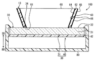
以上の車両用表示装置100の機械的構成を説明する。以下の説明では、図2に示すように、車両用表示装置100の正面が向けられた方向を表示方向SDとし、この表示方向SDとは反対の方向を背面方向BDとする。
The mechanical configuration of the above
車両用表示装置100は、表示器30及びアクリル円筒60等によって構成されている。
The
表示器30は、筐体80に収容されることにより、雰囲気中の塵や埃等から保護されている。表示器30は、液晶パネル31及びバックライト40等を組み合わせることによって構成されている。
The
液晶パネル31は、矩形形状の表示画面32を有している。液晶パネル31は、表示画面32に沿って配列された複数の画素33によって画像を表示する、所謂ドットマトリクス方式の表示器である。各画素33には、赤色(R)、緑色(G)、及び青色(B)の各色のカラーフィルタと組み合わされることにより、各色の光をそれぞれ透過させる三種類のサブ画素が設けられている。各サブ画素の階調値が例えば0〜255の間で制御されることにより、各サブ画素の開口率、ひいては各サブ画素を透過する光の光量が増減する。以上の制御により、各画素の色合いが調整されることで、液晶パネル31は、画像をカラー表示できる。
The
バックライト40は、液晶パネル31の背面方向BDに位置している。バックライト40は、バックライト光源41(図3参照)及び拡散板42を有している。バックライト40は、バックライト光源41から放射された光を拡散板42によって拡散しつつ、拡散した光を表示方向SDに向けて射出する。以上のバックライト40による透過照明により、表示器30は、表示画面32に画像を発光表示することができる。
The
アクリル円筒60は、アクリル樹脂等の透光性の樹脂材料によって円筒状に形成されている。アクリル円筒60は、軸方向を表示方向SDに沿わせた姿勢にて、表示画面32に載置されている。アクリル円筒60は、メイン表示領域10の外縁を囲むように表示画面32の中央に配置されている。アクリル円筒60は、例えば筐体80等によって保持されている。アクリル円筒60は、表示方向SDに向かうに従って、次第に拡径されている。アクリル円筒60は、入射面61、導光部63、及び射出面62を有している。
The
入射面61は、アクリル円筒60の軸方向における両端部のうち、背面方向BDに位置する一方に形成されている。入射面61は、表示画面32に沿った平面状であって、メイン表示領域10を囲む円環状に形成されている。筐体80によるアクリル円筒60の保持により、入射面61は、表示画面32との間に僅かに隙間を開けた状態で、この表示画面32と対向している。入射面61は、複数の画素33の一部(以下、「アンビエント表示画素34」という)と対向している。入射面61は、アンビエント表示画素34を通過し、当該画素34から射出された光をアクリル円筒60の内部に入射させる。尚、入射面61は、表示画面32に接触していてもよい。
The
導光部63は、入射面61から射出面62に向かって延伸している。導光部63は、入射面61から入射した光を射出面62に導光する。導光部63は、アクリル円筒60の軸方向に対して、例えば45°傾斜した姿勢に形成されている。導光部63には、メイン表示領域10側に位置する内周壁面64と、内周壁面64とは反対側の外周側に位置する外周壁面65とが形成されている。径方向における導光部63の厚さが実質的に一定とされることにより、内周壁面64は、外周壁面65に沿った形状とされている。内周壁面64及び外周壁面65は、遮光層66によって覆われている。遮光層66は、遮光性の塗装等によって形成されており、各壁面64,65からの光の漏出及び各壁面64,65への光の入射を抑制する。尚、遮光層66は、アクリル円筒60に組み付けられる遮光性のカバー部材等によって形成されてもよい。
The
射出面62は、アクリル円筒60の軸方向における両端部のうち、表示方向SDに位置する他方に形成されている。射出面62は、表示画面32及び入射面61に沿った平面状であって、メイン表示領域10を囲む円環状に形成されている。射出面62は、外周側に傾斜した導光部63の姿勢により、入射面61よりもメイン表示領域10の外周側に位置している。射出面62は、入射面61からアクリル円筒60に入射した光を表示方向SDに射出することによって発光する。射出面62は、アンビエント発光領域13を形成している。
The
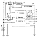
次に、車両用表示装置100の電気的構成を、図3に基づいて、図2を参照しつつ説明する。車両用表示装置100は、上述した液晶パネル31及びバックライト光源41に加えて、メータ制御回路50等によって電気的に構成されている。
Next, the electrical configuration of the
メータ制御回路50は、プログラムに基づいて作動するマイクロコンピュータ等によって構成されている。メータ制御回路50には、車載用のLocal Area Network(車内LAN)91、外部のバッテリ95、及びイグニッション・リレー94等が接続されている。車内LAN91には、電力供給制御装置92等の種々の制御装置が接続されている。電力供給制御装置92は、運転者(視認者)によるイグニッション・スイッチ93の押圧操作を検知して、イグニッション・リレー94に電圧を印加することで、当該リレー94を通電状態にする。
The
メータ制御回路50は、プログラムの実行により、機能ブロックとしての情報取得部53及び液晶制御部51を有する。情報取得部53は、車内LAN91を通じて、車載された種々の制御装置から車両情報を取得する。液晶制御部51は、情報取得部53によって取得された車両情報に基づいて、表示器30を制御する。具体的に液晶制御部51は、各サブ画素の階調値を指示する階調データを生成し、当該階調データに基づいて液晶パネル31の各画素33を駆動させる。また、液晶制御部51は、アンビエント表示画素34から射出される光を制御することにより、取得された車両情報に対応した発光パターンにてアンビエント発光領域13を発光させる。
The
以上の構成では、イグニッション・スイッチ93への入力に基づいて車両のイグニッションがオン状態とされることにより、イグニッション・リレー94が、電圧を印加されて通電状態となる。こうして車両用表示装置100は、図1に示すような、各画像SM,TM等を表示画面32に表示する。
In the above configuration, when the ignition of the vehicle is turned on based on the input to the ignition switch 93, the
次に、アンビエント発光領域13による発光表示の詳細を説明する。アンビエント発光領域13には、図4〜7に示すように、他の発光部分よりも明るく光る高輝度スポット15が複数表示される。高輝度スポット15は、メイン表示領域10の外縁に沿って帯状に延伸する形状である。高輝度スポット15は、情報取得部53(図3参照)によって取得された車両情報に対応する動きにて、アンビエント発光領域13内を移動する。以下、高輝度スポット15を移動させるアンビエント発光領域13の複数の発光パターンを、図4〜7に基づいて順に説明する。
Next, details of light emission display by the ambient
ここで、以下の説明では、アンビエント発光領域13のうちで高輝度スポット15を除く発光区間であって、高輝度スポット15よりも低輝度で発光する他の発光部分を、通常発光部14とする。通常発光部14の面積は、高輝度スポット15の面積よりも広い。また、通常発光部14と高輝度スポット15との間には、輝度及び色差によるコントラスト差が設けられている。尚、図4〜7では、通常発光部14の発光はドットにて模式的に示す。
Here, in the following description, the other light-emitting portion that emits light with lower luminance than the high-
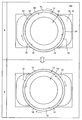
<回転移動パターン>
図4に示す回転移動パターンは、走行用の機関に係る稼動情報等が情報取得部53(図3参照)によって取得された場合に表示される。回転移動パターンによる高輝度スポット15の動きにより、視認者には稼動情報が通知される。この稼動情報は、例えば機関の出力軸の回転速度情報、及び機関による回生ブレーキの作動情報等である。回転移動パターンでは、例えば三つの高輝度スポット15が、アンビエント発光領域13に表示される。これらの高輝度スポット15は、互いに間隔を開けて表示され、メイン表示領域10まわりの周方向に回転移動する。以下、回転移動パターンの具体例を示す。
<Rotation movement pattern>
The rotational movement pattern shown in FIG. 4 is displayed when operation information related to the traveling engine is acquired by the information acquisition unit 53 (see FIG. 3). The movement information of the
機関からの出力により車両が走行している場合、アンビエント発光領域13は、に発光する。また、高輝度スポット15は、時計(右)周りにゆっくりと回転移動する(図4 実線の矢印参照)。そして、取得された回転速度情報の示す回転速度が速くなると、高輝度スポット15の回転速度も次第に速くなり、且つ、アンビエント発光領域13の発光色が橙色に変化する。さらに、機関の回転限界となる回転速度域(レッドゾーン)では、アンビエント発光領域13の発光色は赤色に変化する。以上のアンビエント表示は、発光色の変化だけでなく、高輝度スポット15の移動速度によっても、機関における回転速度の変化を視認者に詳細に示すことができる。尚、高輝度スポット15の移動速度は、機関の回転速度に応じて連続的に変化してもよく、又は段階的に変化してもよい。
When the vehicle is traveling by the output from the engine, the ambient
機関において回生ブレーキが作動している場合、アンビエント発光領域13は、青緑色に発光する。そして、高輝度スポット15は、上述の通常走行時の逆方向となる反時計(左)回りに回転移動する(図4 破線矢印参照)。以上のアンビエント表示は、発光色の変化だけでなく、高輝度スポット15の移動方向の変化によっても、回生ブレーキの作動を視認者に詳細に示すことができる。尚、高輝度スポット15の移動速度は、回生されるエネルギ量に応じて速くされてもよく、又はエネルギの回生量に係らず一定であってもよい。
When the regenerative brake is operating in the engine, the ambient
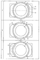
<上下移動パターン>
図5に示す上下移動パターンは、車両の燃費に係る燃費情報、及び自車両の前後方向に位置する他車両の存在を示す前後の警告情報、Adaptive Cruise Control(ACC)の作動情報等が情報取得部53(図3参照)によって取得された場合に表示される。上下移動パターンによる高輝度スポット15の動きにより、視認者には燃費の良否を示す燃費情報、又は前後の車両との車間距離が減少した旨を警告する警告情報等が通知される。上下移動パターンでは、一組の高輝度スポット15が、上下方向に延伸する中心線CL_vを挟んで左右対称に、アンビエント発光領域13に表示される。各高輝度スポット15は、アンビエント発光領域13の上端及び下端の一方から他方へとメイン表示領域10の外縁に沿って移動する。以下、上下移動パターンの具体例を示す。
<Vertical movement pattern>
The up-and-down movement pattern shown in FIG. 5 is obtained from the fuel consumption information related to the vehicle fuel consumption, the warning information before and after the presence of other vehicles located in the front-rear direction of the host vehicle, the operation information of Adaptive Cruise Control (ACC), etc. Displayed when acquired by the unit 53 (see FIG. 3). Due to the movement of the high-
警告情報の示す自車両及び前方車両間の距離が所定の距離未満となった場合、アンビエント発光領域13は、赤色に発光する。そして、高輝度スポット15は、アンビエント発光領域13の上端から下端へと速く移動する(図5 破線矢印参照)。以上のようなアンビエント表示は、車間距離の減少を発光色の変化によって単に警告するだけでなく、上方から下方へと移動する高輝度スポット15によって警告の対象となる事象が車両前方において発生していることを視認者に注意喚起し得る。
When the distance between the host vehicle and the preceding vehicle indicated by the warning information is less than a predetermined distance, the ambient
燃費情報の示す現在の燃費が所定の閾値よりも良好な場合、アンビエント発光領域13は、青緑色に発光する。そして、高輝度スポット15は、アンビエント発光領域13の下端から上端へとゆっくり移動する(図5 実線矢印参照)。一方で、燃費情報の示す現在の燃費が所定の閾値よりも悪化した場合、アンビエント発光領域13は、黄色に発光する。そして、高輝度スポット15は、燃費が良好である場合よりも早い移動速度にてアンビエント発光領域13の下端から上端へと移動する。以上のアンビエント表示は、発光色の変化だけでなく、高輝度スポット15の移動速度によっても、現在の燃費の良否を視認者に詳細に示すことができる。尚、上述した二つの閾値は、同一の値であってもよく、異なる値であってもよい。
When the current fuel consumption indicated by the fuel consumption information is better than a predetermined threshold value, the ambient
ACC装置の作動によって車速が制御されている場合、アンビエント発光領域13は、白緑色に発光する。そして、高輝度スポット15は、アンビエント発光領域13の下端から上端へとゆっくり移動する(図5 実線矢印参照)。以上のアンビエント表示は、発光色の変化だけでは認識し辛いACCの作動を、車両が前進するイメージを惹起させる高輝度スポット15の下方から上方へと移動によって、視認者に分り易く示唆することができる。
When the vehicle speed is controlled by the operation of the ACC device, the ambient
<左右及び斜め移動パターン>
図6に示す左右移動パターン及び図7に示す斜め移動パターンは、自車両の左右方向に位置する他車両等の存在を示す左右の警告情報等が情報取得部53(図3参照)によって取得された場合に表示される。左右移動パターン及び斜め移動パターンによる高輝度スポット15の動きにより、視認者には左右の警告情報が通知される。図6に示す左右移動パターンでは、一組の高輝度スポット15が、左右方向に延伸する中心線CL_hを挟んで上下対称に、アンビエント発光領域13に表示される。各高輝度スポット15は、アンビエント発光領域13の右端及び左端の一方から他方へとメイン表示領域10の外縁に沿って移動する。また、図7に示す斜め移動パターンでは、各高輝度スポット15は、アンビエント発光領域13の右斜上から左斜下に、又は左斜上から右斜下に、メイン表示領域10の外縁に沿って移動する。
<Left / right and diagonal movement patterns>
In the left-right movement pattern shown in FIG. 6 and the diagonal movement pattern shown in FIG. Displayed when The right and left warning information is notified to the viewer by the movement of the high-
例えば図6に示すように、自車両の右側から他車両が接近した場合、アンビエント発光領域13は、黄色から赤色へと発光色を変化させる。そして、高輝度スポット15は、アンビエント発光領域13の右端から左端へと移動する(図6 実線矢印参照)。同様に、自車両の左側から他車両が接近した場合、高輝度スポット15は、アンビエント発光領域13の左端から右端へと移動する(図6 破線矢印参照)。
For example, as shown in FIG. 6, when another vehicle approaches from the right side of the host vehicle, the ambient
また、例えば図7に示すように、右方向に車線変更をする際、自車両と右前方に位置する先行車両との距離が所定の距離未満となった場合、アンビエント発光領域13は、黄色から赤色へと発光色を変化させる。そして、高輝度スポット15は、アンビエント発光領域13の右斜上から左斜下へと移動する(図7 実線矢印参照)。同様に、左方向に車線変更をする際、自車両と左後方に位置する後続車両との距離が所定の距離未満となり、後続車両の進路に支障をきたすような場合、高輝度スポット15は、アンビエント発光領域13の左斜下から右斜上へと移動する(図7 破線矢印参照)。
For example, as shown in FIG. 7, when the lane is changed in the right direction, if the distance between the host vehicle and the preceding vehicle located in the right front is less than a predetermined distance, the ambient
さらに、自車両の右前方に障害物が存在した場合、高輝度スポット15は、アンビエント発光領域13の右斜上から左斜下へと移動する(図7 実線矢印参照)。以上のアンビエント表示は、発光色の変化によって単に他車両等の警告を行うだけでなく、警告の対象となる他車両や障害物の位置を高輝度スポット15の動きによって視認者に通知することができる。
Further, when an obstacle is present on the right front side of the host vehicle, the high-
以上の明るさの異なる高輝度スポット15と通常発光部14とを組み合わせた発光パターンに加えて、車両用表示装置100には、実質的に均一な明るさの発光部17のみでの発光パターンが複数設定されている。発光部17の輝度は、高輝度スポット15相当であってもよく、通常発光部14相当であってもよく、或いはこれらの中間に設定されていてもよい。以下、発光部17による発光パターンを図8,9に基づいて説明する。尚、図8,9において発光部17の発光はドットにて模式的に示す。
In addition to the light emission pattern obtained by combining the high-
<全域消点灯パターン>
図8に示す全域消点灯パターンでは、アンビエント発光領域13の全体が発光部17として、点滅又は点灯する。例えば、上下移動パターンによって警告される車間距離よりも自車両が前方の車両にさらに近接した場合、衝突を警告するために、アンビエント発光領域13は赤色に点滅する。このとき、アンビエント発光領域13は、消灯状態から点灯状態へと、徐々に明るさを変化させる(フェードイン点滅)。
<All area extinction lighting pattern>
In the entire area extinction lighting pattern shown in FIG. 8, the entire ambient
また、何らかの警告すべき事象が発生した場合、アンビエント発光領域13は、赤色での点灯状態を維持する。加えて、メイン表示領域10又は各表示領域11,12に何らかのインジケータが表示された場合、アンビエント発光領域13は、橙色での点灯状態を維持する。
Moreover, when some event that should be warned occurs, the ambient
さらに、シフトアップ及びシフトダウンの操作が入力された場合に、アンビエント発光領域13は、ごく短い時間、発光する。具体的には、シフトアップの操作が入力された場合、アンビエント発光領域13は、青緑色にて瞬灯する。同様に、シフトダウンの操作が入力された場合、アンビエント発光領域13は、黄色にて瞬灯する。
Further, when a shift up and shift down operation is input, the ambient
<部分消点灯パターン>
図9に示す部分消点灯パターンでは、アンビエント発光領域13の一部が発光部17として、点滅する。例えば、右方向の方向指示器が作動している場合、アンビエント発光領域13の右半分の範囲が緑色に点滅する。同様に、左方向の方向指示器が作動している場合、アンビエント発光領域13の左半分の範囲が緑色に点滅する。尚、図9において、消灯状態にある左半分の範囲は、発光部17よりも高密度のドットにて模式的に示す。
<Partial extinction lighting pattern>
In the partial light-off pattern shown in FIG. 9, a part of the ambient
また、駐車時にソナーによって車両周囲の障害物が検知された場合、アンビエント発光領域13の一部が点滅する。具体的には、車両の後方に障害物が検知された場合、アンビエント発光領域13の下半分の範囲が黄色に点滅する。同様に、車両の前方に障害物が検知された場合、アンビエント発光領域13の上半分の範囲が黄色に点滅する。
Further, when an obstacle around the vehicle is detected by the sonar during parking, a part of the ambient
尚、アンビエント発光領域13のうちで消点灯する部分は、円環状の半分でなくてもよく、例えば4分の1の範囲や3分の1の範囲であってもよい。
In addition, the part turned off in the ambient
以上のような種々の発光パターンでアンビエント発光領域13を発光させる表示制御処理を、図10に基づいて以下説明する。表示制御処理は、例えば車両のイグニッションがオン状態とされることにより、メータ制御回路50によって開始される。この表示制御処理は、車両のイグニッションがオフ状態とされるまで、メータ制御回路50によって継続される。
A display control process for causing the ambient
S101では、車内LAN91に出力された車両情報を情報取得部53(図3参照)によって取得し、S102に進む。S102では、S101にて取得した車両情報に基づいて、アンビエント発光領域13に表示する発光パターンを決定し、S103に進む。S103では、S102にて決定した発光パターンをアンビエント発光領域13に表示させるために、アンビエント表示画素34(図2参照)の制御を開始する。具体的に、S103では、液晶制御部51によってアンビエント表示画素34の階調データを生成し、当該階調データに基づいてアンビエント表示画素34を駆動する。そして、再びS101に戻り、上述の処理を繰り返す。
In S101, the vehicle information output to the in-
ここまで説明した第一実施形態では、アンビエント表示画素34からアクリル円筒60に入射する光により、アンビエント発光領域13が発光する。こうした構成であれば、アンビエント発光領域13は、通常発光部14との間にコントラスト差を有する高輝度スポット15を表示し、且つ、所定の動きにて高輝度スポット15を移動させることができる。故に視認者は、アンビエント発光領域13の単なる発光によって何らかの状況変化を知覚したうえで、高輝度スポット15の移動によって何が起きたのかを、さらに具体的に知覚することができるようになる。
In the first embodiment described so far, the ambient
加えて、メイン表示領域10を囲むように形成されたアンビエント発光領域13の形態により、高輝度スポット15は、上下方向及び左右方向に移動することができる。故に、周辺視野にてアンビエント発光領域13を視認した場合でも、高輝度スポット15の動きは、視認者に知覚され易くなる。以上によれば、車両用表示装置100は、アンビエント表示によって詳細な情報を視認者に伝えることが可能となる。
In addition, the high-
さらに第一実施形態では、高輝度スポット15を通常発光部14よりも明るく表示させることにより、これらの間のコントラスト差が確保されている。故に視認者は、周辺視野による視認であっても、高輝度スポット15の動きを知覚し易くなる。その結果、アンビエント表示による詳細な情報の伝達は、高い確実性をもって実現可能となる。
Furthermore, in the first embodiment, the high-
また第一実施形態では、表示画面32、入射面61、及び射出面62の向きが互いに揃えられている。故に、アンビエント表示画素34から射出された光が入射面61及び射出面62を通過する際の屈折は、抑制される。そのため、アンビエント表示画素34に発光表示された画像は、滲むことなく射出面62に投影され得る。以上により、アンビエント発光領域13には、移動する高輝度スポット15が鮮明に表示される。
In the first embodiment, the orientations of the
加えて第一実施形態では、導光部63の内周壁面64と外周壁面65の向きが互いに揃えられることにより、アンビエント表示画素34に表示された画像の光が導光部63を進むうちに歪む事態は、回避され得る。故に、アンビエント表示画素34に発光表示された画像は、滲むことなく射出面62に投影され得る。その結果、アンビエント発光領域13に表示される高輝度スポット15の移動は、いっそう鮮明となる。
In addition, in the first embodiment, the directions of the inner
さらに第一実施形態では、射出面62が入射面61よりもメイン表示領域10の外周側に位置しているため、射出面62によって形成されるアンビエント発光領域13は、表示画面32においてアンビエント表示画素34の配置される領域よりも、大きくなる。こうしてアンビエント発光領域13が表示上での存在感を獲得することにより、当該領域13内を移動する高輝度スポットは、視認者にさらに知覚され易くなる。したがって、視認者に詳細な情報がいっそう伝わり易くなる。
Furthermore, in the first embodiment, since the
また加えて第一実施形態では、複数の高輝度スポット15が連動してアンビエント発光領域13内を移動する。こうした表示であれば、視認者の周辺視野による知覚は、さらに容易となる。故に、アンビエント表示による詳細な情報伝達の確実性が、いっそう向上可能となる。
In addition, in the first embodiment, the plurality of high-
さらに加えて、回転移動パターンによる高輝度スポット15の回転移動は、内燃機関やモータの出力軸のイメージを視認者に惹起させ得る。故に、走行用の機関の稼動情報を高輝度スポット15の回転移動によって表示することで、アンビエント発光領域13は、詳細な情報を視認者に分り易く通知することができる。
In addition, the rotational movement of the high-
また、上下移動パターンによる高輝度スポット15の移動は、車両の前後方向への動きを視認者に惹起させ得る。故に、燃費情報や前後の警告情報、ACCの作動情報等を高輝度スポット15の上下移動によって表示することで、アンビエント発光領域13は、詳細な情報を視認者に分り易く通知することができる。
In addition, the movement of the high-
同様に、左右及び斜め移動パターンによる高輝度スポット15の移動は、車両の周囲に運転者の注意を誘導し得る。故に、警告の対象となる他車両等の方向と対応するように高輝度スポット15の移動開始位置を設定することにより、アンビエント発光領域13は、視認者にとって分かり易い警告を、周辺視野を通じて実施することができる。
Similarly, the movement of the high-
尚、第一実施形態において、メイン表示領域10が特許請求の範囲に記載の「表示領域」に相当し、アンビエント発光領域13が特許請求の範囲に記載の「発光領域」に相当し、通常発光部14が特許請求の範囲に記載の「他の部分」に相当する。また、表示器30が特許請求の範囲に記載の「表示手段」に相当し、アンビエント表示画素34が特許請求の範囲に記載の「対向画素」に相当し、液晶制御部51が特許請求の範囲に記載の「制御手段」に相当する。そして、情報取得部53が特許請求の範囲に記載の「情報取得手段」に相当し、アクリル円筒60が特許請求の範囲に記載の「透光部材」に相当し、高輝度スポット15が特許請求の範囲に記載の「特定発光スポット」に相当する。
In the first embodiment, the
(第二実施形態)
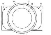
図11に示す本発明の第二実施形態は、第一実施形態の変形例である。第二実施形態におけるアンビエント発光領域213は、メイン表示領域210を囲むU字状に形成されている。こうしたアンビエント発光領域213を形成するため、第二実施形態の車両用表示装置200は、第一実施形態のアクリル円筒60(図1参照)に相当する透光部材260を備えている。
(Second embodiment)
The second embodiment of the present invention shown in FIG. 11 is a modification of the first embodiment. The ambient
透光部材260は、U字状に湾曲させたアクリルの板材によって形成されている。透光部材260は、アクリル円筒60(図1参照)と同様に、入射面261、導光部263、及び射出面262を有している。入射面261は、メイン表示領域210の外縁に沿ってU字状に延伸している。導光部263は、表示画面32に対して実質的に垂直に立設されている。こうした導光部263の形状により、射出面262は、入射面261と実質同一の形状となり、且つ、表示方向SD(図2参照)において入射面261と重なって位置している。以上の射出面262によって、メイン表示領域210をU字状に囲むアンビエント発光領域213が形成されている。
The
ここまで説明した第二実施形態のように、アンビエント発光領域213が連続した円環状でなくても、発光するアンビエント発光領域213中に高輝度スポット15を表示させ、且つ、この高輝度スポット15を移動させる表示は、可能である。故に、車両用表示装置200は、第一実施形態と同様の効果を奏し、アンビエント表示によって視認者に詳細な情報を伝えることができる。
As in the second embodiment described so far, even if the ambient
加えて第二実施形態では、表示画面32に対し垂直な導光部263の形状により、入射面261に入射した光は、滲むことなく表示方向SD(図2参照)に進み、射出面262に投影され得る。そのため、アンビエント発光領域213に表示される高輝度スポット15の移動は、いっそう鮮明となる。
In addition, in the second embodiment, due to the shape of the
尚、第二実施形態において、メイン表示領域210が特許請求の範囲に記載の「表示領域」に相当し、アンビエント発光領域213が特許請求の範囲に記載の「発光領域」に相当する。
In the second embodiment, the
(第三実施形態)
図12に示す本発明の第三実施形態は、第一実施形態の別の変形例である。第三実施形態におけるアンビエント発光領域313は、メイン表示領域10を円環状に囲みつつ、部分的に途切れた形状とされている。こうしたアンビエント発光領域313を形成するため、車両用表示装置300は、第一実施形態のアクリル円筒60(図1参照)に相当する透光部材360を備えている。
(Third embodiment)
The third embodiment of the present invention shown in FIG. 12 is another modification of the first embodiment. The ambient
透光部材360は、円弧状に湾曲させたアクリルの板材を複数(四つ)組み合わせることによって形成されている。透光部材360は、アクリル円筒60(図1参照)と同様に、入射面361、導光部363、及び射出面362を有している。入射面361は、メイン表示領域10の外縁に沿って延伸する円弧状に形成されている。導光部363は、表示画面32に対して実質的に垂直に立設されている。こうした導光部363の形状により、射出面362は、入射面361と実質同一の形状となり、且つ、表示方向SD(図2参照)において入射面361と重なって位置している。以上の射出面362によって、部分的に途切れつつメイン表示領域10を円環状に囲むアンビエント発光領域313が形成されている。
The
ここまで説明した第三実施形態のように、アンビエント発光領域313が部分的に途切れていても、発光するアンビエント発光領域313中に高輝度スポット15を表示させ、且つ、この高輝度スポット15を移動させる表示は、可能である。故に、車両用表示装置300は、第一実施形態と同様の効果を奏し、アンビエント表示によって視認者に詳細な情報を伝えることができる。
As in the third embodiment described so far, even if the ambient
尚、第三実施形態において、アンビエント発光領域313が特許請求の範囲に記載の「発光領域」に相当する。
In the third embodiment, the ambient
(第四実施形態)
図13に示す本発明の第四実施形態は、第一実施形態のさらに別の変形例である。第四実施形態による車両用表示装置400には、第一実施形態と実質同一のアンビエント発光領域413がアクリル円筒60によって形成されている。アンビエント発光領域413には、通常発光部414及び低輝度スポット415がそれぞれ複数表示される。尚、図13では、低輝度スポット415の発光を、ドットにて模式的に示す。
(Fourth embodiment)
The fourth embodiment of the present invention shown in FIG. 13 is yet another modification of the first embodiment. In the
低輝度スポット415は、第一実施形態の高輝度スポット15(図4等参照)と同様に、メイン表示領域10の外縁に沿って帯状に延伸する形状に表示される。低輝度スポット415は、例えば暗い赤色に発光する。一方、通常発光部414は、例えば明るい赤色に発光する。低輝度スポット415は、通常発光部414よりも暗く光ることにより、この通常発光部414との間にコントラスト差を有する。低輝度スポット415の面積は、通常発光部414の面積よりも狭い。低輝度スポット415は、車両情報に対応する動きにてアンビエント発光領域413内を移動する。第四実施形態における低輝度スポット415は、回転移動に加えて、上下方向、左右方向、及び斜め方向等への移動も可能である。
The low-
ここまで説明した第四実施形態のように、通常発光部414よりも低輝度の低輝度スポット415を移動させる表示であっても、視認者は、こうした低輝度スポット415の動きを周辺視野にて知覚することができる。故に、車両用表示装置400は、第一実施形態と同様の効果を奏し、アンビエント表示における低輝度スポット415の移動により、具体的に何が起きたのかを視認者に通知可能となる。
Even in the display in which the
尚、第四実施形態において、低輝度スポット415が特許請求の範囲に記載の「特定発光スポット」に相当する。
In the fourth embodiment, the
(他の実施形態)
以上、本発明による複数の実施形態について説明したが、本発明は、上記実施形態に限定して解釈されるものではなく、本発明の要旨を逸脱しない範囲内において種々の実施形態及び組み合わせに適用することができる。
(Other embodiments)
Although a plurality of embodiments according to the present invention have been described above, the present invention is not construed as being limited to the above embodiments, and can be applied to various embodiments and combinations without departing from the gist of the present invention. can do.
上記第一実施形態では、輝度差及び色差によって、高輝度スポットと通常発光部とのコントラスト差が確保されていた。また、第四実施形態では、低輝度スポットと通常発光部とのコントラスト差は、これらの間の輝度差によって確保されていた。以上のように、視認者によって識別可能なコントラスト差が確保されるのであれば、特定発光スポット及び通常発光部の各発光色は、適宜変更可能である。 In the first embodiment, the contrast difference between the high-intensity spot and the normal light emitting unit is ensured by the brightness difference and the color difference. In the fourth embodiment, the contrast difference between the low brightness spot and the normal light emitting portion is ensured by the brightness difference between them. As described above, the light emission colors of the specific light emission spot and the normal light emission part can be appropriately changed as long as a contrast difference that can be identified by a viewer is secured.
以上のコントラスト差について、図14を用いてさらに詳しく説明する。特定発光スポットの発光色と通常発光部の発光色との間にコントラスト差がある場合、国際照明委員会(CIE)の規定するL*a*b*表色系の色空間において、各発光色は、互いに異なる座標にプロットされる。具体的に、二つの発光色の間に色差がある場合、各発光色の座標は、a*の値及びb*の値のうち少なくとも一方が異なる。加えて、二つの発光色の間に輝度差がある場合、各発光色の座標は、L*の値が異なる。二つの発光色の座標位置が色空間において互いに離れるほど、コントラスト差は大きくなる。 The above contrast difference will be described in more detail with reference to FIG. When there is a contrast difference between the emission color of the specific emission spot and the emission color of the normal emission part, each emission color in the color space of the L * a * b * color system defined by the International Commission on Illumination (CIE) Are plotted at different coordinates. Specifically, when there is a color difference between two luminescent colors, the coordinates of each luminescent color are different in at least one of a * and b * values. In addition, when there is a luminance difference between the two emission colors, the coordinates of each emission color have different L * values. As the coordinate positions of the two luminescent colors are separated from each other in the color space, the contrast difference increases.
例えば、二つの発光色は、L*の座標軸上に位置していてもよい。この場合、各発光色は、共に無彩色となる。又は、一方の発光色がL*の座標軸上に位置し、他方の発光色がL*の座標軸から外れて位置していてもよい。この場合、一方の発光色が無彩色となり、他方の発光色が有彩色となる。以上のように、発光色の少なくとも一方が無彩色であっても、コントラスト差は確保可能である。さらに、第四実施形態のような低輝度スポットを表示する形態において、低輝度スポットと通常発光部との間に色差が設けられていてもよい。 For example, the two emission colors may be located on the coordinate axis of L *. In this case, each emission color is an achromatic color. Alternatively, one emission color may be positioned on the L * coordinate axis, and the other emission color may be positioned off the L * coordinate axis. In this case, one emission color is an achromatic color and the other emission color is a chromatic color. As described above, a contrast difference can be ensured even if at least one of the emission colors is an achromatic color. Furthermore, in the form of displaying the low brightness spot as in the fourth embodiment, a color difference may be provided between the low brightness spot and the normal light emitting unit.
また、二つの発光色のコントラスト差は、色彩輝度計等の計器により、特定発光スポット及び通常発光部の各輝度(L*の値)及び各色度(a*及びb*の各値)を計測することで評価可能である。二つの発光色の座標位置は、所定の距離以上、離れていることが望ましい。この所定距離は、視認者による色差の識別限界を表すMacAdamの楕円に基づいて、規定可能である。 Also, the contrast difference between the two luminescent colors is measured by measuring the brightness (L * value) and chromaticity (values of a * and b *) of the specific luminescent spot and the normal light emitting part with an instrument such as a color luminance meter. Can be evaluated. It is desirable that the coordinate positions of the two emission colors be separated by a predetermined distance or more. This predetermined distance can be defined based on a MacAdam ellipse that represents a color difference identification limit by the viewer.
上記実施形態において、入射面61及び射出面62は、表示画面32に沿った平面状に形成されていた。しかし、アンビエント発光領域に表示される表示像の歪みが許容される範囲内であれば、入射面及び射出面の形状は、表示画面に対して傾斜していてもよく、又は平面状でなくてもよい。また、表示像の歪みが許容される範囲内であれば、導光部の板厚は、一定でなくてもよい。加えて、表示方向SDに沿った軸線に対する導光部の傾斜は、第一実施形態のように45°に限定されず、適宜変更されてよい。さらに、導光部は、省略されていてもよい。
In the above embodiment, the
上記実施形態において、円環状又はU字状とされていたアンビエント発光領域の形状は、メイン表示領域を囲む形状であれば適宜変更されてよい。例えば、楕円状、三角形状、又は矩形状のアンビエント発光領域が形成されていてもよい。また、アンビエント発光領域の位置は、車両用表示装置の中央でなくてもよい。さらに、複数のアンビエント発光領域が車両用表示装置に設けられていてもよい。 In the above-described embodiment, the shape of the ambient light emitting region that has been formed into an annular shape or a U shape may be changed as long as the shape surrounds the main display region. For example, an ambient light emitting region having an elliptical shape, a triangular shape, or a rectangular shape may be formed. In addition, the position of the ambient light emission region may not be the center of the vehicle display device. Furthermore, a plurality of ambient light emitting areas may be provided in the vehicle display device.
上記実施形態において、アクリル樹脂であった「透光部材」の材料は、適宜変更されてよい。例えば、ポリカーボネート樹脂やガラス等が「透光部材」の材料として採用されていてもよい。さらに、「透光部材」は、無色透明でなくてもよく、特定の色に着色されていてもよい。 In the said embodiment, the material of the "translucent member" which was an acrylic resin may be changed suitably. For example, polycarbonate resin, glass, or the like may be employed as the material of the “translucent member”. Further, the “translucent member” may not be colorless and transparent, and may be colored in a specific color.
上記実施形態では、複数の高輝度スポット15は、互いの間隔を維持しながら、連動して移動していた。しかし、複数の高輝度スポットは、互いに異なる動きをしてもよい。例えば、複数の高輝度スポットが、互いに異なる回転方向に形状及び発光色を変えながら移動してもよい。さらに、同時にアンビエント発光領域に表示される高輝度スポットの数も、適宜変更可能である。また、通常発光部中にて高輝度スポットを移動させる発光パターンは、上述したものに限定されない。
In the above-described embodiment, the plurality of high-
上記実施形態において、アクリル円筒60の板厚が10ミリメートル程度であれば、アクリル円筒60の板厚方向に並ぶアンビエント表示画素34の数は、例えば10〜30程度となる。このような入射面と対向する「対向画素」の数は、適宜調整されてよい。しかしながら、「対向画素」の密度が高くなるほど、緻密な表示像をアンビエント発光領域に投影することが可能となる。
In the above embodiment, if the thickness of the
上記実施形態において、液晶パネル31及びバックライト40が組み合わされていた「表示手段」の構成は、適宜変更されてよい。例えば、液晶パネルは、単色の発光表示のみが可能な構成であってもよい。さらに、Organic light-emitting diode(OLED)のような自発光素子によって画像を発光表示するディスプレイパネルが「表示手段」として用いられていてもよい。OLEDは、液晶パネルと同様に、「制御手段」から取得する階調データに基づいて、各サブ画素の階調値を制御することにより、種々の画像をフルカラーで表示できる。
In the above embodiment, the configuration of the “display unit” in which the
上記実施形態において、液晶制御部51及び情報取得部53を機能ブロックとして有していたメータ制御回路50は、上述のものとは異なるハードウェア及びソフトウェア、或いはこれらの組み合わせによって提供されてよい。例えば、プログラムによらないで所定の機能を果たすアナログ回路によって、上述のメータ制御回路が構成されていてもよい。
In the above embodiment, the
10,210 メイン表示領域(表示領域)、13,213,313,413 アンビエント発光領域(発光領域)、14,414 通常発光部(他の発光部分)、15 高輝度スポット(特定発光スポット)、415 低輝度スポット(特定発光スポット)、30 表示器(表示手段)、33 画素、34 アンビエント表示画素(対向画素)、51 液晶制御部(制御手段)、53 情報取得部(情報取得手段)、60 アクリル円筒(透光部材)、260,360 透光部材、61,261,361 入射面、62,262,362 射出面、63,263,363 導光部、64 内周壁面、65 外周壁面、100,200,300,400 車両用表示装置 10, 210 Main display area (display area), 13, 213, 313, 413 Ambient light emitting area (light emitting area), 14,414 Normal light emitting part (other light emitting parts), 15 High brightness spot (specific light emitting spot), 415 Low luminance spot (specific light emission spot), 30 display (display means), 33 pixels, 34 ambient display pixels (opposing pixels), 51 liquid crystal control section (control means), 53 information acquisition section (information acquisition means), 60 acrylic Cylindrical (translucent member), 260, 360 Translucent member, 61, 261, 361 Incident surface, 62, 262, 362 Ejection surface, 63, 263, 363 Light guide unit, 64 Inner peripheral wall surface, 65 Outer peripheral wall surface, 100, 200, 300, 400 Display device for vehicle
Claims (11)
表示画面(32)を有し、画像を発光表示する複数の画素(33)が前記表示画面に沿って配列される表示手段(30)と、
前記複数の画素の一部と対向する入射面(61,261,361)、前記入射面から入射した光を射出することで前記発光領域を形成する射出面(62,262,362)、及び前記入射面から前記射出面に向かって延伸する導光部(63,263,363)を有し、前記射出面を前記入射面よりも前記表示領域の外周側に位置させており、且つ、外周側に傾斜する前記導光部において前記表示領域側に位置する内周壁面(64)が遮光性の遮光層(66)によって覆われている透光部材(60,260,360)と、
前記車両情報を取得する情報取得手段(53)と、
前記情報取得手段によって取得された前記車両情報に基づいて、前記入射面と対向する対向画素(34)から射出される光を制御することにより、当該車両情報に対応した発光パターンにて前記発光領域を発光させる制御手段(51)と、を備え、
前記制御手段は、前記対向画素を制御することにより、他の発光部分(14,414)との間にコントラスト差を設けた特定発光スポット(15,415)を、発光する前記発光領域中に表示させ、且つ、取得された前記車両情報に対応する動きにて前記特定発光スポットを移動させることを特徴とする車両用表示装置。 A vehicle mounted on a vehicle and formed so that a light emitting region (13, 213, 313, 413) that emits light when it emits light surrounds a display region (10, 210) that displays vehicle information related to the vehicle. Display device,
A display means (30) having a display screen (32) and having a plurality of pixels (33) for emitting and displaying an image arranged along the display screen;
Incident surface facing the portion of the plurality of pixels (61,261,361), an exit surface forming the luminous area by emitting light incident from the entering morphism surface (62,262,362), and the light guide portion that extends toward the exit surface from the entrance surface has a (63,263,363), and the pre-Symbol exit surface than the incident surface is located at the outer periphery of the display area, and, wherein an inner circumferential wall surface (64) of the translucent member that is covered by the light-shielding of the light shielding layer (66) located on the display region side (60,260,360) in the light guide portion inclined to the outer peripheral side,
Information acquisition means (53) for acquiring the vehicle information;
Based on the vehicle information acquired by the information acquisition means, by controlling the light emitted from the opposing pixel (34) facing the incident surface, the light emitting area in a light emission pattern corresponding to the vehicle information Control means (51) for emitting light,
The control means displays the specific light-emitting spot (15, 415) having a contrast difference with the other light-emitting portions (14, 414) in the light-emitting region that emits light by controlling the counter pixel. And the specific light emission spot is moved by a movement corresponding to the acquired vehicle information.
前記射出面は、前記入射面に沿った平面状に形成されることを特徴とする請求項1に記載の車両用表示装置。 The incident surface is formed in a planar shape along the display screen,
The vehicle display device according to claim 1, wherein the emission surface is formed in a planar shape along the incident surface.
複数の前記特定発光スポットは、取得された前記車両情報に対応した動きにて前記発光領域中を移動することを特徴とする請求項1〜6のいずれか一項に記載の車両用表示装置。 In the light emitting area, a plurality of the specific light emitting spots are displayed,
The vehicular display device according to any one of claims 1 to 6, wherein the plurality of specific light emission spots move in the light emission region by movement corresponding to the acquired vehicle information.
前記制御手段は、前記情報取得手段によって前記稼動情報が取得された場合に、前記表示領域まわりの周方向に前記特定発光スポットが回転移動するよう、前記対向画素を制御することを特徴とする請求項1〜7のいずれか一項に記載の車両用表示装置。 The information acquisition means acquires operation information relating to a traveling engine mounted on the vehicle as the vehicle information,
The said control means controls the said opposing pixel so that the said specific light emission spot may rotate in the circumferential direction around the said display area, when the said operation information is acquired by the said information acquisition means. Item 8. The vehicle display device according to any one of Items 1 to 7.
前記制御手段は、
前記情報取得手段の取得した前記車両情報に基づいて、複数設定された前記発光パターンから一つの前記発光パターンを決定し、
前記情報取得手段によって前記燃費情報が取得された場合には、前記表示領域の上下方向に前記特定発光スポットが移動するよう、前記対向画素を制御することを特徴とする請求項1〜8のいずれか一項に記載の車両用表示装置。 The information acquisition means acquires fuel consumption information related to fuel consumption of the vehicle as the vehicle information,
Wherein,
Based on the vehicle information acquired by the information acquisition means, determine one light emission pattern from a plurality of light emission patterns set,
When the fuel consumption information is acquired by the information acquisition means, so that the specific luminous spot in the vertical direction of the display area is moved, any of claims 1 to 8, wherein the controller controls the counter pixel The vehicle display device according to claim 1.
前記制御手段は、
前記情報取得手段の取得した前記車両情報に基づいて、複数設定された前記発光パターンから一つの前記発光パターンを決定し、
前記情報取得手段によって前記前後の警告情報が取得された場合には、前記表示領域の上下方向に前記特定発光スポットが移動するよう、前記対向画素を制御することを特徴とする請求項1〜9のいずれか一項に記載の車両用表示装置。 The information acquisition means acquires warning information before and after indicating the presence of another vehicle positioned in the front-rear direction of the vehicle as the vehicle information,
Wherein,
Based on the vehicle information acquired by the information acquisition means, determine one light emission pattern from a plurality of light emission patterns set,
When the front and rear warning information is acquired by the information acquisition means, so that the specific luminous spot in the vertical direction of the display area is moved, claim 1 to 9, wherein the controller controls the counter pixel The vehicle display device according to any one of the above.
前記制御手段は、
前記情報取得手段の取得した前記車両情報に基づいて、複数設定された前記発光パターンから一つの前記発光パターンを決定し、
前記情報取得手段によって前記左右の警告情報が取得された場合には、前記表示領域の左右方向又は斜め方向に前記特定発光スポットが移動するよう、前記対向画素を制御することを特徴とする請求項1〜10のいずれか一項に記載の車両用表示装置。 The information acquisition means acquires left and right warning information indicating the presence of another vehicle located in the left-right direction of the vehicle as the vehicle information,
Wherein,
Based on the vehicle information acquired by the information acquisition means, determine one light emission pattern from a plurality of light emission patterns set,
Claim when warning information of the left and right is acquired by the information acquisition means, the specific luminous spots in the left-right direction or an oblique direction of the display area to move, characterized by controlling the counter pixel The vehicle display device according to any one of 1 to 10.
Priority Applications (2)
| Application Number | Priority Date | Filing Date | Title |
|---|---|---|---|
| JP2014085862A JP6011575B2 (en) | 2013-07-01 | 2014-04-17 | Vehicle display device |
| PCT/JP2014/003378 WO2015001765A1 (en) | 2013-07-01 | 2014-06-24 | Vehicle display device |
Applications Claiming Priority (3)
| Application Number | Priority Date | Filing Date | Title |
|---|---|---|---|
| JP2013138097 | 2013-07-01 | ||
| JP2013138097 | 2013-07-01 | ||
| JP2014085862A JP6011575B2 (en) | 2013-07-01 | 2014-04-17 | Vehicle display device |
Publications (3)
| Publication Number | Publication Date |
|---|---|
| JP2015027868A JP2015027868A (en) | 2015-02-12 |
| JP2015027868A5 JP2015027868A5 (en) | 2015-07-23 |
| JP6011575B2 true JP6011575B2 (en) | 2016-10-19 |
Family
ID=52143368
Family Applications (1)
| Application Number | Title | Priority Date | Filing Date |
|---|---|---|---|
| JP2014085862A Expired - Fee Related JP6011575B2 (en) | 2013-07-01 | 2014-04-17 | Vehicle display device |
Country Status (2)
| Country | Link |
|---|---|
| JP (1) | JP6011575B2 (en) |
| WO (1) | WO2015001765A1 (en) |
Families Citing this family (3)
| Publication number | Priority date | Publication date | Assignee | Title |
|---|---|---|---|---|
| JP6256424B2 (en) | 2015-07-09 | 2018-01-10 | 株式会社デンソー | Vehicle display device |
| JP6531561B2 (en) * | 2015-08-24 | 2019-06-19 | 日本精機株式会社 | Display device |
| CN109677266B (en) * | 2019-01-31 | 2022-03-29 | 大陆汽车车身电子系统(芜湖)有限公司 | Wading state display method for vehicle |
Family Cites Families (7)
| Publication number | Priority date | Publication date | Assignee | Title |
|---|---|---|---|---|
| JP3522400B2 (en) * | 1995-08-11 | 2004-04-26 | リーダー電子株式会社 | Flow display type pointing method and device |
| JP2991203B1 (en) * | 1998-12-18 | 1999-12-20 | 日本精機株式会社 | Display device for vehicles |
| JP3880772B2 (en) * | 2000-04-19 | 2007-02-14 | カルソニックカンセイ株式会社 | Dial of vehicle instrument |
| JP4930315B2 (en) * | 2007-01-19 | 2012-05-16 | 株式会社デンソー | In-vehicle information display device and light irradiation device used therefor |
| JP2009042120A (en) * | 2007-08-09 | 2009-02-26 | Denso Corp | Composite measuring meter |
| JP5321226B2 (en) * | 2009-04-27 | 2013-10-23 | 日本精機株式会社 | Vehicle display device |
| JP2012192799A (en) * | 2011-03-15 | 2012-10-11 | Yupiteru Corp | Vehicle information display system and program |
-
2014
- 2014-04-17 JP JP2014085862A patent/JP6011575B2/en not_active Expired - Fee Related
- 2014-06-24 WO PCT/JP2014/003378 patent/WO2015001765A1/en active Application Filing
Also Published As
| Publication number | Publication date |
|---|---|
| JP2015027868A (en) | 2015-02-12 |
| WO2015001765A1 (en) | 2015-01-08 |
Similar Documents
| Publication | Publication Date | Title |
|---|---|---|
| CN109964101B (en) | Display device for vehicle | |
| WO2016021102A1 (en) | Vehicle display device | |
| US10513220B2 (en) | Display device with backlight | |
| WO2015040851A1 (en) | Vehicular display device | |
| WO2014199629A1 (en) | Display device for vehicle | |
| JP2007071540A (en) | Display device for vehicle | |
| JP6510229B2 (en) | Display device | |
| JP6015722B2 (en) | Display device | |
| JP6011575B2 (en) | Vehicle display device | |
| JP5979198B2 (en) | Display device | |
| KR100660673B1 (en) | Combination meter for cars | |
| JP4984847B2 (en) | Display device | |
| US9862274B2 (en) | Display device for vehicle | |
| JP6500621B2 (en) | Display device | |
| JP4952458B2 (en) | Display device | |
| JP6256248B2 (en) | Vehicle display device | |
| JP5962595B2 (en) | Vehicle display device | |
| JP5910848B2 (en) | Vehicle display device | |
| JP2011075375A (en) | Display apparatus | |
| JP2009186400A (en) | Lighting structure of instrument for vehicle | |
| JP2004233701A (en) | Display device | |
| US20240001843A1 (en) | Display device | |
| JP2008170220A (en) | Display apparatus for vehicle | |
| JP5228687B2 (en) | Vehicle display device | |
| JP6406808B2 (en) | Vehicle instrumentation |
Legal Events
| Date | Code | Title | Description |
|---|---|---|---|
| A521 | Request for written amendment filed |
Free format text: JAPANESE INTERMEDIATE CODE: A523 Effective date: 20150608 |
|
| A621 | Written request for application examination |
Free format text: JAPANESE INTERMEDIATE CODE: A621 Effective date: 20150610 |
|
| A621 | Written request for application examination |
Free format text: JAPANESE INTERMEDIATE CODE: A621 Effective date: 20150610 |
|
| A131 | Notification of reasons for refusal |
Free format text: JAPANESE INTERMEDIATE CODE: A131 Effective date: 20160517 |
|
| A521 | Request for written amendment filed |
Free format text: JAPANESE INTERMEDIATE CODE: A523 Effective date: 20160714 |
|
| TRDD | Decision of grant or rejection written | ||
| A01 | Written decision to grant a patent or to grant a registration (utility model) |
Free format text: JAPANESE INTERMEDIATE CODE: A01 Effective date: 20160823 |
|
| A61 | First payment of annual fees (during grant procedure) |
Free format text: JAPANESE INTERMEDIATE CODE: A61 Effective date: 20160905 |
|
| R151 | Written notification of patent or utility model registration |
Ref document number: 6011575 Country of ref document: JP Free format text: JAPANESE INTERMEDIATE CODE: R151 |
|
| R250 | Receipt of annual fees |
Free format text: JAPANESE INTERMEDIATE CODE: R250 |
|
| R250 | Receipt of annual fees |
Free format text: JAPANESE INTERMEDIATE CODE: R250 |
|
| R250 | Receipt of annual fees |
Free format text: JAPANESE INTERMEDIATE CODE: R250 |
|
| LAPS | Cancellation because of no payment of annual fees |