JP6010930B2 - Electronic clock - Google Patents
Electronic clock Download PDFInfo
- Publication number
- JP6010930B2 JP6010930B2 JP2012047251A JP2012047251A JP6010930B2 JP 6010930 B2 JP6010930 B2 JP 6010930B2 JP 2012047251 A JP2012047251 A JP 2012047251A JP 2012047251 A JP2012047251 A JP 2012047251A JP 6010930 B2 JP6010930 B2 JP 6010930B2
- Authority
- JP
- Japan
- Prior art keywords
- battery
- voltage
- hand
- electronic timepiece
- secondary battery
- Prior art date
- Legal status (The legal status is an assumption and is not a legal conclusion. Google has not performed a legal analysis and makes no representation as to the accuracy of the status listed.)
- Active
Links
Images


Description
本発明は、電子時計にかかり、特に電力消費が大きな負荷を有する電子時計に関する。 The present invention relates to an electronic timepiece, and more particularly to an electronic timepiece having a load that consumes a large amount of power.
従来、腕時計等の携帯型の時計は、一次電池や二次電池の電力で駆動される。このため、電池電圧が低下すると、水晶振動子やIC等で構成される計時回路が停止して、計時機能を維持できなくなり、時計として機能しなくなる。
従って、電池電圧がICなどを駆動できない電圧(停止電圧)に低下する前に、BLD運針を行うことで、利用者に電池電圧が低下していることを知らせるものがある(例えば特許文献1参照)。
なお、BLD運針とは、電池電圧低下表示(Battery Low Display)や、電池寿命切れ予告表示(battery life indicator)などと呼ばれる運針であり、特許文献1では、秒針を2秒ごとに2秒分運針させて、通常の運針と異なる動作をさせている。
Conventionally, a portable timepiece such as a wristwatch is driven by the power of a primary battery or a secondary battery. For this reason, when the battery voltage decreases, the time measuring circuit composed of a crystal resonator, an IC, or the like stops, so that the time measuring function cannot be maintained and the timepiece does not function.
Therefore, there is one that informs the user that the battery voltage is reduced by performing BLD hand movement before the battery voltage drops to a voltage (stop voltage) at which the IC or the like cannot be driven (see, for example, Patent Document 1). ).
The BLD hand movement is a hand movement called a battery low display or a battery life indicator, and in
特許文献1は、標準電波を受信する電波修正時計であり、特許文献1の図7に示すように、電池電圧が1.10Vより大きく、かつ、1.20V以下の場合にBLD運針を行い、電池電圧が1.10V以下の場合に受信停止および運針停止の制御を行っていた。すなわち、電池電圧の低下に伴い、まずBLD運針を開始し、さらに電池電圧が低下した場合に受信停止および運針停止を行っていた。
ところで、電子時計において、計時機能以外で電池の電力で駆動される負荷としては、前記特許文献1のような標準電波を受信する受信回路に限らない。例えば、近年、GPS(Global Positioning System)衛星からの衛星信号を受信して測位や時刻修正を行う電子時計が開発されている。この電子時計では、GPS受信回路が負荷となる。また、Bluetooth(登録商標)などの無線通信回路、振動モーター、バックライトなどの照明装置、アラームなどを発するスピーカーなども電子時計の負荷となる。
By the way, in the electronic timepiece, the load driven by the power of the battery other than the time measuring function is not limited to the receiving circuit that receives the standard radio wave as in
これらの負荷は消費電流が大きいため、特許文献1のように、BLD表示中に負荷を作動させると大幅な電圧低下が生じ、電池電圧が負荷を作動させるのに必要な電圧以下に低下したり、ICの駆動電圧以下に低下して回路が停止するという問題があった。
Since these loads consume a large amount of current, if the load is operated during BLD display as in
このため、電池電圧が所定の閾値に低下した際に、BLD表示と負荷の作動禁止とを同時に行うことが考えられる。この場合、前記所定の閾値は、負荷を作動させても電池電圧が負荷やICの停止電圧以下に低下しないように、ある程度高いレベルに設定する必要がある。
従って、電池電圧がある程度高いレベルでBLD表示が開始するため、通常の計時表示を行う期間が短くなるという問題が生じる。
For this reason, when the battery voltage falls to a predetermined threshold value, it is conceivable to perform BLD display and load prohibition simultaneously. In this case, the predetermined threshold value needs to be set to a certain level so that the battery voltage does not drop below the stop voltage of the load or IC even when the load is operated.
Therefore, since the BLD display starts at a level where the battery voltage is high to some extent, there is a problem that the period for performing the normal time display is shortened.
本発明の目的は、負荷の停止を防止でき、かつ、通常の計時表示を長期間継続できる電子時計を提供することにある。 An object of the present invention is to provide an electronic timepiece that can prevent a load from being stopped and can continue normal time display for a long period of time.
本発明の電子時計は、二次電池と、前記二次電池に電力を充電する充電手段と、前記二次電池の電力で駆動されて時刻を計時する計時手段と、前記二次電池の電力で駆動されて前記時刻を表示する時刻表示手段と、前記二次電池の電力で駆動されて計時以外の機能を実行する負荷と、前記二次電池の電圧を検出する電池電圧検出手段と、前記二次電池の電圧が第一電圧未満に低下した場合は、前記二次電池の残量レベルを記憶する記憶部に電池残量が低下したことを示すデータを記憶し、かつ、前記負荷の駆動開始を禁止する第一制御モードを実行し、前記二次電池の電圧が前記第一電圧よりも低い第二電圧未満に低下した場合は、前記計時手段の停止が近づいていることを予告する第二制御モードを実行する制御手段と、を備えることを特徴とする。 An electronic timepiece according to the present invention includes a secondary battery, a charging means for charging the secondary battery with power, a clocking means for driving the time driven by the power of the secondary battery, and the power of the secondary battery. A time display unit that is driven to display the time, a load that is driven by the power of the secondary battery to execute a function other than timekeeping, a battery voltage detection unit that detects a voltage of the secondary battery, and the secondary battery When the voltage of the secondary battery drops below the first voltage, data indicating that the remaining battery level has dropped is stored in the storage unit that stores the remaining battery level of the secondary battery, and driving of the load starts The first control mode is prohibited, and when the voltage of the secondary battery falls below a second voltage lower than the first voltage, a second notification is made that the stop of the time measuring means is approaching. Control means for executing the control mode. To.
ここで、負荷としては、例えば、GPS衛星信号を受信するGPS受信回路や、標準電波を受信する電波受信回路、Bluetoothなどの双方向で送受信する無線通信回路、LED等を利用したバックライトや照明装置、振動モーターやスピーカーなどの電力で駆動される各種装置を例示できる。要するに、本発明の負荷は、電子時計に組み込まれて計時機能以外の各種機能を実現するための各種装置であり、特に、計時手段や時刻表示手段に比べて消費電力の大きな装置であることが好ましい。
また、前記充電手段としては、二次電池に電力を充電するものであればよく、例えば、外部電源に有線あるいは無線で接続されて電力供給を受ける装置でもよいし、電子時計内に組み込まれたソーラーセルや回転錘を用いた発電機などの各種発電手段でもよい。
Here, as the load, for example, a GPS receiving circuit that receives GPS satellite signals, a radio wave receiving circuit that receives standard radio waves, a wireless communication circuit that transmits and receives bidirectionally such as Bluetooth, a backlight and illumination using LEDs, etc. Various devices driven by electric power such as a device, a vibration motor, and a speaker can be exemplified. In short, the load of the present invention is various devices that are incorporated in an electronic timepiece to realize various functions other than the time counting function, and in particular, is a device that consumes more power than the time measuring means and the time display means. preferable.
The charging means may be any means that charges the secondary battery with power. For example, the charging means may be a device connected to an external power source by wire or wirelessly to receive power supply, or incorporated in an electronic timepiece. Various power generation means such as a solar cell or a generator using a rotating weight may be used.
このような本発明によれば、二次電池の電圧を検出し、その電圧が第一電圧未満、第二電圧以上であった場合、制御手段は第一制御モードを実行する。この第一制御モードでは、制御手段は、前記二次電池の残量レベルを記憶する記憶部に電池残量が低下したことを示すデータ、例えば「Empty」を意味する「E」を記憶する。また、制御手段は、負荷の駆動開始を禁止する。このため、負荷の駆動が開始されて電池電圧が大幅に低下して負荷の駆動を停止しなければならない状態を防止できる。さらに、残量レベルの記憶部に電池残量が低下したことを示すデータが記憶されるため、この記憶部のデータに基づいて電池残量を表示すれば、利用者に対して二次電池の充電を促すこともできる。
また、第一制御モードは、負荷の駆動開始は禁止しているが、計時手段や時刻表示手段の駆動は禁止されていないので、通常の計時表示を継続できる。従って、第一制御モードの実行中も、電子時計の時刻表示機能は長期間継続でき、電子時計として長期間利用できる。
According to the present invention, when the voltage of the secondary battery is detected and the voltage is less than the first voltage and greater than or equal to the second voltage, the control means executes the first control mode. In the first control mode, the control means stores data indicating that the remaining battery level is reduced, for example, “E” indicating “Empty” in the storage unit that stores the remaining battery level. Further, the control unit prohibits the start of driving the load. For this reason, it is possible to prevent a state in which the driving of the load must be stopped due to a significant drop in the battery voltage. Furthermore, since data indicating that the remaining battery level has been reduced is stored in the remaining battery level storage unit, if the remaining battery level is displayed based on the data stored in this storage unit, the secondary battery is indicated to the user. You can also encourage charging.
In the first control mode, the driving start of the load is prohibited, but the driving of the time measuring means and the time display means is not prohibited, so that the normal time display can be continued. Therefore, even during execution of the first control mode, the time display function of the electronic timepiece can be continued for a long time and can be used as an electronic timepiece for a long time.
また、二次電池の電圧を検出し、その電圧が第二電圧未満であった場合、制御手段は第二制御モードを実行する。この第二制御モードでは、計時機能を維持できない状態、つまり計時手段を停止しなければならない状態が近づいていることを予告できるため、利用者に充電を促すことができる。この第二制御モードでは、負荷の駆動開始も禁止されているので、負荷の駆動が開始されることで、電池電圧が大幅に低下することもない。従って、二次電池の電圧が、計時機能を維持できないレベルまで低下することを防止でき、電子時計の使い勝手を損なうことがない。
さらに、本発明において、第一制御モード時に二次電池の残量を表示し、第二制御モード時に前記予告を表示すれば、利用者は、第一制御モードで動作しているのか、第二制御モードで動作しているのかを容易に把握でき、この点でも使い勝手のよい電子時計とすることができる。
Further, when the voltage of the secondary battery is detected and the voltage is less than the second voltage, the control means executes the second control mode. In this second control mode, it is possible to notify the user that the state in which the timekeeping function cannot be maintained, that is, the state in which the timekeeping means must be stopped, is approaching, so that the user can be urged to charge. In the second control mode, since the drive of the load is also prohibited, the battery voltage is not significantly reduced by starting the drive of the load. Therefore, the voltage of the secondary battery can be prevented from decreasing to a level at which the timekeeping function cannot be maintained, and the usability of the electronic timepiece is not impaired.
Further, in the present invention, if the remaining amount of the secondary battery is displayed in the first control mode and the notice is displayed in the second control mode, the user can check whether the user is operating in the first control mode. It can be easily grasped whether it is operating in the control mode, and also in this respect, it is possible to provide an easy-to-use electronic timepiece.
本発明の電子時計において、前記二次電池の電池残量を表示する残量表示手段と、前記計時手段の停止を予告する予告表示手段と、を備え、前記時刻表示手段は秒針を備え、前記残量表示手段は、前記第一制御モードが実行された場合は、前記秒針とは別の指針を、電池残量を表示するインジケーター針として用い、前記予告表示手段は、前記第二制御モードが実行された場合は、前記秒針を通常の運針と異なる運針で作動させることが好ましい。 In the electronic timepiece of the present invention, the electronic timepiece includes a remaining amount display means for displaying a remaining battery capacity of the secondary battery, and a notice display means for notifying the stop of the timing means, wherein the time display means includes a second hand, When the first control mode is executed, the remaining amount display means uses a pointer different from the second hand as an indicator hand to display the remaining battery level, and the notice display means has the second control mode in the second control mode. When executed, the second hand is preferably operated with a different hand movement from a normal hand movement.
本発明によれば、残量表示用のインジケーター針と、予告表示用の秒針とを別々に設けているので、残量表示手段および予告表示手段により、第一制御モード、第二制御モードの各状態を分かりやすく表示できる。このため、利用者は、電子時計の状態(制御モード)を容易に把握でき、充電が必要な状態であるかも容易に確認できるため、使い勝手を向上できる。
さらに、予告表示状態(第二制御モード)では、秒針をたとえば2秒運針のように、通常の運針と異なる状態で運針するため、利用者は第二制御モードが実行されているか否かを容易に把握できる。
According to the present invention, since the indicator hand for displaying the remaining amount and the second hand for displaying the notice are separately provided, each of the first control mode and the second control mode is provided by the remaining amount display means and the notice display means. The status can be displayed clearly. For this reason, the user can easily grasp the state (control mode) of the electronic timepiece, and can easily confirm whether the electronic watch is in a state that requires charging, thereby improving usability.
Furthermore, in the notice display state (second control mode), since the second hand is moved in a state different from the normal hand movement, for example, a two-second movement, the user can easily determine whether or not the second control mode is being executed. Can grasp.
本発明の電子時計において、前記二次電池の電池残量を表示する残量表示手段と、前記計時手段の停止を予告する予告表示手段と、を備え、前記時刻表示手段は秒針を備え、前記残量表示手段は、前記第一制御モードが実行された場合は、前記秒針を、電池残量を表示するインジケーター針として用い、前記予告表示手段は、前記第二制御モードが実行された場合は、前記秒針を通常の運針と異なる運針で作動させることが好ましい。 In the electronic timepiece of the present invention, the electronic timepiece includes a remaining amount display means for displaying a remaining battery capacity of the secondary battery, and a notice display means for notifying the stop of the timing means, wherein the time display means includes a second hand, The remaining amount display means uses the second hand as an indicator hand for displaying the remaining battery level when the first control mode is executed, and the notice display means displays the second control mode when the second control mode is executed. It is preferable that the second hand is operated with a different hand movement from a normal hand movement.
秒針を、残量表示用と、予告表示用とで兼用しているので、秒針とは別のインジケーター針を設ける場合に比べて部品点数を少なくできてコストを低減できる。
さらに、予告表示状態(第二制御モード)では、秒針をたとえば2秒運針のように、通常の運針と異なる状態で運針するため、利用者は第二制御モードが実行されているか否かを容易に把握できる。
Since the second hand is used for both the remaining amount display and the notice display, the number of parts can be reduced and the cost can be reduced as compared with the case where an indicator hand different from the second hand is provided.
Furthermore, in the notice display state (second control mode), since the second hand is moved in a state different from the normal hand movement, for example, a two-second movement, the user can easily determine whether or not the second control mode is being executed. Can grasp.
本発明の電子時計において、ボタンを備え、前記制御手段は、前記第一制御モードの実行時に前記ボタンが押されると前記残量表示手段を作動し、前記記憶部に記憶されたデータに基づいて電池残量を表示することが好ましい。 In the electronic timepiece of the invention, the electronic timepiece includes a button, and the control unit operates the remaining amount display unit when the button is pressed during execution of the first control mode, and based on data stored in the storage unit. It is preferable to display the remaining battery level.
利用者がボタンを操作した場合のみ電池残量を表示すれば、利用者が電池残量の情報を確認したい場合のみ表示できる。このため、残量表示手段を、通常時は他の情報(秒や曜日)の表示に利用できる。従って、秒針や曜日針などを残量表示手段として兼用でき、部品点数を少なくできてコストを低減できる。 If the remaining battery level is displayed only when the user operates the button, it can be displayed only when the user wants to check the remaining battery level information. For this reason, the remaining amount display means can be used for displaying other information (seconds and days of the week) in normal times. Therefore, the second hand, the day of the week hand, etc. can be used as the remaining amount display means, the number of parts can be reduced, and the cost can be reduced.
本発明において、前記制御手段は、前記負荷の動作中は、前記残量表示手段による電池残量の表示を更新しないことが好ましい。 In the present invention, it is preferable that the control means does not update the display of the battery remaining amount by the remaining amount display means during the operation of the load.
GPS受信回路などの負荷が動作している間は、電池電圧も時間経過と共に大幅に低下する。このため、負荷の駆動中に電池残量の表示を更新すると、利用者は電池電圧の低下に不安を感じる虞がある。
一方、本発明では、負荷の駆動中に電池残量の表示を更新しないので、利用者に不安を与えることを防止できる。
While a load such as a GPS receiver circuit is operating, the battery voltage also decreases significantly over time. For this reason, if the display of the remaining battery level is updated while the load is being driven, the user may feel anxious about a decrease in the battery voltage.
On the other hand, in the present invention, since the display of the remaining battery level is not updated while the load is being driven, it is possible to prevent the user from being anxious.
本発明において、前記制御手段は、前記負荷の動作中における前記電池電圧検出手段による電池電圧の検出間隔を、前記負荷が動作していない場合の検出間隔に比べて短くすることが好ましい。 In the present invention, it is preferable that the control means shortens a battery voltage detection interval by the battery voltage detection means during operation of the load as compared to a detection interval when the load is not operating.
負荷の動作中、例えばGPS受信回路を作動させて受信処理を行っている間は、電池電圧の検出間隔を短くしているので、負荷の動作による電圧変化に迅速に追従して電圧を検出できる。このため、電池電圧が所定値未満に低下したことを即座に検出して、負荷の動作を停止させることができる。従って、負荷の動作を継続したために電池電圧が大幅に低下し、計時手段も停止してしまうことを防止できる。これにより、計時手段による計時機能は最低限維持でき、電子時計としての利用を継続できる。 During the operation of the load, for example, during the reception process by operating the GPS receiver circuit, the detection interval of the battery voltage is shortened, so that the voltage can be detected by quickly following the voltage change due to the operation of the load. . For this reason, it is possible to immediately detect that the battery voltage has dropped below a predetermined value, and to stop the operation of the load. Therefore, since the operation of the load is continued, the battery voltage can be prevented from greatly decreasing and the time measuring means being stopped. Thereby, the timekeeping function by the timekeeping means can be maintained at a minimum, and the use as an electronic timepiece can be continued.
本発明の電子時計において、前記制御手段は、前記負荷の動作中に前記電池電圧検出手段で検出した前記二次電池の電圧が、前記第一電圧よりも低い第三電圧未満に低下した場合は、前記負荷の動作を停止することが好ましい。 In the electronic timepiece of the invention, when the voltage of the secondary battery detected by the battery voltage detection means during operation of the load decreases below a third voltage lower than the first voltage. It is preferable to stop the operation of the load.
負荷の動作中に電池電圧が第三電圧未満に低下した場合に負荷の動作を停止すれば、負荷の動作を継続したために電池電圧が大幅に低下し、計時手段も停止してしまうことを防止できる。これにより、計時手段による計時機能は最低限維持でき、電子時計としての利用を継続できる。
なお、前記第三電圧は、第一電圧よりも低い電圧であればよく、具体的には負荷の動作を継続できない電圧値に設定すればよい。このため、第三電圧は、負荷の種類によって決定し、第二電圧より高い場合と低い場合がある。
Stopping the load operation when the battery voltage drops below the third voltage during the operation of the load prevents the battery voltage from drastically decreasing and the timing means from stopping because the load operation was continued. it can. Thereby, the timekeeping function by the timekeeping means can be maintained at a minimum, and the use as an electronic timepiece can be continued.
The third voltage may be a voltage lower than the first voltage, and specifically, it may be set to a voltage value at which the operation of the load cannot be continued. For this reason, the third voltage is determined by the type of load, and may be higher or lower than the second voltage.
本発明において、前記充電手段が前記二次電池に電力を充電している充電状態であるか、あるいは、非充電状態であるかを検出する充電状態検出手段を備え、前記制御手段は、前記充電手段が充電状態の場合は、前記電池電圧検出手段による電池電圧の検出間隔を、非充電状態の場合に比べて長くすることが好ましい。 In the present invention, the charging unit includes a charging state detecting unit that detects whether the secondary battery is in a charging state in which electric power is charged or in a non-charging state, and the control unit includes the charging unit. When the means is in a charged state, the battery voltage detection interval by the battery voltage detecting means is preferably made longer than that in the non-charged state.
二次電池の充電中は、電池の内部抵抗により一時的に電圧が高くなる。このため、充電時間がある程度の時間継続するまでは、検出電圧は実際の電圧よりも高くなり、電池残量(電池容量)も見かけの電池容量になってしまう。
このため、本発明では、電池電圧の検出間隔を、非充電状態の場合に比べて長くしているので、充電処理をある程度の時間継続してから電池電圧を検出でき、実際の電池電圧と検出電圧の誤差も小さくできる。従って、充電状態の検出間隔を、非充電状態と同じにしている場合に比べて、電池電圧の検出精度を向上できる。従って、第一制御モードや第二制御モードを適切に実行できる。
While the secondary battery is being charged, the voltage temporarily increases due to the internal resistance of the battery. For this reason, until the charging time continues for a certain time, the detected voltage becomes higher than the actual voltage, and the remaining battery level (battery capacity) also becomes the apparent battery capacity.
For this reason, in the present invention, the detection interval of the battery voltage is made longer than that in the non-charged state. Therefore, the battery voltage can be detected after the charging process is continued for a certain period of time. The voltage error can also be reduced. Therefore, the detection accuracy of the battery voltage can be improved as compared with the case where the detection interval of the charged state is the same as that of the non-charged state. Therefore, the first control mode and the second control mode can be appropriately executed.
本発明の電子時計は、前記充電手段が前記二次電池に電力を充電している充電状態であるか、あるいは、非充電状態であるかを検出する充電状態検出手段を備え、前記制御手段は、前記充電手段が充電状態の場合は、前記電池電圧検出手段による電池電圧の検出動作を停止することが好ましい。 The electronic timepiece of the invention includes a charging state detecting unit that detects whether the charging unit is in a charging state in which the secondary battery is charged with power or in a non-charging state, and the control unit includes When the charging unit is in a charged state, it is preferable to stop the battery voltage detecting operation by the battery voltage detecting unit.
本発明によれば、充電状態の場合は電池電圧の検出動作を停止するため、充電中に一時的に高くなる電圧を検出することもない。このため、実際の電圧値との誤差の大きな検出電圧に基づいて各制御モードを実行してしまうことを防止できる。 According to the present invention, since the battery voltage detection operation is stopped in the charged state, a voltage that temporarily increases during charging is not detected. For this reason, it can prevent performing each control mode based on the detection voltage with a big error with an actual voltage value.
本発明の電子時計において、前記充電手段は、ソーラーセルを備えて構成され、前記ソーラーセルの開放電圧を検出する開放電圧検出手段を備え、前記制御手段は、前記開放電圧が設定値以上の場合は、前記電池電圧検出手段による電池電圧の検出動作を停止することが好ましい。 In the electronic timepiece according to the aspect of the invention, the charging unit includes a solar cell, and includes an open voltage detection unit that detects an open voltage of the solar cell, and the control unit is configured such that the open voltage is equal to or higher than a set value. It is preferable to stop the battery voltage detecting operation by the battery voltage detecting means.
充電手段としてソーラーセルを用いれば、ソーラーセルに太陽や照明装置の光をあてることで電力を発電して二次電池に充電することができる。このため、利用者は、残量表示手段による電池残量の低下を確認した時点で、容易に二次電池を充電できる。
また、開放電圧検出手段によってソーラーセルの開放電圧を検出しているので、ソーラーセルに当たっている光の強さや、充電電流の大きさを把握できる。そして、開放電圧が設定値以上と大きい場合は、充電電流も大きくなって一時的に電池電圧が高くなる。この場合、電池電圧の検出動作を停止しているので、充電電流が大きいために一時的に高くなる電圧を検出することもない。このため、実際の電圧値との誤差の大きな検出電圧に基づいて各制御モードを実行してしまうことを防止できる。
If a solar cell is used as the charging means, the secondary battery can be charged by generating electric power by applying light from the sun or a lighting device to the solar cell. For this reason, the user can easily charge the secondary battery when confirming the decrease in the remaining battery level by the remaining amount display means.
Moreover, since the open voltage of the solar cell is detected by the open voltage detection means, the intensity of light hitting the solar cell and the magnitude of the charging current can be grasped. And when an open circuit voltage is as large as a setting value or more, a charging current also becomes large and a battery voltage becomes high temporarily. In this case, since the battery voltage detection operation is stopped, a voltage that temporarily increases due to a large charging current is not detected. For this reason, it can prevent performing each control mode based on the detection voltage with a big error with an actual voltage value.
[第1実施形態]
以下、この発明の好適な実施の形態の一つである第1実施形態を、添付図面等を参照しながら詳細に説明する。
なお、以下に述べる実施の形態は、本発明の好適な具体例であるから、技術的に好ましい種々の限定が付されているが、本発明の範囲は、以下の説明において特に本発明を限定する旨の記載がない限り、これらの態様に限られるものではない。
[First Embodiment]
Hereinafter, a first embodiment which is one of the preferred embodiments of the present invention will be described in detail with reference to the accompanying drawings.
The embodiment described below is a preferred specific example of the present invention, and thus various technically preferable limitations are given. However, the scope of the present invention is particularly limited in the following description. Unless otherwise stated, the present invention is not limited to these embodiments.
[電子時計の構造]
図1は、本発明の第1実施形態に係る衛星信号受信装置(GPS受信装置)を備える電子時計1の平面図であり、図2は電子時計1の概略断面図である。図1から明らかなように、電子時計1は、使用者の手首に装着される腕時計(電子時計)であり、文字板11および指針12を備え、時刻を計時して表面に表示する。文字板11の大部分は、光および1.5GHz帯のマイクロ波が透過し易い非金属の材料(例えば、プラスチックまたはガラス)で形成されている。指針12は、文字板11の表面側に設けられている。また、指針12は、回転軸13を中心に回転移動する秒針121、分針122および時針123を含み、歯車を介してステップモーターで駆動される。
[Structure of electronic watch]
FIG. 1 is a plan view of an
電子時計1では、リューズ14やボタン15、ボタン16の手動操作に応じた処理が実行される。具体的には、リューズ14が操作されると、その操作に応じて表示時刻を修正する手動修正処理が実行される。
また、ボタン15が長時間(例えば3秒以上の時間)にわたって押されると、衛星信号を受信するための受信処理が実行される。なお、電子時計1は、あらかじめ設定された時刻になると、自動的に衛星信号を受信する自動受信機能も備えている。
また、ボタン16が押されると、受信モードを、測時モードまたは測位モードに交互に切り替える切替処理が実行される。この際、測時モードに設定された場合には、秒針121が「Time」の位置(5秒位置)に移動し、測位モードに設定された場合には、秒針121が「Fix」の位置(10秒位置)に移動する。このため、利用者は設定された受信モードを容易に確認できる。
In the
Further, when the
Further, when the
また、ボタン15が短時間にわたって押されると、前回の受信処理の結果を表示する結果表示処理が行われる。例えば、測時モードで受信成功の場合には、秒針121が「Time」(5秒位置)の位置に移動し、測位モードで受信成功の場合には、秒針121が「Fix」(10秒位置)の位置に移動する。また、受信失敗の場合には秒針121が「N」の位置(20秒位置)に移動する。
なお、これらの秒針121による指示は受信中も行われる。すなわち、測時モードで受信中は秒針121が「Time」の位置(5秒位置)に移動し、測位モードで受信中は秒針121が「Fix」の位置(10秒位置)に移動する。また、GPS衛星が捕捉できない場合は秒針121が「N」の位置(20秒位置)に移動する。
When the
Note that these instructions by the
さらに、電子時計1は、残量表示手段60であるインジケーター針61を備える。インジケーター針61は、指針12の回転軸13の6時側に配置されている。このインジケーター針61の役割は、後述する。
The
図2に示すように、電子時計1は、ステンレス鋼(SUS)やチタン等の金属で構成された外装ケース17を備えている。外装ケース17は、略円筒状に形成されている。外装ケース17の表面側の開口には、ベゼル18を介して表面ガラス19が取り付けられている。ベゼル18は、衛星信号の受信性能を向上させるためにセラミックス等の非金属材料で構成される。外装ケース17の裏面側の開口には、裏蓋20が取り付けられている。外装ケース17の内部には、ムーブメント21、ソーラーセル22、GPSアンテナ23、二次電池24等が配置されている。
As shown in FIG. 2, the
ムーブメント21は、ステップモーターや輪列211を含んで構成されている。ステップモーターは、モーターコイル212、ステーター、ローター等で構成されており、輪列211や回転軸13を介して指針12を駆動する。
ムーブメント21の裏蓋20側には、回路基板25が配置されている。回路基板25は、コネクター26を介してアンテナ基板27および二次電池24と接続されている。
The
A
回路基板25には、GPSアンテナ23で受信した衛星信号を処理する受信回路を含むGPS受信回路30、ステップモーターの駆動制御等の各種の制御を行う制御回路40等が取り付けられている。GPS受信回路30や制御回路40は、シールド板29に覆われており、二次電池24から供給される電力で駆動される。
Mounted on the
ソーラーセル22は、光エネルギーを電気エネルギーに変換する光発電を行う光発電素子である。ソーラーセル22は、発生した電力を出力するための電極を備え、文字板11の裏面側に配置されている。文字板11の大部分は、光が透過し易い材料で形成されているから、ソーラーセル22は、表面ガラス19および文字板11を透過した光を受光して光発電を行うことができる。
The
二次電池24は、電子時計1の電源であり、ソーラーセル22で発生した電力を蓄積する。従って、二次電池24はソーラーセル22によって充電されるため、本実施形態ではソーラーセル22が充電手段を構成している。
電子時計1では、ソーラーセル22の二つの電極と二次電池24の二つの電極とをそれぞれ電気的に接続することが可能であり、接続時には、ソーラーセル22の光発電によって二次電池24が充電される。なお、本実施形態では、二次電池24として、携帯機器に好適なリチウムイオン電池を用いているが、リチウムポリマー電池や他の二次電池を用いてもよいし、二次電池とは異なる蓄電体(例えば容量素子)を用いてもよい。
The
In the
GPSアンテナ23は、1.5GHz帯のマイクロ波を受信するアンテナであり、文字板11の裏面側に配置され、裏蓋20側のアンテナ基板27上に実装されている。文字板11に直交する方向において、GPSアンテナ23と重なる文字板11の部分は、1.5GHz帯のマイクロ波が透過し易い材料(例えば、導電率および透磁性の低い非金属の材料)で形成されている。また、GPSアンテナ23と文字板11との間には電極を備えたソーラーセル22が介在しない。よって、GPSアンテナ23は、表面ガラス19および文字板11を透過した衛星信号を受信することができる。
The
ところで、GPSアンテナ23とソーラーセル22の距離が近いほど、GPSアンテナ23とソーラーセル22内の金属部材が電気的に結合してロスが発生したり、GPSアンテナ23の放射パターンがソーラーセル22に遮られて小さくなったりする。そのため、受信性能が劣化しないように、実施形態では、GPSアンテナ23とソーラーセル22との距離が所定値以上になるように配置されている。
By the way, the closer the distance between the
また、GPSアンテナ23は、ソーラーセル22以外の金属部材との距離も所定値以上となるように配置されている。例えば、外装ケース17やムーブメント21が金属部材で構成されている場合、GPSアンテナ23は、外装ケース17との距離およびムーブメント21との距離がともに所定値以上になるように配置される。なお、GPSアンテナ23としては、パッチアンテナ(マイクロストリップアンテナ)、ヘリカルアンテナ、チップアンテナ、逆Fアンテナ等を採用可能である。
The
GPS受信回路30は、二次電池24に蓄積された電力で駆動される負荷であり、各回の駆動毎に、GPSアンテナ23を通じてGPS衛星からの衛星信号の受信を試み、受信に成功した場合には、取得した軌道情報やGPS時刻情報等の情報を制御回路40へ供給し、失敗した場合には、その旨の情報を制御回路40へ供給する。なお、GPS受信回路30の構成は、公知のGPS受信回路の構成と同様であるため、その説明を省略する。
The
図3は、電子時計1の回路構成を示すブロック図である。この図に示すように、電子時計1は、充電手段であるソーラーセル22と、二次電池24と、負荷であるGPS受信回路30と、制御手段である制御回路40と、ダイオード41と、充電制御用スイッチ42と、充電状態検出手段である発電状態検出回路43と、開放電圧検出手段である開放電圧検出回路44と、電池電圧検出手段である電池電圧検出回路45と、計時手段51と、時刻表示手段52と、残量表示手段60と、予告表示手段70を備えている。
FIG. 3 is a block diagram showing a circuit configuration of the
制御回路40は、衛星信号受信装置を備える電子時計1を制御するためのCPUで構成されている。この制御回路40は、後述するように、GPS受信回路30を制御して受信処理を実行する。また、制御回路40は、電池電圧検出回路45で検出した電池電圧に基づく二次電池24の残量レベルを記憶する記憶部40Aを備えている。
また、制御回路40は、計時手段51および時刻表示手段52を制御して計時処理および時刻表示処理を行う。
さらに、制御回路40は、充電制御用スイッチ42、発電状態検出回路43、開放電圧検出回路44、電池電圧検出回路45、残量表示手段60、予告表示手段70の動作を制御する。
The
Further, the
Further, the
ダイオード41は、ソーラーセル22と二次電池24とを電気的に接続する経路に設けられ、ソーラーセル22から二次電池24への電流(順方向電流)を遮断せずに、二次電池24からソーラーセル22への電流(逆方向電流)を遮断する。なお、順方向電流が流れるのは、二次電池24の電圧よりもソーラーセル22の電圧が高い場合、すなわち充電時に限られる。ダイオード41は、ソーラーセル22の電圧が二次電池24よりも低くなった場合は、二次電池24からソーラーセル22に電流が流れることを防止する。
また、ダイオード41に代えて電界効果トランジスター(FET)を採用してもよい。
The
Further, a field effect transistor (FET) may be employed instead of the
充電制御用スイッチ42は、ソーラーセル22から二次電池24への電流の経路を接続および切断するものであり、ソーラーセル22と二次電池24とを電気的に接続する経路に設けられたスイッチング素子を備えている。スイッチング素子がオフ状態からオン状態に遷移するとオン(接続)し、スイッチング素子がオン状態からオフ状態へ遷移するとオフ(切断)する。
例えば、過充電により電池特性が劣化する状態にならないよう、二次電池24の電池電圧が所定値以上となる場合には、充電制御用スイッチ42をオフする
The
For example, the charging
スイッチング素子は、pチャネル型のトランジスターであり、ゲート電圧がローレベルの場合にはオン状態となり、ハイレベルの場合にはオフ状態となる。ゲート電圧は、制御回路40が制御する。
The switching element is a p-channel transistor, and is turned on when the gate voltage is at a low level, and turned off when the gate voltage is at a high level. The
発電状態検出回路43は、発電状態(充電状態)の検出タイミングを指定する制御信号に基づいて作動し、ソーラーセル22から二次電池24への充電状態を検出し、検出結果を制御回路40へ出力する。検出結果は、「発電状態(充電状態)」または「非発電状態(非充電状態)」のいずれかである。この検出結果は、電池電圧VCCと充電制御用スイッチ42がオンのときのソーラーセル22のPVINとに基づいて判断される。例えば、ダイオード41の降下電圧をVthとし、スイッチング素子のオン抵抗を無視したとき、PVIN−Vth>VCCの場合には「充電状態」と判定し、PVIN−Vth≦VCCの場合には「非充電状態」と判定する。
The power generation
本実施形態では、制御信号は、周期が1秒のパルス信号であり、発電状態検出回路43は、制御信号がハイレベルの期間において充電状態の検出を行う。つまり、発電状態検出回路43は、充電制御用スイッチ42を接続状態に維持したまま、充電状態の検出を1秒周期で繰り返し行う。
In the present embodiment, the control signal is a pulse signal having a cycle of 1 second, and the power generation
なお、充電状態の検出を間欠的に行うのは、発電状態検出回路43の消費電力量を低減するためである。この低減が不要であれば、充電状態が連続的に検出されるようにしてもよい。発電状態検出回路43は、例えば、コンパレーター、A/Dコンバーター等を用いて構成することができる。
The reason why the state of charge is detected intermittently is to reduce the amount of power consumed by the power generation
開放電圧検出回路44は、電圧の検出タイミングを指定する制御信号に基づいて作動し、この制御信号により充電制御用スイッチ42がオフとされた期間においてソーラーセル22の端子電圧PVIN、すなわちソーラーセル22の開放電圧を検出する。また、開放電圧検出回路44は、開放電圧の検出結果を制御回路40へ出力する。
電池電圧検出回路45は、二次電池24の電池電圧VCCを測定する。
The open-circuit
The battery
計時手段51は、水晶振動子などの基準信号を出力する基準信号源や、基準信号をカウントして計時するカウンターなどを備える。また、計時手段51は、GPS受信回路30で時刻情報を受信した場合には、受信した時刻情報で前記カウンターを更新して時刻修正を行う。
時刻表示手段52は、二次電池24に蓄積された電力で駆動されるムーブメント21を備え、前記指針12を動かして計時手段51で計時した時刻を電子時計1の表面に表示する。
The time measuring means 51 includes a reference signal source that outputs a reference signal, such as a crystal resonator, and a counter that counts the reference signal and measures time. In addition, when the time information is received by the
The time display means 52 includes the
残量表示手段60は、後述するように、二次電池24の電池電圧に基づく電池残量(電池容量)を表示する。具体的には、残量表示手段60は、記憶部40Aに記憶された残量レベルを、前記インジケーター針61を用いて表示する。なお、本実施形態では、残量表示手段60は、ボタン操作などが行われなくても、記憶部40Aに記憶された残量レベルを自動的に表示する。
The remaining amount display means 60 displays the remaining battery level (battery capacity) based on the battery voltage of the
予告表示手段70は、後述するように、二次電池24の電池電圧に基づいて予告表示を行う。本実施形態では、秒針121を2秒運針することで表示する。
The notice display means 70 performs a notice display based on the battery voltage of the
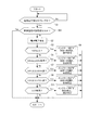
[制御回路の動作]
このような電子時計1における制御回路40の動作について、図4、5のフローチャートに基づき説明する。なお、本実施形態では、第一電圧は3.6V、第二電圧は3.4V、第三電圧は3.2Vに設定している。
[Operation of control circuit]
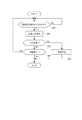
The operation of the
制御回路40は、まず電池電圧検出タイミングになったかを判定する(S1)。本実施形態では、電池電圧検出タイミングは例えば1分毎に設定されている。
S1でYesと判定されると、制御回路40は、電池電圧検出回路45を作動して二次電池24の電圧を検出する(S2)。
なお、本実施形態では、図6に示すような特性の二次電池24を用いている。図6は、電池電圧が4.2Vの場合の電池容量を100%とした場合の二次電池24の特性を示す。
First, the
If it determines with Yes by S1, the
In the present embodiment, the
制御回路40は、電池電圧検出回路45で検出した電池電圧のレベルを判定し、各レベルに応じた処理を行う。
具体的には、制御回路40は、電池電圧が4.0V以上であるかを判定し(S3)、4.0V以上であれば、残量レベルとしてFullを意味する「F」を記憶部40Aに記憶し、このデータに基づいて文字板11において「F」を指示する位置にインジケーター針61を移動する(S4)。この際、指針12は通常運針を継続する。このため、秒針121は通常の1秒運針(1秒毎にステップ駆動される運針)を継続する。また、制御回路40は、GPS受信回路30による受信を許可する。このため、予め設定された自動受信時間になった場合(自動受信処理時)や、利用者がボタン15を3秒以上押して受信開始操作を行った場合(手動受信処理時)には、制御回路40はGPS受信回路30を作動して受信処理を行う。
The
Specifically, the
S3でNoと判定された場合、制御回路40は、電池電圧が3.6V以上、4.0V未満であるかを判定する(S5)。
制御回路40は、S5でYesと判定されると、残量レベルとしてMiddleを意味する「M」を記憶部40Aに記憶し、このデータに基づいて文字板11において「M」を指示する位置にインジケーター針61を移動する(S6)。この際、指針12は通常運針(1秒運針)を継続し、かつ、GPS受信回路30による受信を許可する。このため、制御回路40は、自動受信処理や手動受信処理時に、GPS受信回路30を作動して受信処理を行う。
When it determines with No by S3, the
When it is determined Yes in S5, the
S5でNoと判定された場合、制御回路40は、電池電圧が3.4V以上、3.6V(第一電圧)未満であるかを判定する(S7)。
制御回路40は、S7でYesと判定されると、第一制御モードを実行する。すなわち、制御回路40は、残量レベルとしてEmptyを意味する「E」を記憶部40Aに記憶し、このデータに基づいて文字板11において「E」を指示する位置にインジケーター針61を移動する(S8)。また、指針12は通常運針(1秒運針)を継続するが、GPS受信回路30による受信開始(負荷の駆動開始)は禁止する。このため、制御回路40は、自動受信処理や手動受信処理が行われても、GPS受信回路30を作動することはなく、受信処理開始を禁止する。
When it determines with No by S5, the
If it is determined Yes in S7, the
S7でNoと判定された場合、制御回路40は、電池電圧が3.2V以上、3.4V(第二電圧)未満であるかを判定する(S9)。
制御回路40は、S9でYesと判定されると、第二制御モードを実行する。すなわち、制御回路40は、残量レベルとしてEmptyを意味する「E」を記憶部40Aに記憶し、このデータに基づいて文字板11において「E」を指示する位置にインジケーター針61を移動する(S10)。また、制御回路40は、秒針121を用いてBLD運針を行う。BLD運針とは、電池電圧低下表示(Battery Low Display)や、電池寿命切れ予告表示(battery life indicator)を利用者に知らせて、充電を促す機能である。このため、制御回路40は、秒針121を2秒毎に2秒分運針して、通常の1秒毎の運針とは異なる動作をさせることで、利用者にBLD表示が行われていることを通知する。
また、制御回路40は、GPS受信回路30による受信も禁止する。
When it determines with No by S7, the
If it is determined Yes in S9, the
The
S9でNoと判定された場合、制御回路40は、電池電圧が3.2V(第三電圧)未満であるかを判定する(S11)。
制御回路40は、S11でYesと判定されると、残量レベルとしてEmptyを意味する「E」を記憶部40Aに記憶し、このデータに基づいて文字板11において「E」を指示する位置にインジケーター針61を移動する(S12)。また、制御回路40は、秒針121を停止し、GPS受信回路30による受信も禁止する。
なお、S9で「No」と判断された場合は、電池電圧は3.2V未満であるはずであるから、S11の判定処理を行わずに、直接S12の処理を行ってもよい。
When it determines with No by S9, the
When it is determined Yes in S11, the
Note that if “No” is determined in S9, the battery voltage should be less than 3.2 V, so the processing in S12 may be performed directly without performing the determination processing in S11.
次に、GPS受信回路30が作動中の場合の処理に関し、図5のフローチャートに基づき説明する。
受信処理が開始されると、制御回路40は、まず、電池電圧の検出タイミングであるかを判定する(S21)。本実施形態では、受信中の電池電圧検出タイミングは、受信中でない場合の1分間隔よりも短い1秒間隔に設定されている。
制御回路40は、S21でYesと判定すると、1秒毎に電池電圧検出回路45を作動して二次電池24の電圧を検出する(S22)。
Next, processing when the
When the reception process is started, the
If it determines with Yes by S21, the
そして、制御回路40は、検出した電池電圧が第三電圧(本実施形態では3.2V)未満であるかを判定する(S23)。電池電圧が第三電圧以上であり、S23でNoと判定されると、制御回路40は受信処理が終了したかを判定する(S24)。
制御回路40は、必要なデータを受信した場合や、受信開始から設定時間経過した場合は、S24で受信終了と判定する。一方、制御回路40は、S24で受信終了ではないと判定した場合は、S21に戻って処理を継続する。
Then, the
When the necessary data is received or when the set time has elapsed from the start of reception, the
制御回路40は、S23で電池電圧が第三電圧未満の場合(S23でYesと判定された場合)、受信処理を中止する(S25)。
そして、制御回路40は、S25で受信処理を中止した場合や、S24で受信終了と判定した場合、図5の処理を終了する。
なお、GPS受信回路30が作動中は、図5の処理のみが行われ、図4の処理は実行されない。このため、GPS受信回路30の動作中は残量表示手段60による残量レベルの表示処理も更新されない。
If the battery voltage is less than the third voltage in S23 (if determined Yes in S23), the
Then, the
Note that while the
以上の各電池電圧レベルにおける電池容量、インジケーター針61の指示(残量レベル)、秒針121の運針制御、持続日数の関係を図7に示す。ここで、持続日数は、二次電池24の電圧に対して、受信処理を行わなかった場合の電子時計1が作動する持続時間(日数)である。
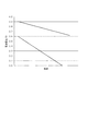
また、図8は、受信開始時から終了時までの電池電圧の変化を示す。この図8に示すように、電池電圧が第一電圧である3.6Vより低い電圧で受信を行うと、内部インピーダンスが上昇して受信電流により電池電圧が受信動作に必要な第三電圧(例えば3.2V)以下に低下する。このように、電池電圧が3.6V以下の状態で受信処理を行うと、負荷であるGPS受信回路30を作動させるのに必要な電圧(3.2V)を下回るため、受信ができなくなる。このため、電池電圧が3.6V以下の状態では受信処理を実行しないように制限する必要がある。
一方、電池電圧が第一電圧以上、例えば3.9V程度あれば、受信処理で電池電圧が低下しても、受信するのに必要な電圧(3.2V)を下回ることがないため、受信を制限する必要は無い。
FIG. 7 shows the relationship between the battery capacity, the
FIG. 8 shows a change in battery voltage from the start to the end of reception. As shown in FIG. 8, when the battery voltage is received at a voltage lower than the first voltage of 3.6 V, the internal impedance rises and the received voltage causes the battery voltage to be a third voltage required for the receiving operation (for example, 3.2V) Decrease to below. As described above, when the reception process is performed in a state where the battery voltage is 3.6 V or lower, the voltage is lower than the voltage (3.2 V) necessary for operating the
On the other hand, if the battery voltage is equal to or higher than the first voltage, for example, about 3.9V, even if the battery voltage decreases in the reception process, the voltage required for reception (3.2V) will not fall below. There is no need to limit.
従って、図4や図7に示すように、電池電圧が4.0V以上であれば、十分に受信可能な状態であるので、インジケーター針61は残量レベルとして「F」を示し、通常運針(1秒運針)を継続し、受信処理も制限されない。
電池電圧が3.6V以上、4.0V未満の時は、電池容量は多少減少するため、インジケーター針61は残量レベルとして「M」を示すが、通常運針(1秒運針)を継続し、受信処理も制限されない。すなわち、電子時計1の動作は制限しないが、インジケーター針61で「M」を指示することで、電池電圧が低下して「E」状態、つまり受信が制限される状態に近づいていることを利用者に告知し、二次電池24への充電を促す。電子時計1は、ソーラーセル22を備えているので、利用者がソーラーセル22に光を照射することで、二次電池24への充電を行うことができる。
Therefore, as shown in FIG. 4 and FIG. 7, if the battery voltage is 4.0 V or higher, the battery is sufficiently receivable. Therefore, the
When the battery voltage is 3.6V or more and less than 4.0V, the battery capacity is slightly reduced. Therefore, the
電池電圧が第一電圧である3.6V未満であると、前述したように第一制御モードが実行されて受信処理を開始できないので、インジケーター針61は残量レベルとして「E」を指示する。このため、制御回路40は、ボタン15が押されても強制受信処理を行わず、また、自動受信処理時間になっても自動受信処理を行わない。
一方で、電池電圧が3.6V未満であっても、第二電圧である3.4V以上であれば、持続日数は65日と十分な期間、時計として機能する。この65日の期間は、受信機能以外の通常の時計としての機能は十分に利用できるので、秒針121を2秒運針させて通常と異なる動作をさせるのは無駄である。従って、制御回路40は、秒針121の1秒運針を継続する。
If the battery voltage is less than the first voltage of 3.6 V, the first control mode is executed as described above, and the reception process cannot be started. Therefore, the
On the other hand, even if the battery voltage is less than 3.6V, if the second voltage is 3.4V or more, the duration of the battery functions as a clock for a sufficient period of 65 days. During this period of 65 days, functions as a normal clock other than the reception function can be fully utilized, so it is useless to operate the
また、電池電圧が第二電圧である3.4V未満になると、時計として機能できる日数が減ってくるので、制御回路40は、秒針121を2秒運針(BLD運針)にし、利用者に電池電圧が低下していることを通知し、ソーラーセル22に即座に光に当てて充電することを促す。
Further, when the battery voltage becomes less than 3.4 V, which is the second voltage, the number of days that can function as a clock decreases. Therefore, the
[第1実施形態の作用効果]
このような第1実施形態によれば、以下の作用効果が得られる。
制御回路40は、一定周期で電池電圧検出回路45を作動して二次電池24の電池電圧を検出し、二次電池24の電池電圧が第一電圧(本実施形態では3.6V)未満に低下すると、インジケーター針61で「E」を指示させ、かつ、受信動作を禁止する。このため、電池電圧が第一電圧未満に低下した状態で受信動作が開始されることがないため、受信動作中に電池電圧が低下して受信処理を中止しなければならない状態を未然に回避できる。このため、受信処理のために無駄に電力を消費することもなく、二次電池24を有効に活用でき、持続時間も長くできる。
[Effects of First Embodiment]
According to such 1st Embodiment, the following effects are obtained.
The
また、制御回路40は、二次電池24の電池電圧が第二電圧(本実施形態では3.4V)未満に低下すると、秒針121を2秒運針させてBLD表示を行う。このため、利用者に電池電圧が低下していることを通知でき、ソーラーセル22による充電を促すことができる。従って、電池電圧が更に低下して3.2V未満になり、運針を停止しなければならない状態になることを容易に防止できる。
Further, when the battery voltage of the
さらに、制御回路40は、インジケーター針61によって、電池電圧が第一電圧未満で受信動作を禁止している状態(「E」)を通知し、秒針121でBLD状態を通知している。このように、インジケーター針61および秒針121を用いて、2つの状態を通知しているので、利用者は現在の状況を把握しやすく、電子時計1の使い勝手を向上できる。
Further, the
また、制御回路40は、二次電池24の電池電圧が第一電圧未満、第二電圧以上の状態では、受信動作は禁止するが、通常の1秒運針を継続している。このため、受信動作の禁止と同時にBLD表示用の運針を行う場合や、BLD表示用の運針を行ってからさらに電池電圧が低下した場合に受信動作を禁止する場合に比べて、時計として利用できる期間を長くできる。この点でも、電子時計1の使い勝手を向上できる。
In addition, the
さらに、秒針121を用いてBLD表示を行っているので、利用者は電池電圧が低下していることを容易に確認できる。また、秒針121は独立したモーターで駆動される場合が多いため、1秒運針と2秒運針の切替も容易に行うことができる。
Furthermore, since the BLD display is performed using the
[第2実施形態]
次に本発明の第2実施形態について、図9,10を参照して説明する。
第2実施形態は、制御回路40による電池電圧の検出タイミングを、充電状態(発電状態)であるか否かで変更するものであり、それ以降の処理は前記第1実施形態と同一である。従って、図9のフローチャートにおいて、前記図4のフローチャートと同じ処理には同一の符号を付して説明を省略する。
[Second Embodiment]
Next, a second embodiment of the present invention will be described with reference to FIGS.
In the second embodiment, the detection timing of the battery voltage by the
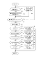
第2実施形態の制御回路40は、まず充電状態であるかを判定する(S31)。具体的には、図10に示すように、制御回路40は、1秒間隔の制御信号を出力し、発電状態検出回路43を1秒毎に作動する。
制御信号が入力されると、発電状態検出回路43は、充電状態(発電状態)であるか否かを示す検出結果を制御回路40に出力する。このため、制御回路40は、充電状態であるか否かを判定する(S31)。
The
When the control signal is input, the power generation
制御回路40は、S31でNoと判定された場合つまり非充電状態中は、電池電圧検出タイミングを、例えば1分間隔に設定する(S32)。一方、制御回路40は、S31でYesと判定された場合つまり充電状態中は、電池電圧検出タイミングを、例えば2分間隔に設定する(S33)。
そして、制御回路40は、S32,33で設定した電池電圧検出タイミングでS1の判定処理を行う。S1でYesと判定された後のS2〜S12の処理は前記第1実施形態と同じである。
なお、本実施形態において、S1の電池電圧検出タイミングは、図10に示すように、S31の充電状態の検出タイミングと同じでもよいし、異なるタイミングで検出してもよい。さらに、S32,33の検出間隔は、1分、2分に限定されず、充電手段の種類などに応じて適宜設定すればよい。
When it is determined No in S31, that is, during the non-charge state, the
Then, the
In this embodiment, the battery voltage detection timing of S1 may be the same as the detection timing of the state of charge of S31 or may be detected at a different timing as shown in FIG. Furthermore, the detection intervals of S32 and 33 are not limited to 1 minute and 2 minutes, and may be set as appropriate according to the type of charging means.
[第2実施形態の作用効果]
このような第2実施形態によれば、第1実施形態と同じ作用効果が得られる上、充電状態の場合には、電池電圧検出タイミングを2分と通常のタイミングの2倍の間隔に長くしているので、S2〜S12のインジケーター針61の表示更新間隔や、秒針121の運針制御、受信制御の更新間隔を長くすることができる。
ここで、充電中は、二次電池24の内部抵抗によって、電池電圧検出回路45で検出される電池電圧が一時的に高くなる。このため、実際の電圧よりも検出電圧が高くなり、このような見かけの電池電圧によって、S3〜S12の処理を行うと、実際の電池容量等と、インジケーター針61の表示等がずれてしまう。
一方、本実施形態のように、充電中の電池電圧検出タイミングの間隔を長くすれば、インジケーター針61の表示等が更新されるまでの時間が長くなり、その間、二次電池24が充電される時間も長くできる。従って、インジケーター針61の表示などと、実際の電池容量との誤差を小さくでき、各制御モードを適切に実行できる。
[Effects of Second Embodiment]
According to the second embodiment as described above, the same operational effects as the first embodiment can be obtained, and in the charged state, the battery voltage detection timing is increased to 2 minutes and twice the normal timing. Therefore, the display update interval of the indicator hands 61 of S2 to S12 and the update interval of the hand movement control and reception control of the
Here, during charging, the battery voltage detected by the battery
On the other hand, if the interval of the battery voltage detection timing during charging is increased as in this embodiment, the time until the display of the
[第3実施形態]
次に本発明の第3実施形態について、図11のフローチャートを参照して説明する。なお、第3実施形態の処理において、前記第1、2実施形態と同じ処理には同一の符号を付して説明を省略する。
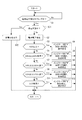
第3実施形態では、図11に示すように、制御回路40は、電池電圧検出タイミングの判定(S1)で「Yes」と判定された後、充電状態であるかを判定する(S31)。この充電状態の判定処理(S31)は、第2実施形態と同じ処理である。
[Third Embodiment]
Next, a third embodiment of the present invention will be described with reference to the flowchart of FIG. In the process of the third embodiment, the same processes as those of the first and second embodiments are denoted by the same reference numerals and the description thereof is omitted.
In the third embodiment, as shown in FIG. 11, the
そして、制御回路40は、S31でYesと判定した場合、S2〜S12の処理は実行せずに、充電中であることを表示する(S32)。充電中であることを表示する方法は、例えば、インジケーター針61を「F、M、E」のいずれも指示しない場所に移動し、電池容量の残量を表示しないことで充電中であることを表示すればよい。あるいは、「充電中」を示す目盛を追加してインジケーター針61で指示してもよい。
If the
一方、制御回路40は、S31でNoと判定した場合、第1、2実施形態と同じくS2〜S12の処理を行う。
なお、本実施形態においても、S1の電池電圧検出タイミングと、S31の充電状態の検出タイミングとは同じでもよいし、異なるタイミングでもよい。
On the other hand, when it is determined No in S31, the
Also in this embodiment, the battery voltage detection timing in S1 and the charge state detection timing in S31 may be the same or different.
[第3実施形態の作用効果]
このような第3実施形態によれば、第1実施形態と同じ作用効果が得られる上、充電状態中は、充電中を表示し(S32)、S2〜S12の処理を行わない。このため、充電中に、二次電池24の内部抵抗によって、電池電圧検出回路45で検出される電池電圧が一時的に高くなることで、実際の電池容量等と、インジケーター針61の表示等がずれてしまうことを防止できる。S2〜S12の処理は、充電状態でなくなった時点で行われるので、充電後の実際の電池電圧に基づいて各制御モードを適切に実行できる。
[Effects of Third Embodiment]
According to such a 3rd embodiment, while being able to obtain the same operation effect as a 1st embodiment, during charge, charging is displayed (S32) and processing of S2-S12 is not performed. For this reason, during charging, the battery voltage detected by the battery
[第4実施形態]
次に本発明の第4実施形態について、図12のフローチャートを参照して説明する。なお、第4実施形態の処理において、前記第1〜3実施形態と同じ処理には同一の符号を付して説明を省略する。
第4実施形態では、図12に示すように、制御回路40は、電池電圧検出タイミングの判定(S1)で「Yes」と判定された後、開放電圧が設定値以上であるかを判定する(S41)。
[Fourth Embodiment]
Next, a fourth embodiment of the present invention will be described with reference to the flowchart of FIG. In the process of the fourth embodiment, the same processes as those of the first to third embodiments are denoted by the same reference numerals and the description thereof is omitted.
In the fourth embodiment, as shown in FIG. 12, the
S41では、制御回路40は、充電制御用スイッチ42をオフ状態に切り替えて、開放電圧検出回路44を作動して開放電圧を検出し、その値が設定値以上であるかを判定する。ここで、充電制御用スイッチ42をオフ状態にしているので、ソーラーセル22および開放電圧検出回路44は、二次電池24とは切り離される。このため、開放電圧検出回路44は、二次電池24の充電電圧の影響を受けることなく、ソーラーセル22に当たる光の照度に対応する開放電圧を検出できる。
この開放電圧は、ソーラーセル22における照度が高くなるほど高くなる。また、ソーラーセル22は、当たっている照度つまり開放電圧が高いほど、充電電流も多くなる。そして、充電電流が多くなると、二次電池24における見かけの電圧が高くなる。この状態、S2〜S12の処理を行うと、二次電池24の実際の電池電圧とインジケーター針61の指示等が相違する可能性がある。
In S41, the
The open circuit voltage increases as the illuminance in the
そこで、本実施形態では、S41でYesと判定された場合は、S2〜S12の処理を行わないように制御している。
なお、前記開放電圧の設定値(閾値)は、充電電流が多くなるレベル、例えば、電子時計1に太陽光が照射している状態であるか否かを判定できるレベルなどに設定すればよい。
また、開放電圧の検出時には、充電制御用スイッチ42をオフするため、二次電池24に充電することができない。このため、開放電圧の検出を、電池電圧検出タイミングに合わせて間欠的に行うことが好ましい。
Therefore, in this embodiment, when it is determined Yes in S41, control is performed so as not to perform the processes of S2 to S12.
The set value (threshold value) of the open-circuit voltage may be set to a level at which the charging current increases, for example, a level at which it can be determined whether or not the
In addition, when the open circuit voltage is detected, the
一方、制御回路40は、S41でNoと判定した場合、第1〜3実施形態と同じくS2〜S12の処理を行う。
On the other hand, when it is determined No in S41, the
[第4実施形態の作用効果]
このような第4実施形態によれば、第1実施形態と同じ作用効果が得られる上、開放電圧が設定値以上の場合は、S2〜S12の処理を行わない。このため、ソーラーセル22に当たっている照度が高く、充電電流が多くなって電池電圧検出回路45で検出される電池電圧が一時的に高くなることで、実際の電池容量等と、インジケーター針61の表示等がずれてしまうことを防止できる。S2〜S12の処理は、開放電圧が設定値未満になった時点で行われるので、充電後の実際の電池電圧に基づいて各制御モードを適切に実行できる。
[Effects of Fourth Embodiment]
According to such 4th Embodiment, the same effect as 1st Embodiment is acquired, and when an open circuit voltage is more than a setting value, the process of S2-S12 is not performed. For this reason, the illuminance hitting the
[第5実施形態]
次に本発明の第5実施形態について、図13を参照して説明する。
第5実施形態の電子時計1Aは、前記実施形態のインジケーター針61を無くし、秒針121をインジケーター針として兼用したものである。このため、電子時計1Aでは、たとえば、ボタン16を所定時間以上押すと、秒針121がインジケーター針として動作し、記憶部40Aに記憶された最新の残量レベル(電池電圧検出結果)に基づき、「F,M,E」のいずれかを指示する。図13では、文字板11の56秒位置に「F」、53秒位置に「M」、50秒位置に「E」が表示されており、インジケーター針である秒針121によって、電池容量の残量レベルをインジケーター表示する。
[Fifth Embodiment]
Next, a fifth embodiment of the present invention will be described with reference to FIG.
An
このように第5実施形態は、インジケーター針を秒針121で兼用した点が前記実施形態と相違する。従って、電池電圧の検出処理方法は、第1〜4実施形態のいずれを適用してもよい。
As described above, the fifth embodiment is different from the above embodiment in that the indicator hand is also used as the
[第5実施形態の作用効果]
このような第5実施形態によれば、インジケーター針61を無くして、秒針121で兼用できるので、インジケーター針61やこのインジケーター針61を駆動するモーター、輪列を不要にできる。このため、部品点数を少なくできてコストを低減できる。
[Effects of Fifth Embodiment]
According to the fifth embodiment, since the
[第6実施形態]
次に本発明の第6実施形態について、図14を参照して説明する。
第6実施形態の電子時計1Bは、曜日を指示する曜日針125を備えるものであり、この曜日針125をインジケーター針として兼用したものである。このため、電子時計1Bでは、文字板11に、曜日針125で指示される曜日が半円部分に沿って表示されている。
また、この曜日表示に隣接してインジケーター表示用の「F,M,E」も表示されている。具体的には、文字板11の「Sun」の位置に「F」、「Thu」の位置に「M」、「Mon」の位置に「E」が表示されている。
[Sixth Embodiment]
Next, a sixth embodiment of the present invention will be described with reference to FIG.
An
Further, “F, M, E” for indicator display is also displayed adjacent to the day display. Specifically, “F” is displayed at the “Sun” position on the
そして、電子時計1Bでは、たとえば、ボタン16を所定時間以上押すと、通常時は曜日を指示する曜日針125がインジケーター針として動作し、記憶部40Aに記憶された最新の残量レベル(電池電圧検出結果)に基づき、「F,M,E」のいずれかを指示する。
In the
このように第6実施形態は、インジケーター針を曜日針125で兼用した点が前記実施形態と相違する。従って、電池電圧の検出処理方法は、第1〜4実施形態のいずれを適用してもよい。
As described above, the sixth embodiment is different from the above-described embodiment in that the indicator hand is also used as the
[第6実施形態の作用効果]
このような第6実施形態によれば、インジケーター針61を無くして、曜日針125で兼用できるので、曜日針125とは別にインジケーター針61を設ける場合に比べて、部品点数を少なくできてコストを低減できる。
[Effects of Sixth Embodiment]
According to the sixth embodiment, since the
[第7実施形態]
次に本発明の第7実施形態について、図15を参照して説明する。
第7実施形態の電子時計1Cは、インジケーター針61Aを備え、このインジケーター針61Aが、電池残量を表示する残量表示手段60と予告表示手段70とを兼用している点が前記各実施形態と異なる。
すなわち、インジケーター針61Aは、電池残量を表示するための「F,M」の他に、「E1、E2」を指示する。「E1」は、前記各実施形態の「E」と同様に、電池残量(電圧)が低下しており、受信動作の開始を禁止する第一制御モードを実行している場合に指示される。
一方、「E2」は、さらに電池残量(電圧)が低下して、計時機構の停止が近づいていることを予告する第二制御モードを実行している場合に指示される。
[Seventh Embodiment]
Next, a seventh embodiment of the present invention will be described with reference to FIG.
The
That is, the
On the other hand, “E2” is instructed when the second control mode in which the remaining battery level (voltage) further decreases and the time measuring mechanism is approaching to stop is being executed.
このように第7実施形態は、インジケーター針61Aを、残量表示手段60として利用するだけでなく、予告表示手段70としても利用する点が、予告表示手段として秒針121を用いていた前記各実施形態と相違する。従って、電池電圧の検出処理方法は、第1〜4実施形態のいずれを適用してもよい。
Thus, the seventh embodiment uses the
[第7実施形態の作用効果]
このような第7実施形態によれば、インジケーター針61Aを、残量表示手段60および予告表示手段70として兼用しているので、利用者はインジケーター針61Aの指示のみをチェックすれば、現在第一制御モードであるか、第二制御モードであるかを確認できる。
また、第二制御モードの特殊な運針で秒針121を作動させる必要が無く、秒針121の制御を容易に行うことができる。
[Effects of Seventh Embodiment]
According to the seventh embodiment, since the
Further, there is no need to operate the
[他の実施形態]
なお、本発明は前記実施形態の構成に限定されず、本発明の要旨の範囲内で種々の変形
実施が可能である。
[Other Embodiments]
In addition, this invention is not limited to the structure of the said embodiment, A various deformation | transformation implementation is possible within the range of the summary of this invention.
例えば、前記各実施形態は、時刻表示手段52として指針12を用いたアナログ式の電子時計であったが、液晶ディスプレイなどを用いて時刻を表示するデジタル式の電子時計としてもよい。
また、充電手段としては、ソーラーセル22に限定されず、回転錘などを用いて発電する発電機を用いてもよい。また、電源コードを用いて外部電源(商用コンセントなど)から充電するものでもよいし、電磁誘導などを利用した非接触充電によって外部電源から充電するものでもよい。
For example, each embodiment described above is an analog electronic timepiece that uses the
Further, the charging means is not limited to the
前記実施形態の残量表示手段60は、電池残量をF、M、Eの三段階で表示していたが、第一電圧以上であるか未満であるかを、例えば、「F」と「E」との2段階で表示してもよい。一方で、残量表示手段60は、電池残量を四段階以上で表示してもよい。例えば、インジケーター針61によって、電池残量を0〜100%まで1%毎に表示してもよい。
予告表示手段70は、秒針121を2秒運針するものに限定されず、例えば一定範囲で秒針121を往復運針するものなど、通常運針と異なる表示を行うものであればよい。
The remaining amount display means 60 of the above embodiment displays the remaining battery level in three stages of F, M, and E. For example, “F” and “ E ”may be displayed in two stages. On the other hand, the remaining amount display means 60 may display the remaining battery level in four or more stages. For example, the remaining battery level may be displayed from 0 to 100% by the
The notice display means 70 is not limited to the one that moves the
前記各実施形態では、電池電圧のレベルを判定する際に、S3〜S11まで閾値と順次比較することで判定していたが、電池電圧検出回路45の検出値をADコンバーターを介して数値化して直接判定してもよい。
In each of the above embodiments, when determining the level of the battery voltage, the determination is made by sequentially comparing the threshold values from S3 to S11. However, the detection value of the battery
本発明の電子時計1は、腕時計に限定されず、電子時計機能を有する各種の装置に広く適用できる。特に、二次電池で駆動される携帯型の電子時計に適している。
The
1,1A,1B,1C…電子時計、12…指針、15,16…ボタン、21…ムーブメント、22…ソーラーセル、23…GPSアンテナ、24…二次電池、30…GPS受信回路、40…制御回路、40A…記憶部、42…充電制御用スイッチ、43…発電状態検出回路、44…開放電圧検出回路、45…電池電圧検出回路、51…計時手段、52…時刻表示手段、60…残量表示手段、61,61A…インジケーター針、70…予告表示手段、121…秒針、125…曜日針。
DESCRIPTION OF
Claims (10)
前記二次電池に電力を充電する充電手段と、
前記二次電池の電力で駆動されて時刻を計時する計時手段と、
前記二次電池の電力で駆動されて前記時刻を表示する時刻表示手段と、
前記計時手段および前記時刻表示手段以外の前記二次電池の電力で駆動される負荷と、
前記二次電池の電圧を検出する電池電圧検出手段と、
前記二次電池の電圧が第一電圧未満に低下した場合は、前記負荷の駆動開始を禁止し、かつ、前記計時手段および前記時刻表示手段の駆動は禁止しない第一制御モードを実行し、
前記二次電池の電圧が前記第一電圧よりも低い第二電圧未満に低下した場合は、前記計時手段の停止が近づいていることを予告する第二制御モードを実行する制御手段と、を備える
ことを特徴とする電子時計。 A secondary battery,
Charging means for charging the secondary battery with power;
A time measuring means for measuring time driven by the power of the secondary battery;
Time display means driven by the power of the secondary battery to display the time;
And load that will be driven by the power of the secondary battery other than the time measuring means and the time display means,
Battery voltage detection means for detecting the voltage of the secondary battery;
When the voltage of the secondary battery has dropped below the first voltage, execute the first control mode that prohibits the driving start of the load and does not prohibit the driving of the time measuring means and the time display means ,
Control means for executing a second control mode for notifying that the stop of the time measuring means is approaching when the voltage of the secondary battery drops below a second voltage lower than the first voltage. An electronic timepiece characterized by that.
前記二次電池の電池残量を表示する残量表示手段と、
前記計時手段の停止を予告する予告表示手段と、を備え、
前記時刻表示手段は秒針を備え、
前記残量表示手段は、前記第一制御モードが実行された場合は、前記秒針とは別の指針を、電池残量を表示するインジケーター針として用い、
前記予告表示手段は、前記第二制御モードが実行された場合は、前記秒針を通常の運針と異なる運針で作動させる
ことを特徴とする電子時計。 The electronic timepiece according to claim 1,
A remaining amount display means for displaying a remaining battery level of the secondary battery;
A notice display means for notifying the stop of the time measuring means,
The time display means includes a second hand,
When the first control mode is executed, the remaining amount display means uses a pointer different from the second hand as an indicator hand for displaying the remaining battery level,
When the second control mode is executed, the notice display means operates the second hand with a different hand movement from a normal hand movement.
前記二次電池の電池残量を表示する残量表示手段と、
前記計時手段の停止を予告する予告表示手段と、を備え、
前記時刻表示手段は秒針を備え、
前記残量表示手段は、前記第一制御モードが実行された場合は、前記秒針を、電池残量を表示するインジケーター針として用い、
前記予告表示手段は、前記第二制御モードが実行された場合は、前記秒針を通常の運針と異なる運針で作動させる
ことを特徴とする電子時計。 The electronic timepiece according to claim 1,
A remaining amount display means for displaying a remaining battery level of the secondary battery;
A notice display means for notifying the stop of the time measuring means,
The time display means includes a second hand,
When the first control mode is executed, the remaining amount display means uses the second hand as an indicator hand for displaying a battery remaining amount,
When the second control mode is executed, the notice display means operates the second hand with a different hand movement from a normal hand movement.
前記二次電池の残量レベルを記憶する記憶部と、
ボタンと、を備え、
前記制御手段は、前記第一制御モードの実行時に前記ボタンが押されると前記残量表示手段を作動し、前記記憶部に記憶されたデータに基づいて電池残量を表示する
ことを特徴とする電子時計。 The electronic timepiece according to claim 2 or 3,
A storage unit for storing a remaining battery level of the secondary battery;
And a button,
The control unit operates the remaining amount display unit when the button is pressed during execution of the first control mode, and displays the remaining battery level based on data stored in the storage unit. Electronic clock.
前記制御手段は、前記負荷の動作中は、前記残量表示手段による電池残量の表示を更新しない
ことを特徴とする電子時計。 The electronic timepiece according to any one of claims 2 to 4,
The electronic timepiece characterized in that the control means does not update the battery remaining amount display by the remaining amount display means during operation of the load.
前記制御手段は、前記負荷の動作中における前記電池電圧検出手段による電池電圧の検出間隔を、前記負荷が動作していない場合の検出間隔に比べて短くする
ことを特徴とする電子時計。 The electronic timepiece according to any one of claims 1 to 5,
The electronic timepiece characterized in that the control means makes the battery voltage detection interval by the battery voltage detection means during operation of the load shorter than the detection interval when the load is not operating.
前記制御手段は、前記負荷の動作中に前記電池電圧検出手段で検出した前記二次電池の電圧が、前記第一電圧よりも低い第三電圧未満に低下した場合は、前記負荷の動作を停止する
ことを特徴とする電子時計。 The electronic timepiece according to any one of claims 1 to 6,
The control means stops the operation of the load when the voltage of the secondary battery detected by the battery voltage detection means during operation of the load falls below a third voltage lower than the first voltage. An electronic watch characterized by
前記充電手段が前記二次電池に電力を充電している充電状態であるか、あるいは、非充電状態であるかを検出する充電状態検出手段を備え、
前記制御手段は、前記充電手段が充電状態の場合は、前記電池電圧検出手段による電池電圧の検出間隔を、非充電状態の場合に比べて長くする
ことを特徴とする電子時計。 The electronic timepiece according to any one of claims 1 to 7,
A charging state detecting means for detecting whether the charging means is in a charging state in which the secondary battery is charged with power or in a non-charging state;
The electronic timepiece characterized in that when the charging means is in a charged state, the control means makes the battery voltage detection interval by the battery voltage detecting means longer than that in a non-charged state.
前記充電手段が前記二次電池に電力を充電している充電状態であるか、あるいは、非充電状態であるかを検出する充電状態検出手段を備え、
前記制御手段は、前記充電手段が充電状態の場合は、前記電池電圧検出手段による電池電圧の検出動作を停止する
ことを特徴とする電子時計。 The electronic timepiece according to any one of claims 1 to 7,
A charging state detecting means for detecting whether the charging means is in a charging state in which the secondary battery is charged with power or in a non-charging state;
The electronic timepiece characterized in that the control means stops the battery voltage detection operation by the battery voltage detection means when the charging means is in a charged state.
前記充電手段は、ソーラーセルを備えて構成され、
前記ソーラーセルの開放電圧を検出する開放電圧検出手段を備え、
前記制御手段は、前記開放電圧が設定値以上の場合は、前記電池電圧検出手段による電池電圧の検出動作を停止する
ことを特徴とする電子時計。 The electronic timepiece according to any one of claims 1 to 7,
The charging means includes a solar cell,
Comprising an open voltage detection means for detecting an open voltage of the solar cell;
The control unit stops the battery voltage detection operation by the battery voltage detection unit when the open voltage is equal to or higher than a set value.
Priority Applications (1)
| Application Number | Priority Date | Filing Date | Title |
|---|---|---|---|
| JP2012047251A JP6010930B2 (en) | 2012-03-02 | 2012-03-02 | Electronic clock |
Applications Claiming Priority (1)
| Application Number | Priority Date | Filing Date | Title |
|---|---|---|---|
| JP2012047251A JP6010930B2 (en) | 2012-03-02 | 2012-03-02 | Electronic clock |
Related Child Applications (1)
| Application Number | Title | Priority Date | Filing Date |
|---|---|---|---|
| JP2015063190A Division JP6164240B2 (en) | 2015-03-25 | 2015-03-25 | Electronic clock |
Publications (3)
| Publication Number | Publication Date |
|---|---|
| JP2013181915A JP2013181915A (en) | 2013-09-12 |
| JP2013181915A5 JP2013181915A5 (en) | 2015-02-26 |
| JP6010930B2 true JP6010930B2 (en) | 2016-10-19 |
Family
ID=49272647
Family Applications (1)
| Application Number | Title | Priority Date | Filing Date |
|---|---|---|---|
| JP2012047251A Active JP6010930B2 (en) | 2012-03-02 | 2012-03-02 | Electronic clock |
Country Status (1)
| Country | Link |
|---|---|
| JP (1) | JP6010930B2 (en) |
Families Citing this family (9)
| Publication number | Priority date | Publication date | Assignee | Title |
|---|---|---|---|---|
| JP5946067B2 (en) * | 2013-05-22 | 2016-07-05 | 国立研究開発法人防災科学技術研究所 | Measurement seismic intensity estimation device and measurement seismic intensity estimation system using the same |
| JP6398234B2 (en) | 2014-03-07 | 2018-10-03 | セイコーエプソン株式会社 | Satellite signal receiving apparatus, electronic timepiece, and satellite signal receiving method |
| JP6458941B2 (en) * | 2015-02-27 | 2019-01-30 | セイコーエプソン株式会社 | Electronic clock |
| JP6459647B2 (en) * | 2015-03-06 | 2019-01-30 | セイコーエプソン株式会社 | Electronic timepiece and control method of electronic timepiece |
| JP6733380B2 (en) * | 2016-07-15 | 2020-07-29 | セイコーエプソン株式会社 | Electronic timepiece and electronic timepiece control method |
| JP6686934B2 (en) | 2017-02-27 | 2020-04-22 | カシオ計算機株式会社 | Electronic clock, display control method and program |
| JP7024283B2 (en) | 2017-09-26 | 2022-02-24 | カシオ計算機株式会社 | Radio-controlled clocks, control methods and programs for radio-controlled clocks |
| JP6729616B2 (en) | 2018-03-08 | 2020-07-22 | カシオ計算機株式会社 | Electronic device, power feeding control method, and program |
| JP7143708B2 (en) * | 2018-09-28 | 2022-09-29 | セイコーエプソン株式会社 | electronic clock |
Family Cites Families (3)
| Publication number | Priority date | Publication date | Assignee | Title |
|---|---|---|---|---|
| JP3629374B2 (en) * | 1998-11-12 | 2005-03-16 | セイコーインスツル株式会社 | Analog electronic watch with remaining capacity meter |
| JP2005308396A (en) * | 2004-04-16 | 2005-11-04 | Seiko Epson Corp | Electronic timepiece, control method of the same, program and recording medium |
| JP5294621B2 (en) * | 2007-12-28 | 2013-09-18 | シチズン時計株式会社 | Electronics |
-
2012
- 2012-03-02 JP JP2012047251A patent/JP6010930B2/en active Active
Also Published As
| Publication number | Publication date |
|---|---|
| JP2013181915A (en) | 2013-09-12 |
Similar Documents
| Publication | Publication Date | Title |
|---|---|---|
| JP6164240B2 (en) | Electronic clock | |
| JP6010930B2 (en) | Electronic clock | |
| JP5796415B2 (en) | Satellite signal receiver and electronic device | |
| JP5915030B2 (en) | Satellite signal receiving apparatus, satellite signal receiving method, and electronic device | |
| JP3596464B2 (en) | Timing device and control method of timing device | |
| JP6458941B2 (en) | Electronic clock | |
| EP2479623B1 (en) | Satellite signal receiving device, method of controlling satellite signal receiving device, and electronic device | |
| CN110635550B (en) | Electronic device, electronic timepiece, and battery charging method | |
| JP2015175602A (en) | Electronic apparatus | |
| JP6428861B2 (en) | Electronic clock | |
| JPH11223684A (en) | Radio wave corrected timepiece | |
| JP2012026774A (en) | Electronic apparatus | |
| JP5310578B2 (en) | Electronic equipment with power generation function | |
| JP5803436B2 (en) | Satellite signal receiving apparatus, satellite signal receiving method, and electronic device | |
| JP6204855B2 (en) | Electronics | |
| JP5710139B2 (en) | Satellite radio watch | |
| JP5365549B2 (en) | Satellite signal receiving device and control method of satellite signal receiving device | |
| JP5699625B2 (en) | Satellite signal receiving apparatus, satellite signal receiving apparatus control method, and electronic apparatus | |
| JP6233367B2 (en) | Electronic clock | |
| JP5703772B2 (en) | Satellite signal receiving apparatus, satellite signal receiving apparatus control method, and electronic apparatus | |
| JP6546038B2 (en) | Electronic clock and control method of electronic clock | |
| JP5946554B2 (en) | Satellite radio watch | |
| JP5987596B2 (en) | Electronic clock | |
| JP6048118B2 (en) | Portable electronic devices with power generation function | |
| JP7075828B2 (en) | Electronic clock |
Legal Events
| Date | Code | Title | Description |
|---|---|---|---|
| A521 | Written amendment |
Free format text: JAPANESE INTERMEDIATE CODE: A523 Effective date: 20150113 |
|
| A621 | Written request for application examination |
Free format text: JAPANESE INTERMEDIATE CODE: A621 Effective date: 20150113 |
|
| A977 | Report on retrieval |
Free format text: JAPANESE INTERMEDIATE CODE: A971007 Effective date: 20151130 |
|
| A131 | Notification of reasons for refusal |
Free format text: JAPANESE INTERMEDIATE CODE: A131 Effective date: 20160112 |
|
| A521 | Written amendment |
Free format text: JAPANESE INTERMEDIATE CODE: A523 Effective date: 20160310 |
|
| TRDD | Decision of grant or rejection written | ||
| A01 | Written decision to grant a patent or to grant a registration (utility model) |
Free format text: JAPANESE INTERMEDIATE CODE: A01 Effective date: 20160823 |
|
| A61 | First payment of annual fees (during grant procedure) |
Free format text: JAPANESE INTERMEDIATE CODE: A61 Effective date: 20160905 |
|
| R150 | Certificate of patent (=grant) or registration of utility model |
Ref document number: 6010930 Country of ref document: JP Free format text: JAPANESE INTERMEDIATE CODE: R150 |