JP5703772B2 - Satellite signal receiving apparatus, satellite signal receiving apparatus control method, and electronic apparatus - Google Patents
Satellite signal receiving apparatus, satellite signal receiving apparatus control method, and electronic apparatus Download PDFInfo
- Publication number
- JP5703772B2 JP5703772B2 JP2011009925A JP2011009925A JP5703772B2 JP 5703772 B2 JP5703772 B2 JP 5703772B2 JP 2011009925 A JP2011009925 A JP 2011009925A JP 2011009925 A JP2011009925 A JP 2011009925A JP 5703772 B2 JP5703772 B2 JP 5703772B2
- Authority
- JP
- Japan
- Prior art keywords
- power generation
- circuit
- satellite signal
- solar cell
- illuminance
- Prior art date
- Legal status (The legal status is an assumption and is not a legal conclusion. Google has not performed a legal analysis and makes no representation as to the accuracy of the status listed.)
- Active
Links
Images


Description
本発明は、例えばGPS衛星等の位置情報衛星からの信号に基づいて測位や時刻修正を行う衛星信号受信装置、衛星信号受信装置の制御方法、及び、電子機器に関するものである。 The present invention relates to a satellite signal receiving device that performs positioning and time correction based on a signal from a position information satellite such as a GPS satellite, a control method for the satellite signal receiving device, and an electronic device.
GPS(Global Positioning System)衛星からの衛星信号を受信して測位や時刻修正
を行う電子機器が知られている(例えば、特許文献1)。
このような電子機器として、例えば、腕時計のように、使用者と共に移動する機器を想定した場合、電子機器が屋内や地下街等の衛星信号を受信できない環境に移動していることが考えられる。
An electronic device that receives a satellite signal from a GPS (Global Positioning System) satellite and performs positioning and time adjustment is known (for example, Patent Document 1).
When such an electronic device is assumed to be a device that moves with the user, such as a wristwatch, for example, it is conceivable that the electronic device has moved to an environment where it cannot receive satellite signals, such as indoors and underground malls.
このような衛星信号を受信できない環境で受信処理を行うと、電力を無駄に消費してしまう。特に、腕時計のように電池駆動の電子機器では、持続時間確保や、電池サイズの小型化のために、消費電流を低減する必要があり、無駄な受信処理を避ける必要があった。 If reception processing is performed in an environment where such satellite signals cannot be received, power is wasted. In particular, in battery-powered electronic devices such as wristwatches, it is necessary to reduce current consumption in order to ensure the duration and reduce the battery size, and it is necessary to avoid useless reception processing.
このため、特許文献1では、電子機器にソーラーパネルを設け、その発電量を屋内外を判断する閾値と比較して電子機器が屋外に配置されているかを判断し、屋外と判断された場合に受信処理を行うようにしていた。
For this reason, in
ところで、ソーラーパネルの発電量は、そのソーラーパネルに照射している光の照度に対応していると考えられていた。そして、電子機器が日中の屋外にある場合の照度と、屋内にある場合の照度とに対応する発電量を求め、これらの発電量を区別できるように前記閾値を設定することで屋内外を判断できるものと考えられていた。
しかしながら、実際には、電子機器の使用状況によっては、電子機器が屋内に配置されている場合でも発電量が前記閾値以上となり、結果として、衛星信号を受信できない環境で受信処理を行うことがある。
また、電子機器が屋外に配置されている場合でも、例えばビルの谷間に配置されているような場合には、受信処理を実行しても衛星信号を受信できない場合もある。このように、電子機器が屋外に配置されている場合でも、必ずしも衛星信号の受信に適した環境にあるとはいえない。
このため、特許文献1に記載されているように閾値が固定されていると、実際には衛星信号を受信できない環境でも受信処理を行うことが多くなり、結果として消費電力が多くなるという不都合が生じるおそれがある。
By the way, it was thought that the amount of power generated by a solar panel corresponds to the illuminance of the light applied to the solar panel. Then, the power generation amount corresponding to the illuminance when the electronic device is outdoors during the daytime and the illuminance when the electronic device is indoors is obtained, and the threshold value is set so that these power generation amounts can be distinguished from each other. It was thought that it could be judged.
However, in actuality, depending on the usage status of the electronic device, even when the electronic device is placed indoors, the power generation amount may exceed the threshold value, and as a result, reception processing may be performed in an environment where satellite signals cannot be received. .
Even when the electronic device is disposed outdoors, for example, when it is disposed in a valley of a building, the satellite signal may not be received even if the reception process is executed. As described above, even when the electronic device is disposed outdoors, it is not necessarily in an environment suitable for receiving satellite signals.
For this reason, if the threshold value is fixed as described in
本発明の目的は、ソーラーセルを利用して衛星信号の受信に適した環境か否かを精度よく判断でき、消費電力を抑制できる衛星信号受信装置、衛星信号受信装置の制御方法、及び、電子機器を提供することにある。 An object of the present invention is to provide a satellite signal receiving device, a satellite signal receiving device control method, and an electronic device capable of accurately determining whether the environment is suitable for receiving satellite signals using a solar cell and suppressing power consumption. To provide equipment.
本発明の衛星信号受信装置は、衛星信号を受信する受信回路を有する衛星信号受信装置において、光エネルギーを電気エネルギーに変換するソーラーセルと、前記ソーラーセルの発電状態を検出する発電状態検出回路と、前記受信回路と前記発電状態検出回路を制御する制御回路とを備え、前記制御回路は、前記ソーラーセルに当たる光の照度が予め設定された照度閾値レベル以上である高照度状態であるか、前記照度閾値レベルよりも低い低照度状態であるかを判定するための閾値を設定し、前記発電状態検出回路で検出される検出値と前記閾値とを比較して前記高照度状態であると判定された場合に、前記受信回路を作動し、前記受信回路で前記衛星信号の受信に失敗した場合には、前記閾値を変更することを特徴とする。 Satellite signal receiving apparatus of the present invention, the satellite signal reception device having a reception circuit for receiving a satellite signal, a solar cell that converts light energy into electrical energy, power generation state detecting circuit for detecting the power generation state of the solar cell And a control circuit for controlling the receiving circuit and the power generation state detection circuit, the control circuit is in a high illuminance state where the illuminance of light hitting the solar cell is equal to or higher than a preset illuminance threshold level, determines that the set a threshold value for determining whether a low illuminance state lower than the illuminance threshold level, the compared detection value detected by the power generation state detecting circuit and the said threshold value is the high illuminance state In this case , the threshold value is changed when the reception circuit is activated and the reception circuit fails to receive the satellite signal.
本発明においては、発電状態検出回路で検出された検出値と前記閾値とを比較した結果、高照度状態であると判定されたにも拘わらず、受信回路で衛星信号の受信に失敗した場合に、閾値を変更する。この閾値の変更は、例えば、閾値を複数段階に変更可能に設定しておき、一段階、あるいは複数段階毎に変更すればよい。また、照度閾値レベルとは、ソーラーセルに当たる光の照度と比較する閾値であって、これにより高照度状態であるか、低照度状態であるかを判定できる。この照度閾値レベルとしては、屋外においてソーラーセルに直射日光が当たる場合の照度と、屋内においてソーラーセルに照明等の光が当たる場合の照度とを区別できるような値(例えば1万ルクス)が設定される。なお、高照度状態とは、ソーラーセルに当たる光の照度が前記照度閾値レベル以上である状態のことをいい、比較的にソーラーセルに当たる光の照度が高い状態であり、通常は、ソーラーセルを有する衛星信号受信装置が屋外に配置されていると判断できる状態をいう。一方、低照度状態とは、ソーラーセルに当たる光の照度が前記照度閾値レベルよりも低い状態のことをいい、比較的にソーラーセルに当たる光の照度が低い状態であり、通常は、ソーラーセルを有する衛星信号受信装置が屋外に配置されていると判断できない状態をいう。
そして、受信に失敗して閾値を変更する場合、例えば、ソーラーセルの開放電圧等の出力値を検出値とし、この検出値は照度が高くなるほど高い値となる場合には、前記照度閾値レベルが高くなるように前記閾値も高い値に設定し直す。このような場合、前記閾値が高くなることで、発電状態検出回路で検出された検出値が閾値以上となりにくくなる。例えば、屋内に配置された電子機器に照明の光が非常に強く照射され、検出値が閾値以上となっていたために受信処理が行われた場合には、受信に失敗するために閾値が徐々に高くなる。そして、閾値が徐々に高くなることで、いずれは照明の光では検出値が閾値以上とはならなくなり、屋外に移動して直射日光が照射した場合のみ閾値以上となる。このようにして、電子機器を使用する人の生活環境に合わせて閾値の最適化を図ることができる。以上のように、受信回路で衛星信号の受信に失敗した場合に、受信回路を作動させる条件を厳しくすることにより、衛星信号の受信に適した環境で受信回路を作動させることとなる。そのため、ソーラーセルを利用して衛星信号の受信に適した環境か否かを精度よく判断でき、消費電力を抑制できる。
In the present invention, as a result of comparing the detection value detected by the power generation state detection circuit with the threshold value, the reception circuit fails to receive the satellite signal even though it is determined to be in the high illuminance state. , Change the threshold. The threshold value can be changed, for example, by setting the threshold value so that it can be changed in a plurality of stages, and changing the threshold value in one stage or a plurality of stages. The illuminance threshold level is a threshold value to be compared with the illuminance of light hitting the solar cell, and can determine whether the illuminance state is high or low. The illuminance threshold level is set to a value (for example, 10,000 lux) that can distinguish between the illuminance when the solar cell is exposed to direct sunlight outdoors and the illuminance when the solar cell is exposed to light such as illumination indoors. Is done. The high illuminance state refers to a state in which the illuminance of light hitting the solar cell is equal to or higher than the illuminance threshold level, and is a state in which the illuminance of light hitting the solar cell is relatively high, usually having a solar cell. A state in which it can be determined that the satellite signal receiving device is located outdoors. On the other hand, the low illuminance state refers to a state in which the illuminance of light hitting the solar cell is lower than the illuminance threshold level, which is a state in which the illuminance of light hitting the solar cell is relatively low, and usually has a solar cell. A state in which it cannot be determined that the satellite signal receiver is located outdoors.
Then, when changing the threshold value due to failure in reception, for example, when the detected value is an output value such as the open voltage of the solar cell, and the detected value becomes higher as the illuminance increases, the illuminance threshold level is The threshold is also reset to a high value so as to increase. In such a case, the detection value detected by the power generation state detection circuit is less likely to be greater than or equal to the threshold value by increasing the threshold value. For example, when reception processing is performed because the illumination light is irradiated very strongly on an electronic device placed indoors and the detection value is equal to or greater than the threshold value, the threshold value gradually decreases because reception fails. Get higher. As the threshold value gradually increases, the detected value does not become more than the threshold value for the illumination light, and it becomes more than the threshold value only when it moves outdoors and is irradiated with direct sunlight. In this way, the threshold value can be optimized in accordance with the living environment of the person who uses the electronic device. As described above, if the reception circuit fails to receive the satellite signal, the reception circuit is operated in an environment suitable for receiving the satellite signal by tightening the conditions for operating the reception circuit. Therefore, it is possible to accurately determine whether the environment is suitable for receiving satellite signals using the solar cell, and power consumption can be suppressed.
本発明の衛星信号受信装置においては、前記発電状態検出回路で検出された検出値は、前記ソーラーセルの出力値であり、前記制御回路は、前記ソーラーセルの出力値と前記閾値とを比較して前記高照度状態であると判定された場合に、前記受信回路を作動し、前記受信回路で前記衛星信号の受信に失敗した場合には、前記照度閾値レベルが高くなるように前記閾値を設定し直すことが好ましい。 In the satellite signal receiving device of the present invention, the detection value detected by the power generation state detection circuit is an output value of the solar cell, and the control circuit compares the output value of the solar cell with the threshold value. If it is determined that the a high intensity state Te, and operates the reception circuit, when failing to receive the satellite signal by the receiving circuit, sets the threshold value the as illuminance threshold level becomes higher It is preferable to redo.
ここで、ソーラーセルの出力値としては、ソーラーセルに照射する光の照度に応じて変化するソーラーセルの開放電圧、短絡電流、二次電池への充電電流のいずれかを用いればよい。また、これらの出力値は、通常は、照度が高くなるほど高い値になるように設定されるが、発電状態検出回路の設定などによっては、照度が高くなるほど小さな値になるように設定することもできる。
本発明においては、照度閾値レベルが高くなるように閾値を設定し直すことで、発電状態検出回路で検出された検出値(例えばソーラーセルの開放電圧)と閾値とを比較した場合、高照度状態と判定されにくくなる。このように、受信回路で衛星信号の受信に失敗した場合に、受信回路を作動させる条件を厳しくすることにより、衛星信号の受信に適した環境で受信回路を作動させることとなる。そのため、ソーラーセルを利用して衛星信号の受信に適した環境か否かを精度よく判断でき、消費電力を抑制できる。
Here, as the output value of the solar cell, any one of the open voltage of the solar cell, the short-circuit current, and the charging current to the secondary battery that changes in accordance with the illuminance of the light irradiated to the solar cell may be used. In addition, these output values are usually set to be higher as the illuminance is higher, but depending on the setting of the power generation state detection circuit, etc., the output values may be set to be smaller as the illuminance is higher. it can.
In the present invention, when the detection value (for example, the open voltage of the solar cell) detected by the power generation state detection circuit is compared with the threshold value by resetting the threshold value so that the illuminance threshold level becomes high, the high illuminance state It becomes difficult to be judged. As described above, when the reception circuit fails to receive the satellite signal, the reception circuit is operated in an environment suitable for the reception of the satellite signal by tightening conditions for operating the reception circuit. Therefore, it is possible to accurately determine whether the environment is suitable for receiving satellite signals using the solar cell, and power consumption can be suppressed.
本発明の衛星信号受信装置においては、前記発電状態検出回路で検出された検出値は、前記ソーラーセルの出力値と前記照度閾値レベルに対応して設定された所定値とを比較して前記高照度状態であるか、前記低照度状態であるかを判定した場合に、前記ソーラーセルの出力値が継続して前記高照度状態となっている時間である発電判定時間であり、前記制御回路は、前記発電判定時間が予め設定された閾値以上である場合に、前記受信回路を作動し、前記受信回路で前記衛星信号の受信に失敗した場合には、前記閾値を長くなるように設定し直すことが好ましい。 The satellite signal reception device of the present invention, the detection value detected by said power generation state detecting circuit, said high by comparing the predetermined value set in correspondence with the illumination threshold level and output value of the solar cell whether the illuminance state, wherein when it is determined whether the low illuminance state, the a is a power determination time period in which the output value of the solar cell is continued a the high illuminance state, the control circuit When the power generation determination time is equal to or greater than a preset threshold value, the reception circuit is activated, and when the reception circuit fails to receive the satellite signal, the threshold value is reset to be longer. It is preferable.
ここで、発電判定時間は次のようにして検出することができる。すなわち、ソーラーセルの出力値と照度閾値レベルに対応して設定された所定値とを比較して高照度状態であるか、低照度状態であるかを判定し、この判定を一定間隔(例えば1秒間隔)で繰り返し行い、連続して高照度状態となっている回数をカウントすることで、高照度状態となっている時間である発電判定時間を検出できる。
本発明のように、発電判定時間を検出値とする場合、閾値が長くなることで、発電状態検出回路で検出された発電判定時間が閾値以上となりにくくなる。例えば、閾値が短い時間である場合、屋内に配置された電子機器に、建物の窓から瞬間的に直射日光が当たった場合でも、発電判定時間が閾値以上となって受信してしまう可能性がある。本発明では、このような受信が行われても受信に失敗することで、閾値が長くなるため、直射日光が瞬間的に照射しただけでは発電判定時間が閾値以上とはならなくなる。すなわち、電子機器が屋外に配置されており、光があたっている時間が閾値以上となった場合のみ、受信動作が行われるようになる。
このように、受信回路で衛星信号の受信に失敗した場合に、受信回路を作動させる条件を厳しくすることにより、衛星信号の受信に適した環境で受信回路を作動させることとなる。そのため、ソーラーセルを利用して衛星信号の受信に適した環境か否かを精度よく判断でき、消費電力を抑制できる。
Here, the power generation determination time can be detected as follows. That is, the output value of the solar cell is compared with a predetermined value set corresponding to the illuminance threshold level to determine whether it is a high illuminance state or a low illuminance state, and this determination is performed at regular intervals (for example, 1 It is possible to detect the power generation determination time, which is the time during which the illumination state is high, by counting the number of times when the illumination state is continuously high, and counting the number of times when the illumination state is continuously high.
As in the present invention, when the power generation determination time is used as a detection value, the power generation determination time detected by the power generation state detection circuit is less likely to be greater than or equal to the threshold by increasing the threshold. For example, if the threshold is short, even if the electronic device placed indoors is exposed to direct sunlight from the window of the building instantaneously, there is a possibility that the power generation determination time will exceed the threshold and be received. is there. In the present invention, even if such reception is performed, since the reception fails, the threshold value becomes longer. Therefore, the power generation determination time does not exceed the threshold value only when the direct sunlight is irradiated instantaneously. That is, the reception operation is performed only when the electronic device is disposed outdoors and the time when the light is shining exceeds the threshold value.
As described above, when the reception circuit fails to receive the satellite signal, the reception circuit is operated in an environment suitable for the reception of the satellite signal by tightening conditions for operating the reception circuit. Therefore, it is possible to accurately determine whether the environment is suitable for receiving satellite signals using the solar cell, and power consumption can be suppressed.
本発明の衛星信号受信装置においては、前記制御回路は、前記受信回路で位置情報衛星の検索を行い、前記受信回路で前記衛星信号が検出されずに、前記衛星信号の受信に失敗した場合には、前記照度閾値レベルが高くなるように前記閾値を設定し直すか、または前記発電判定時間の閾値を長くなるように設定し直し、前記受信回路で前記衛星信号が検出されていたが、前記衛星信号の受信に失敗した場合には、前記閾値をそのまま維持することが好ましい。 The satellite signal reception device of the present invention, the control circuit performs a search of the position information satellites by the receiving circuit, without being detected the satellite signal by the receiving circuit if, fails to receive the satellite signal In the above, the threshold value is reset so that the illuminance threshold level becomes high, or the threshold value of the power generation determination time is reset so that the satellite signal is detected by the receiving circuit. When the reception of the satellite signal fails, it is preferable to maintain the threshold value as it is.
仮に衛星信号の受信に失敗したとしても、衛星信号を検出していた場合には、例えば、受信処理を開始した直後にビルの陰に入ってしまった等、他の要因により受信に失敗した可能性が高く、衛星信号の受信に適した環境にあった可能性が高いといえる。そこで、本発明では、このような場合には、仮に衛星信号の受信に失敗したとしても、閾値を変更する必要はないとみなしている。そして、受信回路で衛星信号が検出されない場合に、照度閾値レベルが高くなるように閾値を設定し直したり、発電判定時間の閾値を長くしている。このようにすれば、衛星信号の受信に適した環境か否かをより精度よく判断できる。 Even if satellite signal reception fails, if satellite signals are detected, reception may have failed due to other factors, such as entering the shadow of the building immediately after starting the reception process. It is highly likely that the environment was suitable for receiving satellite signals. Therefore, in the present invention, in such a case, even if reception of the satellite signal fails, it is considered that there is no need to change the threshold value. When no satellite signal is detected by the receiving circuit, the threshold value is reset so that the illuminance threshold level becomes high, or the threshold value for the power generation determination time is lengthened. In this way, it can be determined more accurately whether the environment is suitable for receiving satellite signals.
本発明の衛星信号受信装置においては、前記制御回路は、前記発電状態検出回路で検出された検出値に基づいて判定された前記低照度状態が、予め設定された発電状態検出時間以上の間継続した場合には、前記照度閾値レベルが低くなるように前記閾値を設定し直すか、または前記発電判定時間の閾値を短くなるように設定し直すことが好ましい。 The satellite signal reception device of the present invention, the control circuit, the power generation state detecting circuit and the low-illuminance state determined on the basis of the detection value is preset power generation state detection time or more during continuation If it is, it is preferable that the one intensity threshold level is reset the threshold to be lower, or re-set to be shorter the threshold before Symbol power determination time.
例えば、衛星信号受信装置を備える電子機器が腕時計である場合には、ソーラーセルが袖等に覆われるために、電子機器が屋外に配置されている場合でも、検出値(例えばソーラーセルの開放電圧)が閾値を超えない場合がある。また、季節や天候によっては、直射日光が当たらなかったり、弱かったりするために、電子機器が屋外に配置されている場合でも、検出値(例えばソーラーセルの開放電圧)が閾値を超えない場合がある。そこで、本発明では、低照度状態が発電状態検出時間以上の間継続した場合には、照度閾値レベルが低くなるように閾値を設定し直したり、発電判定時間の閾値を短くしている。このような場合には、閾値が変更されることで、発電状態検出回路で検出された検出値(例えばソーラーセルの開放電圧)と閾値とを比較した際に高照度状態と判定されやすくなる。このように、受信回路を作動させる条件をより緩くしたため、受信回路を作動させる機会を設けることができる。このようにすれば、衛星信号の受信に適した環境か否かをより精度よく判断できる。 For example, when the electronic device provided with the satellite signal receiving device is a wristwatch, since the solar cell is covered with a sleeve or the like, even if the electronic device is placed outdoors, the detected value (for example, the open voltage of the solar cell) ) May not exceed the threshold. Also, depending on the season and weather, the detection value (for example, the open voltage of the solar cell) may not exceed the threshold even when the electronic device is placed outdoors because it may not be exposed to direct sunlight or may be weak. is there. Therefore, in the present invention, when the low illuminance state continues for the power generation state detection time or longer, the threshold value is reset so that the illuminance threshold level becomes low, or the power generation determination time threshold value is shortened. In such a case, by changing the threshold value, it becomes easier to determine the high illuminance state when the detection value (for example, the open voltage of the solar cell) detected by the power generation state detection circuit is compared with the threshold value. Thus, since the conditions for operating the receiving circuit are more relaxed, an opportunity to operate the receiving circuit can be provided. In this way, it can be determined more accurately whether the environment is suitable for receiving satellite signals.
本発明の衛星信号受信装置においては、前記制御回路は、複数回連続して、前記照度閾値レベルが低くなるように前記閾値を設定し直すか、または前記発電判定時間の閾値を短くなるように設定し直した場合には、前記受信回路及び前記発電状態検出回路をスリープ状態に移行させ、前記スリープ状態から通常状態に移行する状態を検出し、前記受信回路及び前記発電状態検出回路が前記スリープ状態から前記通常状態に移行する場合には、前記閾値を初期値に設定し直すことが好ましい。 The satellite signal reception device of the present invention, the control circuit continuously a plurality of times, or the illuminance threshold level is reset the threshold to be lower, or shortened threshold before Symbol generation determination time If you re-set as is the reception circuit and the power generation state detecting circuit is shifted to the sleep state, the detecting a state of transition from the sleep state to the normal state, the reception circuit and the power generation state detecting circuit wherein when a transition from a sleep state to the normal state, it is preferable to reset the threshold to an initial value.
例えば、衛星信号受信装置を備える電子機器を光が当たらない場所で保管する場合には、制御回路は、複数回連続して、照度閾値レベルが低くなるように閾値を設定し直したり、発電判定時間の閾値を短くすることとなる。このような場合、前記受信回路及び前記発電状態検出回路を作動させても無駄であるため、スリープ状態、つまり作動停止状態に移行することで、消費電力を低減できる。
また、このスリープ状態は、使用者がボタン操作することなどで解除できる。この場合、閾値がスリープ状態に移行する前のままであると低くなりすぎているために、無駄に受信回路が作動することとなる。そこで、本発明では、スリープ状態から通常状態に移行する場合には、前記閾値を初期値に設定し直すことで、閾値が低くなりすぎていることにより必要以上に受信回路が作動することを抑制できる。このようにして、消費電力を更に抑制できる。
For example, when storing an electronic device equipped with a satellite signal receiving device in a place where light does not shine, the control circuit resets the threshold so that the illuminance threshold level is lowered continuously several times, or determines power generation. The time threshold is shortened. In such a case, since it is useless even if the receiving circuit and the power generation state detection circuit are operated, power consumption can be reduced by shifting to the sleep state, that is, the operation stop state.
The sleep state can be canceled by a user operating a button. In this case, since the threshold value is too low if the threshold value is not changed to the sleep state, the reception circuit is unnecessarily operated. Therefore, in the present invention, when shifting from the sleep state to the normal state, by resetting the threshold value to the initial value, the reception circuit is prevented from operating more than necessary because the threshold value is too low. it can. In this way, power consumption can be further suppressed.
本発明の衛星信号受信装置においては、前記制御回路は、前記衛星信号の受信処理を所定の時間間隔で実行するとともに、前記受信回路が前記衛星信号の受信に成功した場合の前記時間間隔を第一時間間隔とし、前記受信回路が前記衛星信号の受信に失敗した場合の前記時間間隔を第二時間間隔とした場合に、前記第一時間間隔を、前記第二時間間隔よりも長くすることが好ましい。 In the satellite signal receiving device of the present invention, the control circuit executes the satellite signal reception processing at a predetermined time interval, and sets the time interval when the reception circuit succeeds in receiving the satellite signal. When the time interval when the reception circuit fails to receive the satellite signal is the second time interval, the first time interval may be longer than the second time interval. preferable.
本発明の衛星信号受信装置を電子機器としてのクオーツ時計に組み込み、衛星信号を受信して時刻情報を修正する場合、クオーツ時計の時刻精度により、衛星信号を受信して時刻を修正した場合は、その後数日間は電子機器の時刻精度を十分に保つことができる。このため、暫く衛星信号を受信する必要は低くなる。一方、受信処理により衛星信号の受信に失敗した場合には、時間をあけずに衛星信号を受信する必要が高まる。そこで、本発明では、制御回路での受信処理の実行間隔で実行するにあたり、GPS衛星信号の受信に成功した場合の第一時間間隔を、受信に失敗した場合の第二時間間隔よりも長くしている。このようにすれば、衛星信号の受信に成功した場合は、次に衛星信号を受信するまでの時間を長くでき、必要以上に受信回路が作動することを防止でき、消費電力を更に抑制できる。 When the satellite signal receiving device of the present invention is incorporated in a quartz watch as an electronic device, and the satellite signal is received to correct time information, the time accuracy of the quartz watch receives the satellite signal and the time is corrected, The time accuracy of the electronic device can be kept sufficiently for several days thereafter. This reduces the need to receive satellite signals for a while. On the other hand, when satellite signal reception fails due to reception processing, the need to receive satellite signals without increasing time increases. Therefore, in the present invention, when executing the reception process in the control circuit at the execution interval, the first time interval when the GPS satellite signal is successfully received is set longer than the second time interval when the reception is unsuccessful. ing. In this way, when the satellite signal is successfully received, the time until the next satellite signal is received can be lengthened, the reception circuit can be prevented from operating more than necessary, and the power consumption can be further suppressed.
本発明の衛星信号受信装置においては、前記制御回路は、前記受信回路で前記衛星信号の受信に複数回連続して失敗した場合に、前記閾値を変更することが好ましい。 The satellite signal reception device of the present invention, the control circuit, when the consecutive failed several times to the reception of the satellite signal by the receiving circuit, it is preferable to change the threshold.
受信回路が衛星信号の受信に失敗した場合でも、例えば車両等での移動中にビルの陰に入ってしまった場合のように、衛星信号の受信に適した環境であったにも拘わらず、他の要因により受信に失敗する場合もある。そこで、本発明では、受信回路で衛星信号の受信に複数回連続して失敗した場合に、受信回路が衛星信号を受信できない環境にあると判定し、閾値を変更しているため、他の要因により必要以上に閾値が高くなったり、長くなったりすることを抑制できる。このようにして、衛星信号の受信に適した環境か否かをより精度よく判断できる。 Even if the receiving circuit fails to receive the satellite signal, it is suitable for receiving the satellite signal, for example, when it enters the shadow of the building while moving in a vehicle, etc. Reception may fail due to other factors. Therefore, in the present invention, when the reception circuit fails to receive the satellite signal a plurality of times continuously, it is determined that the reception circuit is in an environment where the satellite signal cannot be received and the threshold value is changed. Therefore, it is possible to prevent the threshold from becoming higher or longer than necessary. In this way, it can be determined with higher accuracy whether the environment is suitable for receiving satellite signals.
本発明の衛星信号受信装置の制御方法は、衛星信号を受信する受信回路と、光エネルギーを電気エネルギーに変換するソーラーセルと、前記ソーラーセルの発電状態を検出する発電状態検出回路とを有する衛星信号受信装置の制御方法であって、前記ソーラーセルに当たる光の照度が予め設定された照度閾値レベル以上である高照度状態であるか、前記照度閾値レベルよりも低い低照度状態であるかを判定するための閾値を設定し、前記発電状態検出回路で検出される検出値と前記閾値とを比較して前記高照度状態であると判定された場合に、前記受信回路を作動し、前記受信回路で前記衛星信号の受信に失敗した場合には、前記閾値を変更することを特徴とする。 Control method for a satellite signal reception device of the present invention includes a receiving circuit for receiving a satellite signal, a solar cell that converts light energy into electrical energy, and a power generation state detecting circuit for detecting the power generation state of the solar cell A control method of a satellite signal receiving apparatus, wherein whether the illuminance of light hitting the solar cell is a high illuminance state that is equal to or higher than a preset illuminance threshold level or a low illuminance state lower than the illuminance threshold level. set the threshold value for determining, when it is determined that by comparing the detected value with the threshold value to be detected is the high illuminance state in the power generation state detecting circuit operates the receiving circuit, the receiving If the circuit fails to receive the satellite signal, the threshold value is changed.
本発明の電子機器は、上述の衛星信号受信装置を備えたことを特徴とする。
本発明の衛星信号受信装置の制御方法および電子機器においても、前記衛星信号受信装置と同じ作用効果を奏することができる。
An electronic apparatus according to the present invention includes the satellite signal receiving device described above.
Also in the control method and electronic device of the satellite signal receiving apparatus of the present invention, the same operational effects as the satellite signal receiving apparatus can be obtained.
[第1実施形態]
以下、この発明の好適な実施の形態の一つである第1実施形態を、添付図面等を参照しながら詳細に説明する。
なお、以下に述べる実施の形態は、本発明の好適な具体例であるから、技術的に好ましい種々の限定が付されているが、本発明の範囲は、以下の説明において特に本発明を限定する旨の記載がない限り、これらの態様に限られるものではない。
[First Embodiment]
Hereinafter, a first embodiment which is one of the preferred embodiments of the present invention will be described in detail with reference to the accompanying drawings.
The embodiment described below is a preferred specific example of the present invention, and thus various technically preferable limitations are given. However, the scope of the present invention is particularly limited in the following description. Unless otherwise stated, the present invention is not limited to these embodiments.
[電子機器の構造]
図1は、本発明の第1実施形態に係る衛星信号受信装置を備える電子機器100の平面図であり、図2は電子機器100の概略断面図である。図1から明らかなように、電子機器100は、使用者の手首に装着される腕時計(電子時計)であり、文字板11及び指針12を備え、時刻を計時して表面に表示する。文字板11の大部分は、光及び1.5GHz帯のマイクロ波が透過し易い非金属の材料(例えば、プラスチックまたはガラス)で形成されている。指針12は、文字板11の表面側に設けられている。また、指針12は、回転軸13を中心に回転移動する秒針121、分針122及び時針123を含み、歯車を介してステップモーターで駆動される。
[Structure of electronic equipment]
FIG. 1 is a plan view of an
電子機器100では、リューズ14やボタン15、ボタン16の手動操作に応じた処理が実行される。具体的には、リューズ14が操作されると、その操作に応じて表示時刻を修正する手動修正処理が実行される。また、ボタン15が長時間(例えば3秒以上の時間)にわたって押されると、衛星信号を受信するための受信処理が実行される。また、ボタン16が押されると、受信モード(測時モードまたは測位モード)を切り替える切替処理が実行される。この際、測時モードに設定された場合には、秒針121が「Time」の位置(5秒位置)に移動し、測位モードに設定された場合には、秒針121が「Fix」の位置(10秒位置)に移動する。
In the
また、ボタン15が短時間にわたって押されると、前回の受信処理の結果を表示する結果表示処理が行われる。例えば、測時モードで受信成功の場合には、秒針121が「Time」(5秒位置)の位置に移動し、測位モードで受信成功の場合には、秒針121が「Fix」(10秒位置)の位置に移動する。また、受信失敗の場合には秒針121が「N」の位置(20秒位置)に移動する。
なお、これらの秒針121による指示は受信中も行われる。すなわち、測時モードで受信中は秒針121が「Time」の位置(5秒位置)に移動し、測位モードで受信中は秒針121が「Fix」の位置(10秒位置)に移動する。また、GPS衛星が捕捉できない場合は秒針121が「N」の位置(20秒位置)に移動する。
When the
Note that these instructions by the
図2に示すように、電子機器100は、ステンレス鋼(SUS)やチタン等の金属で構成された外装ケース17を備えている。外装ケース17は、略円筒状に形成されている。外装ケース17の表面側の開口には、ベゼル18を介して表面ガラス19が取り付けられている。ベゼル18は、衛星信号の受信性能を向上させるためにセラミックス等の非金属材料で構成される。外装ケース17の裏面側の開口には、裏蓋20が取り付けられている。外装ケース17の内部には、ムーブメント21、ソーラーセル22、GPSアンテナ23、二次電池24等が配置されている。
As shown in FIG. 2, the
ムーブメント21は、ステップモーターや輪列211を含んで構成されている。ステップモーターは、モーターコイル212、ステーター、ローター等で構成されており、輪列211や回転軸13を介して指針12を駆動する。ムーブメント21の裏蓋20側には、回路基板25が配置されている。回路基板25は、コネクター26を介してアンテナ基板27及び二次電池24と接続されている。
The
回路基板25には、GPSアンテナ23で受信した衛星信号を処理する受信回路を含むGPS受信回路30、ステップモーターの駆動制御等の各種の制御を行う制御回路40等が取り付けられている。GPS受信回路30や制御回路40は、シールド板29に覆われており、二次電池24から供給される電力で駆動される。
Mounted on the
ソーラーセル22は、光エネルギーを電気エネルギーに変換する光発電を行う光発電素子である。ソーラーセル22は、発生した電力を出力するための電極を備え、文字板11の裏面側に配置されている。文字板11の大部分は、光が透過し易い材料で形成されているから、ソーラーセル22は、表面ガラス19及び文字板11を透過した光を受光して光発電を行うことができる。
The
二次電池24は、電子機器100の電源であり、ソーラーセル22で発生した電力を蓄積する。電子機器100では、ソーラーセル22の二つの電極と二次電池24の二つの電極とをそれぞれ電気的に接続することが可能であり、接続時には、ソーラーセル22の光発電によって二次電池24が充電される。なお、本実施形態では、二次電池24として、携帯機器に好適なリチウムイオン電池を用いているが、リチウムポリマー電池や他の二次電池を用いてもよいし、二次電池とは異なる蓄電体(例えば容量素子)を用いてもよい。
The
GPSアンテナ23は、1.5GHz帯のマイクロ波を受信するアンテナであり、文字板11の裏面側に配置され、裏蓋20側のアンテナ基板27上に実装されている。文字板11に直交する方向において、GPSアンテナ23と重なる文字板11の部分は、1.5GHz帯のマイクロ波が透過し易い材料(例えば、導電率及び透磁性の低い非金属の材料)で形成されている。また、GPSアンテナ23と文字板11との間には電極を備えたソーラーセル22が介在しない。よって、GPSアンテナ23は、表面ガラス19及び文字板11を透過した衛星信号を受信することができる。
The
ところで、GPSアンテナ23とソーラーセル22の距離が近いほど、GPSアンテナ23とソーラーセル22内の金属部材が電気的に結合してロスが発生したり、GPSアンテナ23の放射パターンがソーラーセル22に遮られて小さくなったりする。そのため、受信性能が劣化しないように、実施形態では、GPSアンテナ23とソーラーセル22との距離が所定値以上になるように配置されている。
By the way, the closer the distance between the
また、GPSアンテナ23は、ソーラーセル22以外の金属部材との距離も所定値以上となるように配置されている。例えば、外装ケース17やムーブメント21が金属部材で構成されている場合、GPSアンテナ23は、外装ケース17との距離及びムーブメント21との距離がともに所定値以上になるように配置される。なお、GPSアンテナ23としては、パッチアンテナ(マイクロストリップアンテナ)、ヘリカルアンテナ、チップアンテナ、逆Fアンテナ等を採用可能である。
The
GPS受信回路30は、二次電池24に蓄積された電力で駆動される負荷であり、各回の駆動毎に、GPSアンテナ23を通じてGPS衛星からの衛星信号の受信を試み、受信に成功した場合には、取得した軌道情報やGPS時刻情報等の情報を制御回路40へ供給し、失敗した場合には、その旨の情報を制御回路40へ供給する。なお、GPS受信回路30の構成は、公知のGPS受信回路の構成と同様であるため、その説明を省略する。
The
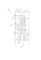
図3は、電子機器100の回路構成を示すブロック図である。この図に示すように、電子機器100は、ソーラーセル22と、二次電池24と、GPS受信回路30と、制御回路40と、ダイオード41と、充電制御用スイッチ42と、充電状態検出回路43と、電圧検出回路44と、時計部50とを備えている。なお、本発明における発電状態検出回路は、充電状態検出回路43と、電圧検出回路44とから構成される。
FIG. 3 is a block diagram illustrating a circuit configuration of the
制御回路40は、衛星信号受信装置を備える電子機器100を制御するためのCPUで構成されている。この制御回路40は、後述するように、GPS受信回路30を制御して受信処理を実行する。また、制御回路40は、充電状態検出回路43、電圧検出回路44の動作を制御する。
The
ダイオード41は、ソーラーセル22と二次電池24とを電気的に接続する経路に設けられ、ソーラーセル22から二次電池24への電流(順方向電流)を遮断せずに、二次電池24からソーラーセル22への電流(逆方向電流)を遮断する。なお、順方向電流が流れるのは、二次電池24の電圧よりもソーラーセル22の電圧が高い場合、すなわち充電時に限られる。また、ダイオード41に代えて電界効果トランジスター(FET)を採用してもよい。
The
充電制御用スイッチ42は、ソーラーセル22から二次電池24への電流の経路を接続及び切断するものであり、ソーラーセル22と二次電池24とを電気的に接続する経路に設けられたスイッチング素子421を備えている。スイッチング素子421がオフ状態からオン状態に遷移するとオン(接続)し、スイッチング素子421がオン状態からオフ状態へ遷移するとオフ(切断)する。
例えば、過充電により電池特性が劣化する状態にならないよう、二次電池24の電池電圧が所定値以上となる場合には、充電制御用スイッチ42をオフする
The
For example, the charging
スイッチング素子421は、pチャネル型のトランジスターであり、ゲート電圧Vg1がローレベルの場合にはオン状態となり、ハイレベルの場合にはオフ状態となる。ゲート電圧Vg1は、制御回路40に制御される。
The switching
充電状態検出回路43は、充電状態の検出タイミングを指定する2値の制御信号CTL1に基づいて作動し、ソーラーセル22から二次電池24への充電の状態(充電状態)を検出し、検出結果RS1を制御回路40へ出力する。充電状態は「充電中」または「非充電中」であり、その検出は電池電圧VCCと充電制御用スイッチ42がオンのときのソーラーセル22のPVINとに基づいて行われる。例えば、ダイオード41の降下電圧をVthとし、スイッチング素子421のオン抵抗を無視したとき、PVIN−Vth>VCCの場合には「充電中」と判定し、PVIN−Vth≦VCCの場合には「非充電中」と判定することができる。
The charging
本実施形態では、制御信号CTL1は、周期が1秒のパルス信号であり、充電状態検出回路43は、制御信号CTL1がハイレベルの期間において充電状態の検出を行う。つまり、充電状態検出回路43は、充電制御用スイッチ42を接続状態に維持したまま、充電状態の検出を1秒周期で繰り返し行う。
In the present embodiment, the control signal CTL1 is a pulse signal having a cycle of 1 second, and the charge
なお、充電状態の検出を間欠的に行うのは、充電状態検出回路43の消費電力量を低減するためである。この低減が不要であれば、充電状態が連続的に検出されるようにしてもよい。充電状態検出回路43は、例えば、コンパレーター、A/Dコンバーター等を用いて構成することができる。
The reason why the state of charge is detected intermittently is to reduce the amount of power consumed by the state of
電圧検出回路44は、電圧の検出タイミングを指定する2値の制御信号CTL2に基づいて作動し、この制御信号CTL2により充電制御用スイッチ42がオフとされた期間においてソーラーセル22の端子電圧PVIN、すなわちソーラーセル22の開放電圧を検出する。また、電圧検出回路44は、開放電圧の検出結果RS2を制御回路40へ出力する。
The
時計部50は、ムーブメント21を備え、二次電池24に蓄積された電力で駆動されて計時処理を行う。計時処理では、時刻を計時する一方、計時時刻に応じた時刻(表示時刻)を電子機器100の表面に表示させる。
The
[制御回路の動作]
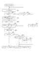
このような電子機器100における制御回路40の動作について、図4のフローチャートに基づき説明する。
制御回路40は、毎日12時0分0秒に制御を始める。先ず、制御回路40は、一定周期で充電状態検出回路43を作動する(SA1)。本実施形態では、図5に示すように、制御回路40は、1秒間隔の制御信号CTL1を出力し、充電状態検出回路43を作動している。制御信号CTL1が入力されると、充電状態検出回路43は、充電状態であるか否かを示す検出結果RS1を制御回路40に出力する。このため、制御回路40は、充電中であるか否かを判定する(SA2)。なお、充電制御用スイッチ42は、後述するように、電圧検出回路44が作動されるタイミングのみオフに切り替えられる。
[Operation of control circuit]
The operation of the
The
[非充電状態での制御]
電子機器100に当たる光が暗く、ソーラーセル22で発電が行われていない場合、充電状態検出回路43は「非充電中」の検出結果RS1を制御回路40に出力する。この場合、制御回路40は充電中ではない(SA2:No)と判定し、制御回路40からはローレベルの制御信号CTL2を出力する。
従って、SA2でNoと判定された場合、制御回路40は、電子機器100が屋外に配置されておらず、GPS信号の受信に適した場所に配置されていない可能性が高いと判断できる。
[Control in non-charged state]
When the light hitting the
Therefore, when it is determined No in SA2, the
[充電状態での制御]
一方、制御回路40は、SA2で充電状態である(SA2:Yes)と判定された場合、電圧検出回路44を作動する(SA3)。この際、前述の通り、充電制御用スイッチ42は、制御回路40によってオフ状態に切り替えられる。すなわち、制御回路40は、充電状態検出回路43で充電中であることを検出すると、1秒間隔の制御信号CTL2を出力し、電圧検出回路44を作動する。この際、充電制御用スイッチ42は、制御回路40からの制御信号CTL2によってオフ状態に制御されるので、ソーラーセル22及び電圧検出回路44は、二次電池24とは切り離される。このため、電圧検出回路44は、二次電池24の充電電圧の影響を受けることなく、ソーラーセル22に当たる光の照度に対応する開放電圧を検出できる。
なお、充電制御用スイッチ42がオフ状態では充電状態検出回路43によって充電状態を検出できない。このため、制御回路40は、充電状態検出回路43に対する制御信号CTL1の出力タイミングと、電圧検出回路44に対する制御信号CTL2の出力タイミングとが一致しないように、制御信号CTL1と制御信号CTL2の出力タイミングをずらしている。
[Control while charging]
On the other hand, the
When the
本実施形態では、電圧検出回路44で検出される開放電圧は、図6に示すように、ソーラーセル22における照度が高くなるほど高くなる。
また、電圧検出回路44として、ソーラーセル22の開放電圧の代わりにソーラーセル22の短絡電流を検出することで、ソーラーセル22に当たる照度を検出する構成を用いてもよい。すなわち、図7に示すように、ソーラーセル22における照度が高くなるほど高くなる短絡電流が検出される構成を適用してもよい。なお、短絡電流を検出する構成においても、開放電圧を検出する構成と同様に、充電制御用スイッチ42をオフにしてソーラーセル22と二次電池24とを電気的に切断することで、二次電池24の影響を受けないようにする必要がある。
このような開放電圧及び短絡電流は、ソーラーセル22における出力値と相関関係がある。そこで、本実施形態では、検出値として開放電圧や短絡電流を検出している。
In the present embodiment, the open circuit voltage detected by the
The
Such an open circuit voltage and a short circuit current have a correlation with the output value in the
制御回路40は、電圧検出回路44から出力される検出結果RS2により、開放電圧に対応する検出レベルを判定する(SA4)。本実施形態では、制御回路40は検出レベルを図8に示す関係に基づいて判定する。なお、図8における開放電圧と照度は、各検出レベルにおける下限値を表したものである。例えば、制御回路40は、開放電圧が5.6V以上5.8V未満の場合、検出レベルが「7」であり、5.9V以上6.2V未満の場合、検出レベルが「9」であると判定する。
The
図4に示すように、制御回路40は、SA4で得られた検出レベルが、1秒間隔での電圧検出に基づいて2回連続して、予め設定された閾値である閾レベル以上か否かを判定する(SA5)。ここで、閾レベルとソーラーセルでの開放電圧との関係は、図8に示す関係に基づいて、予め設定されている。つまり、ソーラーセル22に当たる光の照度が予め設定された照度閾値レベル以上である高照度状態であるか、照度閾値レベルよりも低い低照度状態であるかを判定するための閾値は、この図に基づいて設定されている。但し、閾レベルとソーラーセルでの開放電圧との関係は、図8に示す関係に限定されず、適宜設定することができる。また、後述するように、閾値はそのレベルが高くなったり低くなったりするが、本実施形態では、初期状態の閾レベルを「7」と規定している。蛍光灯下においてソーラーセル22に照射された場合の光の照度は通常500〜1000ルクスであるのに対し、直射日光がソーラーセル22に照射された場合の光の照度は通常10000ルクスを超える。そこで、ソーラーセル22に10000ルクスの光を当てた場合に対応する検出レベルである「7」を、初期状態の閾レベルとして規定している。
As shown in FIG. 4, the
SA5でNoと判定された場合(低照度状態である場合)、制御回路40は、電子機器100が屋外に配置されておらず、GPS信号の受信に適した場所に配置されていない可能性が高いと判断できる。
すなわち、電子機器100が屋外に配置され、かつ、昼間であれば、ソーラーセル22には、閾レベル以上の光が1秒以上継続して照射されるはずである。従って、1秒間隔で開放電圧を検出した場合、2回以上連続して閾レベル以上の開放電圧を検出した場合には、電子機器100が屋外に配置されている可能性が高いと判断できる。
一方、2回以上連続して閾レベル以上の開放電圧を検出できない場合には、例えば、電子機器100である腕時計を装着した人が、屋内を移動しているために開放電圧が1回も閾レベル以上とならない場合や、建物の窓から瞬間的に直射日光がソーラーセル22に当たったために2回以上連続して閾レベル以上とはならない場合等が想定される。このような条件では、GPS衛星信号を感度よく受信することが難しい。
従って、本実施形態では、SA5において、2回連続して検出レベルが閾レベル以上であるかを判断している。なお、このような判定としては、2回連続して検出レベルが閾レベル以上であるかを判断するものに限定されない。例えば、3回以上連続して検出レベルが閾レベル以上であることを条件としてもよいし、あるいは、検出レベルが閾レベル以上であることを1回検出したことを条件としてもよい。
When it is determined No in SA5 (when it is in a low illumination state), the
That is, if the
On the other hand, when the open voltage exceeding the threshold level cannot be detected continuously twice or more, for example, the person wearing the wristwatch, which is the
Therefore, in the present embodiment, in SA5, it is determined whether the detection level is equal to or higher than the threshold level twice in succession. Such determination is not limited to determining whether the detection level is equal to or higher than the threshold level twice consecutively. For example, it may be a condition that the detection level is equal to or higher than the threshold level continuously three times or more, or a condition that the detection level is equal to or higher than the threshold level is detected once.
SA2及びSA5のいずれかでNoと判定された場合には、現在の時刻が、制御回路40が制御を始めた日の翌日の11時59分59秒以前か否か判定する(SA6)。このようにして、制御回路40は、受信処理を行わずに、予め設定された発電状態検出時間が経過したか否か判定する。この場合、発電状態検出時間は24時間である。そして、SA6でNoと判定された場合は、SA1に戻り、一定周期で充電状態検出回路43を作動する。
If it is determined No in either SA2 or SA5, it is determined whether the current time is before 11:59:59 on the day after the day when the
一方で、SA6でYesと判定された場合(高照度状態である場合)は、閾レベルを1レベル低くなるように設定し直して(SA7)、処理を終了し、次に制御回路40での処理が開始される制御再開時間まで待機状態に移行する。ここで、制御再開時間は一秒後の12時0分0秒である。このように検出レベルが閾レベル未満の状態が発電状態検出時間(例えば24時間)以上の間継続した場合には、閾レベルを1レベル低くなるように設定し直すことで、検出レベルが閾レベル以上となりやすくなる。このように、GPS受信回路30を作動させる条件をより緩くしたため、GPS受信回路30を作動させる機会を設けることができる。
On the other hand, when it is determined Yes in SA6 (in the case of a high illuminance state), the threshold level is reset to be one level lower (SA7), the process is terminated, and then the
このように、SA6でYesと判定される場合としては様々な場合が想定されるが、ここでは、電子機器100のソーラーセル22の使用期間が長く、ソーラーセル22の劣化が進んだ場合について説明する。
図9は、各検出レベルにおけるソーラーセル22での開放電圧、及び、ソーラーセル22の使用日数に応じたソーラーセル22に当たる光の照度との関係を示す図である。また、図10は、ソーラーセル22に10000ルクスの光を当てた場合のソーラーセル22の使用日数と開放電圧との関係を示すグラフである。さらに、図11は、ソーラーセル22に10000ルクスの光を当てた場合のソーラーセル22の使用日数と短絡電流との関係を示すグラフである。
As described above, various cases are assumed as being determined as Yes in SA6. Here, the case where the use period of the
FIG. 9 is a diagram illustrating the relationship between the open-circuit voltage in the
図9〜図11に示すように、ソーラーセル22の使用日数が長くなれば、ソーラーセル22が劣化して電力変換効率が落ちる。このため、ソーラーセル22に同じ照度の光が当たっても、電圧検出回路44で使用日数が長くなると開放電圧がより低くなり、制御回路40で判定される検出レベルも低くなってしまう。このような場合には、閾レベルを固定してしまうと、制御回路40によって電子機器100が屋外に配置されていることを適切に判定できないため、問題が生じる。
本実施形態では、このようにソーラーセル22の劣化が進み、10000ルクスの光が当たっても、検出レベルが低くなって閾レベル以上とならず、受信処理が行われない場合に、閾レベルを徐々に低くしているので、GPS受信回路30を作動させる機会を設けることができる。
As shown in FIGS. 9 to 11, if the number of days of use of the
In this embodiment, when the
一方で、SA5でYesと判定された場合には、前述の通り、GPS衛星信号の受信に適した状態になっていると予測できるので、制御回路40は、GPS受信回路30を作動してGPS衛星の受信を開始する(SA8)。
なお、SA8で開始される受信処理は、所定の条件に該当した際に自動的に行われる自動受信処理である。この自動受信処理では、測時モードでの受信処理が行われる。すなわち、測位モードでは、位置を検出するために3個以上のGPS衛星から信号を受信しなければならず、受信処理時間も長くなる。このため、信号受信が終了するまで電子機器100を屋外に配置しておくことが好ましいが、自動受信処理では利用者が受信中であることに気がつかず、受信中であっても屋内に移動してしまうおそれもある。このため、測位モードでの受信は、利用者が意図して受信操作を行った場合のみ、つまり強制受信処理時のみ行うことが好ましい。
一方、測時モードでは、1つのGPS衛星からの信号受信でも時刻情報を取得でき、受信処理時間も短くできる。従って、利用者が意図しなくても、受信処理を実行することができ、自動受信処理に適している。
On the other hand, when it is determined Yes in SA5, it can be predicted that the GPS satellite signal is in a state suitable for reception as described above, and therefore the
The reception process started at SA8 is an automatic reception process that is automatically performed when a predetermined condition is met. In this automatic reception process, a reception process in the timekeeping mode is performed. That is, in the positioning mode, signals must be received from three or more GPS satellites in order to detect the position, and the reception processing time is also increased. For this reason, it is preferable to place the
On the other hand, in the time measurement mode, time information can be acquired even by receiving a signal from one GPS satellite, and the reception processing time can be shortened. Therefore, even if the user does not intend, the reception process can be executed, which is suitable for the automatic reception process.
また、受信処理中は、アンテナ基板27の上面に指針12があると受信感度に影響するため、アンテナ基板27の上面に指針12が重ならないようにモーターを制御することが好ましい。
Further, during the reception process, if the
制御回路40は、図4に示すように、SA8で開始される受信処理によりGPS衛星信号の受信に成功したか否かを判定する(SA9)。
なお、GPS受信回路30では、先ず、GPS衛星の検索を行い、GPS受信回路30でGPS衛星信号を検出する。そして、GPS衛星信号を検出した場合には、引き続きGPS衛星信号の受信を継続し、時刻情報を受信する。このように時刻情報を受信できた場合には、受信処理によりGPS衛星信号の受信に成功したと判定する。それ以外の場合、すなわち、GPS受信回路30でGPS衛星信号が検出されない場合や、時刻情報を受信できなかった場合には、受信処理によりGPS衛星信号の受信に失敗したと判定する。
受信処理によりGPS衛星信号の受信に成功した(SA9:Yes)と判定された場合には、処理を終了し、制御再開時間である翌日の12時0分0秒まで待機状態に移行する。
As shown in FIG. 4, the
The
If it is determined that the GPS satellite signal has been successfully received by the reception process (SA9: Yes), the process ends, and the process shifts to a standby state until 12:00:00 on the next day, which is the control resumption time.
一方で、受信処理によりGPS衛星信号の受信に失敗した(SA9:No)と判定された場合には、閾レベルを1レベル高くなるように設定し直して(SA10)、処理を終了し、制御再開時間である翌日の12時0分0秒まで待機状態に移行する。このようにすれば、翌日の12時0分0秒からSA1の処理を再開する場合に、閾レベルが1レベル高くなることで、検出レベルが閾レベル以上となりにくくなる。より具体的には、屋内に配置された電子機器100に照明の光が非常に強く照射され、検出レベルが閾レベル以上となっていたために受信処理が行われた場合には、受信に失敗するために閾レベルが1レベルずつ高くなる。そして、このように閾レベルが1レベルずつ高くなることで、いずれは照明の光では検出レベルが閾レベル以上とはならなくなり、屋外に移動して直射日光が照射した場合のみ閾レベル以上となる。このようにして、電子機器100を使用する人の生活環境に合わせて閾レベルの最適化を図ることができる。以上のように、GPS受信回路30でGPS衛星信号の受信に失敗した場合に、GPS受信回路30を作動させる条件をより厳しくすることにより、GPS衛星信号の受信に適した環境でGPS受信回路30を作動させることとなる。
On the other hand, if it is determined that the reception of the GPS satellite signal has failed (SA9: No) by the reception process, the threshold level is reset to be one level higher (SA10), the process is terminated, and the control is completed. It shifts to the standby state until 12:00:00 on the next day, which is the restart time. In this way, when the SA1 process is resumed from 12:00:00 on the next day, the detection level is less likely to be higher than the threshold level by increasing the threshold level by one level. More specifically, when the
このような第1実施形態によれば、以下の作用効果が得られる。
制御回路40は、GPS受信回路30でGPS衛星信号の受信に失敗した場合に、閾レベルを1レベル高くなるように設定し直している。このような場合、閾レベルが1レベル高くなることで、検出レベルが閾レベル以上となりにくくなる。このように、GPS受信回路30でGPS衛星信号の受信に失敗した場合に、GPS受信回路30を作動させる条件をより厳しくすることにより、GPS衛星信号の受信に適した環境でGPS受信回路30を作動させることとなる。そのため、ソーラーセル22を利用してGPS衛星信号の受信に適した環境か否かを精度よく判断でき、消費電力を抑制できる。
According to such 1st Embodiment, the following effects are obtained.
The
また、制御回路40は、検出レベルが閾レベル未満の状態が発電状態検出時間以上の間継続した場合には、閾レベルを1レベル低くなるように設定し直している。このような場合には、閾レベルが1レベル低くなることで、検出レベルが閾レベル以上となりやすくなる。このように、GPS受信回路30を作動させる条件をより緩くしたため、GPS受信回路30を作動させる機会を設けることができる。このようにすれば、ソーラーセル22を利用してGPS衛星信号の受信に適した環境か否かを精度よく判断でき、消費電力を抑制できる。
In addition, the
制御回路40での処理が終了した場合には、制御再開時間である翌日の12時0分0秒まで待機状態に移行するので、必要以上にGPS受信回路30が作動することを防止できる。そのため、消費電力を更に抑制できる。
When the processing in the
電圧検出回路44は、充電制御用スイッチ42を切断した状態でソーラーセル22の開放電圧を検出している。このため、電圧検出回路44は、二次電池24の影響を受けることなく、ソーラーセル22の開放電圧を高精度に検出できる。このため、ソーラーセル22の開放電圧つまりソーラーセル22における照度をより高精度に検出でき、ソーラーセル22を利用した屋内外判定を、二次電池24の電圧や充電状態で判定する場合に比べて高精度に行うことができる。
The
そして、電圧検出回路44で電子機器100が屋外に配置されていると検出された場合のみ受信が行われるため、衛星信号の受信に短時間で成功する確率を高めることができ、受信処理を効率的に行うことができる。従って、電子機器100が屋内に配置されて、衛星信号を受信できない環境で受信処理が行われることを未然に防止でき、無駄な電力消費を防止できる。
Since reception is performed only when the
また、制御回路40は、充電状態検出回路43で充電状態が検出されている場合のみ、電圧検出回路44を作動しているので、充電が行われていない状態つまり光がソーラーセル22に照射していない状態で電圧検出回路44が作動されることがなく、無駄な電力消費を防止できる。
Further, since the
充電状態検出回路43による充電状態の検出処理を1秒間隔で行い、電圧検出回路44による発電状態の検出処理は充電状態検出回路43によって充電中であると判定された場合のみ実行されるので、電圧検出回路44の作動時間つまりは充電制御用スイッチ42がオフされる時間を最小限に抑えることができる。このため、ソーラーセル22による充電効率の低下も抑えることができる。
The charge state detection process by the charge
[第2実施形態]
次に、本発明の第2実施形態を図面に基づいて説明する。
なお、本実施形態の電子機器の構造は、前記第1実施形態と同様であるから、その詳細な説明は省略または簡略化する。
[Second Embodiment]
Next, 2nd Embodiment of this invention is described based on drawing.
Note that the structure of the electronic device of the present embodiment is the same as that of the first embodiment, and thus detailed description thereof is omitted or simplified.
図12は、第2実施形態における制御回路での処理を示すフローチャートである。
本実施形態では、前記第1実施形態に対して、(i)制御回路40が、毎日12時0分0秒及び0時0分0秒に制御を始める点、(ii)受信処理によりGPS衛星信号の受信に失敗したと判定された場合に、更にGPS受信回路30でGPS衛星信号が検出されていたか否かを判定した上で、閾レベルを設定し直す点が異なるのみである。制御回路でのSB1〜SB9の処理については、前記第1実施形態におけるSA1〜SA9の処理と同様である。
FIG. 12 is a flowchart illustrating processing in the control circuit according to the second embodiment.
In this embodiment, compared to the first embodiment, (i) the
本実施形態では、制御回路40が、毎日12時0分0秒及び0時0分0秒に制御を始めるように設定されている。このように、本発明では制御回路40が受信制御を始める頻度は、特に限定されない。そこで、この頻度は、消費電力等を考慮して、適宜設定することができる。
また、制御回路40は、前記第1実施形態におけるSA1〜SA6の処理と同様の処理であるSB1〜SB6の処理を1秒間隔で繰り返すが、発電状態検出時間は12時間に設定されている。
さらに、制御回路40での処理を終了した場合には、制御再開時間である次の12時0分0秒または0時0分0秒からSB1の処理を再開する。
In the present embodiment, the
The
Further, when the processing in the
本実施形態では、受信処理によりGPS衛星信号の受信に失敗した(SB9:No)と判定された場合に、GPS受信回路30でGPS衛星信号が検出されていたか否かを判定する(SB10)。
そして、GPS受信回路30でGPS衛星信号が検出されていなかった(SB10:No)と判定された場合には、閾レベルを1レベル高くなるように設定し直して(SB11)、処理を終了し、制御再開時間である次の12時0分0秒または0時0分0秒まで待機状態に移行する。
一方、GPS受信回路30でGPS衛星信号が検出されていた(SB10:Yes)と判定された場合には、閾レベルはそのままにして、処理を終了し、制御再開時間である次の12時0分0秒または0時0分0秒まで待機状態に移行する。なお、GPS衛星信号の受信レベルが所定レベル以上であれば、GPS衛星信号が検出されたと判定する。また、GPS衛星信号を検出できる衛星が少なくとも1つあれば、GPS衛星信号が検出されたと判定しているが、GPS衛星信号が検出されたと判定するのに必要な衛星の数は特に限定されない。
In the present embodiment, when it is determined that the reception of the GPS satellite signal has failed (SB9: No) by the reception process, it is determined whether or not the GPS satellite signal has been detected by the GPS receiving circuit 30 (SB10).
If it is determined that the GPS satellite signal has not been detected by the GPS receiving circuit 30 (SB10: No), the threshold level is reset to be one level higher (SB11), and the process is terminated. Then, it shifts to the standby state until the next 12:00:00 or 0: 0: 0, which is the control resumption time.
On the other hand, if it is determined that the GPS satellite signal has been detected by the GPS receiving circuit 30 (SB10: Yes), the threshold level is left as it is, the processing is terminated, and the next control time is 12:00. It shifts to the standby state until
このような第2実施形態によれば、前記第1実施形態で得られる作用効果の他に、以下の作用効果が得られる。
制御再開時間が次の12時0分0秒または0時0分0秒であり、毎日2回であることにより、毎日1回の場合と比較して早く閾値の最適化を図ることができる。
受信処理によりGPS衛星信号の受信に失敗したとしても、GPS衛星信号を検出していた場合には、例えば、受信処理を開始した直後にビルの陰に入ってしまった等、他の要因により受信に失敗した可能性が高く、GPS衛星信号の受信に適した環境にあった可能性が高いといえる。そこで、制御回路40は、仮にGPS衛星信号の受信に失敗したとしても、GPS衛星信号が検出されていた場合には、閾レベルを変更する必要はないとみなしている。そして、GPS受信回路30でGPS衛星信号が検出されない場合のみ、閾レベルを1レベル高くなるように設定し直すこととしている。このようにすれば、衛星信号の受信に適した環境か否かをより精度よく判断できる。
According to the second embodiment as described above, the following functions and effects can be obtained in addition to the functions and effects obtained in the first embodiment.
Since the control resumption time is the next 12:00:00 or 0: 0: 0, and it is twice a day, the threshold can be optimized earlier than once a day.
Even if reception of the GPS satellite signal fails due to reception processing, if the GPS satellite signal is detected, it may be received due to other factors such as entering the shadow of the building immediately after starting reception processing. Therefore, it is highly possible that the environment was suitable for receiving GPS satellite signals. Therefore, even if reception of the GPS satellite signal fails, the
[第3実施形態]
次に、本発明の第3実施形態を図面に基づいて説明する。
なお、本実施形態の電子機器の構造は、前記第1実施形態と同様であるから、その詳細な説明は省略または簡略化する。
[Third Embodiment]
Next, 3rd Embodiment of this invention is described based on drawing.
Note that the structure of the electronic device of the present embodiment is the same as that of the first embodiment, and thus detailed description thereof is omitted or simplified.
図13は、第3実施形態における制御回路での処理を示すフローチャートである。
本実施形態では、前記第1実施形態に対して、(i)受信処理によりGPS衛星信号の受信に失敗したと判定された場合に、更にGPS受信回路30でGPS衛星信号が検出されていたか否かを判定した上で、閾レベルを設定し直す点、(ii)GPS衛星信号の受信処理を所定の時間間隔で実行するにあたり、GPS受信回路30がGPS衛星信号の受信に成功した場合の前記時間間隔を第一時間間隔とし、GPS受信回路30がGPS衛星信号の受信に失敗した場合の前記時間間隔を第二時間間隔とした場合に、前記第一時間間隔を、前記第二時間間隔よりも長くする点が異なるのみである。制御回路でのSC1〜SC9の処理については、前記第1実施形態におけるSA1〜SA9の処理と同様である。
FIG. 13 is a flowchart illustrating processing in the control circuit according to the third embodiment.
In the present embodiment, compared to the first embodiment, (i) whether or not the GPS satellite signal is further detected by the
本実施形態では、受信処理によりGPS衛星信号の受信に失敗した(SC9:No)と判定された場合に、更にGPS受信回路30でGPS衛星信号が検出されていたか否かを判定した上で(SC10)、閾レベルを設定し直すが、このような制御回路でのSC10及びSC11の処理については、前記第2実施形態におけるSB10及びSB11の処理と同様である。 In this embodiment, when it is determined that the reception of the GPS satellite signal has failed (SC9: No) by the reception process, it is further determined whether or not the GPS satellite signal has been detected by the GPS receiving circuit 30 ( SC10), the threshold level is reset, but the processing of SC10 and SC11 in such a control circuit is the same as the processing of SB10 and SB11 in the second embodiment.
本実施形態では、受信処理によりGPS衛星信号の受信に成功した(SC9:Yes)と判定された場合には、処理を終了し、制御再開時間である翌々日の12時0分0秒まで待機状態に移行する。これに対し、受信処理によりGPS衛星信号の受信に失敗した(SC9:No)と判定された場合、或いは、SC6でYesと判定された場合には、SC7、SC10またはSC11の処理の後に、処理を終了し、制御再開時間である翌日の12時0分0秒まで待機状態に移行する。このように、GPS衛星信号の受信処理を所定の時間間隔で実行するにあたり、GPS衛星信号の受信に成功した場合の第一時間間隔を、受信に失敗した場合の第二時間間隔よりも長くしている。
なお、衛星信号受信装置を電子機器100としてのクオーツ時計に組み込み、GPS衛星信号を受信して時刻情報を修正する場合、クオーツ時計の時刻精度により、GPS衛星信号を受信して時刻を修正した場合は、その後数日間は電子機器の時刻精度を十分に保つことができる。このため、暫く衛星信号を受信する必要は低くなる。一方、受信処理により衛星信号の受信に失敗した場合には、時間をあけずに衛星信号を受信する必要が高まる。
そこで、本実施形態では、GPS衛星信号の受信に成功した場合の第一時間間隔を、受信に失敗した場合の第二時間間隔よりも長くしている。このようにすれば、GPS衛星信号の受信に成功した場合は、次にGPS衛星信号を受信するまでの時間を長くでき、必要以上に受信回路が作動することを防止でき、消費電力を更に抑制できる。
In this embodiment, when it is determined that the reception of the GPS satellite signal is successful (SC9: Yes) by the reception process, the process ends, and the standby state is set until 12:00:00 on the next day, which is the control resumption time. Migrate to On the other hand, if it is determined that the reception of the GPS satellite signal has failed (SC9: No) by the reception process, or if it is determined Yes in SC6, the process is performed after the process of SC7, SC10, or SC11. Is finished, and the process shifts to a standby state until 12:00:00 on the next day, which is the control resumption time. As described above, when the GPS satellite signal reception process is executed at a predetermined time interval, the first time interval when the GPS satellite signal is successfully received is set longer than the second time interval when the reception is failed. ing.
When the satellite signal receiving device is incorporated in a quartz clock as the
Therefore, in the present embodiment, the first time interval when the GPS satellite signal is successfully received is longer than the second time interval when the reception is unsuccessful. In this way, if the GPS satellite signal is successfully received, the time until the next GPS satellite signal can be received can be lengthened, and the receiving circuit can be prevented from operating more than necessary, further reducing power consumption. it can.
このような第3実施形態によれば、前記第1実施形態及び前記第2実施形態で得られる作用効果の他に、以下の作用効果が得られる。
制御回路40での受信処理の実行間隔を、GPS衛星信号の受信に成功した場合の第一時間間隔を、受信に失敗した場合の第二時間間隔よりも長くすることで、GPS衛星信号の受信に成功した場合は、次にGPS衛星信号を受信するまでの時間を長くでき、必要以上に受信回路が作動することを防止でき、消費電力を更に抑制できる。
According to such 3rd Embodiment, in addition to the effect obtained by the said 1st Embodiment and the said 2nd Embodiment, the following effects are obtained.
The reception interval of the reception process in the
[第4実施形態]
次に、本発明の第4実施形態を図面に基づいて説明する。
なお、本実施形態の電子機器の構造は、前記第1実施形態と同様であるから、その詳細な説明は省略または簡略化する。
[Fourth Embodiment]
Next, 4th Embodiment of this invention is described based on drawing.
Note that the structure of the electronic device of the present embodiment is the same as that of the first embodiment, and thus detailed description thereof is omitted or simplified.
図14は、第4実施形態における制御回路での処理を示すフローチャートである。
本実施形態では、前記第1実施形態に対して、(i)検出値がソーラーセルの出力値が継続して所定値以上となっている時間である発電判定時間であり、閾値がこの発電判定時間である点が異なるのみである。つまり、前記第1実施形態と本実施形態とは、主として、SA5の処理に代えてSD5の処理をしている点で相違する。制御回路でのSD1〜SD4、SD6、SD8及びSD9の処理については、前記第1実施形態におけるSA1〜SA4、SA6、SA8及びSA9の処理と同様である。
FIG. 14 is a flowchart illustrating processing in the control circuit according to the fourth embodiment.
In the present embodiment, compared to the first embodiment, (i) the detected value is a power generation determination time that is a time during which the output value of the solar cell is continuously greater than or equal to a predetermined value, and the threshold value is the power generation determination. The only difference is the time. That is, the first embodiment is different from the present embodiment mainly in that SD5 processing is performed instead of SA5 processing. The processing of SD1 to SD4, SD6, SD8 and SD9 in the control circuit is the same as the processing of SA1 to SA4, SA6, SA8 and SA9 in the first embodiment.
本実施形態では、制御回路40は、1秒間隔での電圧検出に基づいて、判定回数(例えば10回)以上連続して検出レベルが閾レベル以上であったかを判定する(SD5)。ここで、判定回数は予め設定されている。なお、1秒間隔で開放電圧を検出した場合には、判定回数と発電判定時間との関係は図15に示す通りとなる。例えば、判定回数が「5」であれば発電判定時間は「5」秒であり、判定回数が「10」であれば発電判定時間は「10」秒である。このように電圧検出の間隔が一定である以上、判定回数と発電判定時間との間には相関関係がある。但し、判定回数と発電判定時間との関係は、図15に示す関係に限定されず、電圧検出の間隔に応じて変化する。例えば、2秒間隔で開放電圧を検出した場合には、判定回数が「5」であれば発電判定時間は「10」秒となる。また、後述するように、判定回数はその回数が多くなったり少なくなったりするが、本実施形態では、初期状態の判定回数を「10」(発電判定時間を「10」秒)と規定している。
In the present embodiment, the
SD5でNoと判定された場合、制御回路40は、電子機器100がGPS衛星信号の受信に適した環境に配置されていない可能性が高いと判断できる。
すなわち、電子機器100が屋外に配置され、かつ、昼間であれば、ソーラーセル22には、閾レベル以上の光が発電判定時間にわたり継続して照射されるはずである。従って、1秒間隔で開放電圧を検出した場合、判定回数以上連続して閾レベル以上の開放電圧を検出する。
一方、判定回数以上連続して閾レベル以上の開放電圧を検出できない場合には、例えば、車両等での移動中でビルの陰に入ってしまった場合等が想定される。このような条件では、GPS衛星信号の受信に失敗する可能性が高くなる。
When it is determined No in SD5, the
That is, if the
On the other hand, when the open circuit voltage exceeding the threshold level cannot be detected continuously for the number of times of determination, for example, a case where the vehicle enters the shadow of a building while moving in a vehicle or the like is assumed. Under such conditions, there is a high possibility that the reception of the GPS satellite signal will fail.
本実施形態では、SD6でYesと判定された場合は、判定回数を1回少なくなるように設定し直して(SD7)、処理を終了し、次に制御回路40での処理が開始される制御再開時間まで待機状態に移行する。ここで、制御再開時間は翌日の12時0分0秒である。このように判定回数以上検出レベルが閾レベル未満の状態が発電状態検出時間以上の間継続した場合には、判定回数を1回少なくなるように設定し直すことで、判定回数以上連続して検出レベルが閾レベル以上となりやすくなる。このように、GPS受信回路30を作動させる条件をより緩くしたため、GPS受信回路30を作動させる機会を設けることができる。
In this embodiment, when it is determined Yes in SD6, the number of determinations is reset so as to decrease by 1 (SD7), the process is terminated, and then the process in the
本実施形態では、受信処理によりGPS衛星信号の受信に失敗した(SD9:No)と判定された場合には、判定回数を1回多くなるように設定し直して(SD10)、処理を終了し、制御再開時間である翌日の12時0分0秒まで待機状態に移行する。このようにすれば、翌日の12時0分0秒からSD1の処理を再開する場合に、判定回数が1回多くなることで、判定回数以上継続して検出レベルが閾レベル以上となりにくくなる。このように、GPS受信回路30を作動させる条件をより厳しくしたため、GPS衛星信号の受信に適した環境でGPS受信回路30を作動させることとなる。
In this embodiment, when it is determined that the reception of the GPS satellite signal has failed (SD9: No) by the reception process, the determination number is reset so as to increase once (SD10), and the process ends. Then, it shifts to the standby state until 12:00:00 on the next day, which is the control resumption time. In this way, when the SD1 process is restarted from 12:00:00 on the next day, the number of determinations is increased by one, so that the detection level does not easily exceed the threshold level more than the number of determinations. As described above, since the conditions for operating the
このような第4実施形態によれば、前記第1実施形態で得られる作用効果の他に、以下の作用効果が得られる。
判定回数が1回多くなることで、判定回数以上継続して検出レベルが閾レベル以上となりにくくなる。このように、GPS受信回路30でGPS衛星信号の受信に失敗した場合に、GPS受信回路30を作動させる条件をより厳しくすることにより、GPS衛星信号の受信に適した環境でGPS受信回路30を作動させることとなる。そのため、ソーラーセル22を利用してGPS衛星信号の受信に適した環境か否かを精度よく判断でき、消費電力を抑制できる。
According to the fourth embodiment as described above, the following functions and effects can be obtained in addition to the functions and effects obtained in the first embodiment.
When the number of determinations is increased by one, the detection level does not easily exceed the threshold level continuously for the number of determinations. As described above, when the
[第5実施形態]
次に、本発明の第5実施形態を図面に基づいて説明する。
なお、本実施形態の電子機器の構造は、前記第1実施形態と同様であるから、その詳細な説明は省略または簡略化する。
[Fifth Embodiment]
Next, a fifth embodiment of the present invention will be described with reference to the drawings.
Note that the structure of the electronic device of the present embodiment is the same as that of the first embodiment, and thus detailed description thereof is omitted or simplified.
図16は、第5実施形態における制御回路での処理を示すフローチャートである。
本実施形態では、前記第4実施形態に対して、(i)制御回路40が、毎日12時0分0秒及び0時0分0秒に制御を始める点、(ii)受信処理によりGPS衛星信号の受信に失敗したと判定された場合に、更にGPS受信回路30でGPS衛星信号が検出されていたか否かを判定した上で、閾レベルを設定し直す点が異なるのみである。制御回路でのSE1〜SE9の処理については、前記第4実施形態におけるSD1〜SD9の処理と同様である。
また、制御回路でのSE10及びSE11の処理については、前記第2実施形態におけるSB10及びSB11の処理と同様である。
FIG. 16 is a flowchart illustrating processing in the control circuit according to the fifth embodiment.
In this embodiment, compared to the fourth embodiment, (i) the
Further, the processing of SE10 and SE11 in the control circuit is the same as the processing of SB10 and SB11 in the second embodiment.
このような第5実施形態によれば、前記第1実施形態、前記第2実施形態及び前記第4実施形態で得られる作用効果と同様の効果が得られる。 According to such 5th Embodiment, the effect similar to the effect obtained by the said 1st Embodiment, the said 2nd Embodiment, and the said 4th Embodiment is acquired.
[第6実施形態]
次に、本発明の第6実施形態を図面に基づいて説明する。
なお、本実施形態の電子機器の構造は、前記第1実施形態と同様であるから、その詳細な説明は省略または簡略化する。
[Sixth Embodiment]
Next, a sixth embodiment of the present invention will be described with reference to the drawings.
Note that the structure of the electronic device of the present embodiment is the same as that of the first embodiment, and thus detailed description thereof is omitted or simplified.
図17は、第6実施形態における制御回路での処理を示すフローチャートである。
本実施形態では、前記第4実施形態に対して、(i)受信処理によりGPS衛星信号の受信に失敗したと判定された場合に、更にGPS受信回路30でGPS衛星信号が検出されていたか否かを判定した上で、閾レベルを設定し直す点、(ii)GPS衛星信号の受信処理を所定の時間間隔で実行するにあたり、GPS受信回路30がGPS衛星信号の受信に成功した場合の前記時間間隔を第一時間間隔とし、GPS受信回路30がGPS衛星信号の受信に失敗した場合の前記時間間隔を第二時間間隔とした場合に、前記第一時間間隔を、前記第二時間間隔よりも長くする点が異なるのみである。制御回路でのSF1〜SF8の処理については、前記第4実施形態におけるSD1〜SD8の処理と同様である。
また、制御回路でのSF9〜SF11の処理については、前記第3実施形態におけるSC9〜SC11の処理と同様である。
FIG. 17 is a flowchart showing the processing in the control circuit in the sixth embodiment.
In the present embodiment, compared to the fourth embodiment, (i) whether or not the GPS satellite signal is further detected by the
Further, the processing of SF9 to SF11 in the control circuit is the same as the processing of SC9 to SC11 in the third embodiment.
このような第6実施形態によれば、前記第1実施形態、前記第3実施形態及び前記第4実施形態で得られる作用効果と同様の効果が得られる。 According to such 6th Embodiment, the effect similar to the effect obtained by the said 1st Embodiment, the said 3rd Embodiment, and the said 4th Embodiment is acquired.
[他の実施形態]
なお、本発明は前記実施形態の構成に限定されず、本発明の要旨の範囲内で種々の変形実施が可能である。
例えば、前記実施形態では、制御回路40は、所定の条件を満たす場合には、閾値を変更しているが、制御回路40は、閾値を高くする場合に限って設定し直すことができるようにしてもよい。このようにすれば、衛星信号の受信に失敗した場合と同様の環境で受信処理を行う可能性が低くなり、少なくとも無駄に受信回路が作動することを防止できる。
前記実施形態では、制御回路40により閾値を制御しているが、閾値をボタン操作等により手動で変更できるようにしてもよい。
前記実施形態では、充電状態の検出を1秒間隔で行っていたが、この間隔に限定されず、例えば、0.5秒間隔、10秒間隔や1分間隔に設定してもよい。
前記実施形態では、自動受信処理時には測時モードで受信し、測位モードでの受信は強制受信処理時のみに行う形態としたが、当然、測位モードでの受信を自動受信処理で行ってもよい。例えば、自動受信処理時の受信モードを利用者が予め選択できるようにしておき、測位モードが選択された場合には自動受信処理時に測位モードで受信し、測時モードが選択された場合には自動受信処理時に測時モードで受信すればよい。
[Other Embodiments]
In addition, this invention is not limited to the structure of the said embodiment, A various deformation | transformation implementation is possible within the range of the summary of this invention.
For example, in the above-described embodiment, the
In the above-described embodiment, the threshold value is controlled by the
In the embodiment, the state of charge is detected at intervals of 1 second, but is not limited to this interval, and may be set at intervals of 0.5 seconds, intervals of 10 seconds, or intervals of 1 minute, for example.
In the above-described embodiment, the reception is performed in the timekeeping mode during the automatic reception processing, and the reception in the positioning mode is performed only during the forced reception processing. However, naturally, the reception in the positioning mode may be performed by the automatic reception processing. . For example, if the user can select the reception mode at the time of automatic reception processing in advance, if the positioning mode is selected, reception is performed in the positioning mode at the time of automatic reception processing, and if the timekeeping mode is selected What is necessary is just to receive in timekeeping mode at the time of automatic reception processing.
前記実施形態では、所定の条件を満たす場合には、制御回路40は、閾値を低くなるように設定し直している。このような場合、制御回路40は、複数回連続して、前記閾値を低くなるように設定し直した場合には、GPS受信回路30、充電制御用スイッチ42及び電圧検出回路44をスリープ状態に移行させ、スリープ状態から通常状態に移行する状態を検出し、GPS受信回路30、充電制御用スイッチ42及び電圧検出回路44がスリープ状態から通常状態に移行する場合には、前記閾値を初期値に設定し直すことが好ましい。スリープ状態から通常状態に移行する状態としては、例えばボタン操作等によりスリープ状態を解除する操作がされた場合や、ソーラーセル22に所定照度以上の光が当たったことが検出された場合が挙げられる。
In the embodiment, when a predetermined condition is satisfied, the
例えば、衛星信号受信装置を備える電子機器100を光が当たらない場所で保管する場合には、制御回路40は、複数回連続して、閾値を低くなるように設定し直すこととなる。このような場合、GPS受信回路30及び発電状態検出回路を作動させても無駄であるため、スリープ状態、つまり作動停止状態に移行することで、消費電力を低減できる。
また、このスリープ状態は、使用者がボタン操作することなどで解除できる。この場合、閾値がスリープ状態に移行する前のままであると低くなりすぎているために、無駄にGPS受信回路30が作動することとなる。そこで、このように、スリープ状態から通常状態に移行する場合には、前記閾値を初期値に設定し直すことで、閾値が低くなりすぎていることにより必要以上に受信回路が作動することを抑制できる。このようにして、消費電力を更に抑制できる。
For example, when the
The sleep state can be canceled by a user operating a button. In this case, since the threshold value is too low if the threshold value is not changed to the sleep state, the
前記実施形態では、制御回路40での処理が終了した場合には、制御再開時間まで待機状態に移行したが、待機状態に移行しないで制御回路40での処理を再開してもよい。このような場合、制御回路40は、GPS受信回路30の作動が終了した時点からの経過時間が、GPS受信回路30を作動させる間隔として設定される受信間隔設定時間以上であり、かつ、発電状態検出回路で検出された検出値が閾値以上となる場合のみ、GPS受信回路30を作動させることが好ましい。
In the embodiment, when the process in the
このように、GPS受信回路30の作動が終了した時点からの経過時間が、受信間隔設定時間以上でない場合には、GPS受信回路30が作動しないようにすることで、必要以上に受信回路が作動することを防止できる。このようにして、消費電力を更に抑制できる。
As described above, when the elapsed time from the time when the operation of the
前記実施形態では、制御回路40は、GPS受信回路30で衛星信号の受信に1回失敗した場合に、閾値を高くなるように設定し直しているが、制御回路40は、GPS受信回路30で衛星信号の受信に複数回連続して失敗した場合のみ、閾値を高くなるように設定し直すこととしてもよい。
In the above-described embodiment, the
このようにすれば、GPS受信回路30で衛星信号の受信に複数回連続して失敗した場合には、GPS受信回路30が衛星信号を受信できない環境にあると判定し、閾値を高くなるように設定し直しているため、例えば車両等での移動中にビルの陰に入ってしまった場合等のように、他の要因により必要以上に閾値が高くなることを抑制できる。このようにして、衛星信号の受信に適した環境か否かをより精度よく判断できる。
In this way, when the
前記第2実施形態、前記第3実施形態、前記第5実施形態及び前記第6実施形態では、GPS衛星信号を検出できる衛星が少なくとも1つあれば、GPS衛星信号が検出されたと判定しているが、GPS衛星信号が検出されたと判定するのに必要な衛星の数は特に限定されない。例えば、GPS衛星信号が検出されたと判定するのに必要な衛星の数を、測時モードの場合には1とし、測位モードの場合には3としてもよい。
測時モードの場合にはGPS衛星信号を検出できる衛星が少なくとも1つあれば、GPS衛星信号から時間情報を受信することができるのに対し、測位モードの場合にはGPS衛星信号を検出できる衛星が3つ以上なければ、GPS衛星信号からの位置情報に基づき電子機器の位置を特定することができない。そこで、上記のようにすることで、GPS衛星信号の受信に適した環境か否かをより精度よく判断できる。
In the second embodiment, the third embodiment, the fifth embodiment, and the sixth embodiment, if there is at least one satellite that can detect a GPS satellite signal, it is determined that the GPS satellite signal has been detected. However, the number of satellites required to determine that a GPS satellite signal has been detected is not particularly limited. For example, the number of satellites necessary to determine that a GPS satellite signal has been detected may be 1 in the timekeeping mode and 3 in the positioning mode.
In the time measurement mode, if there is at least one satellite that can detect a GPS satellite signal, time information can be received from the GPS satellite signal, whereas in the positioning mode, a satellite that can detect a GPS satellite signal. If there are no more than three, the position of the electronic device cannot be specified based on the position information from the GPS satellite signal. Thus, by doing as described above, it is possible to more accurately determine whether the environment is suitable for receiving GPS satellite signals.
前記実施形態では、制御回路40は、所定の条件を満たす場合には、閾値を変更しているが、この所定の条件は前述の条件に限定されない。
例えば、衛星信号の受信に連続して成功した場合に、閾値を高くなるように設定し直してもよい。衛星信号の受信に連続して成功するということは、電子機器100が衛星信号をかなり受信しやすい環境で使用されている可能性が高いと判断できる。このような場合には、閾値を高くして、受信回数を制限することで、電池寿命を優先するようにしてもよい。
測時モードから測位モードへと変更した場合に、閾値を高くなるように設定し直したり、測位モードから測時モードへと変更した場合に、閾値を低くなるように設定し直してもよい。測時モードの場合と比較して測位モードの場合には、GPS衛星信号をより受信しやすい環境であることが求められる。そこで、上記のようにすることで、GPS衛星信号の受信に適した環境か否かをより精度よく判断できる。
また、上記と同様の観点から、測時モードの場合と測位モードの場合とで、それぞれ閾値を区別して、それぞれ管理してもよい。
In the embodiment, the
For example, the threshold value may be reset so as to increase when satellite signal reception succeeds. Successful reception of satellite signals can be determined that there is a high possibility that the
When the time mode is changed to the positioning mode, the threshold value may be reset to be higher, or when the position mode is changed to the time mode, the threshold value may be reset to be lower. Compared to the time measurement mode, the positioning mode is required to provide an environment in which GPS satellite signals can be received more easily. Thus, by doing as described above, it is possible to more accurately determine whether the environment is suitable for receiving GPS satellite signals.
Further, from the same viewpoint as described above, threshold values may be distinguished and managed in the timekeeping mode and the positioning mode, respectively.
前記実施形態では、発電状態検出回路でソーラーセル22に当たる光の照度が高くなるほど高い値となる検出値を検出しているが、前記検出値はソーラーセル22に当たる光の照度が高くなるほど高い値となるものに限定されない。すなわち、前記検出値はソーラーセル22に当たる光の照度が高くなるほど低い値となるものであってもよい。なお、検出値がソーラーセル22に当たる光の照度が高くなるほど低い値となる場合としては、例えば、ソーラーセル22に当たる光の照度が高くなるほど、開放電圧が低くなるようなデバイスを用いる場合が挙げられる。
In the embodiment, the power generation state detection circuit detects a detection value that increases as the illuminance of light hitting the
本発明の衛星信号受信装置を備える電子機器100は、腕時計(電子時計)に限定されず、例えば、携帯電話、登山等に用いられる携帯型のGPS受信機等、二次電池で駆動されて位置情報衛星から送信される衛星信号を受信する装置に広く利用できる。
さらに、本発明では、ソーラーセル22、二次電池24、充電制御用スイッチ42、電圧検出回路44を備えることで、ソーラーセル22に照射された光の照度を高精度に検出することができる。これらの構成による照度の検出機構は、衛星信号受信装置のみに利用されるものではなく、他の機器にも適用できる。特に、照度の検出によって、何らかの装置を起動する機器に適している。例えば、照度に応じて、照明をオン・オフしたり、照明の光量を変化させる機器や、照度に応じて受信を開始する長波の電波修正時計等に応用できる。
The
Furthermore, in the present invention, the
100…電子機器、22…ソーラーセル、30…GPS受信回路、40…制御回路、43…充電状態検出回路、44…電圧検出回路。
DESCRIPTION OF
Claims (19)
光エネルギーを電気エネルギーに変換するソーラーセルと、
前記ソーラーセルの発電状態を検出する発電状態検出回路と、
前記受信回路と前記発電状態検出回路を制御する制御回路とを備え、
前記発電状態検出回路で検出された検出値は、前記ソーラーセルの出力値であり、
前記制御回路は、
前記ソーラーセルに当たる光の照度が予め設定された照度閾値レベル以上である高照度状態であるか、前記照度閾値レベルよりも低い低照度状態であるかを判定するための閾値を設定し、前記発電状態検出回路で検出される検出値と前記閾値とを比較して前記高照度状態であると判定された場合に、前記受信回路を作動し、
前記受信回路で位置情報衛星の検索を行い、前記受信回路で前記衛星信号が検出されずに、前記衛星信号の受信に失敗した場合には、前記照度閾値レベルが高くなるように前記閾値を設定し直す
ことを特徴とする衛星信号受信装置。 In a satellite signal receiving apparatus having a receiving circuit for receiving satellite signals,
A solar cell that converts light energy into electrical energy;
A power generation state detection circuit for detecting a power generation state of the solar cell;
A control circuit for controlling the reception circuit and the power generation state detection circuit;
The detection value detected by the power generation state detection circuit is an output value of the solar cell,
The control circuit includes:
A threshold for determining whether the illuminance of light hitting the solar cell is a high illuminance state that is equal to or higher than a preset illuminance threshold level or a low illuminance state lower than the illuminance threshold level is set, and the power generation When the detection value detected by the state detection circuit is compared with the threshold value and it is determined that the high illuminance state is present, the reception circuit is activated,
The receiving circuit searches for a location information satellite, and if the satellite signal fails to be detected without being detected by the receiving circuit, the illuminance threshold level is set to be high. A satellite signal receiving device characterized by re-working .
光エネルギーを電気エネルギーに変換するソーラーセルと、
前記ソーラーセルの発電状態を検出する発電状態検出回路と、
前記受信回路と前記発電状態検出回路を制御する制御回路とを備え、
前記発電状態検出回路で検出された検出値は、前記ソーラーセルの出力値であり、
前記制御回路は、
前記ソーラーセルに当たる光の照度が予め設定された照度閾値レベル以上である高照度状態であるか、前記照度閾値レベルよりも低い低照度状態であるかを判定するための閾値を設定し、前記発電状態検出回路で検出される検出値と前記閾値とを比較して前記高照度状態であると判定された場合に、前記受信回路を作動し、
前記受信回路で前記衛星信号の受信に失敗した場合には、前記照度閾値レベルが高くなるように前記閾値を変更し、
前記発電状態検出回路で検出された検出値に基づいて検出された前記低照度状態が、予め設定された発電状態検出時間以上の間継続した場合には、前記照度閾値レベルが低くなるように前記閾値を設定し直す
ことを特徴とする衛星信号受信装置。 In a satellite signal receiving apparatus having a receiving circuit for receiving satellite signals,
A solar cell that converts light energy into electrical energy;
A power generation state detection circuit for detecting a power generation state of the solar cell;
A control circuit for controlling the reception circuit and the power generation state detection circuit;
The detection value detected by the power generation state detection circuit is an output value of the solar cell,
The control circuit includes:
A threshold for determining whether the illuminance of light hitting the solar cell is a high illuminance state that is equal to or higher than a preset illuminance threshold level or a low illuminance state lower than the illuminance threshold level is set, and the power generation When the detection value detected by the state detection circuit is compared with the threshold value and it is determined that the high illuminance state is present, the reception circuit is activated,
When the reception circuit fails to receive the satellite signal, the threshold value is changed so that the illuminance threshold level becomes high,
When the low illuminance state detected based on the detection value detected by the power generation state detection circuit continues for a preset power generation state detection time or longer, the illuminance threshold level is reduced. A satellite signal receiving apparatus characterized by resetting a threshold value .
光エネルギーを電気エネルギーに変換するソーラーセルと、
前記ソーラーセルの発電状態を検出する発電状態検出回路と、
前記受信回路と前記発電状態検出回路を制御する制御回路とを備え、
前記発電状態検出回路で検出された検出値は、前記ソーラーセルの出力値と予め設定された照度閾値レベルに対応して設定された所定値とを比較して、前記ソーラーセルに当たる光の照度が前記照度閾値レベル以上である高照度状態であるか、前記照度閾値レベルよりも低い低照度状態であるかを判定した場合に、前記ソーラーセルの出力値が継続して前記高照度状態となっている時間である発電判定時間であり、
前記制御回路は、
前記発電判定時間が予め設定された発電判定時間の閾値以上である場合に、前記受信回路を作動し、
前記受信回路で前記衛星信号の受信に失敗した場合には、前記発電判定時間の閾値を長くなるように設定し直す
ことを特徴とする衛星信号受信装置。 In a satellite signal receiving apparatus having a receiving circuit for receiving satellite signals,
A solar cell that converts light energy into electrical energy;
A power generation state detection circuit for detecting a power generation state of the solar cell;
A control circuit for controlling the reception circuit and the power generation state detection circuit;
The detection value detected by the power generation state detection circuit compares the output value of the solar cell with a predetermined value set corresponding to a preset illuminance threshold level, and the illuminance of light hitting the solar cell is When it is determined whether the high illuminance state is equal to or higher than the illuminance threshold level or the low illuminance state is lower than the illuminance threshold level, the output value of the solar cell continuously becomes the high illuminance state. Power generation determination time,
The control circuit includes:
When the power generation determination time is equal to or greater than a preset power generation determination time threshold, the receiving circuit is activated,
A satellite signal receiving device, wherein when the reception circuit fails to receive the satellite signal, the threshold value of the power generation determination time is reset to be longer .
前記制御回路は、
前記受信回路で位置情報衛星の検索を行い、前記受信回路で前記衛星信号が検出されずに、前記衛星信号の受信に失敗した場合には、前記発電判定時間の閾値を長くなるように設定し直し、
前記受信回路で前記衛星信号が検出されていたが、前記衛星信号の受信に失敗した場合には、前記発電判定時間の閾値をそのまま維持する
ことを特徴とする衛星信号受信装置。 The satellite signal receiving device according to claim 3 ,
The control circuit includes:
To search for positioning information satellites by means of the reception circuit, the no satellite signal is detected by the receiving circuit, when failing to receive the satellite signal, set longer a threshold before Symbol generation determination time Rework,
The satellite signal receiving apparatus, wherein the threshold value of the power generation determination time is maintained as it is when the satellite signal is detected by the receiving circuit but reception of the satellite signal fails.
前記制御回路は、
前記発電判定時間が前記発電判定時間の閾値以上と判定されない状態が、予め設定された発電状態検出時間以上の間継続した場合には、前記発電判定時間の閾値を短くなるように設定し直す
ことを特徴とする衛星信号受信装置。 In the satellite signal receiver according to claim 3 or 4 ,
The control circuit includes:
The state in which the power generation determination time is not determined equal to or greater than the threshold value of the power determination time, if continued for more than a preset power generation state detection time, reset before SL so as to be shorter the threshold power determination time A satellite signal receiving device.
前記制御回路は、
複数回連続して、前記照度閾値レベルが低くなるように前記閾値を設定し直すか、または前記発電判定時間の閾値を短くなるように設定し直した場合には、前記受信回路及び前記発電状態検出回路をスリープ状態に移行させ、
前記スリープ状態から通常状態に移行する状態を検出し、前記受信回路及び前記発電状態検出回路が前記スリープ状態から前記通常状態に移行する場合には、前記閾値または前記発電判定時間の閾値を初期値に設定し直す
ことを特徴とする衛星信号受信装置。 In the satellite signal receiving device according to any one of claims 1 to 5 ,
The control circuit includes:
When the threshold value is reset so that the illuminance threshold level is lowered a plurality of times continuously, or when the threshold value of the power generation determination time is reset to be shorter, the receiving circuit and the power generation state Move the detection circuit to sleep state,
When the state of transition from the sleep state to the normal state is detected, and the reception circuit and the power generation state detection circuit transition from the sleep state to the normal state, the threshold value or the threshold value of the power generation determination time is set to the initial value. A satellite signal receiver characterized in that it is set again.
前記制御回路は、 The control circuit includes:
前記受信回路で位置情報衛星の検索を行い、前記受信回路で前記衛星信号が検出されずに、前記衛星信号の受信に失敗した場合には、前記照度閾値レベルが高くなるように前記閾値を設定し直し、 The receiving circuit searches for a location information satellite, and if the satellite signal fails to be detected without being detected by the receiving circuit, the illuminance threshold level is set to be high. Rework,
前記受信回路で前記衛星信号が検出されていたが、前記衛星信号の受信に失敗した場合には、前記閾値をそのまま維持する If the satellite signal has been detected by the receiving circuit, but the satellite signal has failed to be received, the threshold value is maintained as it is.
ことを特徴とする衛星信号受信装置。 A satellite signal receiving device.
前記制御回路は、
前記衛星信号の受信処理を所定の時間間隔で実行するとともに、
前記受信回路が前記衛星信号の受信に成功した場合の前記時間間隔を第一時間間隔とし、
前記受信回路が前記衛星信号の受信に失敗した場合の前記時間間隔を第二時間間隔とした場合に、
前記第一時間間隔を、前記第二時間間隔よりも長くする
ことを特徴とする衛星信号受信装置。 In the satellite signal receiver according to any one of claims 1 to 7 ,
The control circuit includes:
The satellite signal reception process is executed at predetermined time intervals, and
The time interval when the reception circuit has successfully received the satellite signal as the first time interval,
When the time interval when the reception circuit fails to receive the satellite signal as the second time interval,
The satellite signal receiver characterized in that the first time interval is longer than the second time interval.
前記制御回路は、
前記受信回路で前記衛星信号の受信に複数回連続して失敗した場合に、前記閾値または前記発電判定時間の閾値を変更する
ことを特徴とする衛星信号受信装置。 In the satellite signal receiving device according to any one of claims 1 to 8 ,
The control circuit includes:
The satellite signal receiving apparatus, wherein the threshold value or the threshold value of the power generation determination time is changed when the reception circuit fails to receive the satellite signal continuously a plurality of times.
光エネルギーを電気エネルギーに変換するソーラーセルと、
前記ソーラーセルの発電状態を検出する発電状態検出回路と、
前記受信回路と前記発電状態検出回路を制御する制御回路とを備え、
前記発電状態検出回路で検出された検出値は、前記ソーラーセルの出力値であり且つ前記ソーラーセルに当たる光の照度が高いほど大きくなる値であり、
前記制御回路は、
前記発電状態検出回路で検出される検出値と予め設定した閾値とを比較して前記検出値が前記閾値以上であると判定された場合に、前記受信回路を作動し、
前記受信回路で位置情報衛星の検索を行い、前記受信回路で前記衛星信号が検出されずに、前記衛星信号の受信に失敗した場合には、前記閾値が大きくなるように前記閾値を設定し直す
ことを特徴とする衛星信号受信装置。 In a satellite signal receiving apparatus having a receiving circuit for receiving satellite signals,
A solar cell that converts light energy into electrical energy;
A power generation state detection circuit for detecting a power generation state of the solar cell;
A control circuit for controlling the reception circuit and the power generation state detection circuit;
The detection value detected by the power generation state detection circuit is an output value of the solar cell and a value that increases as the illuminance of light hitting the solar cell increases.
The control circuit includes:
When the detection value detected by the power generation state detection circuit is compared with a preset threshold value and the detection value is determined to be greater than or equal to the threshold value, the reception circuit is activated.
The receiving circuit searches for a location information satellite, and if the satellite signal is not detected by the receiving circuit and fails to receive the satellite signal, the threshold value is reset so that the threshold value increases. A satellite signal receiving device.
光エネルギーを電気エネルギーに変換するソーラーセルと、 A solar cell that converts light energy into electrical energy;
前記ソーラーセルの発電状態を検出する発電状態検出回路と、 A power generation state detection circuit for detecting a power generation state of the solar cell;
前記受信回路と前記発電状態検出回路を制御する制御回路とを備え、 A control circuit for controlling the reception circuit and the power generation state detection circuit;
前記発電状態検出回路で検出された検出値は、前記ソーラーセルの出力値であり且つ前記ソーラーセルに当たる光の照度が高いほど小さくなる値であり、 The detection value detected by the power generation state detection circuit is an output value of the solar cell and a value that decreases as the illuminance of light hitting the solar cell increases.
前記制御回路は、 The control circuit includes:
前記発電状態検出回路で検出される検出値と予め設定した閾値とを比較して前記検出値が前記閾値以下と判定された場合に、前記受信回路を作動し、 When the detection value detected by the power generation state detection circuit is compared with a preset threshold value and the detection value is determined to be equal to or less than the threshold value, the reception circuit is operated.
前記受信回路で位置情報衛星の検索を行い、前記受信回路で前記衛星信号が検出されずに、前記衛星信号の受信に失敗した場合には、前記閾値が小さくなるように前記閾値を設定し直す The receiving circuit searches for a location information satellite, and if the satellite signal is not detected by the receiving circuit and fails to receive the satellite signal, the threshold is reset so that the threshold is reduced.
ことを特徴とする衛星信号受信装置。 A satellite signal receiving device.
光エネルギーを電気エネルギーに変換するソーラーセルと、 A solar cell that converts light energy into electrical energy;
前記ソーラーセルの発電状態を検出する発電状態検出回路と、 A power generation state detection circuit for detecting a power generation state of the solar cell;
前記受信回路と前記発電状態検出回路を制御する制御回路とを備え、 A control circuit for controlling the reception circuit and the power generation state detection circuit;
前記発電状態検出回路で検出された検出値は、前記ソーラーセルの出力値であり且つ前記ソーラーセルに当たる光の照度が高いほど大きくなる値であり、 The detection value detected by the power generation state detection circuit is an output value of the solar cell and a value that increases as the illuminance of light hitting the solar cell increases.
前記制御回路は、 The control circuit includes:
前記発電状態検出回路で検出される検出値と予め設定した閾値とを比較して前記検出値が前記閾値以上であると判定された場合に、前記受信回路を作動し、 When the detection value detected by the power generation state detection circuit is compared with a preset threshold value and the detection value is determined to be greater than or equal to the threshold value, the reception circuit is activated.
前記受信回路で前記衛星信号の受信に失敗した場合には、前記閾値が大きくなるように前記閾値を変更し、 When the reception circuit fails to receive the satellite signal, the threshold is changed so that the threshold is increased,
前記発電状態検出回路で検出された検出値が前記閾値未満の状態が、予め設定された発電状態検出時間以上の間継続した場合には、前記閾値が小さくなるように前記閾値を設定し直す When the state in which the detection value detected by the power generation state detection circuit is less than the threshold value continues for a preset power generation state detection time or longer, the threshold value is reset so that the threshold value decreases.
ことを特徴とする衛星信号受信装置。 A satellite signal receiving device.
光エネルギーを電気エネルギーに変換するソーラーセルと、 A solar cell that converts light energy into electrical energy;
前記ソーラーセルの発電状態を検出する発電状態検出回路と、 A power generation state detection circuit for detecting a power generation state of the solar cell;
前記受信回路と前記発電状態検出回路を制御する制御回路とを備え、 A control circuit for controlling the reception circuit and the power generation state detection circuit;
前記発電状態検出回路で検出された検出値は、前記ソーラーセルの出力値であり且つ前記ソーラーセルに当たる光の照度が高いほど小さくなる値であり、 The detection value detected by the power generation state detection circuit is an output value of the solar cell and a value that decreases as the illuminance of light hitting the solar cell increases.
前記制御回路は、 The control circuit includes:
前記発電状態検出回路で検出される検出値と予め設定した閾値とを比較して前記検出値が前記閾値以下であると判定された場合に、前記受信回路を作動し、 When the detection value detected by the power generation state detection circuit is compared with a preset threshold value and the detection value is determined to be less than or equal to the threshold value, the reception circuit is activated,
前記受信回路で前記衛星信号の受信に失敗した場合には、前記閾値が小さくなるように前記閾値を変更し、 When the reception circuit fails to receive the satellite signal, the threshold value is changed so that the threshold value is reduced,
前記発電状態検出回路で検出された検出値が前記閾値より大きい状態が、予め設定された発電状態検出時間以上の間継続した場合には、前記閾値が大きくなるように前記閾値を設定し直す When the state in which the detection value detected by the power generation state detection circuit is larger than the threshold value continues for a preset power generation state detection time or longer, the threshold value is reset so that the threshold value increases.
ことを特徴とする衛星信号受信装置。 A satellite signal receiving device.
光エネルギーを電気エネルギーに変換するソーラーセルと、 A solar cell that converts light energy into electrical energy;
前記ソーラーセルの発電状態を検出する発電状態検出回路と、 A power generation state detection circuit for detecting a power generation state of the solar cell;
前記受信回路と前記発電状態検出回路を制御する制御回路とを備え、 A control circuit for controlling the reception circuit and the power generation state detection circuit;
前記ソーラーセルの出力値は、前記ソーラーセルに当たる光の照度が高いほど大きくなる値であり、 The output value of the solar cell is a value that increases as the illuminance of light hitting the solar cell increases.
前記発電状態検出回路で検出された検出値は、前記ソーラーセルの出力値と予め設定された所定値とを比較して、前記ソーラーセルの出力値が継続して前記所定値以上となっている時間である発電判定時間であり、 The detection value detected by the power generation state detection circuit compares the output value of the solar cell with a predetermined value set in advance, and the output value of the solar cell is continuously greater than or equal to the predetermined value. Power generation determination time, which is time,
前記制御回路は、 The control circuit includes:
前記発電判定時間が予め設定された発電判定時間の閾値以上である場合に、前記受信回路を作動し、 When the power generation determination time is equal to or greater than a preset power generation determination time threshold, the receiving circuit is activated,
前記受信回路で前記衛星信号の受信に失敗した場合には、前記発電判定時間の閾値を長くなるように設定し直す If the reception circuit fails to receive the satellite signal, the power generation determination time threshold is reset to be longer.
ことを特徴とする衛星信号受信装置。 A satellite signal receiving device.
光エネルギーを電気エネルギーに変換するソーラーセルと、 A solar cell that converts light energy into electrical energy;
前記ソーラーセルの発電状態を検出する発電状態検出回路と、 A power generation state detection circuit for detecting a power generation state of the solar cell;
前記受信回路と前記発電状態検出回路を制御する制御回路とを備え、 A control circuit for controlling the reception circuit and the power generation state detection circuit;
前記ソーラーセルの出力値は、前記ソーラーセルに当たる光の照度が高いほど小さくなる値であり、 The output value of the solar cell is a value that decreases as the illuminance of light hitting the solar cell increases,
前記発電状態検出回路で検出された検出値は、前記ソーラーセルの出力値と予め設定された所定値とを比較して、前記ソーラーセルの出力値が継続して前記所定値以下となっている時間である発電判定時間であり、 The detection value detected by the power generation state detection circuit compares the output value of the solar cell with a predetermined value set in advance, and the output value of the solar cell is continuously below the predetermined value. Power generation determination time, which is time,
前記制御回路は、 The control circuit includes:
前記発電判定時間が予め設定された発電判定時間の閾値以上である場合に、前記受信回路を作動し、 When the power generation determination time is equal to or greater than a preset power generation determination time threshold, the receiving circuit is activated,
前記受信回路で前記衛星信号の受信に失敗した場合には、前記発電判定時間の閾値を長くなるように設定し直す If the reception circuit fails to receive the satellite signal, the power generation determination time threshold is reset to be longer.
ことを特徴とする衛星信号受信装置。 A satellite signal receiving device.
光エネルギーを電気エネルギーに変換するソーラーセルと、
前記ソーラーセルの発電状態を検出する発電状態検出回路とを有する衛星信号受信装置の制御方法であって、
前記発電状態検出回路で検出された検出値は、前記ソーラーセルの出力値であり、
前記ソーラーセルに当たる光の照度が予め設定された照度閾値レベル以上である高照度状態であるか、前記照度閾値レベルよりも低い低照度状態であるかを判定するための閾値を設定し、前記発電状態検出回路で検出される検出値と前記閾値とを比較して前記高照度状態であると判定された場合に、前記受信回路を作動し、
前記受信回路で位置情報衛星の検索を行い、前記受信回路で前記衛星信号が検出されずに、前記衛星信号の受信に失敗した場合には、前記照度閾値レベルが高くなるように前記閾値を設定し直す
ことを特徴とする衛星信号受信装置の制御方法。 A receiving circuit for receiving satellite signals;
A solar cell that converts light energy into electrical energy;
A control method of a satellite signal receiving device having a power generation state detection circuit for detecting a power generation state of the solar cell,
The detection value detected by the power generation state detection circuit is an output value of the solar cell,
A threshold for determining whether the illuminance of light hitting the solar cell is a high illuminance state that is equal to or higher than a preset illuminance threshold level or a low illuminance state lower than the illuminance threshold level is set, and the power generation When the detection value detected by the state detection circuit is compared with the threshold value and it is determined that the high illuminance state is present, the reception circuit is activated,
The receiving circuit searches for a location information satellite, and if the satellite signal fails to be detected without being detected by the receiving circuit, the illuminance threshold level is set to be high. A control method for a satellite signal receiving apparatus, characterized by re-working .
光エネルギーを電気エネルギーに変換するソーラーセルと、
前記ソーラーセルの発電状態を検出する発電状態検出回路とを有する衛星信号受信装置の制御方法であって、
前記発電状態検出回路で検出された検出値は、前記ソーラーセルの出力値であり、
前記ソーラーセルに当たる光の照度が予め設定された照度閾値レベル以上である高照度状態であるか、前記照度閾値レベルよりも低い低照度状態であるかを判定するための閾値を設定し、前記発電状態検出回路で検出される検出値と前記閾値とを比較して前記高照度状態であると判定された場合に、前記受信回路を作動し、
前記受信回路で前記衛星信号の受信に失敗した場合には、前記照度閾値レベルが高くなるように前記閾値を変更し、
前記発電状態検出回路で検出された検出値に基づいて検出された前記低照度状態が、予め設定された発電状態検出時間以上の間継続した場合には、前記照度閾値レベルが低くなるように前記閾値を設定し直す
ことを特徴とする衛星信号受信装置の制御方法。 A receiving circuit for receiving satellite signals;
A solar cell that converts light energy into electrical energy;
A control method of a satellite signal receiving device having a power generation state detection circuit for detecting a power generation state of the solar cell,
The detection value detected by the power generation state detection circuit is an output value of the solar cell,
A threshold for determining whether the illuminance of light hitting the solar cell is a high illuminance state that is equal to or higher than a preset illuminance threshold level or a low illuminance state lower than the illuminance threshold level is set, and the power generation When the detection value detected by the state detection circuit is compared with the threshold value and it is determined that the high illuminance state is present, the reception circuit is activated,
When the reception circuit fails to receive the satellite signal, the threshold value is changed so that the illuminance threshold level becomes high,
When the low illuminance state detected based on the detection value detected by the power generation state detection circuit continues for a preset power generation state detection time or longer, the illuminance threshold level is reduced. Reset the threshold
A control method of a satellite signal receiving apparatus .
光エネルギーを電気エネルギーに変換するソーラーセルと、
前記ソーラーセルの発電状態を検出する発電状態検出回路とを有する衛星信号受信装置の制御方法であって、
前記発電状態検出回路で検出された検出値は、前記ソーラーセルの出力値と予め設定された照度閾値レベルに対応して設定された所定値とを比較して、前記ソーラーセルに当たる光の照度が前記照度閾値レベル以上である高照度状態であるか、前記照度閾値レベルよりも低い低照度状態であるかを判定した場合に、前記ソーラーセルの出力値が継続して前記高照度状態となっている時間である発電判定時間であり、
前記発電判定時間が予め設定された発電判定時間の閾値以上である場合に、前記受信回路を作動し、
前記受信回路で前記衛星信号の受信に失敗した場合には、前記発電判定時間の閾値を長くなるように設定し直す
ことを特徴とする衛星信号受信装置の制御方法。 A receiving circuit for receiving satellite signals;
A solar cell that converts light energy into electrical energy;
A control method of a satellite signal receiving device having a power generation state detection circuit for detecting a power generation state of the solar cell,
The detection value detected by the power generation state detection circuit compares the output value of the solar cell with a predetermined value set corresponding to a preset illuminance threshold level, and the illuminance of light hitting the solar cell is When it is determined whether the high illuminance state is equal to or higher than the illuminance threshold level or the low illuminance state is lower than the illuminance threshold level, the output value of the solar cell continuously becomes the high illuminance state. Power generation determination time,
When the power generation determination time is equal to or greater than a preset power generation determination time threshold, the receiving circuit is activated,
If the reception circuit fails to receive the satellite signal, the power generation determination time threshold is reset to be longer.
A control method of a satellite signal receiving apparatus .
Priority Applications (5)
| Application Number | Priority Date | Filing Date | Title |
|---|---|---|---|
| JP2011009925A JP5703772B2 (en) | 2011-01-20 | 2011-01-20 | Satellite signal receiving apparatus, satellite signal receiving apparatus control method, and electronic apparatus |
| US13/351,961 US9367043B2 (en) | 2011-01-20 | 2012-01-17 | Satellite signal receiving device, method of controlling satellite signal receiving device, and electronic device |
| CN201210014902.1A CN102608629B (en) | 2011-01-20 | 2012-01-17 | Satellite signal receiving device, method of controlling satellite signal receiving device, and electronic device |
| EP12151555.5A EP2479623B1 (en) | 2011-01-20 | 2012-01-18 | Satellite signal receiving device, method of controlling satellite signal receiving device, and electronic device |
| US15/154,635 US9798014B2 (en) | 2011-01-20 | 2016-05-13 | Satellite signal receiving device, method of controlling satellite signal receiving device, and electronic device |
Applications Claiming Priority (1)
| Application Number | Priority Date | Filing Date | Title |
|---|---|---|---|
| JP2011009925A JP5703772B2 (en) | 2011-01-20 | 2011-01-20 | Satellite signal receiving apparatus, satellite signal receiving apparatus control method, and electronic apparatus |
Publications (3)
| Publication Number | Publication Date |
|---|---|
| JP2012150047A JP2012150047A (en) | 2012-08-09 |
| JP2012150047A5 JP2012150047A5 (en) | 2014-02-27 |
| JP5703772B2 true JP5703772B2 (en) | 2015-04-22 |
Family
ID=46792416
Family Applications (1)
| Application Number | Title | Priority Date | Filing Date |
|---|---|---|---|
| JP2011009925A Active JP5703772B2 (en) | 2011-01-20 | 2011-01-20 | Satellite signal receiving apparatus, satellite signal receiving apparatus control method, and electronic apparatus |
Country Status (1)
| Country | Link |
|---|---|
| JP (1) | JP5703772B2 (en) |
Families Citing this family (2)
| Publication number | Priority date | Publication date | Assignee | Title |
|---|---|---|---|---|
| JP5802743B2 (en) * | 2011-03-31 | 2015-11-04 | シチズンホールディングス株式会社 | Radio wave watch |
| JP6311447B2 (en) | 2014-05-20 | 2018-04-18 | セイコーエプソン株式会社 | Electronic timepiece and satellite signal receiving method |
Family Cites Families (4)
| Publication number | Priority date | Publication date | Assignee | Title |
|---|---|---|---|---|
| US5898643A (en) * | 1995-12-06 | 1999-04-27 | Citizen Watch Co., Ltd. | Watch with radio-signal correction function |
| JP2004069679A (en) * | 2002-06-14 | 2004-03-04 | Seiko Epson Corp | Radio controlled timepiece, and control method thereof |
| JP2006138682A (en) * | 2004-11-10 | 2006-06-01 | Alpine Electronics Inc | Gps receiver |
| JP2008039565A (en) * | 2006-08-04 | 2008-02-21 | Seiko Epson Corp | Electronic apparatus and method for correcting time of the same |
-
2011
- 2011-01-20 JP JP2011009925A patent/JP5703772B2/en active Active
Also Published As
| Publication number | Publication date |
|---|---|
| JP2012150047A (en) | 2012-08-09 |
Similar Documents
| Publication | Publication Date | Title |
|---|---|---|
| JP5915030B2 (en) | Satellite signal receiving apparatus, satellite signal receiving method, and electronic device | |
| EP2479623B1 (en) | Satellite signal receiving device, method of controlling satellite signal receiving device, and electronic device | |
| JP5796415B2 (en) | Satellite signal receiver and electronic device | |
| JP6136163B2 (en) | Electronic timepiece and control method of electronic timepiece | |
| JP5353303B2 (en) | Electronic device and satellite signal receiving method for electronic device | |
| JP6164240B2 (en) | Electronic clock | |
| JP6354289B2 (en) | Radio wave receiving apparatus, electronic device, and radio wave receiving method | |
| JP6010930B2 (en) | Electronic clock | |
| JP5803436B2 (en) | Satellite signal receiving apparatus, satellite signal receiving method, and electronic device | |
| US20140241133A1 (en) | Satellite Signal Receiving Device, Electronic Timepiece and Satellite Signal Receiving Method | |
| JP5703772B2 (en) | Satellite signal receiving apparatus, satellite signal receiving apparatus control method, and electronic apparatus | |
| JP5699625B2 (en) | Satellite signal receiving apparatus, satellite signal receiving apparatus control method, and electronic apparatus | |
| JP5365549B2 (en) | Satellite signal receiving device and control method of satellite signal receiving device | |
| JP6428861B2 (en) | Electronic clock | |
| JP6233367B2 (en) | Electronic clock | |
| JP7176207B2 (en) | Electronic devices and methods of controlling electronic devices | |
| JP6910933B2 (en) | Electronic clock | |
| JP5750958B2 (en) | Electronic timepiece and control method thereof |
Legal Events
| Date | Code | Title | Description |
|---|---|---|---|
| A521 | Written amendment |
Free format text: JAPANESE INTERMEDIATE CODE: A523 Effective date: 20140114 |
|
| A621 | Written request for application examination |
Free format text: JAPANESE INTERMEDIATE CODE: A621 Effective date: 20140114 |
|
| A977 | Report on retrieval |
Free format text: JAPANESE INTERMEDIATE CODE: A971007 Effective date: 20140709 |
|
| A131 | Notification of reasons for refusal |
Free format text: JAPANESE INTERMEDIATE CODE: A131 Effective date: 20140722 |
|
| A521 | Written amendment |
Free format text: JAPANESE INTERMEDIATE CODE: A523 Effective date: 20140918 |
|
| TRDD | Decision of grant or rejection written | ||
| A01 | Written decision to grant a patent or to grant a registration (utility model) |
Free format text: JAPANESE INTERMEDIATE CODE: A01 Effective date: 20150127 |
|
| A61 | First payment of annual fees (during grant procedure) |
Free format text: JAPANESE INTERMEDIATE CODE: A61 Effective date: 20150209 |
|
| R150 | Certificate of patent or registration of utility model |
Ref document number: 5703772 Country of ref document: JP Free format text: JAPANESE INTERMEDIATE CODE: R150 |
|
| S531 | Written request for registration of change of domicile |
Free format text: JAPANESE INTERMEDIATE CODE: R313531 |
|
| R350 | Written notification of registration of transfer |
Free format text: JAPANESE INTERMEDIATE CODE: R350 |