JP6010604B2 - Nipple unit - Google Patents
Nipple unit Download PDFInfo
- Publication number
- JP6010604B2 JP6010604B2 JP2014501385A JP2014501385A JP6010604B2 JP 6010604 B2 JP6010604 B2 JP 6010604B2 JP 2014501385 A JP2014501385 A JP 2014501385A JP 2014501385 A JP2014501385 A JP 2014501385A JP 6010604 B2 JP6010604 B2 JP 6010604B2
- Authority
- JP
- Japan
- Prior art keywords
- nipple
- support
- unit according
- nipple unit
- recess
- Prior art date
- Legal status (The legal status is an assumption and is not a legal conclusion. Google has not performed a legal analysis and makes no representation as to the accuracy of the status listed.)
- Expired - Fee Related
Links
Images


Classifications
-
- B—PERFORMING OPERATIONS; TRANSPORTING
- B29—WORKING OF PLASTICS; WORKING OF SUBSTANCES IN A PLASTIC STATE IN GENERAL
- B29C—SHAPING OR JOINING OF PLASTICS; SHAPING OF MATERIAL IN A PLASTIC STATE, NOT OTHERWISE PROVIDED FOR; AFTER-TREATMENT OF THE SHAPED PRODUCTS, e.g. REPAIRING
- B29C45/00—Injection moulding, i.e. forcing the required volume of moulding material through a nozzle into a closed mould; Apparatus therefor
- B29C45/16—Making multilayered or multicoloured articles
- B29C45/1676—Making multilayered or multicoloured articles using a soft material and a rigid material, e.g. making articles with a sealing part
-
- A—HUMAN NECESSITIES
- A61—MEDICAL OR VETERINARY SCIENCE; HYGIENE
- A61J—CONTAINERS SPECIALLY ADAPTED FOR MEDICAL OR PHARMACEUTICAL PURPOSES; DEVICES OR METHODS SPECIALLY ADAPTED FOR BRINGING PHARMACEUTICAL PRODUCTS INTO PARTICULAR PHYSICAL OR ADMINISTERING FORMS; DEVICES FOR ADMINISTERING FOOD OR MEDICINES ORALLY; BABY COMFORTERS; DEVICES FOR RECEIVING SPITTLE
- A61J11/00—Teats
- A61J11/0035—Teats having particular shape or structure
- A61J11/0065—Teats having particular shape or structure for improving rigidity, e.g. anti-bite-through or anti-collapsing
-
- B—PERFORMING OPERATIONS; TRANSPORTING
- B29—WORKING OF PLASTICS; WORKING OF SUBSTANCES IN A PLASTIC STATE IN GENERAL
- B29C—SHAPING OR JOINING OF PLASTICS; SHAPING OF MATERIAL IN A PLASTIC STATE, NOT OTHERWISE PROVIDED FOR; AFTER-TREATMENT OF THE SHAPED PRODUCTS, e.g. REPAIRING
- B29C45/00—Injection moulding, i.e. forcing the required volume of moulding material through a nozzle into a closed mould; Apparatus therefor
- B29C45/14—Injection moulding, i.e. forcing the required volume of moulding material through a nozzle into a closed mould; Apparatus therefor incorporating preformed parts or layers, e.g. injection moulding around inserts or for coating articles
- B29C45/14311—Injection moulding, i.e. forcing the required volume of moulding material through a nozzle into a closed mould; Apparatus therefor incorporating preformed parts or layers, e.g. injection moulding around inserts or for coating articles using means for bonding the coating to the articles
-
- B—PERFORMING OPERATIONS; TRANSPORTING
- B29—WORKING OF PLASTICS; WORKING OF SUBSTANCES IN A PLASTIC STATE IN GENERAL
- B29C—SHAPING OR JOINING OF PLASTICS; SHAPING OF MATERIAL IN A PLASTIC STATE, NOT OTHERWISE PROVIDED FOR; AFTER-TREATMENT OF THE SHAPED PRODUCTS, e.g. REPAIRING
- B29C45/00—Injection moulding, i.e. forcing the required volume of moulding material through a nozzle into a closed mould; Apparatus therefor
- B29C45/14—Injection moulding, i.e. forcing the required volume of moulding material through a nozzle into a closed mould; Apparatus therefor incorporating preformed parts or layers, e.g. injection moulding around inserts or for coating articles
- B29C45/14336—Coating a portion of the article, e.g. the edge of the article
-
- B—PERFORMING OPERATIONS; TRANSPORTING
- B29—WORKING OF PLASTICS; WORKING OF SUBSTANCES IN A PLASTIC STATE IN GENERAL
- B29C—SHAPING OR JOINING OF PLASTICS; SHAPING OF MATERIAL IN A PLASTIC STATE, NOT OTHERWISE PROVIDED FOR; AFTER-TREATMENT OF THE SHAPED PRODUCTS, e.g. REPAIRING
- B29C45/00—Injection moulding, i.e. forcing the required volume of moulding material through a nozzle into a closed mould; Apparatus therefor
- B29C45/14—Injection moulding, i.e. forcing the required volume of moulding material through a nozzle into a closed mould; Apparatus therefor incorporating preformed parts or layers, e.g. injection moulding around inserts or for coating articles
- B29C45/14467—Joining articles or parts of a single article
- B29C45/14491—Injecting material between coaxial articles, e.g. between a core and an outside sleeve for making a roll
-
- B—PERFORMING OPERATIONS; TRANSPORTING
- B29—WORKING OF PLASTICS; WORKING OF SUBSTANCES IN A PLASTIC STATE IN GENERAL
- B29C—SHAPING OR JOINING OF PLASTICS; SHAPING OF MATERIAL IN A PLASTIC STATE, NOT OTHERWISE PROVIDED FOR; AFTER-TREATMENT OF THE SHAPED PRODUCTS, e.g. REPAIRING
- B29C45/00—Injection moulding, i.e. forcing the required volume of moulding material through a nozzle into a closed mould; Apparatus therefor
- B29C45/16—Making multilayered or multicoloured articles
- B29C45/1615—The materials being injected at different moulding stations
-
- A—HUMAN NECESSITIES
- A61—MEDICAL OR VETERINARY SCIENCE; HYGIENE
- A61J—CONTAINERS SPECIALLY ADAPTED FOR MEDICAL OR PHARMACEUTICAL PURPOSES; DEVICES OR METHODS SPECIALLY ADAPTED FOR BRINGING PHARMACEUTICAL PRODUCTS INTO PARTICULAR PHYSICAL OR ADMINISTERING FORMS; DEVICES FOR ADMINISTERING FOOD OR MEDICINES ORALLY; BABY COMFORTERS; DEVICES FOR RECEIVING SPITTLE
- A61J11/00—Teats
- A61J11/001—Teats having means for regulating the flow rate
- A61J11/002—Teats having means for regulating the flow rate by using valves
-
- A—HUMAN NECESSITIES
- A61—MEDICAL OR VETERINARY SCIENCE; HYGIENE
- A61J—CONTAINERS SPECIALLY ADAPTED FOR MEDICAL OR PHARMACEUTICAL PURPOSES; DEVICES OR METHODS SPECIALLY ADAPTED FOR BRINGING PHARMACEUTICAL PRODUCTS INTO PARTICULAR PHYSICAL OR ADMINISTERING FORMS; DEVICES FOR ADMINISTERING FOOD OR MEDICINES ORALLY; BABY COMFORTERS; DEVICES FOR RECEIVING SPITTLE
- A61J11/00—Teats
- A61J11/04—Teats with means for fastening to bottles
-
- B—PERFORMING OPERATIONS; TRANSPORTING
- B29—WORKING OF PLASTICS; WORKING OF SUBSTANCES IN A PLASTIC STATE IN GENERAL
- B29C—SHAPING OR JOINING OF PLASTICS; SHAPING OF MATERIAL IN A PLASTIC STATE, NOT OTHERWISE PROVIDED FOR; AFTER-TREATMENT OF THE SHAPED PRODUCTS, e.g. REPAIRING
- B29C45/00—Injection moulding, i.e. forcing the required volume of moulding material through a nozzle into a closed mould; Apparatus therefor
- B29C45/14—Injection moulding, i.e. forcing the required volume of moulding material through a nozzle into a closed mould; Apparatus therefor incorporating preformed parts or layers, e.g. injection moulding around inserts or for coating articles
- B29C45/14311—Injection moulding, i.e. forcing the required volume of moulding material through a nozzle into a closed mould; Apparatus therefor incorporating preformed parts or layers, e.g. injection moulding around inserts or for coating articles using means for bonding the coating to the articles
- B29C2045/14327—Injection moulding, i.e. forcing the required volume of moulding material through a nozzle into a closed mould; Apparatus therefor incorporating preformed parts or layers, e.g. injection moulding around inserts or for coating articles using means for bonding the coating to the articles anchoring by forcing the material to pass through a hole in the article
-
- B—PERFORMING OPERATIONS; TRANSPORTING
- B29—WORKING OF PLASTICS; WORKING OF SUBSTANCES IN A PLASTIC STATE IN GENERAL
- B29C—SHAPING OR JOINING OF PLASTICS; SHAPING OF MATERIAL IN A PLASTIC STATE, NOT OTHERWISE PROVIDED FOR; AFTER-TREATMENT OF THE SHAPED PRODUCTS, e.g. REPAIRING
- B29C45/00—Injection moulding, i.e. forcing the required volume of moulding material through a nozzle into a closed mould; Apparatus therefor
- B29C45/14—Injection moulding, i.e. forcing the required volume of moulding material through a nozzle into a closed mould; Apparatus therefor incorporating preformed parts or layers, e.g. injection moulding around inserts or for coating articles
- B29C45/14467—Joining articles or parts of a single article
- B29C2045/1454—Joining articles or parts of a single article injecting between inserts not being in contact with each other
-
- B—PERFORMING OPERATIONS; TRANSPORTING
- B29—WORKING OF PLASTICS; WORKING OF SUBSTANCES IN A PLASTIC STATE IN GENERAL
- B29C—SHAPING OR JOINING OF PLASTICS; SHAPING OF MATERIAL IN A PLASTIC STATE, NOT OTHERWISE PROVIDED FOR; AFTER-TREATMENT OF THE SHAPED PRODUCTS, e.g. REPAIRING
- B29C45/00—Injection moulding, i.e. forcing the required volume of moulding material through a nozzle into a closed mould; Apparatus therefor
- B29C45/16—Making multilayered or multicoloured articles
- B29C2045/1681—Making multilayered or multicoloured articles one layer penetrating at one or more areas through another layer
-
- B—PERFORMING OPERATIONS; TRANSPORTING
- B29—WORKING OF PLASTICS; WORKING OF SUBSTANCES IN A PLASTIC STATE IN GENERAL
- B29K—INDEXING SCHEME ASSOCIATED WITH SUBCLASSES B29B, B29C OR B29D, RELATING TO MOULDING MATERIALS OR TO MATERIALS FOR MOULDS, REINFORCEMENTS, FILLERS OR PREFORMED PARTS, e.g. INSERTS
- B29K2021/00—Use of unspecified rubbers as moulding material
- B29K2021/003—Thermoplastic elastomers
-
- B—PERFORMING OPERATIONS; TRANSPORTING
- B29—WORKING OF PLASTICS; WORKING OF SUBSTANCES IN A PLASTIC STATE IN GENERAL
- B29K—INDEXING SCHEME ASSOCIATED WITH SUBCLASSES B29B, B29C OR B29D, RELATING TO MOULDING MATERIALS OR TO MATERIALS FOR MOULDS, REINFORCEMENTS, FILLERS OR PREFORMED PARTS, e.g. INSERTS
- B29K2101/00—Use of unspecified macromolecular compounds as moulding material
- B29K2101/12—Thermoplastic materials
-
- B—PERFORMING OPERATIONS; TRANSPORTING
- B29—WORKING OF PLASTICS; WORKING OF SUBSTANCES IN A PLASTIC STATE IN GENERAL
- B29K—INDEXING SCHEME ASSOCIATED WITH SUBCLASSES B29B, B29C OR B29D, RELATING TO MOULDING MATERIALS OR TO MATERIALS FOR MOULDS, REINFORCEMENTS, FILLERS OR PREFORMED PARTS, e.g. INSERTS
- B29K2995/00—Properties of moulding materials, reinforcements, fillers, preformed parts or moulds
- B29K2995/0037—Other properties
- B29K2995/007—Hardness
Description
本発明は、特許請求項1のプリアンブルに記載の乳首ユニットに関する。 The present invention relates to a nipple unit according to the preamble of claim 1.
従来の乳首ユニットは、可撓性の乳首部と、雌ねじを備えた剛性のリング部とを有する。乳首部はリング部を通って延び、リング部の内側に当接するフランジを有する。こうして乳首部が取り付けられたリング部を、瓶のネック部上にねじで取り付けることができる。 A conventional nipple unit has a flexible nipple portion and a rigid ring portion having a female screw. The nipple portion extends through the ring portion and has a flange that abuts the inside of the ring portion. In this way, the ring portion to which the nipple portion is attached can be screwed onto the bottle neck portion.
特許文献1では、赤ん坊が吸い込まない小休止時に滴が漏れるのを避けるために、このような乳首部に逆止め弁を付加的に差し込む。特許文献2は、乳首部とねじ付リングを備えた乳首ユニットを提案し、この乳首ユニットは、付加的に、互いに回転でき、開口部を有するプレートを有する。こうすることで、赤ん坊の吸乳小休止時に瓶に空気を入れることができる。
In Patent Document 1, a check valve is additionally inserted into such a nipple portion in order to avoid the leakage of drops during a short pause when the baby does not suck.
さらに、特許文献3及び4は、一体型の乳首ユニットを開示し、それぞれ、軟らかい乳首部が硬いねじ付リングに一体的に形成される。
Further,
特許文献5では、一体型の乳首部を、さらなる固定手段なしに、瓶のネック部の上に被せることができる。
In
特許文献6は、逆止め弁と、哺乳瓶上に乳首部を固定するためのねじ付リングとを備える二部品構成の乳首部を開示する。 Patent Document 6 discloses a two-part nipple portion including a check valve and a threaded ring for fixing the nipple portion on a baby bottle.
特許文献7は、幼児用の乳首部を備えた飲用カップを開示する。ねじ付リングを用いて、飲用カップの蓋に乳首部と弁要素が保持される。 Patent document 7 discloses the drinking cup provided with the infant nipple part. Using the threaded ring, the nipple and valve element are held on the lid of the drinking cup.
特許文献8は、自然な吸い込み動作を可能とするかなり複雑な乳首ユニットを開示する。このユニットは、ねじ付リングと二部品からなる乳首本体を有する。このねじ付リングは、その雌ねじを用いて、雌ねじと雄ねじとを有するアダプタ部分上にねじ留めされ、このアダプタ部分は、その雌ねじを用いて哺乳瓶のネック部に固定される。 U.S. Pat. No. 6,089,077 discloses a rather complex teat unit that allows a natural suction action. The unit has a threaded ring and a two-part nipple body. The threaded ring is screwed onto an adapter portion having an internal thread and an external thread using the internal thread, and the adapter section is secured to the neck portion of the baby bottle using the internal thread.
特許文献9は、一部品又は二部品からなる乳首部と、この乳首部を受け入れるための寸法安定性のある受入ヘッドとを備えた乳首ユニットを記載する。一部品に形成される受入ヘッドには、ねじ付リングが設けられ、哺乳瓶又は飲用カップのネック部上にねじ留めすることができる。この乳首部は、半球状の受入ヘッド上にはめこまれるが、ねじ付リングを用いて固定されてはいない。 Patent document 9 describes a nipple unit comprising a nipple part composed of one or two parts and a receiving head having dimension stability for receiving the nipple part. The receiving head formed in one piece is provided with a threaded ring and can be screwed onto the neck of a baby bottle or drinking cup. The nipple is fitted over a hemispherical receiving head but is not fixed using a threaded ring.
特許文献10は、可撓性の乳首部と、実質的に硬質の受入ヘッドと、硬質の基部とを備える乳首ユニットを開示する。受入ヘッドと基部とは、取り外し可能な差し込み接続を介して互いに接続される。受入ヘッドと基部がともに差し込まれると、受入ヘッドの上に被された乳首部が、受入ヘッドと基部との間に挟まれる。このユニットは、受入ヘッドの差し込み要素に配置されるねじによって哺乳瓶に固定される。受入ヘッドは、乳首部の本体のための支持部を形成し、好ましくは上方に延びる、柔軟な支持パッド又は弾力性のある支持ウィングを有する。この乳首ユニットは、特に、早産児及び吸い込みに問題のある赤ん坊による使用に効果的であることが証明された。
特許文献11及び12は、側面に配置された通気弁と、乳通路に配置される、流量制限逆止め弁とを備える乳首ユニットを開示する。この通気弁は、特に、赤ん坊の吸乳休止時、哺乳瓶に通気するよう機能する。逆止め弁は、赤ん坊の吸乳休止時、及び、瓶を使用していないときにも、乳が吸い込み開口部から外へ流れないようにする。さらに、比較的広い吸い込み路、及び同様に広い吸い込み開口部を通る流量を制限する。
特許文献13は、乳首ユニットを瓶上に固定するためのねじ付リングと、柔軟な外層を有する乳首部とを備える乳首ユニットを記載する。
特許文献14は、瓶の上に被せることができる柔軟な乳首部と、溝又はリブを備える内側に配置された支持体とを示す。 U.S. Patent No. 6,057,049 shows a flexible nipple that can be placed over a bottle and a support placed on the inside with grooves or ribs.
従って、上に示したように、様々な哺乳瓶用乳首ユニットが公知であるが、これらは、通常反復使用のために設計されており、その際、乳首部を容易に洗浄できるよう配慮されている。 Thus, as indicated above, various baby bottle nipple units are known, but these are usually designed for repeated use, with care being taken to allow easy cleaning of the nipple. Yes.
しかしながら、とりわけ病院、旅行中又は病気の子供に乳を与えるときには、乳首部の洗浄の問題が起こらないように、使い捨てに適した乳首ユニットが望まれる。しかしながら、このような乳首ユニットは、できるだけ自然な吸い込み動作を可能とし、特に早産児及び吸い込みが困難な赤ん坊の必要性に応えなければならない。 However, a nipple unit that is suitable for disposable use is desirable so that the problem of cleaning the nipple does not occur, especially when feeding milk to hospitals, traveling or sick children. However, such a nipple unit should allow as natural a sucking action as possible and must meet the needs of premature babies and especially difficult to suck babies.
従って、本発明の目的は、一度使用した後廃棄することに適し、出来る限り安価に製造可能な、それでいて、出来る限り自然な吸い込み動作を可能とする乳首ユニットを提供することである。 Accordingly, it is an object of the present invention to provide a nipple unit that is suitable for disposal after being used once, can be manufactured as cheaply as possible, and yet allows as natural a suction operation as possible.
この目的は、特許請求項1の特徴を有する乳首ユニットによって達成される。 This object is achieved by a nipple unit having the features of claim 1.
好ましい実施形態において、本発明の乳首ユニットは、乳首部、支持体、及び固定部分を有し、乳首部は支持体の上に配置され、乳首部は、少なくとも部分的に支持体を取り囲み、この乳首ユニットは、固定部分を用いて飲用容器上に固定することができる。支持体と固定部分は、間接的に又は直接的に互いと接続され、壊すことなく互いから取り外すことはできない。支持体は凹所を有し、これらは乳首部により覆われる。乳首部は、支持体の上に射出成形(aufspritzen)され、この際、乳首部が凹所を覆って上に射出成形され、乳首部がこれら凹所を覆う。 In a preferred embodiment, the nipple unit of the present invention has a nipple portion, a support, and a fixed portion, the nipple portion is disposed on the support, and the nipple portion at least partially surrounds the support, The nipple unit can be fixed on the drinking container using a fixing part. The support and the fixed part are connected to each other indirectly or directly and cannot be removed from each other without breaking. The support has recesses that are covered by the nipple. The nipple part is injection-molded (aufspritzen) on the support, with the nipple part being injection-molded over the recesses and the nipple part covering these recesses.
固定部分と支持体との間のこの接続は、動かないようにすることもできるし、これら2つの部分を互いから少しの距離だけ動かすこともできる。この接続は固く、壊すことなく解くことはできない、つまり、接続を解いたら復元は不可能である。 This connection between the fixed part and the support can be fixed or the two parts can be moved a small distance from each other. This connection is hard and cannot be broken without breaking it, that is, it cannot be restored once the connection is broken.
この乳首ユニットは、構造が簡単で、部品の数も比較的少ない。多くの実施形態において、例えば、2成分射出成形法にて、一体的に製造することができる。これは製造コストを大幅に削減する。しかしながら、支持体により形成されるマウスサポートと、このマウスサポート内に形成されるより柔軟なゾーンにより、人間の母親の乳房を模倣し、それゆえに、出来るだけ自然な吸い込み動作を可能とする。この乳首ユニットは、特に、早産児用の使い捨て(一度使用した後廃棄する)に適している。 This nipple unit has a simple structure and a relatively small number of parts. In many embodiments, it can be manufactured integrally, for example, by a two-component injection molding process. This greatly reduces manufacturing costs. However, the mouse support formed by the support and the more flexible zone formed within the mouse support mimics the breast of a human mother and therefore allows as natural a sucking action as possible. This nipple unit is particularly suitable for premature infant disposables (used once and discarded).
また、この乳首ユニットは、使用前にともに差し込む必要がなく、直ぐに使用できる状態にあることも有利である。飲用容器上にねじ留めするだけでよい。 It is also advantageous that the nipple unit need not be plugged in before use and is ready to use. All you need to do is screw onto the drinking container.
支持体内の凹所は、好ましくは通り穴である。しかしながら、例えばくぼみであってもよい。この支持体は非常に安価に製造することができる。 The recess in the support is preferably a through hole. However, it may be a depression, for example. This support can be manufactured very inexpensively.
好ましい実施形態では、支持体は、ドーム形である。しかしながら、例えば、半球形であってもよく、又は長円形の一部として形成されてもよい。このような形状により、吸乳中の赤ん坊にとって最適なマウスサポートが保証される。 In a preferred embodiment, the support is dome shaped. However, for example, it may be hemispherical or formed as part of an oval. Such a shape ensures optimal mouse support for a suckling baby.
本支持体及び/又は固定部分は、好ましくは寸法安定性があり、硬い又は堅い。 The support and / or the fixed part are preferably dimensionally stable and are hard or stiff.
さらなる利点として、本発明の乳首部は、比較的薄く製造することができ、特に、支持体の領域において、自己支持的に形成される必要がない。乳首部は、好ましくは、支持体を完全に取り巻く。乳首部の典型的な厚みは、0.3〜5mmの範囲であり、特には0.5mmである。支持体の典型的な厚みは、0.3〜5mmであり、特には0.9mmである。この薄い設計、特に、より高価な材料で製造される乳首部をこのように薄く形成できることにより、製造コストが削減される。 As a further advantage, the teat according to the invention can be manufactured relatively thin and does not have to be formed in a self-supporting manner, in particular in the region of the support. The nipple part preferably completely surrounds the support. The typical thickness of the nipple is in the range of 0.3-5 mm, in particular 0.5 mm. A typical thickness of the support is 0.3 to 5 mm, in particular 0.9 mm. This thin design, in particular the nipples made of more expensive materials, can be made thin in this way, thus reducing the production costs.
好ましい実施形態では、乳首部は、ドーム形の基部を有し、これはマウスピースで終わる。このマウスピースは吸い込み路を形成し、好ましくは、自己支持型である。これは、このマウスピースが支持体に支えられているのではない、又は支持体の上に射出成形されていないことを意味する。好ましくは、このマウスピースは、支持体の上側に突出する。 In a preferred embodiment, the nipple has a dome-shaped base that ends in a mouthpiece. This mouthpiece forms a suction channel and is preferably self-supporting. This means that the mouthpiece is not supported by the support or is not injection molded onto the support. Preferably, the mouthpiece protrudes above the support.
好ましくは、乳首部は、前記凹所の領域に、これらの凹所内に突き出る肥厚部を有する。これは、特に、比較的薄い乳首部の壁が凹所のへりでこすれたり、引き裂かれたりするのを防ぐ。さらに、このゾーンはより柔軟に製造される。マウスサポート上に、とりわけ乳首部のさらなる領域を肥厚化することにより、さらなるゾーンを形成することもできる。 Preferably, the nipple portion has thickened portions projecting into the recesses in the region of the recesses. This in particular prevents the relatively thin nipple wall from being rubbed or torn at the recess edge. Furthermore, this zone is manufactured more flexibly. Additional zones can also be formed on the mouse support, especially by thickening additional areas of the nipple.
凹所は、好ましくは、支持体の表面にわたって均一に分布して配置される。凹所は、乳首ユニットの縦方向中心軸に関して、異なる高さで配置することができる。しかしながら、凹所は、好ましくはすべて同じ高さに配置される。 The recesses are preferably arranged uniformly distributed over the surface of the support. The recesses can be arranged at different heights with respect to the longitudinal central axis of the nipple unit. However, the recesses are preferably all located at the same height.
このような凹所は、好ましくは4〜7個存在し、特にちょうど5個存在する。これらは、好ましくは長円形であり、これらの長手方向軸は、好ましくは、支持体の外形線に沿って上から下へと延びる。凹所は、好ましくは、概ね、マウスサポートが乳首部のマウスピースに移る領域まで延びる。この凹所の設計により、人間の母親の乳房に合わせることができる。 There are preferably 4-7 such recesses, especially just 5. These are preferably oblong, and their longitudinal axes preferably extend from top to bottom along the contour of the support. The recess preferably extends generally to the area where the mouth support moves to the mouthpiece of the nipple. This recess design allows it to match the breast of a human mother.
乳首部は、好ましくは、他の2つの部分に固定して接続され、特に、壊さないと取り外せないように接続される。乳首部は、特に、支持体及び/又は固定部分の上に射出成形されるか、又は、これらと一緒に、2成分射出成形法で製造される。乳首部、支持体及び固定部分は、好ましくは共に2成分射出成形法で製造され、乳首部は、好ましくは、支持体及び固定部分より低いショアA硬度を有する。 The nipple part is preferably fixedly connected to the other two parts, in particular connected so that it cannot be removed without breaking. The nipple part is in particular injection-molded on the support and / or the fixed part or together with them is produced by a two-component injection molding process. The nipple part, support and fixed part are preferably both produced by a two-component injection molding process, and the nipple part preferably has a lower Shore A hardness than the support and fixed part.
支持体及び固定部分は、好ましくはポリプロピレン(PP)、ポリアミド又は他の熱可塑性プラスチックからなる。これらは両方とも、好ましくは寸法安定性があり、硬い又は堅い。可撓性で柔軟な乳首部は、好ましくはシリコーン、シリコーン系プラスチック、ゴム、熱可塑性エラストマー(TPE)又は他の軟質の熱可塑性プラスチックからなる。 The support and the fixed part are preferably made of polypropylene (PP), polyamide or other thermoplastic. Both of these are preferably dimensionally stable and are hard or stiff. The flexible soft nipple is preferably made of silicone, silicone-based plastic, rubber, thermoplastic elastomer (TPE) or other soft thermoplastic.
好ましい実施形態では、乳首部は支持体及び固定部分を互いに間接的に接続する。乳首部は、支持体を部分的に又は好ましくは完全に取り囲む。乳首部は、好ましくは固定部分の上縁に固定され、特に同様に射出形成される(anspritzen)ことによって固定される。 In a preferred embodiment, the nipple part indirectly connects the support and the fixed part to each other. The teat part partially or preferably completely surrounds the support. The nipple is preferably fixed to the upper edge of the fixing part, in particular fixed by being anspritzen as well.
別の実施形態では、支持体と固定部分は、ともに一体的に形成され、それゆえ、互いと直接的に接続される。この場合もまた、乳首部は少なくとも部分的に支持体を覆って上に射出成形される。好ましくは、支持体と固定部分の間の接続領域には貫通孔があるため、乳首部は、固定部分の内側に配置されるフランジに合流する。 In another embodiment, the support and the fixed part are integrally formed together and are therefore directly connected to each other. Again, the teat is injection molded at least partially over the support. Preferably, since there is a through hole in the connection region between the support and the fixed part, the nipple part merges with a flange disposed inside the fixed part.
乳首部のマウスピースは、好ましくは細長く、中空円筒又は緩やかに傾斜する側面を備える円錐台の形を有するのが好ましい。マウスピース内部の吸い込み路は、好ましくは、ほぼ一定の直径で設計され、その結果吸い込み開口部も比較的大きな直径を有し、実質的な流量制限器としては働かない。この形状はまた、特に、流量制限器をマウスサポートからマウスピースへの移行部の領域に配置した場合、吸い込み動作を最適化する。 The mouthpiece mouthpiece is preferably elongated and preferably has the shape of a hollow cylinder or a truncated cone with gently sloping sides. The suction passage inside the mouthpiece is preferably designed with a substantially constant diameter, so that the suction opening also has a relatively large diameter and does not act as a substantial flow restrictor. This shape also optimizes the suction action, especially when the flow restrictor is placed in the area of the transition from the mouth support to the mouthpiece.
好ましい実施形態では、赤ん坊が吸い込まない小休止時に乳首ユニットからの液だれを防ぎ、乳首部を使用しない時の滴下を防ぐために、逆止め弁がある。逆止め弁は、好ましくは、同時に、マウスピースからの貫流に対する流量制限器として働く。 In a preferred embodiment, there is a check valve to prevent dripping from the nipple unit during a brief pause when the baby does not inhale and to prevent dripping when the nipple is not in use. The check valve preferably acts simultaneously as a flow restrictor for flow through from the mouthpiece.
逆止め弁は、好ましくは、部分的に乳首部により形成される。このために、弁ダイヤフラムは、好ましくは乳首部に一体的に形成される。関連の弁座は支持体内に配置される。支持体それ自体に、弁座が設けられてもよい。しかしながら、このためには、好ましくは、例えば、支持体内に固定可能な、例えば支持体内にカチリとはめこむことのできる挿入要素が設けられる。弁座及びダイヤフラムの逆の配置も可能である。 The check valve is preferably formed partly by the nipple. For this purpose, the valve diaphragm is preferably formed integrally with the nipple. The associated valve seat is located in the support. A valve seat may be provided on the support itself. For this purpose, however, an insertion element is preferably provided, which can be fixed, for example, in the support body, for example, which can be snapped into the support body. A reverse arrangement of the valve seat and diaphragm is also possible.
好ましい実施形態では、支持体には、少なくとも1つの貫通孔を備えた寸法安定性の挿入要素が配置され、この貫通孔は、飲用容器の内部と吸い込み開口部の間をつなぐ。 In a preferred embodiment, the support is provided with a dimensionally stable insertion element with at least one through hole, which connects between the interior of the drinking container and the suction opening.
他の好ましい実施形態では、弁座はプレートの形をした挿入要素であり、支持体内に保持される。プレートは閉じた形状を有することもできるし、又は貫通孔を設けることもできる。 In another preferred embodiment, the valve seat is an insert element in the form of a plate and is held in the support. The plate can have a closed shape or can be provided with a through hole.
逆止め弁部分、とりわけダイヤフラムを備えた乳首部が一部品として形成されることにより、ユニットの構造が簡素化され、乳首ユニットの個々の部品を減らす。これは製造コストの最小化につながる。 The non-return valve part, in particular the nipple part with diaphragm, is formed as one part, which simplifies the structure of the unit and reduces the individual parts of the nipple unit. This leads to minimization of manufacturing costs.
飲用容器上に固定され、本体とマウスピースとを有する乳首部であって、このマウスピースが内側吸い込み路を有し、内側吸い込み路はマウスピースの自由端部にて吸い込み開口部で終わり、この吸い込み開口部を通して、飲用容器から液体を吸い込むことができ、吸い込み路の、吸い込み開口部とは反対側の端部に、貫通孔を備えるダイヤフラムが一体的に形成される乳首部は、他の乳首ユニットで使用することもできる。特に、固定的に相互接続した支持体と固定部分とをもたず、特に上述のより柔軟なゾーンをもたない乳首ユニットとともに用いることができる。この配置により、個々の部品の数が比較的少ないものの、流量制限器と逆止め弁の利点を提供する、比較的安価な乳首ユニットの製造が可能となる。 A nipple fixed on a drinking container and having a body and a mouthpiece, the mouthpiece having an inner suction passage, the inner suction passage ending at the suction opening at the free end of the mouthpiece, Through the suction opening, liquid can be sucked from the drinking container, and at the end of the suction path opposite to the suction opening, a nipple part integrally formed with a diaphragm having a through hole is used as another nipple. Can also be used in units. In particular, it can be used with nipple units which do not have a fixedly interconnected support and fixed part, and in particular have no more flexible zones as described above. This arrangement allows for the manufacture of a relatively inexpensive teat unit that offers the advantages of a flow restrictor and check valve, while having a relatively small number of individual parts.
好ましくは、固定部分は、実質的にねじ付リングである。好ましくは、飲用容器の雄ねじ上にねじ留めできる雌ねじを有する。固定部分の、容器とは反対方向を向く上部領域は、特に、支持体から取り外し不可能に直接接続されるように形成される。乳首部を介して接続する場合、乳首部のための適切な固定面又は射出面が存在する。直接的に接続する場合、支持体への適当な移行領域又は支持体との適当な接続面が存在する。 Preferably, the fixing part is substantially a threaded ring. Preferably, it has an internal thread that can be screwed onto the external thread of the drinking container. The upper region of the fixed part facing away from the container is in particular formed so as to be detachably connected directly from the support. When connecting via the nipple, there is a suitable fixing or exit surface for the nipple. When connecting directly, there is a suitable transition area to the support or a suitable connection surface with the support.
他の好ましい実施形態は、従属請求項に明記する。 Other preferred embodiments are specified in the dependent claims.
本発明の好ましい実施形態を、図を参照し以下に説明するが、これらは、説明のためだけのものであって、本発明を限定するものと解釈されるべきではない。
同一の部分には同じ参照番号を付す。
Preferred embodiments of the invention are described below with reference to the figures, which are illustrative only and should not be construed as limiting the invention.
The same parts are given the same reference numbers.
図1〜7は、本発明の乳首ユニットの第1の例示の実施形態を示す。乳首部1、支持体2及び固定部分3を有する。
1-7 show a first exemplary embodiment of a nipple unit of the present invention. It has a nipple part 1, a
支持体2と固定部分3は硬い又は堅い、及び/又は寸法安定性がある。これらは、好ましくは、ポリプロピレン(PP)、ポリアミド又は他の熱可塑性プラスチックからなる。乳首部1は可撓性で柔軟で、好ましくは、シリコーン、シリコーン系プラスチック、ゴム、熱可塑性エラストマー(TPE)又は他の熱可塑性プラスチックからなる。
The
支持体2と固定部分3は、2つの個別の部品であるが、乳首部1によって互いにしっかりと接続されている。これらは、破壊せずに互いから引き離すことができない。この一体型乳首ユニットは、好ましくは、2成分射出成形法で製造され、この際、支持体2と固定部分3をまず製造し、その後、支持体2にオーバーモールディングして、乳首部1を形成し、固定部分3に接続する。
The
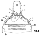
図1及び2からわかるように、固定部分3は、好ましくは、雌ねじ31を備える回転対称のねじ付リングの形をした本体30を有する。この雌ねじ31を用いて、乳首ユニットを、瓶又は飲用カップ、とりわけ哺乳瓶のねじ付ネック部上にねじ留めすることができる。固定部分3は、乳首部の方を向く上側部分に、内側にずれて上方に延びる受入リング32を有する。受入リングの下面は、一方で、瓶又は飲用カップのねじ付ネック部のための当接部として機能する。他方、受入リングの側方内壁は、乳首部1の射出形成(Anspritzen)のための接触面を形成する。
As can be seen from FIGS. 1 and 2, the fixing
支持体2は、実質的にドーム形の中空本体20を有する。この本体20は、その周囲に均一に分布して配置される凹所22を有する。この実施例では、これらは通り穴22である。これらは図7にはっきりと見てとることができる。凹所22は、好ましくは長円形であり、その長手方向軸は支持体2の外形線に沿って上から下へと延びる。この実施例では、凹所22はすべて同じ高さに配置されており、すべて同じ大きさである。好ましくは4〜7個の、とりわけ5個の凹所22がある。しかしながら、凹所22はまた、異なる高さに配置してもよいし、及び/又は異なる大きさ及び/又は異なる形であってもよい。
The
ドーム形の本体20の上部領域には、中央開口部があり、これを通って、飲用容器(図示せず)からの乳が乳首部1の吸い込み路14へと吸い込まれる。この中央開口部は比較的大きな直径を有する。好ましくは、吸い込み路14の内径にほぼ相当する大きさである。中央開口部は、好ましくは、固定手段により囲まれる。固定手段は、逆止め弁又はその一部を固定する。この実施例では、係止フック23があり、このフックに弁プレート4が係止される(図1及び6参照)。
The upper region of the dome-shaped
この例示の実施形態では、図1,5及び7から明らかなように、弁プレート4は丸く、閉じた形状である。弁プレートは、中央隆起部41を備えた平らなリングを有し、この隆起部の外側の上面は、下記の弁ダイヤフラム15のためのシール面を形成する。このプレートは、好ましくは、硬い又は堅い、及び/又は寸法安定性があり、ポリプロピレン(PP)、ポリアミド又は他の熱可塑性プラスチックからなる。
In this exemplary embodiment, the
弁プレート4が閉じた形状である場合、弁プレートは支持体2の上壁から距離をおいた場所で係止され、貫流路が、支持体2の内部ひいては飲用容器から、中央開口部ひいては吸い込み路14へと乳を流すために存在する。弁プレート4に穴が設けられている場合、これらの穴が代替的又は付加的な貫流路として働く。これらの穴はプレート上に分配されていてもよいし、周辺に配置されてもよい。穴は1つだけでもよい。
When the
支持体2の下側領域は、固定部分3の受入リング32の内径より小さい外径を有する。支持体2は受入リング32内に突き出す。隙間は乳首部1により埋められ、乳首部は、特に射出形成により、受入リング32と支持体2の下部外側周囲の両方と固定的に接続される。このため、図1,2及び3から明らかなように、乳首部は接続リング13を有する。この接続リング13には、図3から明らかなように、貫通孔24が設けられる。貫通孔は通気開口部として働き、吸い込み休止時、外部からの空気を、ねじ付リング30の雌ねじ31とドーム形支持体2の中央上方開口部とを介して飲用カップ内に入れることができるようにする。
The lower region of the
接続リング13は、ドーム型の本体11へと移り、マウスピース10で終わる。マウスピース10は中空円筒形であるか、又はわずかに円錐切頭形であり、吸い込み路14を形成する。マウスピースの自由端部は、吸い込み開口部17を形成し、この開口部は吸い込み路14につながる。吸い込み路14は、好ましくは、全長にわたって実質的には狭窄しておらず、比較的広い。通常、吸い込み路14の内径の値は、3〜12mmであり、特には9.2mmである。その長さに関しては、10〜30mm、特には18mmである。これは、赤ん坊がその口にマウスピース10を完全に入れることができるような長さであることが好ましい。
The
吸い込み開口部17は、吸い込み路14の横断面と同じく、好ましくは、少なくともほぼ丸く又は多角形である。その直径は、好ましくは2〜11mm、特には6.8mmである。好ましくは、吸い込み路14の直径よりわずかに小さい。
The
乳首部1の本体11は支持体2に沿って延びる。本体11と支持体2はともに、吸乳中の赤ん坊のためのマウスサポートを形成し、赤ん坊の唇又は口がこのマウスサポート上にのる。
The
本体11は、好ましくは、支持体2に固定的に接続されており、好ましくは上に射出形成される。しかしながら、この本体はまた、支持体上に固定せずにのっていてもよいし、又は数か所だけ支持体2に固定して接続されてもよい。
The
本体11は、好ましくは支持体2を完全に覆う。しかしながら、少なくとも凹所22を覆う。本体11は実質的に一定の厚みを有することができる。しかしながら、本実施例では、本体は、支持体2の閉じた側面でより凹所22の領域でより厚く、これらのより厚いゾーン18が凹所22内に突き出る。このことは、図1及び2にはっきりと見ることができる。閉じた側面の領域における本体11の厚みは通常、0.5〜3mmであり、とりわけ0.9mmである。凹所22の領域の厚みは0.7〜5mm、特に1.4mmである。
The
本体11からマウスピース10への移行領域、すなわち、吸い込み路14の最下部領域には、乳首部1の内壁に一体的に、弁ダイヤフラム15が形成される。これは、円周状の先の尖った密閉へりを備えた中央のダイヤフラム開口部16を有する。この密閉へりは弁プレート4の上述のシール面41上にのる。弁プレート4は、好ましくは、ダイヤフラム15をわずかに上向きに押し、ダイヤフラムに予張力がかかる。弁ダイヤフラム15と弁プレート4が逆止め弁5を形成する。ダイヤフラム開口部16は乳又は液体のための流量制限器を形成する。
A
図1では、逆止め弁は閉じられている。これは、乳首ユニットがまだ使用されてない状態に対応する。弁はまた、赤ん坊が吸い込んでいない休止時には閉じ、その結果、乳の流れを直ぐに中断でき、赤ん坊は息を詰まらせることがない。図2は吸い込み時の状況を示す。逆止め弁が開くと乳が吸い込み路に流れ込むことが可能となる。柔軟で可撓性のマウスピースは、通常、使用時赤ん坊の口中で変形される。これは図には示していない。 In FIG. 1, the check valve is closed. This corresponds to the situation where the nipple unit is not yet used. The valve also closes at rest when the baby is not inhaling, so that the flow of milk can be interrupted immediately and the baby will not choke. FIG. 2 shows the situation during inhalation. When the check valve is opened, milk can flow into the suction path. Soft and flexible mouthpieces are usually deformed in the baby's mouth during use. This is not shown in the figure.
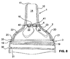
図8〜11は、本発明の乳首ユニットの第2の例示の実施形態を示す。この乳首ユニットは、基本的には第1の例示実施形態と同じ構造をしており、両実施例に同一の部分についての説明はここでは繰り返さない。しかしながら、第1の実施例とは異なり、支持体2と固定部分3がここでは互いと直接的に接続される。これらはともに一部品として製造され、同じ材料からなる単一の部品から構成される。この目的に適切な材料は、やはり、ポリプロピレン(PP)、ポリアミド又は他の熱可塑性プラスチックである。支持体2と固定部分3はこの場合も、硬い又は堅い、及び/又は寸法安定性がある。
8-11 show a second exemplary embodiment of the nipple unit of the present invention. The nipple unit basically has the same structure as that of the first exemplary embodiment, and the description of the same parts in both examples will not be repeated here. However, unlike the first embodiment, the
支持体2と固定部分3との間の固定した移行領域は、円周状の閉じられた移行フランジ21により形成され、好ましくはこれら2つの部分の縦軸に対し垂直に延びる。この移行フランジ21は、2,3の個別の貫通孔33を除いて、好ましくは完全に閉じた面を形成する。
The fixed transition region between the
この場合もまた、支持体2は、乳首部1の本体11によって囲まれている。この場合もまた、乳首部1は好ましくは射出形成又は上に射出形成される(an- oder aufgespritzt)。その場合、乳首部は、貫通孔33を通り抜け、ねじ付リング30の内側に閉じたリングを形成する。このリングは、密閉効果を有する。
Again, the
弁プレート4は、ここでもやはり閉じている。しかしながら、この実施例ではまた、弁プレートが通り穴を有することもできる。
The
図12〜16は、第3の例示の実施形態を示す。これは、基本的には第2の例示の実施形態と同じ構造である。ここでもまた、支持体2と固定部分3は単一の部分を形成する。これらは、互いに固定されて直接的に接続され、一部品として形成される。
12-16 illustrate a third exemplary embodiment. This is basically the same structure as the second exemplary embodiment. Again, the
しかしながら、上述の弁プレート4とは異なり、この場合は挿入要素5が存在する。挿入要素5を図12に示す。この挿入要素は、ドーム形の本体50を有し、これが支持体2の内面から距離をおいて配置される(図13及び14参照)。
However, unlike the
第1の挿入要素5の上端には、回転できないようにするための放射状に突出する突起53と、係止リブ54とがあり、この係止リブは支持体2の上部領域にある対応する係止手段に係合し、支持体2に第1の挿入要素5を固定する。本体50の下端には、完全に環状のフランジ57があり、これには、突出する円周状のリブ58が設けられる。これらリブ58は、本体20に対し回転できないように、途切れ部580を備えている。
At the upper end of the
本体50の上端部上には、平らなシール面55があり、流量制限器及び逆止め弁の弁ダイヤフラム15のための支持面を提供する。このシール面55は、乳用の貫流開口部56により囲まれる。
On the top end of the
本体50の側面には、側面開口部52があり、これは好ましくは同じく長円形であり、その長手方向軸は好ましくは上から下に延びている。
On the side of the
この挿入要素5は、好ましくは硬く又は堅く、好ましくは、ポリプロピレン(PP)、ポリアミド又は他の熱可塑性プラスチックからなる。
This
図13及び14に示すように、側面開口部52は、通気ダイヤフラム51により閉じられる。このダイヤフラム51は図12には示していない。ダイヤフラム51は本体50に固定され、好ましくはそこに射出形成される。好ましくは、シリコーン、シリコーン系プラスチック、ゴム、柔らかい熱可塑性エラストマー(TPE)又は他の熱可塑性プラスチックからなる。挿入要素5及びダイヤフラム51は、ここでもまた、例えば、2成分射出成形法で製造することができる。
As shown in FIGS. 13 and 14, the
柔軟なダイヤフラム51は、好ましくは、軟質材料がフランジ57の下側で円周状リング59として延びるように射出形成される。リング59は密閉作用を有する。
The
ダイヤフラム51は中央通気開口部510を有し、この開口部は先の尖った密閉へりにより囲まれる。この密閉へりを用いて、ダイヤフラム51は支持体2のシール面26に当たる。これは図15にはっきりと見ることができる。ねじ付リング30の雌ねじ31と、フランジ57と本体20の間の空気路Lとを介して、通気ダイヤフラム51まで通気される。これは図15及び16にはっきりと見ることができる。少なくとも1つの放射状内側に突出する突起25が、本体20に一体的に形成され、この場合、このような突起25が複数あり、これらが途切れ部580に係合する。この構造は、回転しないように固定すること及び同時に通気に役立つ。
この挿入部はまた、弁プレート4の代わりに、図1〜7による第1の実施形態でも使用することができる。好ましくは、その場合、第1の実施例において、第3の実施例による支持体2の形状、特に支持体2の肥厚部25とシール面26の領域の形状が適用される。
This insert can also be used in the first embodiment according to FIGS. 1 to 7 instead of the
この実施形態では、逆止め弁及び通気弁のダイヤフラムは、好ましくは、乳首ユニットが瓶上にねじ留めされるときに初めて予張力をうける。 In this embodiment, the check valve and vent valve diaphragms are preferably pre-tensioned only when the nipple unit is screwed onto the bottle.
本発明による乳首ユニットは、できるだけ自然な吸い込み動作を可能にする。しかしながら、本乳首ユニットは、構造が簡単で、それゆえ、安価に製造できるため、一度使用した後に廃棄できることを意味する。 The teat unit according to the present invention enables as natural a suctioning action as possible. However, this nipple unit is simple in construction and therefore can be manufactured inexpensively, meaning that it can be discarded after being used once.
1 乳首部
10 マウスピース
11 本体
13 接続リング
14 吸い込み路
15 弁ダイヤフラム
16 ダイヤフラム開口部
17 吸い込み開口部
18 肥厚ゾーン
19 リング
2 支持体
20 本体
21 移行フランジ
22 凹所
23 係止フック
24 通気開口部
25 肥厚領域
26 シール面
3 固定部分
30 本体
31 雌ねじ
32 受入リング
33 貫通孔
4 弁プレート
40 平面リング
41 隆起部
5 第1の挿入要素
50 本体
51 通気ダイヤフラム
510 通気開口部
52 側面開口部
53 回転防止のための突起
54 係止リブ
55 シール面
56 乳用貫流開口部
57 フランジ
58 リブ
580 途切れ部
59 リング
6 第2の挿入要素
60 本体
61 固定フランジ
62 弁ダイヤフラム
63 ダイヤフラム開口部
L 空気路
DESCRIPTION OF SYMBOLS 1
2
3 fixed
4
5
6 Second Insertion Element 60 Main Body 61 Fixed Flange 62 Valve Diaphragm 63 Diaphragm Opening
L air passage
Claims (16)
Nipple unit according to claim 5, wherein there are exactly five recesses (22).
Applications Claiming Priority (3)
| Application Number | Priority Date | Filing Date | Title |
|---|---|---|---|
| CH571/11 | 2011-03-29 | ||
| CH00571/11A CH704758A1 (en) | 2011-03-29 | 2011-03-29 | Teat. |
| PCT/CH2012/000067 WO2012129714A1 (en) | 2011-03-29 | 2012-03-22 | Teat unit |
Publications (2)
| Publication Number | Publication Date |
|---|---|
| JP2014513611A JP2014513611A (en) | 2014-06-05 |
| JP6010604B2 true JP6010604B2 (en) | 2016-10-19 |
Family
ID=44202529
Family Applications (1)
| Application Number | Title | Priority Date | Filing Date |
|---|---|---|---|
| JP2014501385A Expired - Fee Related JP6010604B2 (en) | 2011-03-29 | 2012-03-22 | Nipple unit |
Country Status (18)
| Country | Link |
|---|---|
| US (2) | US8910809B2 (en) |
| EP (1) | EP2691066B1 (en) |
| JP (1) | JP6010604B2 (en) |
| KR (1) | KR101940684B1 (en) |
| CN (1) | CN103501754B (en) |
| AU (1) | AU2012234677B2 (en) |
| BR (1) | BR112013025089A2 (en) |
| CA (1) | CA2830736C (en) |
| CH (1) | CH704758A1 (en) |
| ES (1) | ES2569186T3 (en) |
| HK (1) | HK1192445A1 (en) |
| IL (1) | IL228453A (en) |
| MX (1) | MX343258B (en) |
| MY (1) | MY164184A (en) |
| PL (1) | PL2691066T3 (en) |
| RU (1) | RU2600706C2 (en) |
| SG (1) | SG193425A1 (en) |
| WO (1) | WO2012129714A1 (en) |
Families Citing this family (13)
| Publication number | Priority date | Publication date | Assignee | Title |
|---|---|---|---|---|
| US20110178550A1 (en) * | 2009-08-18 | 2011-07-21 | Tesini David A | Varied Response Teether |
| CA148267S (en) * | 2012-04-30 | 2013-12-03 | Magic Love Ltd | Rubber nipple |
| US9295350B2 (en) | 2012-09-10 | 2016-03-29 | Mattel, Inc. | Sippy cup soft spout and method of forming the same |
| US9060592B2 (en) * | 2012-11-28 | 2015-06-23 | Specialized Bicycle Components, Inc. | Water bottle with poppet valve |
| EP3409610B1 (en) | 2014-01-31 | 2022-09-21 | Specialized Bicycle Components, Inc. | Water bottle with self-closing valve |
| BE1022555B1 (en) * | 2014-10-23 | 2016-06-01 | Materni Bvba | Tool for cup feeding |
| CN107616921A (en) * | 2016-07-15 | 2018-01-23 | 广州市华怡橡塑制品有限公司 | A kind of soft or hard binding silica gel nipple and its manufacture method |
| EP3388045A1 (en) | 2017-04-10 | 2018-10-17 | Koninklijke Philips N.V. | Teat for use with a container for containing a fluid |
| US20200077623A1 (en) * | 2018-09-10 | 2020-03-12 | Bertrand Dumont | Nipple System for Delivering Fluid to an Animal |
| WO2020065389A2 (en) * | 2018-09-24 | 2020-04-02 | Health And Happiness (H&H) Hong Kong Limited | Multiflow teat-ring for baby bottle and baby bottle comprising same |
| EP3878427A1 (en) * | 2020-03-13 | 2021-09-15 | Koninklijke Philips N.V. | Partitioning component for a feeding bottle |
| US11471379B2 (en) * | 2020-10-29 | 2022-10-18 | Momtech Inc. | Infant suckling device |
| US20240065941A1 (en) * | 2022-08-23 | 2024-02-29 | Proxamama, Inc. | Flow control valve for infant feeding device |
Family Cites Families (48)
| Publication number | Priority date | Publication date | Assignee | Title |
|---|---|---|---|---|
| US686109A (en) * | 1900-01-05 | 1901-11-05 | Ferdinand Muelhens | Nipple. |
| US990662A (en) * | 1909-08-05 | 1911-04-25 | William Macglashan | Device for regulating the flow of liquid from nursing-bottles. |
| US1605427A (en) | 1923-10-16 | 1926-11-02 | Anna M Delmas | Nursing nipple |
| US2584359A (en) * | 1947-10-03 | 1952-02-05 | Lawrence D Miles | Nipple and dispensing device |
| US2747573A (en) * | 1954-07-16 | 1956-05-29 | Owens Illinois Glass Co | Valved nursing nipple |
| US2960088A (en) * | 1959-02-16 | 1960-11-15 | Nursmatic Corp | Nipple for baby nursing bottle |
| US3516564A (en) * | 1969-01-30 | 1970-06-23 | Aluminum Co Of America | Nipple assembly and package |
| US3593870A (en) * | 1969-02-03 | 1971-07-20 | Dave Chapman Goldsmith & Yamas | Closure for fluid container |
| DE2219909C2 (en) | 1972-04-22 | 1973-09-20 | Mapa Gmbh Gummi- Und Plastikwerke, 3000 Hannover | One-piece teat |
| US4676386A (en) * | 1984-11-21 | 1987-06-30 | Royal American Industries, Inc. | Nipple |
| GB8503140D0 (en) * | 1985-02-07 | 1985-03-13 | Wyeth John & Brother Ltd | Teat unit |
| GB8526456D0 (en) | 1985-04-23 | 1985-11-27 | L S R Baby Products U K Ltd | Nipple |
| JP2741868B2 (en) * | 1988-06-13 | 1998-04-22 | ピジョン株式会社 | Nipples with caps for baby bottles |
| JPH02161950A (en) * | 1988-12-15 | 1990-06-21 | Jiekusu Kk | Nipple |
| FR2705561B1 (en) * | 1993-04-23 | 1995-08-04 | Glories Serge | Improved bottle teat. |
| DK0722308T3 (en) * | 1993-09-17 | 2000-05-29 | Baby Pack Holding Aps | Suction unit and method for making the suction unit |
| US5553726A (en) | 1993-11-08 | 1996-09-10 | Park; Ki H. | Dripless feeder nipple system with detachable valve |
| DE19520540C2 (en) * | 1995-06-03 | 2002-02-28 | Mapa Gmbh Gummi Plastikwerke | Method of making a teat for attachment to bottles |
| US6286697B1 (en) * | 1995-07-25 | 2001-09-11 | Jott Australia Pty. Ltd. | Nursing teat and teat and bottle assembly |
| JPH0956787A (en) * | 1995-08-25 | 1997-03-04 | Ten-Shan Wu | Structure of nipple |
| US5791503A (en) | 1996-02-05 | 1998-08-11 | Lyons; Richard A. | Nursing bottle with anti-air ingestion valve |
| US6032810A (en) * | 1997-07-17 | 2000-03-07 | Gerber Products Company | One-piece nipple/collar for nursers and the like |
| US6161710A (en) | 1997-11-03 | 2000-12-19 | Dieringer; Mary F. | Natural nipple baby feeding apparatus |
| GB9903554D0 (en) * | 1999-02-16 | 1999-04-07 | Jackel Int Pty Ltd | A drinking vessel |
| US20020063103A1 (en) * | 1999-12-13 | 2002-05-30 | Kathleen Kiernan | Nipple for nursing bottle |
| GB0022345D0 (en) | 2000-09-12 | 2000-10-25 | Jackel Int Ltd | A drinking vessel |
| NO316506B1 (en) * | 2001-06-05 | 2004-02-02 | Kjetil Naesje | Device by a valve for a beverage container and method for using the valve device |
| CA2456542C (en) | 2001-08-09 | 2010-10-19 | The First Years Inc. | Nipple for a baby bottle |
| AU2003275742B2 (en) * | 2002-10-29 | 2006-10-12 | Smartseal As | An opening-force maximizing device of an underpressure-activated valve for a drinking container |
| US20060011571A1 (en) * | 2002-11-08 | 2006-01-19 | Silver Brian H | Artificial nipple with reinforcement |
| US6923337B2 (en) * | 2003-08-27 | 2005-08-02 | The First Years Inc. | Drinking container |
| NO323158B1 (en) * | 2003-09-16 | 2007-01-08 | Smartseal As | Device at a valve for a drinking vessel |
| AT501841B1 (en) * | 2003-10-23 | 2007-01-15 | Bamed Ag | BOTTLE, IN PARTICULAR BABY BOTTLE, AND METHOD OF MANUFACTURING THEREOF |
| US7070065B2 (en) * | 2004-03-10 | 2006-07-04 | Fu Hong Industries Limited | Closure assembly for drinking vessel |
| JP4035574B2 (en) * | 2004-04-07 | 2008-01-23 | 株式会社パタカラ | Mouthpiece for baby bottle |
| JP4925295B2 (en) * | 2004-07-29 | 2012-04-25 | ピジョン株式会社 | Artificial nipple, baby bottle, and method for manufacturing artificial nipple |
| US20060081551A1 (en) * | 2004-10-20 | 2006-04-20 | Hegg Linda M | Nipple assemblies manufactured to fit standard externally-threaded necks of bottles |
| US7537128B2 (en) * | 2004-11-29 | 2009-05-26 | Amir Nachumi | Nursing bottle vent system |
| US7287657B1 (en) * | 2005-03-28 | 2007-10-30 | Ernest L Rodriguez | Triple seal disposable baby bottles |
| WO2007137440A2 (en) * | 2006-05-26 | 2007-12-06 | Medela Holding Ag | Teat for feeding bottles |
| WO2007137436A1 (en) * | 2006-05-26 | 2007-12-06 | Medela Holding Ag | Teat for feeding bottles |
| RU65759U1 (en) * | 2007-04-04 | 2007-08-27 | Санкт-Петербургский государственный университет | Nipple for breastfeeding |
| CH698956A1 (en) | 2008-06-12 | 2009-12-15 | Medela Holding Ag | Teat. |
| WO2009149757A1 (en) | 2008-06-12 | 2009-12-17 | Telefonaktiebolaget Lm Ericsson (Publ) | Method and arrangement in a telecommunication system |
| WO2009149573A1 (en) * | 2008-06-12 | 2009-12-17 | Medela Holding Ag | Suction teat |
| WO2010046812A1 (en) * | 2008-10-22 | 2010-04-29 | Koninklijke Philips Electronics N.V. | A teat |
| CH701676A1 (en) * | 2009-08-20 | 2011-02-28 | Medela Holding Ag | Teat. |
| BE1021890B1 (en) * | 2014-06-17 | 2016-01-25 | Materni Bvba | SPEAKING WITH CONFIRMATION RING |
-
2011
- 2011-03-29 CH CH00571/11A patent/CH704758A1/en not_active Application Discontinuation
-
2012
- 2012-03-22 PL PL12712054T patent/PL2691066T3/en unknown
- 2012-03-22 CN CN201280016602.5A patent/CN103501754B/en active Active
- 2012-03-22 KR KR1020137025598A patent/KR101940684B1/en active IP Right Grant
- 2012-03-22 SG SG2013068648A patent/SG193425A1/en unknown
- 2012-03-22 BR BR112013025089A patent/BR112013025089A2/en not_active Application Discontinuation
- 2012-03-22 JP JP2014501385A patent/JP6010604B2/en not_active Expired - Fee Related
- 2012-03-22 MX MX2013010951A patent/MX343258B/en active IP Right Grant
- 2012-03-22 AU AU2012234677A patent/AU2012234677B2/en not_active Ceased
- 2012-03-22 WO PCT/CH2012/000067 patent/WO2012129714A1/en active Application Filing
- 2012-03-22 EP EP12712054.1A patent/EP2691066B1/en active Active
- 2012-03-22 RU RU2013144671/15A patent/RU2600706C2/en not_active IP Right Cessation
- 2012-03-22 ES ES12712054.1T patent/ES2569186T3/en active Active
- 2012-03-22 CA CA2830736A patent/CA2830736C/en not_active Expired - Fee Related
- 2012-03-22 MY MYPI2013701711A patent/MY164184A/en unknown
- 2012-03-28 US US13/432,162 patent/US8910809B2/en active Active
-
2013
- 2013-09-16 IL IL228453A patent/IL228453A/en active IP Right Grant
-
2014
- 2014-06-13 HK HK14105627.4A patent/HK1192445A1/en not_active IP Right Cessation
- 2014-11-24 US US14/551,328 patent/US9840032B2/en active Active
Also Published As
| Publication number | Publication date |
|---|---|
| RU2600706C2 (en) | 2016-10-27 |
| WO2012129714A1 (en) | 2012-10-04 |
| EP2691066A1 (en) | 2014-02-05 |
| US20120248056A1 (en) | 2012-10-04 |
| RU2013144671A (en) | 2015-05-10 |
| SG193425A1 (en) | 2013-10-30 |
| MX2013010951A (en) | 2014-08-22 |
| AU2012234677B2 (en) | 2015-07-09 |
| IL228453A0 (en) | 2013-12-31 |
| MY164184A (en) | 2017-11-30 |
| CA2830736C (en) | 2018-11-20 |
| PL2691066T3 (en) | 2016-08-31 |
| US20150076733A1 (en) | 2015-03-19 |
| CN103501754A (en) | 2014-01-08 |
| ES2569186T3 (en) | 2016-05-09 |
| JP2014513611A (en) | 2014-06-05 |
| HK1192445A1 (en) | 2014-08-22 |
| KR101940684B1 (en) | 2019-01-21 |
| EP2691066B1 (en) | 2016-02-10 |
| CH704758A1 (en) | 2012-10-15 |
| KR20140009425A (en) | 2014-01-22 |
| MX343258B (en) | 2016-10-31 |
| AU2012234677A1 (en) | 2013-09-26 |
| US8910809B2 (en) | 2014-12-16 |
| US9840032B2 (en) | 2017-12-12 |
| CN103501754B (en) | 2017-02-15 |
| BR112013025089A2 (en) | 2017-02-14 |
| CA2830736A1 (en) | 2012-10-04 |
| IL228453A (en) | 2017-04-30 |
Similar Documents
| Publication | Publication Date | Title |
|---|---|---|
| JP6010604B2 (en) | Nipple unit | |
| JP5612569B2 (en) | Nipple | |
| JP5650741B2 (en) | Nipple unit | |
| JP5346280B2 (en) | Baby bottle nipple | |
| JP4964879B2 (en) | Artificial nipple with reinforcement | |
| US20110155684A1 (en) | Baby bottle and feeding system | |
| KR100549468B1 (en) | Functional bottle | |
| KR20070045702A (en) | Disposable air inlet bottle |
Legal Events
| Date | Code | Title | Description |
|---|---|---|---|
| A621 | Written request for application examination |
Free format text: JAPANESE INTERMEDIATE CODE: A621 Effective date: 20150129 |
|
| A131 | Notification of reasons for refusal |
Free format text: JAPANESE INTERMEDIATE CODE: A131 Effective date: 20151215 |
|
| A977 | Report on retrieval |
Free format text: JAPANESE INTERMEDIATE CODE: A971007 Effective date: 20151218 |
|
| A521 | Request for written amendment filed |
Free format text: JAPANESE INTERMEDIATE CODE: A523 Effective date: 20160307 |
|
| A131 | Notification of reasons for refusal |
Free format text: JAPANESE INTERMEDIATE CODE: A131 Effective date: 20160524 |
|
| A521 | Request for written amendment filed |
Free format text: JAPANESE INTERMEDIATE CODE: A523 Effective date: 20160708 |
|
| TRDD | Decision of grant or rejection written | ||
| A01 | Written decision to grant a patent or to grant a registration (utility model) |
Free format text: JAPANESE INTERMEDIATE CODE: A01 Effective date: 20160830 |
|
| A61 | First payment of annual fees (during grant procedure) |
Free format text: JAPANESE INTERMEDIATE CODE: A61 Effective date: 20160916 |
|
| R150 | Certificate of patent or registration of utility model |
Ref document number: 6010604 Country of ref document: JP Free format text: JAPANESE INTERMEDIATE CODE: R150 |
|
| R250 | Receipt of annual fees |
Free format text: JAPANESE INTERMEDIATE CODE: R250 |
|
| LAPS | Cancellation because of no payment of annual fees |