JP6009331B2 - Mounting device for electronic equipment - Google Patents
Mounting device for electronic equipment Download PDFInfo
- Publication number
- JP6009331B2 JP6009331B2 JP2012255806A JP2012255806A JP6009331B2 JP 6009331 B2 JP6009331 B2 JP 6009331B2 JP 2012255806 A JP2012255806 A JP 2012255806A JP 2012255806 A JP2012255806 A JP 2012255806A JP 6009331 B2 JP6009331 B2 JP 6009331B2
- Authority
- JP
- Japan
- Prior art keywords
- holder
- electronic device
- attachment
- stand
- back plate
- Prior art date
- Legal status (The legal status is an assumption and is not a legal conclusion. Google has not performed a legal analysis and makes no representation as to the accuracy of the status listed.)
- Active
Links
Images


Description
本発明は、電気測定器などの電子機器をテーブルもしくは壁面に設置するために用いられる電子機器用マウント装置に関し、さらに詳しく言えば、スタンドでの使用時においては、その設置角度の調節を簡単に行うことができる電子機器用マウント装置に関する。 The present invention relates to an electronic device mounting apparatus used for installing an electronic device such as an electric measuring instrument on a table or a wall surface. More specifically, the mounting angle can be easily adjusted when used on a stand. The present invention relates to a mounting apparatus for electronic equipment.
電気測定器などの各種電子機器には、計測中のモニターを観察しやすくするためにスタンドを備えているものが多い。例えば特許文献1には、電子機器の背面に沿って引き起こし式のスタンドを備えており、このスタンドを引き起こすことで、電子機器本体を自立状態で立て掛けることが記載されている。 Many electronic devices such as electric measuring instruments are provided with a stand to facilitate observation of the monitor being measured. For example, Patent Document 1 describes that a raising-type stand is provided along the back surface of the electronic device, and the electronic device main body is stood in a self-standing state by causing the stand.
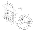
また、これとは別に壁掛け、スタンド両用として用いられるマウント装置もある。図8に示すように、このマウント装置100は、電子機器101(図9参照)に着脱自在に取り付けられるホルダー200と、このホルダー200に対して着脱自在に取り付けられるスタンド300とを備えている。
In addition to this, there is also a mount device used for both wall hanging and stand. As shown in FIG. 8, the
ホルダー200は、電子機器101の背面を支持する背板201と、電子機器101の底面を支持する底板202と、電子機器101の前面の一部を支持する前板203とが一体にL字状に形成されている。背板201の幅方向の両端には、電子機器101の側面の押さえる側板204,204が設けられている。
In the
ホルダー200の背板の四隅には、電子機器101を壁掛け支持するために用いられるだるま孔205が4カ所設けられている。背板201には、スタンド300をネジ止めするためのネジ止め孔206が設けられている。
In the four corners of the back plate of the
スタンド300は、1枚の金属板をくの字に折り曲げて形成された、長さの異なる2種類のスタンド片301,302を備えている。各スタンド片301,302には、ネジ止め用の穿孔303が設けられている。
The
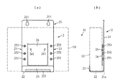
これによれば、壁掛け時にはホルダー200のみが用いられるが、スタンドとして使用する場合には、図9(a)に示すように、短い方のスタンド片302をホルダー200側に取り付け、長い方のスタンド片301を脚部として被設置面に置くことで、電子機器101を被設置面に対して第1傾斜角として例えば60°程度傾けた状態で支持することができる。
According to this, only the
これに対して、図9(b)に示すように、長い方のスタンド片301をホルダー200側に取り付け、短い方のスタンド片302を脚部として被設置面に置くことにより、電子機器101を被設置面に対して第2傾斜角として例えば40°程度傾けた状態で支持することができる。
On the other hand, as shown in FIG. 9B, the
しかしながら、この着脱式のマウント装置100には、次のような課題があった。すなわち、通常、電子機器101の背面には電池ケースの蓋が設けられていることが多いが、電子機器101の背面を塞ぐようにホルダー200の背板201がネジ止めされているため、電池交換するには、ホルダー200をいちいち取り外さなくてはならない。
However, the
また、ホルダー200が電子機器101を抱え込むように装着されているため、振動が発生する場所などに置くと、振動によって電子機器101とホルダー200とが擦れ合うという問題もある。さらには、設置角を2種類とするため、スタンド300のスタンド片301,302の長さを変えているが、嵩張るし、重量も大きくなるため好ましくない。
In addition, since the
そこで、本発明の課題は、壁掛け、スタンド両用であり、電子機器をしっかりと固定でき、かつ、スタンドでの使用時には傾斜角度を使い分けに応じて容易に変更することができる電子機器用マウント装置を提供することにある。 Therefore, an object of the present invention is to mount both a wall mount and a stand, an electronic apparatus mounting device that can firmly fix an electronic apparatus and can easily change an inclination angle according to proper use when used with a stand. It is to provide.
上述した課題を解決するため、本発明の電子機器用マウント装置は、電子機器を着脱自在に保持して所定の壁面に取り付ける壁掛け用のアタッチメントホルダーと、被設置面上において上記電子機器を上記アタッチメントホルダーを介して所定角度傾けた状態で支持するスタンドとを含み、上記スタンドは、上記被設置面に載置される脚部と、上記脚部から所定の角度で立ち上がる支持部とを備え、上記支持部には、上記脚部に対して異なる角度で傾斜する複数のホルダー支持面が形成されており、上記アタッチメントホルダーには、上記ホルダー支持面のうちの選択されたいずれか一つのホルダー支持面に対して所定の連結手段を介して着脱可能に取り付けられる取付面が設けられていることを特徴としている。 In order to solve the above-described problems, a mounting device for an electronic device according to the present invention includes an attachment holder for wall mounting that detachably holds the electronic device and attaches the electronic device to the attachment surface. A stand that is supported at a predetermined angle through a holder, and the stand includes a leg portion that is placed on the installation surface and a support portion that rises from the leg portion at a predetermined angle. The support portion is formed with a plurality of holder support surfaces that are inclined at different angles with respect to the leg portions, and the attachment holder has any one of the holder support surfaces selected from the holder support surfaces. An attachment surface that is detachably attached via a predetermined connecting means is provided.
また、上記各ホルダー支持面は、上記脚部側から先端側に向かうにつれて、その傾斜角が段階的に小さくなる多角面状に形成されていることを特徴としている。 Each of the holder support surfaces is formed in a polygonal shape whose inclination angle gradually decreases from the leg side toward the tip side.
さらには、上記連結手段として雄ネジが用いられ、上記支持部には、上記各ホルダー支持面ごとに上記雄ネジを反ホルダー支持面側から挿通するネジ挿通孔が穿設されているとともに、上記アタッチメントホルダーの上記取付面側には、上記雄ネジの相手としての雌ネジが設けられていることを特徴としている。 Furthermore, a male screw is used as the connecting means, and the support portion is provided with a screw insertion hole through which the male screw is inserted from the side opposite to the holder support surface for each holder support surface. A female screw as a counterpart of the male screw is provided on the attachment surface side of the attachment holder.
また、上記ホルダー支持面は、上記脚部側から先端側に向かうにつれて、上記脚部に対する接線勾配が連続的に小さくなる円弧面であって、上記ホルダー支持面には、上記連結手段としての雄ネジが挿通されるスリット溝が円弧面に沿って連続的に形成されているとともに、上記アタッチメントホルダーの上記取付面側には、上記雄ネジの相手としての雌ネジが備えられていることを特徴としている。 Further, the holder support surface is an arc surface in which a tangential gradient with respect to the leg portion continuously decreases from the leg side toward the tip end side, and the holder support surface is provided with a male as a connecting means. The slit groove into which the screw is inserted is formed continuously along the arc surface, and the attachment surface side of the attachment holder is provided with a female screw as a counterpart of the male screw. It is said.
また別の態様として、上記アタッチメントホルダーは、上記電子機器の背面側を支持する背板と、上記背板の底部からほぼ直角に折り曲げられて上記電子機器の底面を支持する底板とを含み、上記背板の一部分が上記取付面に割り当てられており、上記雌ネジは、上記各ネジ挿通孔と対応するように上記取付面の複数個所に設けられており、上記各雌ネジは、上記アタッチメントホルダーが上記各ホルダー支持面のいずれに取り付けられた際にも、上記背板の底部が上記脚部上に位置するように配置されていることを特徴としている。 As another aspect, the attachment holder includes a back plate that supports the back side of the electronic device, and a bottom plate that is bent at a substantially right angle from the bottom of the back plate and supports the bottom surface of the electronic device, A portion of the back plate is assigned to the mounting surface, and the female screws are provided at a plurality of locations on the mounting surface so as to correspond to the screw insertion holes, and the female screws are connected to the attachment holder. Is arranged such that the bottom portion of the back plate is positioned on the leg portion when it is attached to any of the holder support surfaces.
また、上記電子機器の背面には、凹部が形成されており、上記アタッチメントホルダーの背板には、上記凹部と係合するように上記背板の一部分を切り起こしてなる舌片状の係合部が設けられていることを特徴としている。 Further, a recess is formed on the back surface of the electronic device, and a tongue-like engagement formed by cutting and raising a part of the back plate to engage with the recess on the back plate of the attachment holder. It is characterized in that a part is provided.
また、上記電子機器の背面には、上記凹部以外の部分に電池収納部を開閉する電池蓋が設けられており、上記アタッチメントホルダーの背板は、上記電池蓋を避けるようにして上記電子機器の背面に当接されることを特徴としている。 In addition, a battery lid that opens and closes the battery housing portion is provided on the back surface of the electronic device at a portion other than the recess, and the back plate of the attachment holder avoids the battery lid. It is characterized by being in contact with the back surface.
本発明によれば、壁掛け時にはアタッチメントホルダーのみが用いられるが、スタンドでの使用時には、スタンドの脚部に対して異なる角度を有するホルダー支持面のいずれか1つの支持面を選択し、その支持面にアタッチメントホルダーを介して電子機器を取り付けることにより、電子機器本をユーザーにとって好ましい傾斜角に配置することができるばかりでなく、スタンドの構成をシンプルかつ軽量化できる。 According to the present invention, only the attachment holder is used when hanging on the wall, but when used on the stand, any one of the holder support surfaces having different angles with respect to the legs of the stand is selected and the support surface is selected. By attaching the electronic device via the attachment holder, the electronic device book can be arranged at an inclination angle preferable for the user, and the structure of the stand can be simplified and reduced in weight.
また、上記各ホルダー支持面は、上記脚部側から先端側に向かうにつれて、その傾斜角が段階的に小さくなる多角面状に形成されていることにより、傾斜角度の選択を容易に行うことができる。 In addition, since each of the holder support surfaces is formed in a polygonal shape in which the inclination angle gradually decreases from the leg side toward the distal end side, it is possible to easily select the inclination angle. it can.
さらには、上記連結手段として雄ネジが用いられ、上記支持部には、上記各ホルダー支持面ごとに上記雄ネジを反ホルダー支持面側から挿通するネジ挿通孔が穿設されているとともに、上記アタッチメントホルダーの上記取付面側には、上記雄ネジの相手としての雌ネジが設けられていることにより、スタンドに対してアタッチメントホルダーを容易に固定することができる。 Furthermore, a male screw is used as the connecting means, and the support portion is provided with a screw insertion hole through which the male screw is inserted from the side opposite to the holder support surface for each holder support surface. By providing a female screw as a counterpart of the male screw on the attachment surface side of the attachment holder, the attachment holder can be easily fixed to the stand.
また、上記ホルダー支持面は、上記脚部側から先端側に向かうにつれて、上記脚部に対する接線勾配が連続的に小さくなる円弧面であって、上記ホルダー支持面には、上記連結手段としての雄ネジが挿通されるスリット溝が円弧面に沿って連続的に形成されているとともに、上記アタッチメントホルダーの上記取付面側には、上記雄ネジの相手としての雌ネジが設けられていることにより、ホルダー支持面に沿って取付面を自在に動かすことができるため、傾斜角を所望とする位置に決めて固定することができる。 Further, the holder support surface is an arc surface in which a tangential gradient with respect to the leg portion continuously decreases from the leg side toward the tip end side, and the holder support surface is provided with a male as a connecting means. The slit groove through which the screw is inserted is continuously formed along the arc surface, and the attachment surface side of the attachment holder is provided with a female screw as the counterpart of the male screw, Since the attachment surface can be moved freely along the holder support surface, the inclination angle can be determined and fixed at a desired position.
また、上記電子機器の背面には、凹部が形成されており、上記アタッチメントホルダーの背板には、上記凹部と係合するように上記背板の一部分を切り起こしてなる舌片状の係合部が設けられていることにより、着脱可能な状態であっても、電子機器をがたつくことなくアタッチメントホルダーに安定して保持させることができる。 Further, a recess is formed on the back surface of the electronic device, and a tongue-like engagement formed by cutting and raising a part of the back plate to engage with the recess on the back plate of the attachment holder. By providing the part, the electronic device can be stably held by the attachment holder without rattling even in a detachable state.
上記電子機器の背面には、上記凹部以外の部分に電池収納部を開閉する電池蓋が設けられており、上記アタッチメントホルダーの背板は、上記電池蓋を避けるようにして上記電子機器の背面に当接されることにより、アタッチメントホルダーが装着されている状態のままで、電池蓋を開閉することができる。 A battery lid that opens and closes the battery compartment is provided in a portion other than the recess on the back surface of the electronic device, and a back plate of the attachment holder is disposed on the back surface of the electronic device so as to avoid the battery lid. By contacting, the battery cover can be opened and closed while the attachment holder is mounted.
次に本発明の一実施形態について図面を参照しながら説明するが、本発明はこれに限定されるものではない。 Next, an embodiment of the present invention will be described with reference to the drawings, but the present invention is not limited to this.
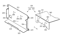
図1〜図4に示すように、この電子機器用マウント装置1は、電子機器10に着脱自在に取り付けられるアタッチメントホルダー2と、被設置面上に載置され、アタッチメントホルダー2を所定の角度で取り付けるためのスタンド3とを備えている。
As shown in FIGS. 1 to 4, the electronic device mounting apparatus 1 includes an
図4に示すように、この実施形態において電子機器10は、背面パネルに嵌合用の凹部11を有し、背面パネルにはさらに電池蓋12が設けられている。なお、電子機器10は、単なる箱形状として描画されているが、その種類や形状は、仕様に応じて任意に選択されてよく、各種電気測定器のほか、計測ロガーや無線送受信機であってもよい。
As shown in FIG. 4, in this embodiment, the
アタッチメントホルダー2は、電子機器10の背面を支持する背板21と、電子機器10の底面を支持する底板22と、電子機器10の底部側の前面を支持する前板23とを有し、それらが1枚の板体からJ字状に一体形成されている。この実施形態において、アタッチメントホルダー2は、金属板から構成されているが、樹脂製であってもよい。
The
背板21は、電子機器10の背面に沿って配置される矩形状を呈し、その中央には、電子機器10の背面パネルに形成された凹部11に合致する係合部24が設けられている。
The
係合部24は、一辺が背板21に連結するようにコ字状に切り欠いて形成される切り起し舌片で、電子機器10の背面に向けて出っ張るように、断面L字状に折り曲げたものからなる。係合部24には、電子機器10を固定するねじを挿通する挿通孔241が設けられている。
The engaging
この実施形態において、係合部24は、電子機器10の背面側に向かって出っ張るように形成されているが、電子機器10側が凸形状の場合、電子機器10の背面とは離反する方向に折り曲げられていてもよく、電子機器10側の係合部に対して合致する形状であればよい。
In this embodiment, the engaging
背板21の上端側には、アタッチメントホルダー2を介して電子機器10を壁掛け支持するために用いられるだるま孔211が背板21の上端の角部に2カ所に設けられている。だるま孔211の数や位置は仕様に応じて任意に変更されてよい。
On the upper end side of the
背板21には、後述するスタンド3の各ホルダー支持面32a〜32cに沿って合致する一対の取付面25,25が設けられている。この実施形態において、取付面25,25は、上述した係合部24を挟んで背板21の両側に配置されている。
The
取付面25,25には、各ホルダー支持面32a〜32cに対する固定手段としての第1〜第3雌ネジ251,252,253が設けられている。この実施形態において、各雌ネジ251〜253は、背板21に形成されたネジの挿通孔に沿って配置されたナットである。
The mounting surfaces 25 and 25 are provided with first to third
なお、この実施形態では、背板21の板厚が薄いため、ナットを雌ネジとして代用しているが、背板21の板厚が厚い場合には、挿通孔に直に雌ネジ山を形成することができるため、そのような場合には、ナットを省略することができる。
In this embodiment, since the plate thickness of the
底板22は、背板21の下端をほぼ直角に折り曲げて形成されており、その角部21aは、面取りされている。前板23は、底板22の先端を同様にほぼ直角に折り曲げて形成されており、その角部は同様に面取りされている。底板22と前板23にかけての一部には、軽量化のための切欠部221が形成されている。
The
次に、図3(a),(b)を参照して、スタンド3は、例えばテーブルなどの被設置面に載置される脚部31と、脚部31から所定の傾斜角を持って切り起こされた支持板32とを有し、それらが1枚の金属板の一部をコ字状に切り欠いて、引き起こすことにより形成されている。スタンド3は合成樹脂製であってもよい。
Next, referring to FIGS. 3 (a) and 3 (b), the
また、脚部31と支持板32とは別体で形成され、組み合わされたものであってもよい。その場合、脚部31と支持板32とを角度固定機能を有するヒンジで連結し、脚部31に対して支持板32を起伏自在としてもよい。これによれば、スタンド3が折り畳み可能とすることで、よりコンパクトにすることができる。
Further, the
図1を参照して、脚部31は、扁平なT状であって、その四隅には、被設置面に対して固定するためのネジ孔311が、この例では4カ所設けられている。脚部31の形状は任意であり、安定して被設置面に据え置くことができればよい。
With reference to FIG. 1, the
ネジ孔311は、図示しないネジを挿通するための挿通孔であるが、脚部31の裏面に滑り止めのゴムシートなどを貼り付けてもよいしい、両面粘着テープなどを用いて固定するようにしてもよい。
The
この実施形態において、支持板32は、基端側が脚部31に接続されたアーチ状に形成されている。図3(b)に示すように、支持板32は、基端側(図3(b)では下端側)から上端側に向かうにつれてその傾斜角が段階的に小さくなるように折り曲げられている。
In this embodiment, the
この実施形態において、支持板32は、脚部31に対して角度θ1=60°となるように折り曲げられた第1ホルダー支持面32aと、脚部31に対して角度θ2=50°となるように折り曲げられた第2ホルダー支持面32bと、脚部31に対して角度θ3=40°となるように折り曲げられた第3ホルダー支持面32cとを備えている。
In this embodiment, the
ホルダー支持面32a〜32cは3面に限らず、2面もしくは4面以上、または、それらの折り曲げ角度θも任意に選択されてよい。 The holder support surfaces 32a to 32c are not limited to three surfaces, and two or four or more surfaces, or their bending angles θ may be arbitrarily selected.
各ホルダー支持面32a〜32cには、アタッチメントホルダー2の取付面25に設けられた第1〜第3雌ネジ251〜253に合わせてネジ止めされるネジ挿通孔321が設けられている。この実施形態において、各ネジ挿通孔321は、各ホルダー支持面32a〜32cに1カ所ずつ配置されているが、数は任意であってよい。
Each
電子機器10を壁に掛ける場合には、アタッチメントホルダー2を図示しない壁面に固定して、電子機器10をアタッチメントホルダー2に保持させる。このとき、まず、電子機器10の背面に設けられた凹部11にアタッチメントホルダー2の係合部24を合致させることにより、電子機器10はアタッチメントホルダー2にがたつきなく保持させることができる。
When the
なお、電子機器10をアタッチメントホルダー2により確実に固定するには、挿通孔241,241を介して電子機器10とネジ止めしたうえで、アタッチメントホルダー2を壁面に取り付ければよい。
In order to securely fix the
次に、図5および図6を参照して、スタンドを使用する場合についての一例を説明する。本発明によれば、ユーザーは、アタッチメントホルダー2を好みの傾斜角を選んで取り付けることができる。
Next, an example of using a stand will be described with reference to FIGS. According to the present invention, the user can attach the
すなわち、角度60°で取り付けるには、図6(a)に示すように、第1ホルダー支持面32aのネジ挿通孔321と、取付面25の第1雌ネジ251とを位置合わせしたのち、雄ネジ33を取付面25の背面側から差し込んで、第1雌ネジ251に螺合すればよい。
That is, in order to attach at an angle of 60 °, as shown in FIG. 6A, the
同様に角度50°で取り付けるには、図6(b)に示すように、第2ホルダー支持面32bのネジ挿通孔321と、取付面25の第2雌ネジ252とを位置合わせしたのち、雄ネジ33を取付面25の背面側から差し込んで、第2雌ネジ252に螺合すればよい。
Similarly, for attachment at an angle of 50 °, the
また、角度40°で取り付けるには、図6(c)に示すように、第3ホルダー支持面32cのネジ挿通孔321と、取付面25の第3雌ネジ253とを位置合わせしたのち、雄ネジ33を取付面25の背面側から差し込んで、第3雌ネジ253に螺合すればよい。
In order to mount at an angle of 40 °, as shown in FIG. 6C, the
しかる後、電子機器10をアタッチメントホルダー2に保持させることで、ユーザーが希望する角度位置に合わせて電子機器10を取り付けることができる。なお、電子機器10に予めアタッチメントホルダー2を取り付けてから、スタンド3に取り付けてもよい。
Thereafter, the
この実施形態において、図6(a)〜(c)に示すように、第1〜第3雌ネジ251,252,253は、背板21と底板22との角部21aが、各角度ポジションにおいて常にスタンド3の脚部31に接した状態となるようにアタッチメントホルダー2とスタンド3とを固定できる位置に設けられている。
In this embodiment, as shown in FIGS. 6A to 6C, the first to third
これによれば、アタッチメントホルダー2がスタンド3から浮いたりすることなく、安定して固定することができる。
According to this, the
また、ホルダー支持面32の各ネジ挿通孔321を含むように延在するスリット溝とし、さらに取付面25にも各雌ネジ251〜253を含むように延在するスリット溝を設けておき、それらスリット溝同士が重なるように配置して、背面側から雄ねじを挿通して、反対側からナットで挟むようにように固定してもよい。
In addition, a slit groove extending so as to include each
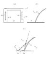
また、スタンド3の別の態様として、図7(a),(b)に示すように、支持板32を脚部31の基端側から他端側に向かって脚部31に対する接線勾配を漸次小さくなるように連続した円弧面状に形成し、その円弧面に沿ってスリット溝322を設けてもよい。この場合には、アタッチメントホルダー2側にもスリット溝が形成され、それらスリット溝同士が重なるように配置して、背面側から雄ねじを挿通して、反対側からナットで挟むようにように固定してもよい。
As another aspect of the
これによれば、図7(c)に示すように、アタッチメントホルダー2を支持板32の任意の位置で支えることにより、ユーザーが好みの角度位置で電子機器10を傾けることができる。
According to this, as shown in FIG. 7C, by supporting the
1 電子機器用マウント装置
10 電子機器
2 アタッチメントホルダー
21 背板
22 底板
23 前板
24 係合部
25 取付面
251〜253 第1〜第3雌ネジ
3 スタンド
31 脚部
32 支持板
32a〜32c 第1〜第3ホルダー支持面
DESCRIPTION OF SYMBOLS 1 Mount device for
Claims (6)
上記スタンドは、上記被設置面に載置される脚部と、上記脚部から所定の角度で立ち上がる支持部とを備え、上記支持部には、上記脚部に対して異なる角度で傾斜する複数のホルダー支持面が形成されており、
上記アタッチメントホルダーには、上記ホルダー支持面のうちの選択されたいずれか一つのホルダー支持面に対して所定の連結手段を介して着脱可能に取り付けられる取付面が設けられており、上記各ホルダー支持面は、上記脚部側から先端側に向かうにつれて、その傾斜角が段階的に小さくなる多角面状に形成されていることを特徴とする電子機器用マウント装置。 An attachment holder for hanging the electronic device to be detachably held and attached to a predetermined wall surface, and a stand that supports the electronic device on the installation surface in a state inclined at a predetermined angle via the attachment holder,
The stand includes a leg portion that is placed on the installation surface and a support portion that rises from the leg portion at a predetermined angle, and the support portion includes a plurality of inclined portions that are inclined at different angles with respect to the leg portion. Holder support surface is formed,
The aforementioned attachment holder, and mounting surface detachably attached via a predetermined connecting means are provided for the selected one of the holder supporting face of the holder supporting surface, each holder supporting The electronic device mounting apparatus according to claim 1, wherein the surface is formed in a polygonal shape in which the inclination angle gradually decreases from the leg side toward the tip side .
上記雌ネジは、上記各ネジ挿通孔と対応するように上記取付面の複数個所に設けられており、上記各雌ネジは、上記アタッチメントホルダーが上記各ホルダー支持面のいずれに取り付けられた際にも、上記背板の底部が上記脚部上に位置するように配置されていることを特徴とする請求項2に記載の電子機器用マウント装置。 The attachment holder includes a back plate that supports the back side of the electronic device, and a bottom plate that is bent at a substantially right angle from the bottom of the back plate to support the bottom surface of the electronic device, and a part of the back plate is the above-mentioned Assigned to the mounting surface,
The female screws are provided at a plurality of locations on the mounting surface so as to correspond to the screw insertion holes, and the female screws are mounted when the attachment holder is mounted on any of the holder support surfaces. The electronic apparatus mounting apparatus according to claim 2, wherein the bottom portion of the back plate is disposed so as to be positioned on the leg portion.
上記スタンドは、上記被設置面に載置される脚部と、上記脚部から所定の角度で立ち上がる支持部とを備え、上記支持部には、上記脚部に対して異なる角度で傾斜する複数のホルダー支持面が形成されており、
上記アタッチメントホルダーには、上記ホルダー支持面のうちの選択されたいずれか一つのホルダー支持面に対して所定の連結手段を介して着脱可能に取り付けられる取付面が設けられており、
上記ホルダー支持面は、上記脚部側から先端側に向かうにつれて、上記脚部に対する接線勾配が連続的に小さくなる円弧面であって、上記ホルダー支持面には、上記連結手段としての雄ネジが挿通されるスリット溝が円弧面に沿って連続的に形成されているとともに、上記アタッチメントホルダーの上記取付面側には、上記雄ネジの相手としての雌ネジが備えられていることを特徴とする電子機器用マウント装置。 An attachment holder for hanging the electronic device to be detachably held and attached to a predetermined wall surface, and a stand that supports the electronic device on the installation surface in a state inclined at a predetermined angle via the attachment holder,
The stand includes a leg portion that is placed on the installation surface and a support portion that rises from the leg portion at a predetermined angle, and the support portion includes a plurality of inclined portions that are inclined at different angles with respect to the leg portion. Holder support surface is formed,
The attachment holder is provided with an attachment surface that is detachably attached to any one of the holder support surfaces selected from the holder support surfaces via a predetermined connecting means,
The holder support surface is an arc surface in which a tangential gradient with respect to the leg portion continuously decreases from the leg side toward the tip side, and a male screw as the connection means is provided on the holder support surface. A slit groove to be inserted is continuously formed along an arc surface, and a female screw as a counterpart of the male screw is provided on the attachment surface side of the attachment holder. that electronic equipment mounted devices.
Priority Applications (1)
| Application Number | Priority Date | Filing Date | Title |
|---|---|---|---|
| JP2012255806A JP6009331B2 (en) | 2012-11-22 | 2012-11-22 | Mounting device for electronic equipment |
Applications Claiming Priority (1)
| Application Number | Priority Date | Filing Date | Title |
|---|---|---|---|
| JP2012255806A JP6009331B2 (en) | 2012-11-22 | 2012-11-22 | Mounting device for electronic equipment |
Publications (2)
| Publication Number | Publication Date |
|---|---|
| JP2014103332A JP2014103332A (en) | 2014-06-05 |
| JP6009331B2 true JP6009331B2 (en) | 2016-10-19 |
Family
ID=51025560
Family Applications (1)
| Application Number | Title | Priority Date | Filing Date |
|---|---|---|---|
| JP2012255806A Active JP6009331B2 (en) | 2012-11-22 | 2012-11-22 | Mounting device for electronic equipment |
Country Status (1)
| Country | Link |
|---|---|
| JP (1) | JP6009331B2 (en) |
Families Citing this family (1)
| Publication number | Priority date | Publication date | Assignee | Title |
|---|---|---|---|---|
| KR102230079B1 (en) * | 2019-04-29 | 2021-03-19 | 주식회사 교원 | Air cleaner system having a postionalbe control button according to install position |
Family Cites Families (6)
| Publication number | Priority date | Publication date | Assignee | Title |
|---|---|---|---|---|
| JPS61276509A (en) * | 1985-05-31 | 1986-12-06 | 山浦 正一 | Base plate support leg |
| JPH0727719Y2 (en) * | 1989-11-24 | 1995-06-21 | 三洋電機株式会社 | Desktop stand mounting device |
| JPH05281910A (en) * | 1992-04-03 | 1993-10-29 | Hitachi Ltd | Tilt angle varying device for display device |
| JP2557973Y2 (en) * | 1992-11-27 | 1997-12-17 | 明星電気株式会社 | Structure of charger for cordless telephone |
| JP2006308062A (en) * | 2005-05-02 | 2006-11-09 | Sharp Corp | Supporting mechanism |
| JP4892752B2 (en) * | 2009-03-30 | 2012-03-07 | Necインフロンティア株式会社 | Desktop and wall mounted devices for electronic equipment |
-
2012
- 2012-11-22 JP JP2012255806A patent/JP6009331B2/en active Active
Also Published As
| Publication number | Publication date |
|---|---|
| JP2014103332A (en) | 2014-06-05 |
Similar Documents
| Publication | Publication Date | Title |
|---|---|---|
| TW423965B (en) | Instrument with stand and hook | |
| KR20180103828A (en) | Connector for connecting an electronic musical instrument pedal to the pedal board | |
| US20190226635A1 (en) | Wall mount for an electronic display, computer arrangement and method of mounting an electronic display and a computer system to a wall | |
| WO2007008273A1 (en) | Shower rod assembly | |
| US20080006745A1 (en) | Hand-held electronic instrument with stand | |
| EP3267458A1 (en) | Planar switch and mounting method for same planar switch | |
| US20180255952A1 (en) | Curtain rod bracket | |
| JP6009331B2 (en) | Mounting device for electronic equipment | |
| US8488307B2 (en) | Point-of-sale system bracket and a point-of-sale system | |
| EP2551067B1 (en) | Tool positioning pad | |
| KR200475185Y1 (en) | Storage hanger for partition | |
| JP2007156176A (en) | Display device and stand for display device | |
| US20100163701A1 (en) | Supporting device for supporting a flat panel display device and flat panel display device assembly | |
| JP2010171177A (en) | Support device and electronic equipment | |
| JP5518439B2 (en) | Connection unit mounting structure and connection system | |
| EP2424235A1 (en) | System for mounting appliances behind a flat panel display | |
| JP6495596B2 (en) | lighting equipment | |
| TW201342012A (en) | Fixing device and the chassis assembly using the same | |
| JP6888756B2 (en) | Display panel mounting set | |
| JP2021041014A (en) | Fixture to wall surface | |
| JP6535227B2 (en) | Housing mounting structure | |
| JP3958329B2 (en) | Toilet paper holder installation plate | |
| EP2988051B1 (en) | Multifunctional fixture apparatus and assembly thereof | |
| JP2019050289A (en) | Fixing member | |
| USD583143S1 (en) | Utility housing with receptacles for handheld computer, laser measuring device, and camera |
Legal Events
| Date | Code | Title | Description |
|---|---|---|---|
| A621 | Written request for application examination |
Free format text: JAPANESE INTERMEDIATE CODE: A621 Effective date: 20150928 |
|
| A977 | Report on retrieval |
Free format text: JAPANESE INTERMEDIATE CODE: A971007 Effective date: 20160606 |
|
| A131 | Notification of reasons for refusal |
Free format text: JAPANESE INTERMEDIATE CODE: A131 Effective date: 20160629 |
|
| A521 | Request for written amendment filed |
Free format text: JAPANESE INTERMEDIATE CODE: A821 Effective date: 20160726 Free format text: JAPANESE INTERMEDIATE CODE: A523 Effective date: 20160726 |
|
| TRDD | Decision of grant or rejection written | ||
| A01 | Written decision to grant a patent or to grant a registration (utility model) |
Free format text: JAPANESE INTERMEDIATE CODE: A01 Effective date: 20160817 |
|
| A61 | First payment of annual fees (during grant procedure) |
Free format text: JAPANESE INTERMEDIATE CODE: A61 Effective date: 20160914 |
|
| R150 | Certificate of patent or registration of utility model |
Ref document number: 6009331 Country of ref document: JP Free format text: JAPANESE INTERMEDIATE CODE: R150 |
|
| R250 | Receipt of annual fees |
Free format text: JAPANESE INTERMEDIATE CODE: R250 |
|
| R250 | Receipt of annual fees |
Free format text: JAPANESE INTERMEDIATE CODE: R250 |
|
| R250 | Receipt of annual fees |
Free format text: JAPANESE INTERMEDIATE CODE: R250 |